NASA
Technical Memorandum 107201
Army Research Laboratory
Technical Report ARL-TR-1066
A Method to Analyze and Optimize the Load
Sharing of Split Path Transmissions
Timothy L. Krantz
Vehicle Propulsion Directorate
U.S. Army Research Laboratory
Lewis Research Center
Cleveland, Ohio
Prepared for the
Seventh International Power Transmission and Gearing Conference
sponsored by the American Society of Mechanical Engineers
San Diego, California, October 6-9, 1996
National Aeronautics and
Space Administration
U.S. ARMY
RESEARCH LABORATORY
https://ntrs.nasa.gov/search.jsp?R=19970001727 2018-06-17T11:12:08+00:00Z
Trade names or manufacturers' names are used in this report for identification
only. This usage does not constitute an official endorsement, either expressed
or implied, by the National Aeronautics and Space Administration.
A METHOD TO ANALYZE AND OPTIMIZE THE LOAD SHARINGOF SPLIT-PATH TRANSMISSIONS
Timothy L. KrantzU.S. Army Research LaboratoryVehicle Propulsion Directorate
Lewis Research CenterCleveland, Ohio 44135
U.S.A.(216) 433-3580; Tim.Krantz @lerc.nasa.gov
ABSTRACT
Split-path transmissions are promising alternatives to the common
planetary transmissions for rotorcraft. Heretofore, split-path designs
proposed for or used in rotorcraft have featured load-sharing devices that
add undesirable weight and complexity to the designs. A method was
developed to analyze and optimize the load sharing in split-path
transmissions without load-sharing devices. The method uses the
clocking angle as a design parameter to optimize for equal load sharing.
In addition, the clocking angle tolerance necessary to maintain acceptable
load sharing can be calculated. The method evaluates the effects of
gearshaft twisting and bending, tooth bending, Hertzian deformations
within bearings, and movement of beating supports on load sharing. It
was used to study the NASA split-path test gearbox and the U.S. Army's
Comanche helicopter main rotor gearbox. Acceptable load sharing was
found to be achievable and maintainable by using proven manufacturing
processes. The analytical results compare favorably to available
experimental data.
INTRODUCTION
The drive system requirements for a rotorcraft are especially
demanding. It must transmit the engine power to the rotor while
providing a typical speed reduction of 60 to 1. In addition, the drive
system must be safe, reliable, lightweight, and energy efficient while
producing little vibration and noise. Rotorcraft transmissions have
matured to a high performance level through a combination of analyses,
experiments, and application of field experiences. Still, the next
generation of rotorcraft will call for drive systems that are even safer,
lighter, quieter, and more reliable. These improvements are needed to
increase vehicle payload and performance, improve passenger comfort
and safety, lower operating costs, and reduce unscheduled maintenance.
The weight of the drive system is especially important. It is
significantly influenced by three key features of the configuration: the
number of stages, the number of parallel power paths, and the gear ratio
of the final stage. By using fewer stages, more parallel power paths, and
larger reduction ratios at the final stage, the drive system weight can be
reduced. More parallel power paths reduce system weight because a gear
is sized by mesh loads, not by the total torque. With the total torque
shared among multiple meshes, the gear sizes are reduced. Using a larger
reduction ratio at the final stage reduces the system weight because the
preceding stages then operate at lower torques.
Helicopters typically use a planetary arrangement (Fig. 1) for the
final stage of the geartrain. This arrangement usually has 3 to 18 parallel
power paths, with a maximum reduction ratio of about 7:1. A little used
but promising alternative for the final stage is the split-torque or split-
path arrangement (Fig. 2). With the split-path arrangement, a final-stage
reduction ratio of up to 14:1 is possible with two parallel power paths.
White (1974, 1983, 1984, 1985, 1989) has studied split-path designs and
proposed their use in helicopters after concluding that such designs can
offer the following advantages over traditional planetary ones:(1) A high speed reduction ratio at the final stage
(2) A reduced number of gear stages
(3) Lower energy losses
(4) Increased reliability because of separate drive paths
(5) Fewer gears and bearings
(6) Lower noise levels from gear meshes
(7) Lower overall drive system weight
Obviously, depending on the requirements of the vehicle, a split-path
design can have significant advantages over the commonly used
planetary transmission.
Despite some attractive features, split-path designs have seen little
use in rotorcraft, because they have been considered relatively risky. A
major risk inherent to these designs is that even gearboxes manufactured
to precise tolerances might carry unequal loads in the two parallel paths.
To compensate for this, designs proposed for or used in helicopters have
featured a load-balancing device. For example, Smirnov (1990) and
Cocking (1986) describe split-path designs that feature quill shafts to
minimize the torque loading differences between the two parallel load
Figure 1 .mPlanetary design with three load paths used
for final stage of helicopter transmission.
Input
Dual
power
path
Output
Figure 2.--Example of split-path design with dual power
paths.
paths. However, the quill shafts, as do all load-sharing devices, add
complexity and weight to the design, thereby offsetting some of the
advantages over the proven planetary designs.
Kish (1993a) developed and studied a split-path gearbox that
featured a torsionally compliant elastomeric load-sharing device. The
gearbox was tested extensively both with and without the load-sharing
device, and Kish made the following observations:
(1) Excellent load sharing was obtained when the gearbox was
operated under nominal laboratory conditions and with the torsionally
compliant load-sharing device installed.
(2) The torsionally compliant load-sharing device that was tested
did not meet the requirements for field operation. For example, tempera-
ture cycles degraded the function of the device.
(3) Acceptable load sharing can be achieved without a special load-
sharing device so long as manufacturing and installation tolerances are
adequately controlled. Furthermore, the precision required for manufac-
ture and installation is within the capabilities of available and proven
manufacturing processes.
Thus, Kish's research (1993b) indicates that split-path transmissions
can be successfully used in rotorcraft and that special load-sharing
devices are not necessary. On the basis of this research, a split-path
design was selected for use in the U.S. Army's Comanche helicopter.
However, the load-sharing properties of such designs are not yet fully
understood. For example, Kish (1993a) stated that although acceptable
load sharing was demonstrated during the Advanced Rotorcraft
Transmission project, the measured load sharing was not as good as had
been predicted, considering the precision achieved in the manufacture
and installation of the tested gearbox. He suggested that compliances that
were not considered in the prediction of the load sharing were, in fact,
significant.
The research reported herein was done to help enable the use of
split-path transmissions without special load-sharing devices in the
Comanche and future rotoreraft. An analytical method was developed
and used to study the load-sharing properties of such designs. Here, the
clocking angle of the geartrain is defined and shown to be the key design
parameter in optimizing an otherwise fixed design for equal sharing of
a design load. The load-sharing properties, optimal clocking angle, and
effect of manufacturing tolerances are calculated for two gearbox
designs--the NASA Lewis split-path test gearbox and the Comanche
main rotor gearbox. The analytical predictions are compared to available
experimental data. As a companion study, the load sharing of a split-path
gearbox was evaluated experimentally. The results of that study are
reported separately (Krantz and Delgado, 1996).
SPLIT-PATH CONCEPTS AND DEFINITIONS
In this report, a split path refers to a parallel shaft gearing arrange-
ment, such asthat shown in Figs. 2 and 3, where the input pinion meshes
with two gears, thereby offering two paths to transfer power to the output
gear. Designs that feature a load-sharing device such as an epicyclic
torque splitter (White, 1983), balance beam (White, 1989), or quill shaft
(Smirnov, 1990; Cocking, 1986) are not considered in this study. This
study is limited to split-path designs without a load-sharing device ormechanism.
For purposes of discussion, a coordinate system and some concepts
are defined as follows (see Fig. 3): A fight-hand Cartesian coordinate
system is established such that the z-axis is coincident with the output
gear shaft, the positive y-axis extends from the output gear center
YPower path B Power path A
Input
Compound nominal r- Dial indicator/
shaft _ torque
_ f "_, _._J_ _- Radius R
( @_ )_'_--_-Compound_'_
L_ Gap _'_ _/shaft
_ F- Output\ / gear,
fixed
¢_ from
ro t,n
Figure 3.mlllustration of conceptual experiment tomeasure geartrain clocking angle 13.
through the input pinion center, and the input gear drives clockwise. The
first-stage gear, gearshaft, and second-stage pinion combination are
collectively called the compound shaft. The two power paths are
identified as A and B, with A to the right of B.
The clocking of a split-path geartrain is an important attribute. For
example, there are certain clockings where the geartrain could not be as-
sembled because some of the gear teeth would interfere with one another.
In this report the clocking and load sharing of a split-path geartrain will
be shown to be related. Let us describe the clocking by a clocking angle _.
Figure 3 shows a method by which this angle could be measured. Here,
the output gear is fixed from rotating and a nominal clockwise torque is
applied to the input pinion so that the gear teeth come into contact. If all
the gear teeth of both power paths come into contact, then the clocking
angle _ is, by definition, equal to zero. If the teeth of one power path are
not in contact, then the clocking angle _ is equal to the angle that the
first-stage gear would have to be rotated relative to the second-stage pinion
to bring all teeth into contact. Clocking angle _ could be determined by
using a dial indicator to measure the circumferential movement of a gear
tooth while rotating the "loose" compound shaft over the range of play
and then calculating
_=X/R (1)
where X equals the movement measured by the indicator and R is the
radius at which the indicator is located. Under nominal torque, the
clocking angle _ is defined as positive if a gap exists in path A, and as
negative if the gap exists in path B.
To relate the clocking angle to load sharing, we can use the concept
of the loaded windup of the geartrain. Envision that the output gear of
a geartrain is rigidly fixed from rotating and a torque is applied to the
input pinion. As the torque is applied, the input shaft will rotate some
amount because of deformations. This rotation of the input pinion
relative to the output gear is called the loaded windup. Using the
definitions just established, we can see that the loaded windups of the
two power paths are related to the clocking angle by
LWB - LWA= (2)
GR
where LWA = the loaded windup of power path A; LWB = the loaded
windup of power path B; and GR = the reduction ratio of the input pinion
and compound shaft gear.
The torque transferred by each load path is a product of the loaded
windup multiplied by the net torsional stiffness of that path. Considering
this fact along with Eq. (2), we can treat the clocking angle 13as a design
variable. For an otherwise fixed design, the clocking angle can be
adjusted to split a design load equally between the two power paths. Of
course, as already mentioned, the clocking angle must also allow for
assembly of the geartrain.
ANALYTICAL METHOD
An analytical method was developed to study split-path load
sharing. In so doing, the following assumptions were made:
(1) The docking angle _ is the only variable dimension; all other
dimensions equal the nominal blueprint dimensions.
(2) The significant deformations that contribute to the loaded
windups are gearshaft torsion and bending, bearing center movement due
to Hertzian deformations at rolling element contacts, gear tooth deflec-
tion, and bearing support/housing distortions.
(3) Forces due to friction, thermal expansion, and inertia effects are
negligible.
(4) Bearing raceways remain as perfect circles, even under load.
(5) For purposes of calculating gearshaft bending, bearings act as
pinned connections and, therefore, do not support reaction moments.
In this method the loaded windups of each load path are calculated
for a given input torque and a given load split between the two power
paths. The calculated loaded windups can then be used in Eq. (2) to find
the clocking angle _. By analyzing an array of input parameters, the
relationship between the clocking angle and load sharing can be
established for a given input torque. Under the assumptions stated, the
gear tooth and bearing reaction force vectors can be calculated by
applying gearing kinematics and the methods of statics. Then the
deformations within the gearbox, and the windup caused by such
deformations, are calculated. In the following paragraphs the calculation
of each of the significant deformations is explained.
Gearshaft Torsion
To calculate gearshaft torsion, equivalent torsional spring constants
for the shafts were determined. The complex shaft shapes were approxi-
mated by using a series of sections having constant cross sections. The
torsional spring constants for each section were calculated by
LK = -- (3)
JG
where L is the section length, J is the polar moment of inertia, and G is
the material's shear modulus. The equivalent torsional spring constants
for the shafts were then determined by treating the shafts as a set of
torsional springs in series.
Gearshaft Bendin9
To calculate gearshaft bending, the following classical differential
equation for bending was used:
E1 d2 y--_T = M
(4)
where y is the deflection of the neutral axis, x is a local coordinate along
the shaft length, and M (the bending moment), I (the moment of inertia),
and E (Young's modulus) each may be a function of coordinate x. To
apply the equation, the complex shaft shapes were approximated as a
series of sections, each having either a constant or a linearly varying
moment of inertia (Fig. 4, for example). Equation (4) was integrated for
each of the shaft sections, and the constants of integration were deter-
mined by applying matching boundary conditions for the shaft interior
and also by assuming zero deflections and moments at the bearing
locations. This procedure yielded a set of algebraic equations that were
solved simultaneously by matrix algebra. The beam bending for each
shaft was calculated twice, once each in two orthogonal planes; the
resulting deflections were summed by vector addition.
Bearino Deflections
The force supported by the bearing causes Hertzian deformations at
the rolling element contacts and deforms the overall shape of the
raceways. In this study, only the Hertzian deformations were considered.
The bearing deflections were calculated by an iterative procedure. The
first step of the procedure was to guess the radial movement of the
bearing center. Then this guess was the input to calculate the total radial
deformation of each inner raceway, rolling element, and outer raceway
contact. In the third step the radial force that was consistent with the just-
calculated radial deformation was calculated for each rolling element
contact. This third step was done by trial and error, that is, estimating the
radial force on the rolling element and calculating the Hertzian contact
deformations with the approximation methods of Hamrock (1991). If
these latter deformations equaled those calculated by the second step,
then the radial force on the rolling element was considered to have been
determined; otherwise, the third step was repeated with a new estimate
of the radial force. In the fourth step the radial forces on all the rolling
elements were summed, by vector addition, to calculate the bearing
support force. Next, the bearing support force calculated in step four was
compared with the bearing support force calculated by a static analysis
of the gearshaft. If the two calculated forces were approximately equal,
then the guess made for the bearing center movement in step one was
deemed appropriate, and the bearing deformation was determined. If the
forces were not equal, a new guess was made, and the entire process was
repeated from step one. Detailed equations are given in the appendix A.
Section Moment Resistance to bending,number of inertia kN.m 2
1 Constant 50.22 Constant 448
3 Constant 364
4 Linear 207 At right end101 At left end
5 Constant 1662
6 Constant 17.2
Figure 4.--CromPsectional geometry, approximate
geometry, and sectional properties used to predict
gearshaft bending.
Gear Tooth Deflections
The gear tooth deflections were calculated by using a spring
stiffness equal to the mean of the time-varying mesh stiffness. The mesh
stiffness was calculated by using the contact ratio of the gear pair and the
method of Cornell (1981) to calculate the stiffness of a pair of contacting
spur gear teeth. Cornell's method takes into consideration the effects of
the tooth acting as a cantilever beam, the Hertzian contact deformations,
the tooth base support, and the contact position. To calculate the mesh
stiffness spring constant, the helical gears were modeled as an equivalent
set of staggered spur gears. The preprocessor of computer program
GEARDYNMULT (Boyd, 1989) was used to do the calculations of
Comell's method.
Beadno Suoport (Housino) DeflectionsFor lack of better information or analytical methods, the housing
deflections at the bearing support locations were assumed to be in the
direction of the beating net radial force and to be equal in magnitude to
one-half of the calculated bearing center movements due to Hertzian
deformations.
Once all of the significant deformations were calculated, the
resulting loaded windup of each power path was calculated. The loaded
windup due to gear teeth deflections, gearshaft torsion, and gear center
displacements can be calculated individually and summed by
superposition. The loaded windup due to gear teeth deflections and
gearshaft torsion was straightforward. The gear center displacements
4
werecalculatedasthevectorsumofgearshaftbending,bearingcentermovement,andhousingdistortion.Thenthewindupofeachloadpathduetogearcentermovementswasdeterminedbyapplyingthepropertiesofinvolutegears.Figure5illustratesthisidea;detailedequationsaregiveninappendixB.
Input
ANALYSIS OF THE NASA LEWIS SPLIT-PATH GEARBOX
The NASA Lewis split-path gearbox was studied by using the
newly developed analysis method. This gearbox (Figs. 2 and 6) has two
stages and is designed to operate at 373 kW (500 hp) with an input shaft
speed of 8780 rpm. Gear and bearing design data are given in Tables 1
and I1. In a case study, the load sharing was optimized at a selected
design torque of 406 N-m (3590 in-lb) at the input shaft. The clocking
angle tolerance that would produce acceptable load sharing was also cal-
culated. Load sharing was considered acceptable if the more heavily
loaded of the split load paths carried no more than 53 percent of the
selected design torque. The results are given in Table III. The analysis
predicted that the most heavily loaded split path would carry no more
than 53 percent of the design torque so long as the clocking angle was
maintained within the range -(3.00146 to -0.00060 rad (-5.1 to -2.1 min).
To obtain some further insights, the components of the total loaded
windup for each load path were calculated for the condition of equal load
sharing (Fig. 7). The largest component of the total loaded windup is due
to the lateral movements of the second-stage gears. The lateral move-
ments are caused by the combined effects of beating deformations,
housing deformations, and gearshaft bending, and they are very
significant because the first-stage gear ratio amplifies their effects. From
Eq. (2) we see that since the two power paths have different total loaded
windups, the optimal clocking angle deviates from zero. This deviation
is entirely due to the lateral movements of the gears; therefore, a
torsionally compliant load-sharing device that increases the compliances
of both compound shafts by equal amounts would not optimize the load
sharing of this gearbox since such a device has no effect on lateral
movements.
(a)
Gap
ANALYSIS OF THE COMANCHE MAIN ROTOR GEARBOX
The Comanche helicopter's main rotor gearbox was analyzed with
the newly developed method. This gearbox (Fig. 8) transmits power from
two engines to the main and tail rotor shafts. It has three stages: a spiral
bevel stage; a spur gear stage, where the load is split; and a double
helical stage, where a total of four pinions recombine the power and
drive the output gear. The output gear drives the tail rotor shaft through
a double helical and bevel mesh. Each engine normally provides power
at 820 kW (1100 hp) but can provide 1060 kW (1420 hp) during
emergencies (e.g., when one engine is inoperative). Gear and bearing
design data are given in Tables IV and V.
The same analytical method that was used to study the NASA Lewis
split-path gearbox was used to study the Comanche gearbox, with
modifications for calculating the lateral movement of the output gear. For
the NASA Lewis gearbox, the movement of the bearing supports was
calculated as being in the direction of the net bearing force and equal in
magnitude to one-half of the total Hertzian deformations of that bearing.
Since results of a finite element analysis of the Comanche gearbox were
available (B. Hansen, 1994, Sikorsky Aircraft, personal communication),
they were used to model the output gear bearing support stiffness as two
springs. (The spring constants used were 16x108 N/m (9.0x10⁵ lb/in.)
(b)
Figure 5._lllustration showing windup of input pinion9 due to lateral movement of output gear. (a) Gears
at initial angular orientations with output gear dis-
placed horizontally. (b) Gears at final angular orien-tations after rigid body rotations to bring teeth into
contact.
F Input shaft/
//
/
P- Shim pack
_- Output/ shaft
Figure 6._ross-sectional view of NASA split-path test gearbox.
Loadedwindup
Total
Dueto lateralmovementofsecond-stagegears
Dueto lateralmovementoffirst-stagegears l
Due to second-stage gear
tooth deformation
Due to shaft torsion
Due to first-stage geartooth deformation
DID[
0.000
Power
path
B
A
I I I I I0.005 0.010 0.015 0.020
Loaded windup of input pinion, rad
0.025
Figure 7.--Total and relative contributions of loaded windups for NASA spilt-path test
gearbox for an input shaft torque of 406 N-m (3590 in.-Ib) split equally between the
two power paths.
TABLE I._Gear Data of the NASA Split-Path Test Gearbox
Location Number Pitch Face Normal Helix
of diameter, width, pressure angle,teeth mm rran angle, deg deg
First-stage pinion 32 51.1 44.5 20 6
First-stage gear 124 197.9 38.1 20 6
Second-stage pinion 27 68.6 66.0 25 0
Second-stage gear 176 447.0 59.9 25 0
TABLE II.--Bearing Data of the NASA Split-Path Test Gearbox
Location
Input shaft
Compoundshaft
Output shaft
Input shaft
Output shaft
Type Innerraceway
diameter,
Roller 50.0
Roller 87.4
Roller 113.0
Duplex ball 48.9
Ball 109.1
Outer Number Roiling Roller Contactraceway of element length, angle,
diameter, rolling diameter, mm degmm elements rran
69.1 13 9.53 13.20 -
66.5 15 10.67 10.67 -
133.9 23 15.88 10.41 -
71.3 14 11.13 ---- 29
140.9 14 15.88 --- 0
TABLE III.--Predicted Relationship Between
Load Sharing and Clocking Angle for NASA
Split-Path Test Gearbox
IInpul
Load,
percent
Path A Path B
47 53
50 50
53 47
shaft torque, 405.6 N-m5
Loaded windup,rad
Path A
0.01728
.01801
.01874
Clocking
angle,tad
Path B
0.02293 -0.00146
.02199 -.00103
.02105 -.00060
TABLE IV.--Gear Data of the Comanche Main Rotor Gearbox
Location
First stage
Bevel pinion I
Bevel gear a
Second stageSpur pinion
Spur gearThird stage
Double helical pinionDouble helical gear
aBevel mesh has shaft an
Number of Pitch
teeth diameter,
rrma
31 115.7
63 235.1
33 92.0
95 265.0
13 58.4
144 647.2
le of 77 °.
beach half of the double helical members.
Face
width,
n'lm
23.0
23.0
25.7
25.7
b31.6
b34.4
Normal Helix or
pressure spiral
angle, angle,
deg deg
20 32
20 32
22.5 0
22.5 0
20 35
20 35
TABLE V.--Bearlng Data of the Comanche Main Rotor Gearbox
Location
First-stage bevel pinionOutboard
Inboard
First/second-stage shaft
UpperLower
Second/third-stage shaft
UpperLower
Third-stage output shaft
Type
Spherical rollerRoller
Roller
Duplex ball
Roller
Roller
Tapered roller
Pitch
diameter,
67.8
65.4
77.5
54.0
77.58O.0
381.8
Rollingelements
per row
16
18
18
19
14
10
100
Rolling Roller Contact
element length, angle,
diameter, nan degiran
11.0 15.0 13.4
9.0 9D 0
11.0 11.0 079 --- 20.0
14.0 14D 0
19.0 19D 0
8.8 13.2 16.5
Figure 8._Spllt-path design for two engines used for Comanche helicopter.
along the aircraft centerline and 6.0×10⁸ N/m (3.5x 10⁵ lb/in.) perpendic-
ular to the centerline.) The output gear of the Comanche gearbox is
supported by a tapered roller bearing, but the developed analytical
method is valid only for straight roller bearings. With the assumption
that the deflection of the tapered roller bearing would be equal to that of
an "equivalent" straight roller bearing, an equivalent bearing was
defined. The cross section geometry of the tapered roller bearing midway
along the roller length was used to define the geometry of the equivalent
straight bearing for purposes of calculating the bearing deflection.
The optimal clocking angle for each engine load path that would
produce equal loads in each split path with both engines operating at
normal flight power was calculated. Also, each path's allowable clocking
angle tolerance was determined such that the most heavily loaded split
path would carry no more than 53 percent of the power of one engine.
The results, presented in Table VI, show that so long as the clock-
ing angles are maintained to within -0.00070 to +0.00176 rad (-2.4 to
+6.1 min) for engine 1 and to within +0.00331 to +0.00584 rad (+ ! 0.7 to
+20.1 min) for engine 2 the 53-percent-load maximum can be achieved.
TABLE Vl.--Predicted Relationship Between Load Sharing and Clocking Angle for the
Comanche Main Rotor Gearbox
[Engines op
Power in each load path,percent
Engine 1
Path A Path B
5O 5O
53 47
53 47
47 53
47 53
Engine 2
Path A Path B
5O 5O
53 47
47 53
53 47
47 53
ratin_ at 820 kW (1100 hp) per en_ine.]
Engine t
Clocking
angle, rad
Engine 2
Loaded windup, radLoaded windup, rad
Path A Path B
0.0321 0.0336.0335 .0315
.0343 .0318
.0299 .0355
.0307 .0358
+0.00053
-.00070
-.00086
+.00192
+.00176
Path A Path B
0.0261 0.0393
.0279 .0374
.0244 .0416
.0278 .0369
.0243 .0411
Clocking
angle,rad
+0.00458
+.0033 l
+.006(0
+.00315
+.00584
TABLE vII.mPredicted Load Sharing for the Comanche Main RotorGearbox Operating Under Emergency" Conditions for Clocking AnglesThat Maintain a 53- to 47-Percent Load Split Under Cruise Conditions
[Cruise power = 820 kW (1100 hp) per engine; emergency condition power = 1059 kW(1420 hp).]
Clocking angles inassembled configuration,
rad
Engine 1 Engine 2
Engine 1 power to path A,percent
At cruise With onecondition engine
inoperative
Engine 2 power to path B,percent
At cruise With onecondition engine
inoperative
At nominal clocking angles
+0.00053 +0.00458 50.0 53.5 50,0 54.2
At maximum clocking angles
+0.00176 +0.00584 47.0 51.2 53.0 56.4
At minimum clocking angles
-0.00070 +0.00331 53.0 55.7
"Emergency condition is defined as one engine inoperative.
47.0 52.0
8O
/...""7O
$ 60
_. /e Ideal
50 ..............- , .^--..__,_¢
,:/• / • Experiments, box 1
ne • ee • Experiments, box 23O
20 I / t I I t I-0.009 -0.006 -0.003 0.000 0.003 0.006 0.009
Clocking angle, rad
Figure 9,_lExperimental data end analytical predictions
of percentage of total torque to power path A as a
function of clocking angle for NASA split-path test
gearbox; Input shaft torque of 367 N-m (3250 in.-Ib).
It is reasonable to expect that these tolerances can be maintained during
manufacture. Therefore, split-path transmissions without load-sharing
devices can be built so as to maintain acceptable load sharing by using
proven manufacturing capabilities. This is encouraging evidence that
these transmissions could be successfully used for rotorcraft.
TABLE VIIl._xperimentally and AnalyticallyDetarmined Power Distribution Among Split
Paths of Comanche Main Rotor Gearbox
[Input shaft power = 820 kW (1100 hp) per engine.]
Rankingby load
level
Engine Power Engine power transmittednumber path by split path, percent
1 2 A2 1 A3 1 B4 2 B
Experiment Analysis
58 6053 5247 4842 40
The load sharing of the Comanche gearbox operating under
emergency conditions (with one inoperative engine) was studied. The
clocking angles considered in this part of the study were those that
provided acceptable load sharing under normal operating flight power.
Results of the calculations are presented in Table VII. Under normal
flight power and with the clocking angles at maximum acceptable
dimensions, the most heavily loaded split path will carry 435 kW
(583 hp) or 53.0 percent of an engine's normal flight power. For the
same clocking angles and with only engine 2 operating, the most heavily
loaded split path will carry 597 kW (801 hp) or 56.4 percent of emer-
gency condition power. During the emergency power condition, the
power output of the operating engine increases by 29 percent over the
normal flight condition, but the power carried by the most heavily loaded
split path may increase by as much as 37 percent. Thus the load sharing
of a split-path gearbox under normal two-engine conditions can be very
different from the load sharing for emergency, one-engine-inoperative
power conditions.
10
COMPARISON OF ANALYTICAL AND EXPERIMENTAL
RESULTS
The results of this analytical study were compared to the results of
the companion experimental study (Krantz and Delgado, 1996). Results
describing the percentage of the total torque carried by power path A as
a function of the clocking angle are compared in Fig. 9. Both the
analyses and experiments indicate that power path A will carry the
desired 50 percent of the total torque at a clocking angle of approxi-
mately -0.001 rad. For a given clocking angle deviation from the
optimal value, the analysis predicts a somewhat greater deviation from
equal load sharing than was measured experimentally. For example, if
53 to 47 percent of the total torque is considered the acceptable load for
power path A, the analysis suggests a tolerance for the clocking angle of
about _+0.0004 rad, whereas the experiments suggest the tolerance was
about _+0.0007 rad.
Analyses were also conducted to predict the results of experiments
done to measure the load sharing of the prototype main rotor gearbox for
the Comanche helicopter. The prototype gearbox was designed for
nominal clocking angles of zero for both engines. The results of the
experiment indicate that the clocking angles of the tested gearbox were
indeed near zero (experimental work done by J. Kish, 1995, Sikorsky
Aircraft; personal communication). Experimental and analytical results
are compared in Table VIII. The analytically predicted rankings of the
split paths (from highest to lowest loads) are confirmed by the experi-
ments. The measured and predicted loads for the individual split paths
match to within about 3 percent of one engine's power. For both
gearboxes studied, the analytical predictions compare favorably to the
experimental results.
The differences between the analytical and experimental results
presented here are probably due to the net effects of several assumptions
made in developing the analytical method. One significant assumption
was that the bearing races remained as perfect circles, even under load.
A second significant assumption was that the magnitude of the housing
deformations at the bearing supports equaled one-half of the bearing center
movements due to rolling element and raceway deformations. If
a more precise analysis is desired, perhaps the validity of these two
assumptions should be assessed
SUMMARY
This investigation was done to better understand split-path
transmissions without load-sharing devices and to support their use in the
Comanche and in future rotorcraft. An analytical method was developed
to calculate the effects of deformations on load sharing. This method was
applied to both the NASA split-path gearbox and the Comanche main
rotor gearbox. The following results and conclusions were obtained:
1. The clocking angle can be considered a design variable for split-
path gearboxes. For an otherwise fixed design, the clocking angle can be
adjusted to split a design load equally between the two power paths.
2. For the NASA split-path gearbox, the analysis predicts that the
most heavily loaded split path will carry no more than 53 percent of the
design torque so long as the clocking angle is maintained within the
range -0.00146 to -0.00060 rad (-5.0 to -2.1 min).
3. For the Comanche main rotor gearbox, the most heavily loaded
split path will carry no greater than 53 percent of one engine power so
long as the clocking angles are kept to within -0.00070 to +0.00176 rad
(-2.4 to 6.1 min) for engine 1 and to within +0.00331 to +0.00584 rad
(+11.4 to +20.1 min) for engine 2.
4. The load sharing of a split-path gearbox with two engines
operating under normal flight conditions can be very different from the
load sharing for emergency (one-engine-inoperative) power conditions.
5. The analytical predictions compare favorably to experimental data.
6. Split-path transmissions without load-sharing devices can be built
to maintain acceptable load sharing by using proven manufacturing
capabilities. This is encouraging evidence that these transmissions could
be successfully used for rotorcraft.
ACKNOWLEDGMENT
The author thanks Gene Kish, Charlie lsabelle, Bruce Hansen,
Robert Durwin, and Gregg Ambrose of Sikorsky Aircraft for providing
Comanche data and for their interest, guidance, and support.
REFERENCES
Boyd, L.S.; and Pike, J.A., 1987, "Expansion of Epicyclic Gear
Dynamic Analysis Program," NASA CR-179563, NASA Lewis Research
Center, Cleveland, OH.
Cocking, H., 1986, "The Design of an Advanced Engineering
Gearbox, Vertica, Vol. 10, No. 2, Westland Helicopters and Hovercraft
PLC, Yeovil, England, pp. 213-215.
Cornell, R.W., 1981, "Compliance and Stress Sensitivity of Spur
Gear Teeth," J. Mech. Des. Trans., ASME, Vol. 103, pp 447459.
Hamrock, B.J., 1991, "Fundamentals of Fluid Film Lubrication,"
NASA RP-1255, NASA Lewis Research Center, Cleveland, OH.
Kish, J.G., 1993a, "Sikorsky Aircraft Advanced Rotorcraft
Transmission (ART) Program-Final Report," NASA CR-191079, NASA
Lewis Research Center, Cleveland, OH.
Kish, J., 1993b, "Comanche Drive System," Rotary Wing Propulsion
Specialists' Meeting: Proceedings, American Helicopter Society,
Williamsburg, VA, p. 7.
Krantz, T.; and Delgado, I., 1996, "Experimental Study of Split-
Path Transmission Load Sharing," NASA TM-107202, ARL TR-1067,
NASA Lewis Research Center, Cleveland, OH.
Smirnov, G., 1990, "Multiple-Power-Path Nonplanetary Main
Gearbox of the Mi-26 Heavy-Lift Transport Helicopter," Vertiflite, Mil
Design Bureau, Moscow, Vol. 36, pp. 20-23.
White, G.. 1974, "New Family of High-Ratio Reduction Gear With
Multiple Drive Paths," Proc. lnstn. Mech. Engrs., Vol. 188,
pp. 281-288.
White, G., 1983, "Design Study of a 375-kW Helicopter
Transmission With Split-Torque Epicyclic and Bevel Drive Stages," J.
Mech. Eng. Sci., Vol. 197, Part C, pp. 213-224.
White, G., 1984, "A 2400-kW Lightweight Helicopter Transmission
With Split-Torque Gear Trains" ASME Paper 84-Det-91.
White, G., 1985, "The 3600 hp Split-Torque Helicopter
Transmission," NASA CR-174932, NASA Lewis Research Center,
Cleveland, OH.
White, G., 1989, "Split-Torque Helicopter Transmission With Widely
Separated Engines," Proc. Instn. Mech. Engrs., Vol. 203, No. G1,
pp. 53-65.
11
APPENDIX ACALCULATION OFTHE DEFORMATIONS OF ROLLING ELEMENT AND RACEWAY CONTACTS
The methods presented by Hamrock (1991) were used to calculate
the deformations of rolling element and raceway contacts. The equations
that follow are approximate solutions of the classical Hertzian theories.
Material properties are introduced into the calculations by defining aneffective elastic modulus E' as
2
E'= l_v2 l_v2 (A1)+
el ez
where E = Young's modulus, v= Poisson's ratio, and the subscripts 1 and
2 indicate the rolling element and raceway materials, respectively. For
cylindrical roller bearings, the curvatures of the bearing geometry are
introduced into the calculation by
where rbx is the raceway radius, rax is the roller radius, the plus sign
designates an inner raceway, and the minus sign designates an outer
raceway. The dimensionless load W" is defined as
Figure lO.--Cress-sectional geometry of
ball and outer race showing race
conformity.
rbx + rax d do + di) + dcos(y)
R x = (A8)d o + d i
FW' = -- (A3)
E'Rxl
where F is the load on a single rolling element and I is the rolling element's
effective length. The contact semiwidth b is calculated by
"8W" .1:2
The maximum deformation of a roller raceway contact Aroll is then
calculated by
A roll = _ [3 + In + In(A5)
For ball bearings, the conformity of the geometry is introduced into the
calculations by
rf = -- (A6)
d
where r is the raceway groove radius and d is the ball diameter (Fig. 10).
The curvatures of the ball bearing geometries are calculated by
fdRy - 2f-1
(A7)
where d o is the outer raceway diameter (the inner diameter of the out
race), d i is the inner raceway diameter, d is the ball diameter, yis the
bearing contact angle, the plus sign designates an outer raceway contact,
and the minus sign designates an inner raceway contact. The curvature
sum R is defined as
(A9)
The curvature ratio t_ is defined as
(AI0)
The Hertzian contact ellipticity parameter K is then calculated as
K = o_{2/n} (AI 1)
and the elliptical integral terms C and A as
C = 1+ (AI2)
A=rC2 +_[2-1}lnc_ (A13)
12
The maximum deformation in a ball and raceway contact Aball can then
be calculated as
AI( 9 l( F,/2}1/3(A14)
where F is the load carried by a single ball. These methods were used to
calculate the load carried by each rolling element of the bearing, and all
of the load vectors were summed to calculate a net bearing load. The
relation between the net radial load and radial deformation for a rolling
element bearing is typically nonlinear, as illustrated by Fig. 11. The
following FORTRAN subroutines were used to do the calculations for
this study:
FORTRAN subroutineforroller bearing deflections:
subroutine rolldf
(tl,dr,di,do,rl,er,prr,ei,pri,eo,pro,o,ai,ao)
subroutine to calculate the deflection for o singleroller element, inner race, outer race conjunction for
roller bearings
version 1.0 6/22/93 tim krontz
version i.i 12/27/93 changed name to 6 letters to keepwithin standard FORTRAN convention
version 1.2 2/7/94 changed coefficients within logexpressions from 4 to 2, per NASA RP-1126
Hertzian calculations are based on equations in
NASA RP-1126, Lubrication of _chine Elements
(Homrock, 1991).
required inputs
tl = total load
dr = roller diameter
di = inner raceway diameter
do = outer raceway diameter
rl = roller length
er = Young's modulus for roller
prr = Poisson's ratio for roller
ei = Young's modulus for inner race
pri= Poisson's ratio for inner race
eo = Young's modulus for outer race
pro = Poisson's ratio for outer race
outputs
a = total deformationoi = inner race deformation
oo = outer race deformation
C
c calculate elastic coefficients
cc inner race & roller
C
eroll=Cl.-prr*prr)/er
eirac=(1.-pri*pri)/eiepi=2./(eroll+eiroc)
C
c outer race & roller
c
eorac=(1.mpro*pro)/eo
epo=2./(eroll+eoroc)
12 000
10 000
8OOOZ
_" 6000
I1:4000
2000
00.00 0.01 0.02 0.03 0.04 0.05
Radial deflection, mm
Figure 11._Example of typical nonlinear function
relating radial deflection of rolling element bearing
to radial load.
J0.06
C
C calculate curvature terms
C
rax=dr/2,
rbxi=di/2.
rbxo=do/2.
rxi=(rax*rbxi)/(rbxi+rox)
rxo=(rox*rbxo)/(rbxo-rox)
cc calculate outer race & roller deformation
C
uload=tl/rl
wprime=uload/(epo*rxo)
b=rxo*sqrt(8.*wprime/3.141592)
coeff=Z.*wprime*rxo/3.141492
oo=coeff*(Z./3.+log(Z.*rax/b)+log(2.*rbxo/b))
C
c calculate inner race & roller deformation
C
wprime=ulood/(epi*rxi)
b=rxi*sqrt(8.*wprime/3.1415gz)
coeff=Z.*wprime*rxi/3.141492
ai=coeff*(2./3.+log(Z.*rax/b)+log(2.*rbxi/b))
C
c total deformation is sum of inner and outer
c race conjunctions
C
a=ai+ao
return
end
FORTRAN subroufinefor b_l bearing deflections:
subroutine bnltdf(tl,d,di,do,fi,fo,del)c
c subroutine to calculate the deflection for o single
c rolling element, pure radially loaded inner
c race-boll-outer race conjunction-to be used for
c calculating boll bearing deflections
13
version 1.0
version I.I
of ki and ko
1/31/94 tim krantz
2/3/94 correct typo for calculation
Hertzian calculations are based on equations in
NASA RP-1126, Lubrication of _chine Elements
(Hamrock, 1991, p. 78)
required inputs
tl
d
didofi
fo
outputs
del
= total load (Ib)
= bait diameter (in.)
= inner raceway diameter (in.)
= outer raceway diameter (in.}
= inner race conformity ** see notes
= outer race conformity ** see notes
= total deformation in direction of
applied load
c
c Notes :
1,
2.
It is assumed that the material is steel
with E=38e+e6 and Poisson's ratio = 0.29.
The race conformities (f) are often not
available in bearing catatogs. By definition,
the race conformity is greater than or equal
to 0.5. Host bearings are in the range
0.51<f<0.54, with f = e.SZ the most ccmI_on
vatue. Often, the outer race conformity is
smaller than the inner race conformity in order
to equalize the contact stresses of the inner
c and outer races. The difference in conformities
c usually does not exceed 0.e2.c
real ki,ko
pi=otan(1.)*4.
eprim=32.755e+_6
calculate curvature terms
[email protected]*Cdo+di)
rxi=d*Cde-d)/(Z.*de)
rxo=d*Cde+d)/CZ.*de)
ryi=fi*d/(Z.*fi-1.)
ryo=fo*d/(Z.*fo-l.)
ri=l./(1./rxi+1./ryi)
ro=l./(l./rxo+1./ryo)
alphi=ryi/rxi
alpho=ryo/rxo
ki=alphi**(2./pi)
ko=alpho**(2./pi)
q=(pi/2.)-l.
ei=l+(q/atphi)
eo=l+(q/atpho)
ffi=(pi/2.)+q*tog(atphi)
ffo=(pi/Z.)+q*log(otpho)
tl=9./(2.*ei*ri)
t2=tl/(pi*ki*eprim)
deli=ffi*((tl*t2*t2)**(1./3.))
tl=9./(2.*eo*ro)
t2=tt/(pi*ko*eprim)
delo=ffo*((tl*t2*t2)*'(1./3.))
de1=deti+deto
return
end
14
Appendix BCalculation of Pinion Windup Resulting From the Movements of Gear Centers
The properties of the involute were used to calculate the pinion
windup resulting from the movements of the gear centers. These
movements occur because of gear support forces that arise when torque
is carried by the gear pair. In the description that follows, a gear's angular
orientation is defined as the polar angle, in the global coordinate system,
of the vector originating at the gear center and ending at the intersection
of the gear's base circle and the involute curve of interest. If we use the
gear member as a reference, the pinion windup is the difference between
the pinion's angular orientations when the geartrain is loaded and that
when the geartrain is unloaded.
To calculate the angular orientation of the gear under no load, we
use the known radii of the base circles, the global X-Y Cartesian
coordinates of the gear centers, and the radial distance from the gear
center to the contact point along the line-of-action (Fig. 12). We also
establish a local X'- Y'coordinate system such that the Y'axis is coincident
with the line-of-centers. Further, we assume that the driving member
rotates clockwise (see Eqs. (B 16) to (B 18) in this appendix for the case
of the driving member rotating counterclockwise). The angle fl that
relates the global and local coordinate systems is given by
£_1 = arctang entI Yel - YGI } r¢l xpt - x_---_--i(BI)
The installed center distance and pressure angles are
MU= ,it{xet - 2 2XGI } -t-{YPI - gG1} (B2)
['r +r ]
i'll =arccosinel-2-_I (B3)
Next, the length of line segment AB may be calculated from the properties
of right triangle ABM, since the length of line segment BM is known to
be equal to the radius to the contact point:
= - rg (B41
By the properties of the involute, the length of line segment AB equals
arc length AC. Therefore, angle _'t may be calculated as
AB_.] : -- (B5)
rg
In Fig. 12, we see that fit is positive counterclockwise, so the gear
angular orientation angle crg can be calculated by
yl
Y
Pinion
Gear
A
N [Xpl, Ypl)
(Xgl, Ygl) X'
_X
Figure 12,_Coordinate systems and variables to
calculate pinion orientation angle with radius
contact point.
Og = _- +'Ill -_'1 +fl (B6)
Equations (B 1) to (B6) establish a general procedure for calculating the
gear angular orientation angle.
Equations (B7) to (B 15) establish a general procedure to calculate
the pinion angular orientation angle if the gear centers' coordinates, the
radii of the base circles, and the gear angular orientation angle crg(Fig. 13) are known. A local X"-Y%oordinate system is established such
that the Y"-axis is coincident with the line-of-centers. The angle f2 that
relates the local and global coordinate systems is given as
f_ = arctangentl. YP2-- YG21 -_
[ Xp2 -- XG2 J 2(B7)
The operating center distance and pressure angles can be calculated as
15
Y
Piniot\
Vii
(Xp2,
Yp2) '
_Xr
Figure 13._Coordlnate systems and variables to
calculate pinion orientation angle from gear angular
orientation angle.
P"Q = _{Xp2 X 2 _ 2- (B8)
fr +r_
"02 =arccosinel-_- l (B9)
Since the gear angular orientation is known, angle L2 can be calculated
by
7t
_'2 = 2 + -02 + 112 - ag (B10)
By the properties of the involute, arc length DG equals the length of line
segment DE, and therefore,
DE = _.2rg (BI 1)
The length of line segment DF can be determined from the properties of
right triangles as
-D-F:{rg + rp}tangent{-02} (B12)
The length of line segment EF can be found by subtraction
EF = DF - DE (B13)
By the properties of the involute, arc length FH equals the length of line
segment EF, so angle A can be calculated from
EFA = -- (BI4)
rp
Finally, the pinion angular orientation angle ap can be calculated from
37_
Op = -_- + -02 - A + _2 (B15)
To apply the just-described procedure to calculate loaded windup,
we assume that the gcartrain is unloaded and (without loss of generality)
that the gear pair is operating at the pitch point. Then Eqs. (B1) to (B6)
may he used to calculate the gear angular orientation angle. Equa-
tions (B7) to (Bl5) may then immediately be applied to calculate the
pinion's angular orientation angle under zero load. Next, we use new
values for the gear centers' locations (the deformed locations after load
is applied) and, keeping the same value for the gear angular orientation
angle, again apply Eqs. (B7) to (B15) to calculate the pinion angular
orientation angle with load applied. Subtracting the pinion angular
orientation angles (the loaded angle minus the zero load angle) yields
the pinion loaded windup.
The procedure just developed is valid for the driving member rotating
clockwise. For the case of the driving member rotating counterclockwise,
the same procedure may be used if the following three changes are made:
Substitute the following equation for Eq. (B6):
Og =-_- Ill +_'1 + _"_1 (BI6)
Substitute the following equation for Eq. (BIO):
(B17)
Substitute the following equation for Eq. (B15):
3_
(_p = T--0 2 + A + _"_2 (B18)
In this study, the following FORTRAN subroutines, which are valid
for the case of the driving member rotating clockwise, were used to
calculate pinion loaded windup due to movements of the gear centers. A
companion routine called ANGLE is also listed.
16
FORTRAN subroutines used for Loaded windup calculations
subroutine gea roo(xp, yp, rp, xg, yg, rg, rcpg, thetag)
gearao - FORTRAN subroutine to calculate the
GEAR Angular Orientation (GEARAO)in the global
coordinate system. The angular orientation is
defined by the angle from the global X-axis to
the vector originating at the gear center and
ending at the intersection of the bose circle
and the involute curve. The returned angle is
positive for counterclockwise.
written by Tim Krontz
Version 1.0 11/29/93
C ..........................................
list of arguments
inputs
xp,yp
xg,yg
rp
rg
rcpg
outputs
thetag
= global coordinates of pinion center
= global coordinates of gear center
= bose radius of pinion
= bose radius of gear
= radius to contact point on gear
= angular location of intersection of
gear bose circle with involute curve
values of input variables not changed upon return
C ................................................
C
c Notes:
c
c 1. This method ASSUMES that the center distance cd
c between the gears is larger than the sum of the c
inputs for the bose radii rg and rp. There is no
c error checking !!
c
c 2. This method assumes that the pinion is the driver
c rotating clockwise; it is valid for the gear
c driving counterclockwise.
c
c 3. This subroutine calls another routine-ANGLE.
C
c 4. Angle thetog is calculated within the range
c of {-pi/2 < thetag < 3*pi/Z}.C
C ..................................................
C
pi= 4.*alan(1.)
call ongle(xg,yg,xp,yp,gamma)
gamma = gamma - pi/2.
alpha = acos((rp+rg)/* sqrtCCxp-xg)*(xp-xg)+Cyp-yg)*Cyp-yg)))
tau = (sqrt((rcpg*rcpg)-Crg*rg))/rg)
thetag = pi/2. + alpha - tou + gamma
restrict the output to -pi/2 < thetog < 3"pi/2
if (thetag .gt. (3.*pi/Z.)) thetag=thetag-Z.*pi
if (thetag .lt. (-1.*pi/2.)) thetag=thetag+2.*pi
return
end
subroutine pinao(xp,yp,rp,xg,yg,rg,thetag,thetap)
pinoo - FORTRAN subroutine to calculate the PINion
Angular Orientation (PINAO)in the global coordinate
system. The angular orientation is defined by the
angle from the global X-axis to the vector originating
at the pinion center and ending at the intersection ofthe base circle and the involute curve. The returned
angle is positive for counterclockwise.
written by Tim Krantz
Version 1.0 11/29/93 Original
Version 1.1 11/3@/9B Revised: Added if statement
to restrict variable tou--involute angle of gear--to be
less than pi
C ......................................................
list of arguments
inputs
xp,yp = global coordinates of pinion center
xg,yg = global coordinates of gear center
rp
rg
= bose radius of pinion
= bose radius of gear
thetag = angular location of intersection of
gear bose circle with involute curve
outputs
thetap = angular location of intersection of
pinion base circle with involute curve
values of input variables not changed upon return
C ....................................................
Notes:
1. This method ASSUMES that the center distance
cd between the gears is larger than the sum of
the inputs for the base radii rg and rp. There
is no error checking !!
2. This method assumes that the pinion is the
driver rotating clockwise; it is valid for
the gear driving counterclockwise.
3. This subroutine calls another routine--ANGLE.
4. Angle thetap is calculated within the range
of {-pi/2 < thetop < 3*pi/Z}.
C .................................................
C
pi = 4.*atan(1.)
C
c
call angle(xg,yg,xp,yp,gamma)
17
gamma = gamma - pil2.
alpha = acos((rp+rg)/sqrt(Cxp-xg)*Cxp-xg)+(yp-yg)*(yp-yg)))
tau = pi/2. + atpha + gamma - thetag
if (tau. gt. pi) tau = tau-2.*pi
omega = (((rp+rg) * ton(alpha)) - (tau * rg))/rp
thetap = 3.*pi/2. +oIpha - omega + gamma
restrict output to range -pi/2 < output < 3"pi/2
if (thetop .gt. (3.*pi/2.)) thetap = thetap-2.*pi
if (thetop. It, (-1.*pi/2.)) thetop = thetap+2.*pi
return
end
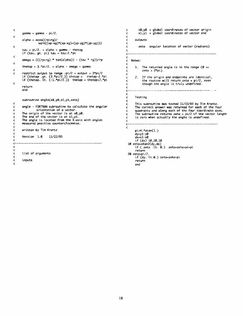
subroutine angle(xQ,yB,xl,yl,zeta)
angle - FORTRAN subroutine to calculate the angutar
orientation of o vector.
The origin of the vector is at x@,y@.
The end of the vector is at xl,yl.
The ongte is located from the X-axis with angles
measured positive counterclockwise.
written by Tim Krontz
Version 1.0 11/22/93
C ....................................................
C
C
c list of arguments
c
c inputs
C
c x0,y@ = global coordinates of vector origin
c xl,yl =gIobal coordinates of vector end
c
c outputsc
c zeta anguIor Iocation of vector (radians)
C
C .....................................................
C
c Notes :
C
C i.
C
c
c 2.
C
c
C
The returned angle is in the range (0 <=
zeta < 2*pi).
If the origin and endpoints are identical,
the routine will return zeta = pi/2, even
though the angle is truty undefined.
C .....................................................
C
c TestingC
c This subroutine was tested 11/23/93 by Tim Krontz.
c The correct answer was returned for each of the four
c quadrants and along each of the four coordinate axes.
c The subroutine returns zeta = pi/2 if the vector length
c is zero when actually the angle is undefined.
C
C ......................................................
C
pi--4.*atan(1.)
dy=yl-yOdx=xl-xO
if (dx) 10,20,10
10 zeto=aton2(dy,dx)
if ( zeta .It. 0.) zeta=zeta+pi+pireturn
20 zeto=pi/2.
if (dy. tt.O.) zeta=zeta+pi
return
end
]8
Form ApprovedREPORT DOCUMENTATION PAGE OMBNo. 0704-0188
Public reporting burden for this collection of information is estimated to average 1 hour per response, including the time for reviewing instructions, seamhing existing data sources,gathanng and maintaining the data needed, and completing and reviewing the collection of information. Send comments regarding this burden estimate or any other aspect of thiscollection of information, including suggestions for reducing this burden, to Washington Headquarters Services, Directorate for Information Operations and Reports, 1215 JeffersonDavis Highway, Suite 1204, Arlington, VA 22202-4302, and to the Office of Management and Budget, Paperwork Reduction Project (0704-0188), Washington, DC 20503.
1. AGENCY USE ONLY (Leave blank) 2. REPORT DATE 3. REPORT TYPE AND DATES COVERED
September 1996 Technical Memorandum
4. TITLE AND SUBTITLE 5. FUNDING NUMBERS
A Method to Analyze and Optimize the Load Sharing of Split Path Transmissions
6. AUTHOR(S)
Timothy L. Krantz
7. PERFORMING ORGANIZATION NAME(S) AND ADDRESS(ES)NASA Lewis Research Center
Cleveland, Ohio 44135-3191
and
Vehicle Propulsion Directorate
U.S. Army Research Laboratory
Cleveland, Ohio 44135-3191
9. SPONSORINGJMONITORING AGENCY NAME(S) AND ADDRESS(ES)
National Aeronautics and Space Administration
Washington, D.C. 20546--0001and
U.S. Army Research Laboratory
Adelphi, Maryland 20783-1145
WU-505-62-36
1L162211A47A
8. PERFORMING ORGANIZATION
REPORT NUMBER
E-10186
10. SPONSORING/MONITORING
AGENCY REPORT NUMBER
NASA TM-107201
ARL-TR-1066
11. SUPPLEMENTARY NOTES
Prepared for the Seventh International Power Transmission and Gearing Conference sponsored by the American Associa-
tion of Mechanical Engineers, San Diego, California, October 6-9, 1996. Responsible person, Timothy L. Krantz,
organization code 2730, (216) 433-3580.
12a. DISTRIBUTION/AVAILABILITY STATEMENT
Unclassified - Unlimited
Subject Category 37
This publication is available from the NASA Center for AeroSpace Information, (301 ) 621-0390.
12b. DISTRIBUTION CODE
13. ABSTRACT (Maximum 200 words)
Split-path transmissions are promising alternatives to the common planetary transmissions for rotorcraft. Heretofore,
split-path designsproposed for or used in rotorcraft have featured load-sharing devices that add undesirable weight and
complexity to the designs. A method was developed to analyze and optimize the load sharing in split-path transmissions
without load-sharing devices. The method uses the clocking angle as a design parameter to optimize for equal load
sharing. In addition, the clocking angle tolerance necessary to maintain acceptable load sharing can be calculated. The
method evaluates the effects of gearshaft twisting and bending, tooth bending, Hertzian deformations within bearings,
and movement of bearing supports on load sharing. It was used to study the NASA split-path test gearbox and the U.S.
Army's Comanche helicopter main rotor gearbox. Acceptable load sharing was found to be achievable and maintainable
by using proven manufacturing processes. The analytical results compare favorably to available
experimental data.
14. SUBJECT TERMS
Gears; Transmissions; Helicopters
17. SECURITY CLASSIFICATION
OF REPORT
Unclassified
18. SECURITY CLASSIFICATION
OF THIS PAGE
Unclassified
19. SECURITY CLASSIFICATION
OF ABSTRACT
Unclassified
15. NUMBER OF PAGES
21
16. PRICE CODE
A03
20. LIMITATION OF ABSTRACT
NSN 7540-01-280-5500 Standard Form 298 (Rev. 2-89)
Prescribed by ANSI Std. Z39-1B298-102