Page 1
A Methodology to Investigate the Dynamic Characteristics of ESP Hydraulic Units - Part II: Hardware-In-the-Loop Tests
Aldo Sorniotti
Politecnico di Torino, Department of Mechanics
Corso Duca degli Abruzzi 24
10129 Torino
ITALY
[email protected]
Prof. Nikos E. Mastorakis
WSEAS, Agiou Ioannou Theologou 17-23,
15773, Zografou, Athens,
GREECE
[email protected]
http://www.wseas.org/mastorakis
Abstract - The paper deals with the Hardware-In-the-Loop based methodology which was adopted to evaluate the dynamic
characteristics of Electronic Stability Program (ESP) and Electro-Hydraulic Brake (EHB) system components. Firstly, it permits the
identification of the time delays due to the hardware of the actuation system. Secondly, the link between the hardware of the hydraulic
unit and a vehicle model running in real time permits the objective evaluation of the performance induced by the single components of
different hydraulic units in terms of vehicle dynamics. The second part of this paper suggests the Hardware-In-the-Loop (HIL) tests
which can be adopted to evaluate the influence exerted by the hydraulic hardware of the brake system on vehicle dynamics and
handling.
Keywords – Vehicle model, Electronic Stability Program, Delays
1. The Connection between the Hardware
and the Vehicle Model This paper describes the procedure for the evaluation of the
performance of ESP hydraulic units and their effect on vehicle
dynamics. The instrument is Politecnico di Torino HIL braking
systems test bench [1], as stated in the first part. It is
characterized by the hardware of a whole brake system. The
bench hydraulic unit permits the actuation of booster input rod,
which can be controlled both in force and displacement.
Pressure sensors are located in correspondence of the main
components of the brake system. Pressure sensors at the
wheels calipers send their signals to the vehicle model [2]
which runs in real time on a dSpace card. On the basis of
pressure sensors, brake torques at the wheels are computed and
given as an input to the vehicle model. The vehicle model is
properly implemented for this HIL application. For example, it
considers in detail the equivalent inertia of the engine
computed at the wheels, to simulate the correct wheel
dynamics during emergency brake maneuvers carried out at
different gear ratios. Tire relaxation length variation as a
function of slips and vertical load is taken into account.
Interaction between lateral and longitudinal forces between
tires and ground is considered, through the adoption of
Pacejka Magic Formula. During braking with Anti-lock Brake
System (ABS), temporary locking phenomena of the wheels
can happen. To obtain realistic results, it is necessary to
consider the transitions from kinetic to static friction and vice
versa between brake pads and discs. When wheels are not
locked, brake torque TBRAKE for each wheel is computed as:
rBFAppT CWClBRAKE ⋅⋅⋅⋅−= η)( 0 (1)
where pl is line pressure (measured at the calipers), p0 is
pushout pressure, AWC is the equivalent area of the wheel
cylinder, ηc is the efficiency of the wheel cylinder, r is the
equivalent radius of the disc or drum, BF is the brake factor
(the constant factor between brake actuation force and brake
drag force). BF corresponds to two times the friction
coefficient between pads and disc in the case of a disc brake,
whereas it depends both on friction and the geometry for a
drum brake. When wheels are not locked, BF can be
considered either a constant or a function of pressure, sliding
speed and temperature, according to the target of the test.
When wheels are locked, it is necessary to compute BF so that
the wheel remains locked without turning in the opposite
direction (in comparison with the direction of the motion
before wheel locking). This task can be achieved by computing
the brake factor during static friction with the following
formula:
rApp
RFTBF
CWCl
lxm
static⋅⋅⋅−
⋅−=
η)( 0
(2)
where Tm is the torque from the differential, Rl is the loaded
radius of the wheel, Fx is the longitudinal force between the
tire and the ground. During static friction, the following
condition has to be satisfied:
max,staticstatic BFBF ≤
(3)
where BFstatic,max is the maximum value that the brake factor
can assume in static conditions of friction between the pads
and the disc. If (3) is not satisfied, the brake factor is equal to
the value corresponding to kinetic friction. The computed
value of the brake factor for static and kinetic friction is
inserted in the equation of the rotational equilibrium of the
wheel:
ITRFTT reslxBRAKEm ⋅=−−− ω&
(4)
where Tres is tires drag torque, •
ω is wheel rotational
acceleration, I is the inertial momentum of the wheel. The
vehicle model behaves as a consequence of the experimental
Proceedings of the 4th WSEAS International Conference on Fluid Mechanics and Aerodynamics, Elounda, Greece, August 21-23, 2006 (pp275-281)
Page 2
pressures measured at the calipers. This activity is devoted to
the evaluation of the main parameters of the hardware of the
hydraulic unit which can have an influence on ESP
performance from the point of view of vehicle dynamics. As a
consequence, the work here presented consists in activating the
motor pump and the electro-valves of different hydraulic units,
by-passing their control algorithms. The adopted electronic
hardware for this target is described in [1]. Together with the
vehicle model, devoted control algorithms (developed by the
author) run in real time and are linked to the tested ESP
hydraulic unit. The typical time histories for testing the
components of the ESP are automatically implemented by
these control algorithms. The behavior of each component of
ESP hydraulics can be objectively characterized, first of all
independently of the vehicle model, as shown in the first paper
about this activity. Then more sophisticated control algorithms
are adopted to simulate the behavior of commercial ESP
software. In this configuration, the hardware of the brake
system is linked to the vehicle model and can be used for the
HIL evaluation of the influence of ESP hydraulics on vehicle
dynamics. The results which will be presented in the following
pages about EHB applied to ABS (Anti-lock Brake System),
Traction Control and body yaw rate control are simulation
results on the basis of EHB experimental actuation delays
measured on an EHB bench [3]. The results about ESP
hydraulic units are experimental results of Politecnico di
Torino braking systems HIL test bench.
2. The Influence of the Hydraulic Unit
Performance on Vehicle Dynamics In this paragraph an ESP control algorithm is implemented on
the brake system HIL test bench. The vehicle model is linked
to the hardware of the brake system, as described in the first
paragraph. The performance variation due to the adoption of
different hydraulic units will be considered. In particular, the
performance improvement connected with the adoption of an
EHB system over an ESP will be described. The implemented
ESP algorithm is based on feedback yaw rate control [1].
THE EFFECT OF ESP HYDRAULIC UNIT ON ABS
PERFORMANCE
The actuation algorithm is based on the succession of pressure
increase, maintenance and decay phases for ABS,
characterized by a 4-channel control algorithm developed by
the Vehicle Dynamics Research Team of Politecnico di
Torino. Figures 1 and 2 are related to the implementation of
the ABS algorithm by adopting an old generation ABS
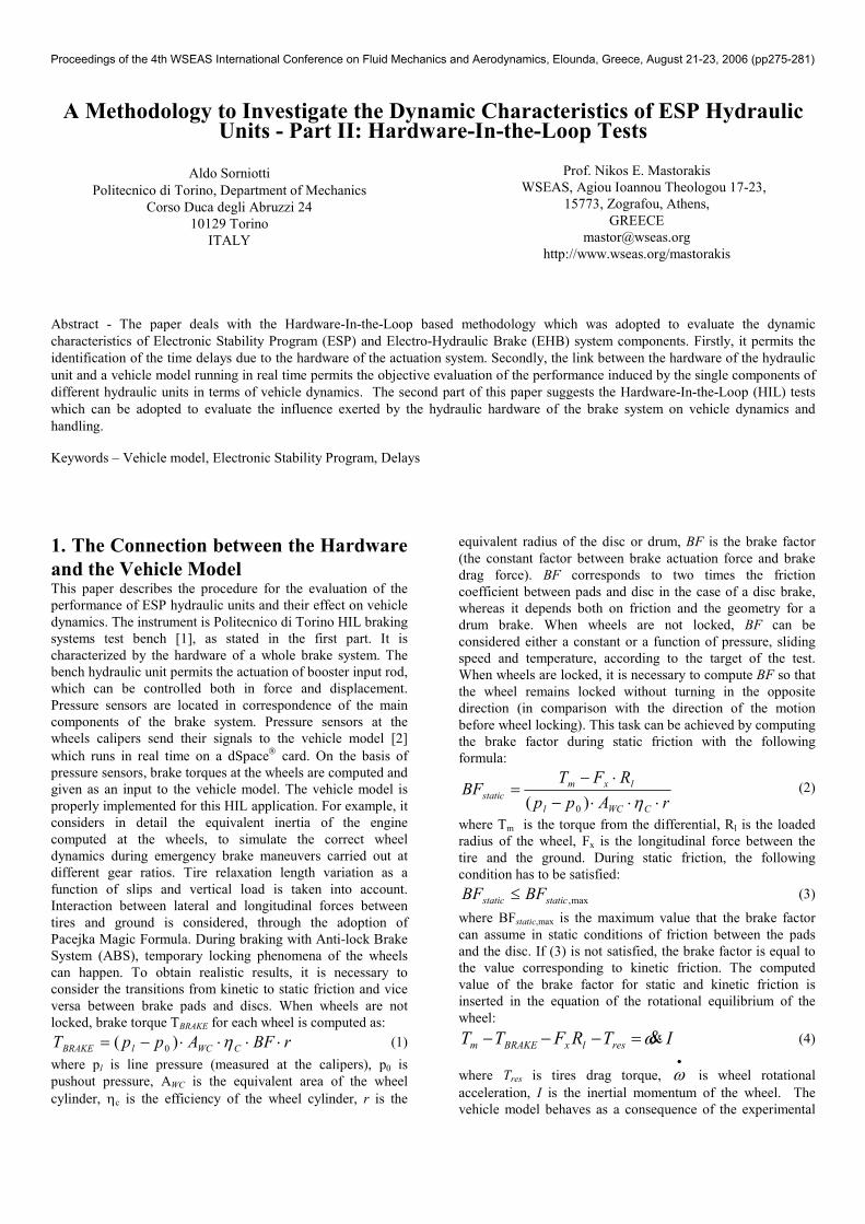
hydraulic unit. Figure 1 plots the time history of Left Rear
(LR) and Right Front (RF) caliper pressures during an
emergency brake. The two calipers belong to the same
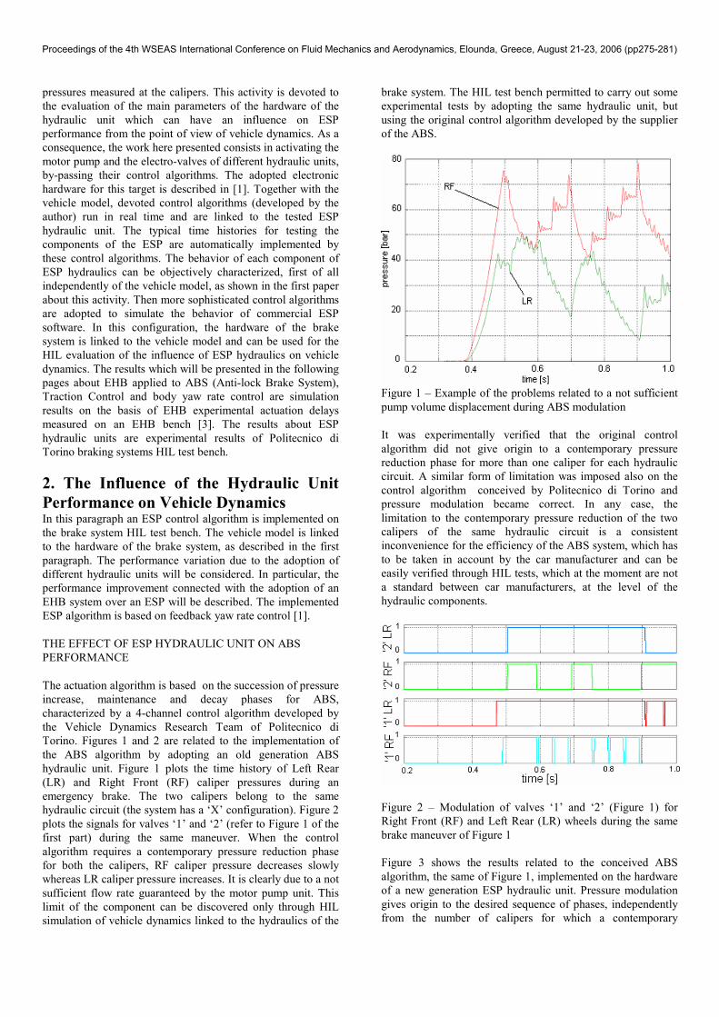
hydraulic circuit (the system has a ‘X’ configuration). Figure 2
plots the signals for valves ‘1’ and ‘2’ (refer to Figure 1 of the
first part) during the same maneuver. When the control
algorithm requires a contemporary pressure reduction phase
for both the calipers, RF caliper pressure decreases slowly
whereas LR caliper pressure increases. It is clearly due to a not
sufficient flow rate guaranteed by the motor pump unit. This
limit of the component can be discovered only through HIL
simulation of vehicle dynamics linked to the hydraulics of the
brake system. The HIL test bench permitted to carry out some
experimental tests by adopting the same hydraulic unit, but
using the original control algorithm developed by the supplier
of the ABS.
Figure 1 – Example of the problems related to a not sufficient
pump volume displacement during ABS modulation
It was experimentally verified that the original control
algorithm did not give origin to a contemporary pressure
reduction phase for more than one caliper for each hydraulic
circuit. A similar form of limitation was imposed also on the
control algorithm conceived by Politecnico di Torino and
pressure modulation became correct. In any case, the
limitation to the contemporary pressure reduction of the two
calipers of the same hydraulic circuit is a consistent
inconvenience for the efficiency of the ABS system, which has
to be taken in account by the car manufacturer and can be
easily verified through HIL tests, which at the moment are not
a standard between car manufacturers, at the level of the
hydraulic components.
Figure 2 – Modulation of valves ‘1’ and ‘2’ (Figure 1) for
Right Front (RF) and Left Rear (LR) wheels during the same
brake maneuver of Figure 1
Figure 3 shows the results related to the conceived ABS
algorithm, the same of Figure 1, implemented on the hardware
of a new generation ESP hydraulic unit. Pressure modulation
gives origin to the desired sequence of phases, independently
from the number of calipers for which a contemporary
Proceedings of the 4th WSEAS International Conference on Fluid Mechanics and Aerodynamics, Elounda, Greece, August 21-23, 2006 (pp275-281)
Page 3
pressure reduction phase is requested. The fundamental
importance of the properties of the motor pumps of
conventional ESP hydraulic units to have a good ABS control
is demonstrated.
Figure 3 – Example of the implementation of the conceived
ABS algorithm on a new generation commercial ESP unit (its
pump has a larger flow rate)
Figure 4 – Example of improvement of the ABS performance
related to the adoption of an EHB hydraulic unit [3]
Figure 4 shows the benefits related to the adoption of an EHB
hydraulic unit [3]. EHB hydraulic units can be useful to
improve ABS performance not only from the hydraulic point
of view, but from the point of view of the control algorithm. In
fact, pressure sensors (necessary for pressure modulation) at
the output ports of EHB hydraulic units can be used for a
better estimation of friction coefficient between tires and
ground. A locking tendency at a low pressure corresponds to
low friction, the opposite for a locking tendency at a high
pressure level. Secondly, ABS reference pressure level can be
imposed as a continuously varying function of wheels
peripheral acceleration and estimated slips, and not only as a
sequence of discrete states of pressure reduction, maintenance
and increase. Figure 4 was obtained with the same basic ABS
control algorithm of Figures 1 and 3, with the mentioned
improvements due to EHB implementation. Pressure
oscillations entity during the maneuver is consistently reduced,
from an average level of more than 20 bar for conventional
ESP units, to a maximum level of 10 bar for EHB.
THE EFFECT OF ESP HYDRAULIC UNIT ON THE
PERFORMANCE OF TRACTION CONTROL AND BODY
YAW RATE CONTROL
This paragraph deals with the effect of the performance of ESP
hydraulics on Traction Control (TC) and body yaw rate
control.
The implemented actuation algorithm
The case which is focused here is that one of ESP
interventions when the driver is not pushing the brake pedal.
This case implies the same kind of actuation both for body
yaw rate and traction control. In literature, several solutions
for ESP actuation are presented, for example based on a
feedback control of tires longitudinal slips [4] to generate the
desired yaw torque. In any case, an estimation of the forces
between the tires and the ground is performed by the ESP
control algorithm, on the basis of the estimated pressure
generated at the calipers by the hydraulic unit. The actuation
algorithm implemented during this activity is capable of
generating the desired pressure at the caliper according to an
open-loop control algorithm, without using caliper pressure
signals. Caliper pressures are not measured by conventional
ESP hydraulic units for reasons of cost. This actuation
algorithm was adopted for the comparison between the
performance of different commercial hydraulic units. A
simplified version of this control algorithm was presented in
[1]. During the pressure increase phase, a continuous
estimation of the actual pressure level p is performed, on the
basis of a table, having as inputs two variables, pauxiliary and
tactivation.
),( activationauxiliary tpfp =
(5)
tactivation is computed by a counter which starts at the instant in
which the motor pump is activated and stops when the pump is
switched off. During pressure maintenance and pressure
increase phases, pauxiliary is equal to the value of the estimated
pressure p at the end of the last activation of the motor pump:
activationendauxiliary pp _=
(6)
During pressure reduction phases, it is:
referenceauxiliary pp =
(7)
In such a way, a first approximation estimation of caliper
pressure during ESP actuation is performed. ESP intervenes on
the two calipers of the same side for yaw rate control and on
one or two calipers of the same axle for TC. The considered
vehicle is equipped with a ‘X’ configuration of the brake
system. As a consequence, a contemporary actuation of more
than one caliper of the same hydraulic circuit cannot happen.
The minimum duration of motor pump intervention is imposed
on the basis of a table (reported in Figure 5) defined according
to experimental tests like those summarized in the first paper
about this activity.
)(1min auxiliarypft =
(8)
During pressure decay, ‘2’ valves (look at Figure 1 of the first
part) are subjected to PWM modulation, as described in [1],
Proceedings of the 4th WSEAS International Conference on Fluid Mechanics and Aerodynamics, Elounda, Greece, August 21-23, 2006 (pp275-281)
Page 4
on the basis of actual pressure level and the desired pressure
gradient.
Figure 5 – Minimum duration of pump intervention as a
function of pauxiliary
Figure 6 – Example of test to verify the performance of the
actuation algorithm
Figures 6 and 7 show comparisons between the desired and the
obtained pressure level. It is evident the consistent
approximation in pressure modulation, especially during the
pressure reduction phase, due to the slow dynamics of the ‘2’
valves of the considered hydraulic unit. For an EHB unit the
reference caliper pressures of Figures 6 and 7 would
correspond to the equivalent of a base brake maneuver
(decided by the driver) and would be performed with a nearly
null offset between reference and measured pressures (thanks
to the efficiency of EHB valves and to the pressure sensors
adopted inside EHB hydraulics to measure pressure levels at
the output ports of the hydraulic unit).
Figure 7 – Example of test to verify the performance of the
actuation algorithm: comparison between reference and
measured pressures
The effect of ESP hydraulics for TC performance
Figures 8 and 9 are about a start-up maneuver in split-µ
conditions. They compare the experimental behavior
(measured at the test bench) of a vehicle equipped with a
commercial ESP unit, actuated according to the algorithm
described in the former paragraph, and a vehicle equipped with
a simulated EHB hydraulic unit. At about 8 s, at the end of the
brakes intervention, the vehicle with the commercial ESP has
obtained only the 70% of the useful effect in terms of
longitudinal speed, in comparison to an EHB unit.
Figure 8 – Time history of low adherence caliper pressure
during a start-up maneuver in split-µ conditions
The efficiency of the hydraulic unit with the control algorithm
can be computed by the following index:
brakeendpassive
brakeendpassivebrakeendactive
V
VVI
_,
_,_,
1
−= (9)
Proceedings of the 4th WSEAS International Conference on Fluid Mechanics and Aerodynamics, Elounda, Greece, August 21-23, 2006 (pp275-281)
Page 5
where Vactive,end_brake is the longitudinal speed of the vehicle
with TC at the end of the brake intervention carried out by TC
and Vpassive,end_brake is the longitudinal speed of the passive
vehicle in correspondence of the end of brakes intervention for
the active vehicle (this kind of comparison between a passive
and an active vehicle is possible only thanks to HIL
simulation, it would be too difficult in the form of road tests).
The higher is the value of the index, the more efficient is the
evaluated TC system.
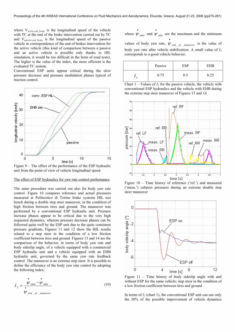
Conventional ESP units appear critical during the slow
pressure decrease and pressure modulation phases typical of
traction control.
Figure 9 – The effect of the performance of the ESP hydraulic
unit from the point of view of vehicle longitudinal speed
The effect of ESP hydraulics for yaw rate control performance
The same procedure was carried out also for body yaw rate
control. Figure 10 compares reference and actual pressures
measured at Politecnico di Torino brake systems HIL test
bench during a double step steer maneuver, in the condition of
high friction between tires and ground. The maneuver was
performed by a conventional ESP hydraulic unit. Pressure
increase phases appear to be critical due to the very high
requested dynamics, whereas pressure decrease phases can be
followed quite well by the ESP unit due to the quite consistent
pressure gradients. Figures 11 and 12 show the HIL results
related to a step steer in the condition of a low friction
coefficient between tires and ground. Figures 13 and 14 are the
comparison of the behavior, in terms of body yaw rate and
body sideslip angle, of a vehicle equipped with a commercial
ESP hydraulic unit and a vehicle equipped with an EHB
hydraulic unit, governed by the same yaw rate feedback
control. The maneuver is an extreme step steer. It is possible to
define the efficiency of the body yaw rate control by adopting
the following index:
maneuverofend
I
__
minmax
2 •
••
−=
ψ
ψψ (10)
where max
•
ψ and min
•
ψ are the maximum and the minimum
values of body yaw rate, maneuverofend __
•
ψ is the value of
body yaw rate after vehicle stabilization. A small value of I2
corresponds to a good vehicle behavior.
Passive ESP EHB
2I 0.75 0.5 0.25
Chart 1 – Values of I2 for the passive vehicle, the vehicle with
conventional ESP hydraulics and the vehicle with EHB during
the extreme step steer maneuver of Figures 13 and 14
Figure 10 – Time history of reference (‘ref.’) and measured
(‘meas.’) calipers pressures during an extreme double step
steer maneuver
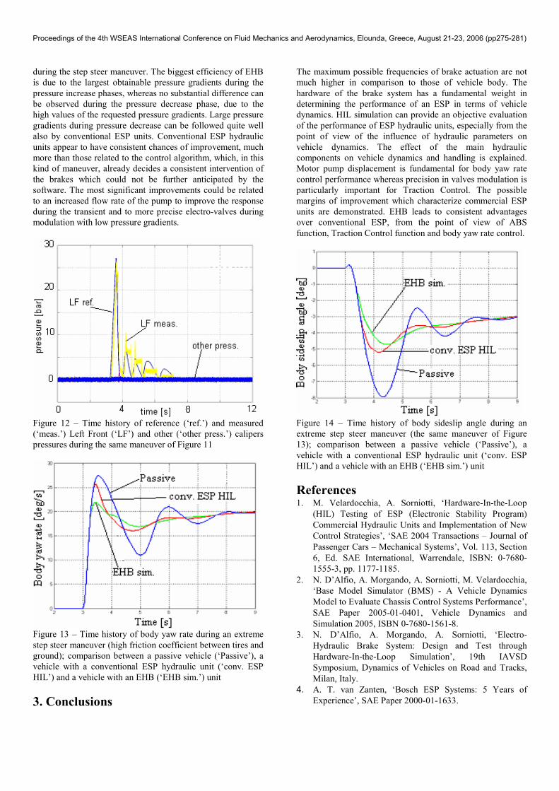
Figure 11 – Time history of body sideslip angle with and
without ESP for the same vehicle; step steer in the condition of
a low friction coefficient between tires and ground
In terms of I2 (chart 1), the conventional ESP unit can use only
the 50% of the possible improvement of vehicle dynamics
Proceedings of the 4th WSEAS International Conference on Fluid Mechanics and Aerodynamics, Elounda, Greece, August 21-23, 2006 (pp275-281)
Page 6
during the step steer maneuver. The biggest efficiency of EHB
is due to the largest obtainable pressure gradients during the
pressure increase phases, whereas no substantial difference can
be observed during the pressure decrease phase, due to the
high values of the requested pressure gradients. Large pressure
gradients during pressure decrease can be followed quite well
also by conventional ESP units. Conventional ESP hydraulic
units appear to have consistent chances of improvement, much
more than those related to the control algorithm, which, in this
kind of maneuver, already decides a consistent intervention of
the brakes which could not be further anticipated by the
software. The most significant improvements could be related
to an increased flow rate of the pump to improve the response
during the transient and to more precise electro-valves during
modulation with low pressure gradients.
Figure 12 – Time history of reference (‘ref.’) and measured
(‘meas.’) Left Front (‘LF’) and other (‘other press.’) calipers
pressures during the same maneuver of Figure 11
Figure 13 – Time history of body yaw rate during an extreme
step steer maneuver (high friction coefficient between tires and
ground); comparison between a passive vehicle (‘Passive’), a
vehicle with a conventional ESP hydraulic unit (‘conv. ESP
HIL’) and a vehicle with an EHB (‘EHB sim.’) unit
3. Conclusions
The maximum possible frequencies of brake actuation are not
much higher in comparison to those of vehicle body. The
hardware of the brake system has a fundamental weight in
determining the performance of an ESP in terms of vehicle
dynamics. HIL simulation can provide an objective evaluation
of the performance of ESP hydraulic units, especially from the
point of view of the influence of hydraulic parameters on
vehicle dynamics. The effect of the main hydraulic
components on vehicle dynamics and handling is explained.
Motor pump displacement is fundamental for body yaw rate
control performance whereas precision in valves modulation is
particularly important for Traction Control. The possible
margins of improvement which characterize commercial ESP
units are demonstrated. EHB leads to consistent advantages
over conventional ESP, from the point of view of ABS
function, Traction Control function and body yaw rate control.
Figure 14 – Time history of body sideslip angle during an
extreme step steer maneuver (the same maneuver of Figure
13); comparison between a passive vehicle (‘Passive’), a
vehicle with a conventional ESP hydraulic unit (‘conv. ESP
HIL’) and a vehicle with an EHB (‘EHB sim.’) unit
References 1. M. Velardocchia, A. Sorniotti, ‘Hardware-In-the-Loop
(HIL) Testing of ESP (Electronic Stability Program)
Commercial Hydraulic Units and Implementation of New
Control Strategies’, ‘SAE 2004 Transactions – Journal of
Passenger Cars – Mechanical Systems’, Vol. 113, Section
6, Ed. SAE International, Warrendale, ISBN: 0-7680-
1555-3, pp. 1177-1185.
2. N. D’Alfio, A. Morgando, A. Sorniotti, M. Velardocchia,
‘Base Model Simulator (BMS) - A Vehicle Dynamics
Model to Evaluate Chassis Control Systems Performance’,
SAE Paper 2005-01-0401, Vehicle Dynamics and
Simulation 2005, ISBN 0-7680-1561-8.
3. N. D’Alfio, A. Morgando, A. Sorniotti, ‘Electro-
Hydraulic Brake System: Design and Test through
Hardware-In-the-Loop Simulation’, 19th IAVSD
Symposium, Dynamics of Vehicles on Road and Tracks,
Milan, Italy.
4. A. T. van Zanten, ‘Bosch ESP Systems: 5 Years of
Experience’, SAE Paper 2000-01-1633.
Proceedings of the 4th WSEAS International Conference on Fluid Mechanics and Aerodynamics, Elounda, Greece, August 21-23, 2006 (pp275-281)
Page 7
Contact
Aldo Sorniotti, Politecnico di Torino, Department of
Mechanics, Corso Duca degli Abruzzi 24, 10129 Torino,
ITALY, email: [email protected]
Proceedings of the 4th WSEAS International Conference on Fluid Mechanics and Aerodynamics, Elounda, Greece, August 21-23, 2006 (pp275-281)