23
A microprocessor is a multipurpose, programmable logic device that reads binaryprogrammable logic device that reads binary instructions from a storage device called memory accepts binary data as input andmemory accepts binary data as input and processes data according to those instructions and provides result as outputand provides result as output.
It is used in many microprocessor based electronic devices
i. For measurements, display and control of current, voltage, temperature, pressure, etc.
ii For traffic control and industrial tool controlii. For traffic control and industrial tool control.iii. For speed control of machines.


The features of INTEL 8085 are :1 It is an 8 bit processor1. It is an 8 bit processor.2. It is a single chip N-MOS device with 40 pins.3. It has multiplexed address and data bus.(AD0-p (AD7).4. It works on 5 Volt dc power supply.5. The maximum clock frequency is 3 MHz while minimum frequency is 500kHz.6 It provides 74 instructions with 5 different6. It provides 74 instructions with 5 different addressing modes.
8085 require +5V power supply and 3MHz. clock frequency.
FUNCTIONS OF AN ACCUMULATOR:The accumulator is a register associated with the A i d i /O iALU operations and sometimes I/O operations.It is an integral part of ALU.I h ld f d b d b ALU I lIt holds one of data to be processed by ALU. It also temporarily stores the result of the operation performed by the ALUperformed by the ALU.


B-C register pairD-E register pairH-L register pair
1. Temporary data register2 Temporary registers W and Z2. Temporary registers W and Z3. 8-bit accumulator4. Flag register4. Flag register5. Six general purpose registers (B, C, D, E, H and L)6. 16-bit program counter :6. 16 bit program counter :7. 16-bit stack pointer -8. Instruction register.g
(1) Temporary Data Register : This register is also called as operand register. It provides operands to the ALU. It is a 8-bit register and not available to user.
(2) Temporary Registers (W and Z) : These registers(2) Temporary Registers (W and Z) : These registers are used by control section to hold the data during an arithmetic or logical operation. It is hold 8 bit data. These register are not available to user They areThese register are not available to user. They are internally used by the microprocessor.
e.g.:(a) XCHG (exchange)(b) XTHL (exchange top of stack with registers H and(b) XTHL (exchange top of stack with registers H and
L).
(3) 8-bit accumulator : This register is used to store(3) 8 bit accumulator : This register is used to store
the first input as well as result of any calculation is
also stored in accumulator. The accumulator is
identified as register A. It is an 8-bit general purposeidentified as register A. It is an 8 bit general purpose
register.

(a) Sign Flag (S)(b) Zero Flag (Z)(c) Auxiliary Carry Flag (AC)(d) P it Fl (P)(d) Parity Flag (P)(e) Carry Flag (CV)
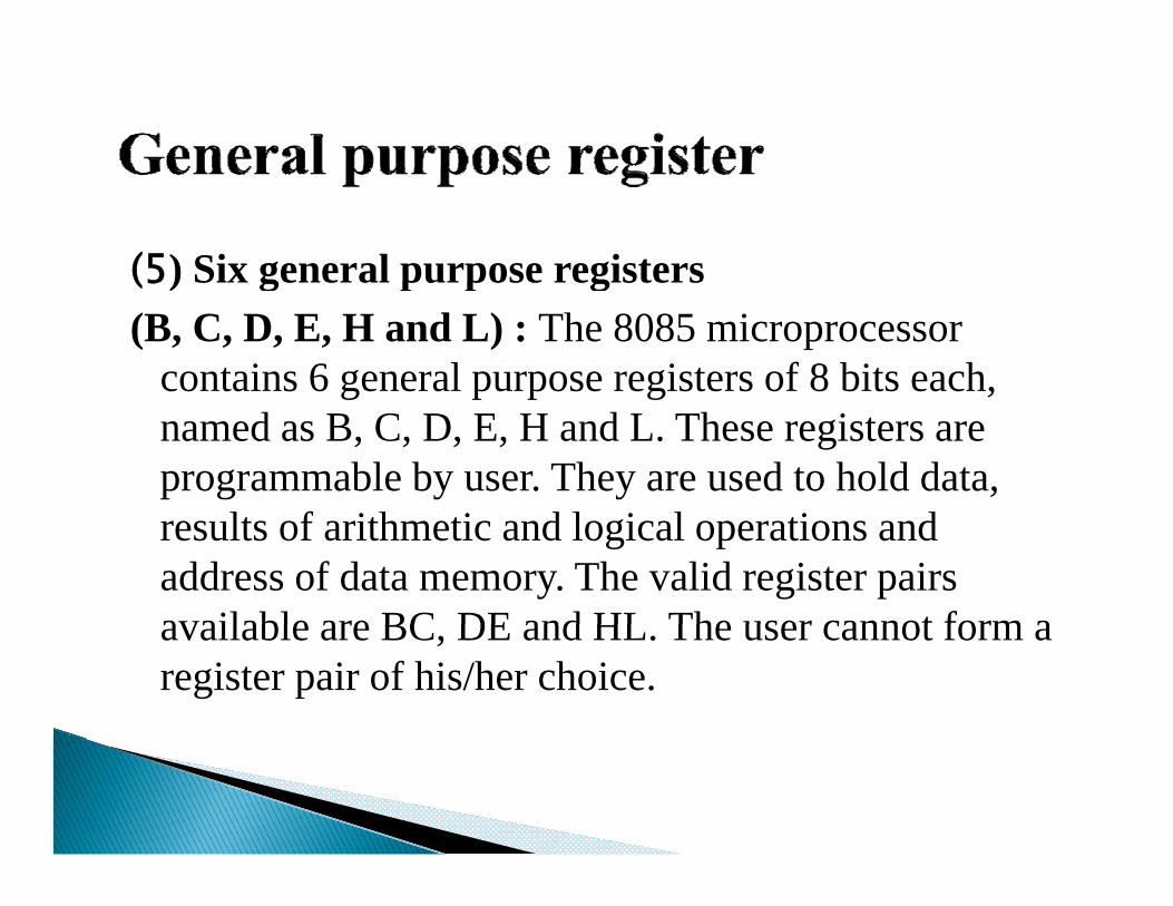
(5) Six general purpose registers(5) Six general purpose registers (B, C, D, E, H and L) : The 8085 microprocessor
contains 6 general purpose registers of 8 bits each, g p p g ,named as B, C, D, E, H and L. These registers are programmable by user. They are used to hold data, results of arithmetic and logical operations and address of data memory. The valid register pairs available are BC DE and HL The user cannot form aavailable are BC, DE and HL. The user cannot form a register pair of his/her choice.

(6) 16-bit program counter (PC) : The programcounter is used to hold the address of programcounter is used to hold the address of programmemory. It always points to the next instruction to befetched i.e. it holds the memory address of the nextyinstruction to be executed.
(7) 16 bit St k P i t (SP) St k i d(7) 16-bit Stack Pointer (SP): Stack is a reservedportion of memory where information can be storedto taken back under software control. This memoryo a e bac u de so wa e co o . s e o yarea is referred to as stack area. The stack pointer isauto decremented by 2 after PUSH operation and
t i t d b 2 ft POP tiauto incremented by 2 after POP operation.
(8) Instruction Register: An instruction fetched from memory is temporarily stored in Instruction Register before decoding. So after fetching instruction from
i i i h i imemory, microprocessor stores it in the instruction register and after this it is decoded.
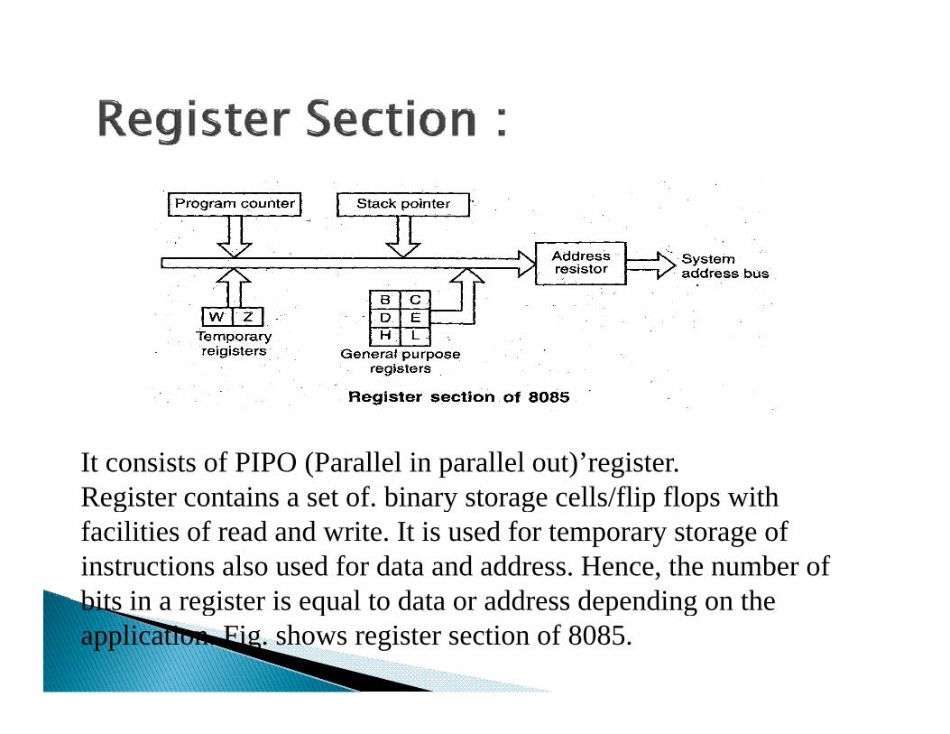
It consists of PIPO (Parallel in parallel out)’register.Register contains a set of. binary storage cells/flip flops withRegister contains a set of. binary storage cells/flip flops with facilities of read and write. It is used for temporary storage of instructions also used for data and address. Hence, the number of bits in a register is equal to data or address depending on thebits in a register is equal to data or address depending on the application. Fig. shows register section of 8085.

1.The register is not accessible to user.
2. Instruction register holds the opcode of instruction that is decoded and executed.
3. This opcode is sent for instruction decoder to select one of 256 alternatives.

1. Used for holding the address of program g p gmemory.
2 In reset condition the program counter is set to2. In reset condition, the program counter is set to 000H, means that the address of first instruction to be fetched and executedto be fetched and executed.
3. The size of program counter depends upon the number of address bitsnumber of address bits.
4. In case of JUMP and call instructions, the addressfollowed by JUMP and call instructions is placed inprogram counter. If the condition is satisfied then8085 f h h i i f h8085 fetches the next instruction from the newaddress specified by JUMP or call instructions.
5. During instruction fetch operation, the contents ofprogram counter on the address bus and it fetchesprogram counter on the address bus and it fetchesfirst byte of instruction from memory location.
1. It is portion of memory where information can be stored or taken back. This memory area is known as
kstack area.
2 It is 16 bit register used for defining the stack2. It is 16-bit register used for defining the stack starting address.
3. Used to keep track of data store don stack.
4. It is loaded with an initial value by means of transfer type instruction.
This section processes all data i.e. it perform ith ti d l i tiarithmetic and logic operations.
1. It performs addition, subtraction and logical, p , g ,operations like AND, OR, EX-OR.
2. ALU is always controlled by timing and control circuitscircuits.
3. It looks after the branching decisions.4. It provides status of result to the flag register.
There are lot of research scope in field ofmicroprocessor, today word is electronic world andcomputer and electronic equipment are using in everyfi ld I h li d f f h i ifield. Improve the quality and feature of the existingmicroprocessor new research are going on. so thereare lot of research scope in this fieldare lot of research scope in this field.


