Progress In Electromagnetics Research B, Vol. 36, 357–371, 2012 A MIMO ANTENNA DESIGN CHALLENGES FOR UWB APPLICATION M. Jusoh 1 , M. F. Jamlos 1 , M. R. Kamarudin 2, * , and F. Malek 3 1 School of Computer and Communication Engineering, Universiti Malaysia Perlis (UniMAP), Kangar, Perlis 01000, Malaysia 2 Wireless Communication Centre (WCC), Faculty of Electrical En- gineering, Universiti Teknologi Malaysia, UTM Skudai, Johor 81310, Malaysia 3 School of Electrical System Engineering, Universiti Malaysia Perlis (UniMAP), Kuala Perlis, Perlis 02000, Malaysia Abstract—This paper proposes a compact printed ultra-wideband (UWB) multiple-input-multiple-output (MIMO) antenna with a dimension of 38 × 91 mm 2 . The presented UWB-MIMO antenna comprises two identical patch elements with D separation distance on the same substrate. The basic single antenna structure has a novel design comprising seven circles surrounding a center circle with partial ground plane implementation. Furthermore, the experimental antenna has peak gain of 5.3 dBi between an operating frequency of 2.8 GHz and 8.0 GHz under a minimum reflection coefficient of less than -10 dB (S 11 < -10 dB). Moreover, the antenna successfully achieved mutual coupling minimization of < -17 dB, eventually resulting in enhancement of radiation efficiency. Besides, the UWB- MIMO’s correlation coefficient was effectively reduced to less than -22dB, which reflected an improvement in the antenna’s diversity. In this paper, the proposed antenna is examined both numerically and experimentally. 1. INTRODUCTION UWB communications have received a lot of publicity in terms of future technology regarding high data rate and short-range transmission [1– 5]. Moreover, the UWB spectrum released in April 2002 by the Received 27 September 2011, Accepted 3 November 2011, Scheduled 24 November 2011 * Corresponding author: Muhammad Ramlee Bin Kamarudin ([email protected]).
Transcript
Progress In Electromagnetics Research B, Vol. 36, 357–371, 2012
A MIMO ANTENNA DESIGN CHALLENGES FOR UWBAPPLICATION
M. Jusoh 1, M. F. Jamlos 1, M. R. Kamarudin 2, *, andF. Malek 3
1School of Computer and Communication Engineering, UniversitiMalaysia Perlis (UniMAP), Kangar, Perlis 01000, Malaysia2Wireless Communication Centre (WCC), Faculty of Electrical En-gineering, Universiti Teknologi Malaysia, UTM Skudai, Johor 81310,Malaysia3School of Electrical System Engineering, Universiti Malaysia Perlis(UniMAP), Kuala Perlis, Perlis 02000, Malaysia
Abstract—This paper proposes a compact printed ultra-wideband(UWB) multiple-input-multiple-output (MIMO) antenna with adimension of 38 × 91 mm2. The presented UWB-MIMO antennacomprises two identical patch elements with D separation distanceon the same substrate. The basic single antenna structure has anovel design comprising seven circles surrounding a center circle withpartial ground plane implementation. Furthermore, the experimentalantenna has peak gain of 5.3 dBi between an operating frequency of2.8GHz and 8.0 GHz under a minimum reflection coefficient of lessthan −10 dB (S11 < −10 dB). Moreover, the antenna successfullyachieved mutual coupling minimization of < −17 dB, eventuallyresulting in enhancement of radiation efficiency. Besides, the UWB-MIMO’s correlation coefficient was effectively reduced to less than−22 dB, which reflected an improvement in the antenna’s diversity.In this paper, the proposed antenna is examined both numerically andexperimentally.
1. INTRODUCTION
UWB communications have received a lot of publicity in terms of futuretechnology regarding high data rate and short-range transmission [1–5]. Moreover, the UWB spectrum released in April 2002 by the
Received 27 September 2011, Accepted 3 November 2011, Scheduled 24 November 2011* Corresponding author: Muhammad Ramlee Bin Kamarudin ([email protected]).
358 Jusoh et al.
Federal Communication Commission (FCC) in the United States isthe required technology that fulfills the needs of healthcare provision.Permitted commercial UWB devices must be considered for a workingspectrum frequency of 3.1 GHz to 10.6 GHz with a low-power spectraldensity (PSD) not exceeding −41.3 dBm/MHz [6].
Recently, a lot of UWB antennas have been developed andestablished. A novel compact UWB antenna with high impedancebandwidth with the idea of a rectangular waveguide has beenintroduced [7]. A planar dipole antenna consisting of two semi-elliptical-ended arms connected by a shorting bridge capable ofenhancing the antenna’s impedance and gain throughout UWBoperating bandwidth is studied [8]. The interesting approach ofimplemented RF switches (PIN diode) at the feed line achieves areconfigurable planar monopole antenna [9]. A microstrip square-ringslot antenna (MSRSA) attains UWB frequency range by splitting thesquare-ring slot and optimizing the feeding network [10].
Owing to its high capacity and high-speed wireless communicationconcentration, many researchers have focused on the multiple-input-multiple-output (MIMO) antenna [11, 12]. MIMO requires severaltransmitter and receiver antennas that function simultaneously. Thedevelopment of the MIMO antenna functioning on a UWB spectrumfrequency helps to overcome multipath propagation with non-line-of-sight (NLOS), eventually resulting in the attainment of more accuratedata. Moreover, the MIMO antenna enhances channel capacity(bits/Hz) by increasing the spectrum efficiency of the channel usingEquation (1) [13, 14].
CMIMO = log[det
(IMR
+SINR
MTHHH
)](1)
MT and MR are the numbers of transmitters and receivers,respectively. While IMR is the identity matrix, MR ×MR, and H is aMT ×MT matrix. Referring to Equation (1), the capacity of MIMOcan be increased because of the increase in transmitter and receiverantenna.
However, significant issues need to be overcome to enhance theeffectiveness of MIMO. These include very low mutual coupling,low correlation, high diversity gain, and low total active reflectioncoefficient (TARC) [15–17]. As in [18], the performance of two equalantennas is discussed in terms of the antennas positioning effect of0, 90, and 180 towards mutual coupling, correlation coefficient, andradiation pattern. The two non-symmetrical antennas with minimumdistance achieve low mutual coupling preserving UWB operatingfrequency according to FCC standards.
Progress In Electromagnetics Research B, Vol. 36, 2012 359
This research proposes a compact MIMO antenna with two portsymmetrical radiating elements on the same substrate. The antenna’sradiating element consists of seven small circles surrounding the centersingle circle with a 50Ω microstrip line feed. The seven small circles(7 filters) function as a filter. In [19, 20], such filters developed fromthe external circuit eventually increase the antenna’s complexity anddimensions. To the author’s knowledge, so far, there have been no suchantennas that merge a filter into the antenna’s design. Furthermore,the 7-filters dimensions significantly influence the antenna’s impedancematching. For this design, the partial ground plane function as tuningcircuit for the antenna’s matching network.
The MIMO antenna has successfully functioned for UWBoperating frequency of 2.8 GHz to 8 GHz, with good impedancematching of −54 dB. Besides, the attainable UWB-MIMO’s gainof 6dBi is considered high compared to conventional antenna [21].Moreover, the UWB-MIMO antenna with its advantages of highbandwidth, and handy and compact size (91mm × 38mm) isaccessible for wireless communication systems [22–26]. To the authors’knowledge, the MIMO antenna’s reflection coefficient, mutual coupling,and correlation coefficient need to be analyzed collectively as theyare intimately related to each other. Hence, this research focuseson the minimization of the mutual coupling and the correlationcoefficient since a lower mutual coupling increases radiation efficiencywhile a lower correlation coefficient improves antenna diversity.Moreover, this paper presents a parameter optimization routine onthe inter element spacing (IES) varying from 0 mm to 40mm towardsreflection coefficient, mutual coupling, and correlation coefficient.The three parameters’ optimum results reflect the ultimate antennaconfiguration.
Based on the simulation result performance, the IES is set to15mm with low mutual coupling of < −17 dB and a minimumcorrelation coefficient of < −22 dB compared to that presentedin [16, 19, 27]. Then, the antenna is fabricated and measuredon impedance performance, radiation performance, and correlationcoefficient performance. The success of the experimental antennaperformances means that the antenna is suitable as a future candidatefor radar and military application.
This paper is organized as follows: Section 2 discusses the antennastructure and experimental setup. The numerical study on the effect ofIES towards the reflection coefficient, mutual coupling, and correlationcoefficient is presented in Section 3. The experimental result of IES =15mm on the S-parameter, radiation pattern, gain, and correlationcoefficient are shown as well. Section 4 presents the conclusion.
360 Jusoh et al.
2. ANTENNA STRUCTURE AND EXPERIMENTALSETUP
Figure 1 and Figure 2 illustrate the proposed UWB-MIMO antenna’sgeometry and prototype, respectively. The UWB-MIMO antennapresented consists of a combination of two identical antennas on thesame substrate. The novel antenna is developed by integrating sevensmall circles surrounding the center circle. The circles have a diameterof Rs and Rin, respectively. The impedance matching of the microstripfeed line is fixed to 50 Ω with a feed width of Wf . The structure of theantenna element has been fabricated on the Taconic TLY-5 substratewith a thickness of 1.5748 mm, dielectric permittivity, εr, of 2.2 andtangent loss, tan δ, of 0.0009.
The unique design of the proposed UWB antenna basically comesfrom a single circle structure as in [28]. Since more current distributes
Figure 1. The simulated geometry of the proposed UWB MIMOantenna.
Port 1
y
x
y
x
(a) (b)Port 2 Port 2 Port 1
D
Figure 2. The fabricated geometry of the proposed UWB MIMOantenna. (a) Front view. (b) Back view.
Progress In Electromagnetics Research B, Vol. 36, 2012 361
near the edge of the circle, this research reduces the inner circlediameter and introduces a ring with 1 mm size surrounding the circle.This eventually allows the ring to cater for the entire required currentdistribution. However, the antenna’s S11 performance still failed toachieve a UWB application. Therefore, seven small circles (7-circle)have been implemented on the ring and three bridges connected tothe 7-circle are drawn as in Figure 1 and Figure 2. As a result, theproposed antenna’s design has successfully achieved a UWB frequencyoperating.
The single antenna with the dimensions of Ls×Ws1 is developed.Then, a second antenna is drawn by replicating the first antennastructure on the same substrate. With a few of optimization routines,the final geometrical results are: Ls = 38mm, Wf = 5 mm, Rin =12mm, Rs = 6 mm, Ws1 = 38mm, and Ws2 = 38mm. Thedistance between both antennas symbolized by D will be analyzedin the sense of achieving minimum mutual coupling and low reflectioncoefficient that conserve the UWB frequency standard. All designsand simulations have been completed using CST Microwave Studio,commercial electronics simulation software.
All measurement processes have been carried out in the researchcluster of the Universiti Malaysia Perlis (UniMAP) with the help ofAgilent Technologies E83628 PNA Network Analyzer and 2D AnechoicChamber as visualized in Figure 3. The horn antenna performed asa transmitter is competent to function from 1 GHz to 18 GHz. Theantenna being tested (UWB-MIMO antenna) executes as a receiver.Both antennas are placed about 1m apart.
Figure 3. Agilent 2D PNA antenna test system.
362 Jusoh et al.
3. RESULTS AND DISCUSSION
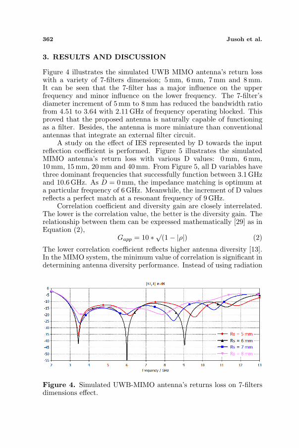
Figure 4 illustrates the simulated UWB MIMO antenna’s return losswith a variety of 7-filters dimension; 5mm, 6mm, 7 mm and 8mm.It can be seen that the 7-filter has a major influence on the upperfrequency and minor influence on the lower frequency. The 7-filter’sdiameter increment of 5 mm to 8 mm has reduced the bandwidth ratiofrom 4.51 to 3.64 with 2.11 GHz of frequency operating blocked. Thisproved that the proposed antenna is naturally capable of functioningas a filter. Besides, the antenna is more miniature than conventionalantennas that integrate an external filter circuit.
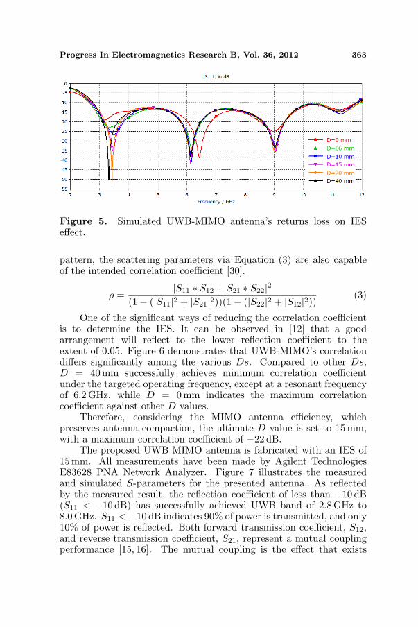
A study on the effect of IES represented by D towards the inputreflection coefficient is performed. Figure 5 illustrates the simulatedMIMO antenna’s return loss with various D values: 0 mm, 6 mm,10mm, 15 mm, 20 mm and 40 mm. From Figure 5, all D variables havethree dominant frequencies that successfully function between 3.1GHzand 10.6 GHz. As D = 0mm, the impedance matching is optimum ata particular frequency of 6 GHz. Meanwhile, the increment of D valuesreflects a perfect match at a resonant frequency of 9 GHz.
Correlation coefficient and diversity gain are closely interrelated.The lower is the correlation value, the better is the diversity gain. Therelationship between them can be expressed mathematically [29] as inEquation (2),
Gapp = 10 ∗ √(1− |ρ|) (2)
The lower correlation coefficient reflects higher antenna diversity [13].In the MIMO system, the minimum value of correlation is significant indetermining antenna diversity performance. Instead of using radiation
Figure 4. Simulated UWB-MIMO antenna’s returns loss on 7-filtersdimensions effect.
Progress In Electromagnetics Research B, Vol. 36, 2012 363
Figure 5. Simulated UWB-MIMO antenna’s returns loss on IESeffect.
pattern, the scattering parameters via Equation (3) are also capableof the intended correlation coefficient [30].
ρ =|S11 ∗ S12 + S21 ∗ S22|2
(1− (|S11|2 + |S21|2))(1− (|S22|2 + |S12|2)) (3)
One of the significant ways of reducing the correlation coefficientis to determine the IES. It can be observed in [12] that a goodarrangement will reflect to the lower reflection coefficient to theextent of 0.05. Figure 6 demonstrates that UWB-MIMO’s correlationdiffers significantly among the various Ds. Compared to other Ds,D = 40 mm successfully achieves minimum correlation coefficientunder the targeted operating frequency, except at a resonant frequencyof 6.2 GHz, while D = 0 mm indicates the maximum correlationcoefficient against other D values.
Therefore, considering the MIMO antenna efficiency, whichpreserves antenna compaction, the ultimate D value is set to 15 mm,with a maximum correlation coefficient of −22 dB.
The proposed UWB MIMO antenna is fabricated with an IES of15mm. All measurements have been made by Agilent TechnologiesE83628 PNA Network Analyzer. Figure 7 illustrates the measuredand simulated S-parameters for the presented antenna. As reflectedby the measured result, the reflection coefficient of less than −10 dB(S11 < −10 dB) has successfully achieved UWB band of 2.8GHz to8.0GHz. S11 < −10 dB indicates 90% of power is transmitted, and only10% of power is reflected. Both forward transmission coefficient, S12,and reverse transmission coefficient, S21, represent a mutual couplingperformance [15, 16]. The mutual coupling is the effect that exists
364 Jusoh et al.
Frequency, GHz
2 4 6 8 10 12
Corr
elat
ion C
oef
fici
ent,
dB
-120
-100
-80
-60
-40
-20
0
D = 0 mm
D = 6 mm
D = 10 mm
D = 15 mm
D = 20 mm
D = 40 mm
Figure 6. Simulated UWB MIMO antenna’s correlation coefficient onIES effect.
0
-20
S11
/ S
21
-40
Measured S11
-60 Measured S21
Simulated S11
Simulated S21
-80
2 4 6 8 10
Frequency, GHz
Figure 7. Measured and simulated S-parameters of the proposedUWB MIMO antenna.
due to the electromagnetic (EM) interaction between adjacent antennaelements. The decrement of mutual coupling results in an improvementin radiation efficiency and vice versa [15]. As in Figure 7, the measuredmutual coupling (S21) effectively achieves a maximum of−17 dB, whichis considered better than [15, 16, 19, 25].
To further elaborate the electromagnetic interactions of theadjacent circuit, the proposed antenna’s isolation can be observed by
Progress In Electromagnetics Research B, Vol. 36, 2012 365
the surface current distribution. Figure 8 shows two cases of currentdistributions at two frequencies of 6 GHz and 9GHz. The 1st case iswhen Port 1 is excited while Port 2 is terminated with a load impedanceof 50 Ω, and the 2nd case is vice versa. Both cases show that lesscurrent has been attracted to the adjacent element eventually reducedthe mutual coupling effect and increased the radiation efficiency. As inFigure 9, the proposed antenna has great radiation and total (antenna)efficiency throughout the desired frequency operating. Generally, totalefficiency is smaller than radiation efficiency due to the reflection lossinstead of dielectric and copper loss. The total efficiency increasesup to 50% from 2GHz to 3 GHz. A proposed UWB-MIMO antenna
(a) 6 GHz (b) 6 GHz
(c) 9 GHz (d) 9 GHz
Figure 8. Surface current distributions (contour) of antenna. (a) and(c) when Port 1 is excited. (b) and (d) when Port 2 is excited.
Frequency, GHz
2 4 6 8 10
Eff
icie
ncy
20
30
40
50
60
70
80
90
100
Total Efficiency
Radiation Efficiency
Figure 9. Simulated efficiency of the proposed antenna.
366 Jusoh et al.
has successfully achieved total efficiency of 80% to 92% as depicted inFigure 9. This contributes to the lower of mutual coupling effect.
Figure 10 indicates a measured UWB-MIMO antenna’s E-plane(yz-plane) of co-polar and cross-polar radiation patterns at thespecified frequencies of f1 = 4 GHz, f2 = 7 GHz and f3 = 10 GHz.The measured cross-polar is slightly different from the co-polar, whichshows a non-stable linear polarization. As the proposed antenna is ofidentical design, the radiation and total antenna efficiency are similarfor both ports. Therefore, the measurement is carried out with Port 1excited while Port 2 is terminated to 50Ω load impedance.
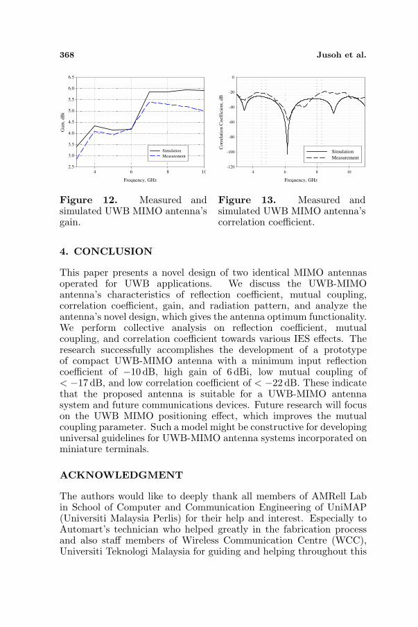
The antenna’s gain is approximately the same in both identicalantenna designs. The measurement was performed only by excited Port1, while Port 2 was terminated with 50 Ω load. Figure 12 comparesthe measured and simulated UWB MIMO antenna’s gain against the
UWB operating frequency (2GHz to 11 GHz). Both results have smalldifferences due to minor fabrication tolerance. The measured gaininstantly increases from 2.8 dBi to 5.2 dBi between 3GHz to 7GHz.At 7GHz to 9GHz, the UWB-MIMO antenna has peak and constantgain of 5.2 dBi. The gain slopes from 5.2 dBi at 9 GHz to 4.1 dBi at11GHz.
The correlation coefficient is the crucial parameter to determineMIMO antenna diversity performance and can be accessible by solvedEquation (3). The obtainable reflection coefficient generated bymeasured S-parameter is illustrated in Figure 13. From the figure,the proposed antenna has a minimum measured correlation coefficientof −60 dB, eventually resulting in high diversity gain. Hence, thepresented correlation coefficient is suitable for mobile communicationwith a minimum acceptable correlation coefficient of 0.5 [15, 16].
368 Jusoh et al.
Frequency, GHz
4 6 8 10
Gai
n,
dB
i
2.5
3.0
3.5
4.0
4.5
5.0
5.5
6.0
6.5
Simulation
Measurement
Figure 12. Measured andsimulated UWB MIMO antenna’sgain.
Frequency, GHz
4 6 8 10
Corr
elat
ion C
oef
fici
ent,
dB
-120
-100
-80
-60
-40
-20
0
Simulation
Measurement
Figure 13. Measured andsimulated UWB MIMO antenna’scorrelation coefficient.
4. CONCLUSION
This paper presents a novel design of two identical MIMO antennasoperated for UWB applications. We discuss the UWB-MIMOantenna’s characteristics of reflection coefficient, mutual coupling,correlation coefficient, gain, and radiation pattern, and analyze theantenna’s novel design, which gives the antenna optimum functionality.We perform collective analysis on reflection coefficient, mutualcoupling, and correlation coefficient towards various IES effects. Theresearch successfully accomplishes the development of a prototypeof compact UWB-MIMO antenna with a minimum input reflectioncoefficient of −10 dB, high gain of 6 dBi, low mutual coupling of< −17 dB, and low correlation coefficient of < −22 dB. These indicatethat the proposed antenna is suitable for a UWB-MIMO antennasystem and future communications devices. Future research will focuson the UWB MIMO positioning effect, which improves the mutualcoupling parameter. Such a model might be constructive for developinguniversal guidelines for UWB-MIMO antenna systems incorporated onminiature terminals.
ACKNOWLEDGMENT
The authors would like to deeply thank all members of AMRell Labin School of Computer and Communication Engineering of UniMAP(Universiti Malaysia Perlis) for their help and interest. Especially toAutomart’s technician who helped greatly in the fabrication processand also staff members of Wireless Communication Centre (WCC),Universiti Teknologi Malaysia for guiding and helping throughout this
Progress In Electromagnetics Research B, Vol. 36, 2012 369
research. Finally, special thank goes to UTM RMC (GUP Vote 01H00)for partial financial support to enable this work to be carried out.
REFERENCES
1. Mokhtaari, M. and J. Bornemann, “Directional ultra-widebandantennas in planar technologies,” 38th Microwave EuropeanConference, EuMC 2008, 885–888, 2008.
2. Chen, D. and C. H. Cheng, “A novel compact ultra wideband(UWB) wide slot antenna with via holes,” Progress InElectromagnetics Research, Vol. 94, 343–349, 2009.
3. Lee, J. N. and J. K. Park, “Compact UWB chip antennadesign using the coupling concept,” Progress In ElectromagneticsResearch, Vol. 90, 341–351, 2009.
4. Choi, S. H., J. K. Park, S. K. Kim, and J. Y. Park, “A new ultra-wideband antenna for UWB applications,” Microwave and OpticalTechnology Letters, Vol. 40, No. 5, Mar. 5, 2004.
5. Sadat, S., M. Houshmand, and M. Roshandel, “Design of amicrostrip square-ring slot antenna filled by an H-shape slotfor UWB applications,” Progress In Electromagnetic Research,Vol. 70, 131–198, 2007.
6. www.fcc.gov.my.7. Ge, J. and W. Yanagisawa, “A novel compact ultrawideband
antenna,” IEEE Transactions on Antennas and Propogation,Vol. 57, No. 2, Feb. 2009.
8. Low, X. N., Z. N. Chen, and T. S. P. See, “A UWB dipoleantenna with enhanced impedance and gain performance,” IEEETransactions on Antennas and Propagation, Vol. 57, No. 10,Oct. 2009.
9. Ghanem, F., J. R. Kelly, and P. S. Hall, “Switched UWB tonarrowband planar monopole antenna,” European Conference onAntennas and Propagation, 12–16, Barcelona, Apr. 2010.
10. Sadat, S., M. Fardis, F. G. Geran, and G. R. Dadashzadeh,“A compact microstrip square-ring slot antenna for UWBapplications,” Progress In Electromagnetic Research, Vol. 67, 173–179, 2007.
11. Dong, L., H. Choo, R. W. Heath, Jr., and H. Ling, “Simulationof MIMO channel capacity with antenna polarization diversity,”IEEE Transactions on Wireless Communication, Vol. 4, No. 4,Jul. 2005.
13. See, T. S. P., A. M. L. Swee, and Z. N. Chen, “Correlation analysisof UWB MIMO antenna system configurations,” Proceedingsof the 2008 IEEE International Conference on Ultra-wideband(ICUWB2008), Vol. 2, 2008.
14. Abou-Rjeily, C., “Pulse antenna permutation and pulse antennamodulation: Two novel diversity schemes for achieving very highdata-rates with unipolar MIMO-UWB communications,” IEEEJournal on Selected Areas in Communications, Vol. 27, No. 8,Oct. 2009.
15. Zhou, X., R. Li, and M. M. Tentzeris, “A compact broadbandMIMO antenna for mobile handset applications,” Antennas andPropagation Society International Symposium (APSURSI), 2010.
16. Najam, A. I., Y. Duroc, and S. Tedjini, “Design & characterizationof an antenna system for UWB-MIMO communications systems,”Antennas and Propagation (EuCAP), Proceedings of the FourthEuropean Conference, 2010.
17. Manteghi, M. and Y. Rahmat, “Multiport characteristicsof a wide-band cavity backed annular patch antenna formultipolarization operations,” IEEE Transactions on Antennasand Propagation, Vol. 53, No. 1, Jan. 2005.
18. Najam, A. I., Y. Duroc, J. F. A. Leao, and S. Tedjini, “A novelco-located antennas system for UWB-MIMO applications,” Proc.IEEE Radio and Wireless Symposium, Jan. 2009.
19. Panda, J. R., P. Kakumanu, and R. S. Kshetrimayum, “A wide-band monopole antenna in combination with a UWB microwaveband-pass filter for application in UWB communication system,”2010 Annual IEEE India Conference (INDICON), 2010.
20. Yoon, J., D. Kim, and C. Park, “Implementation of UWBantenna with bnadpass filter using microstrip-to-CPW transitionmatching,” Microwave Conference, APMC 2009, Asia Pacific,2009.
21. Najam, A. I., Y. Duroc, and S. Tedjni, “UWB-MIMO antennawith novel stub structure,” Progress In Electromagnetics ResearchC, Vol. 19, 245–257, 2011.
22. See, T. S. P., A. M. L. Swee, and Z. N. Chen, “Correlation analysisof UWB MIMO antenna system configurations,” Proceedingsof the 2008, IEEE International Conference on Ultra-wideband(ICUWB2008), Vol. 2, 2008.
Progress In Electromagnetics Research B, Vol. 36, 2012 371
23. Jamlos, M. F., O. A. Aziz, T. A. Rahman, M. R. Kamarudin,P. Saad, M. T. Ali, and M. N. Md Tan, “A beam steering radialline slot array (RLSA) antenna with reconfigurable operatingfrequency,” Journal of Electromagnetic Waves and Applications,Vol. 24, No. 8–9, 1079–1088, 2010.
24. Jamlos, M. F., T. A. Rahman, M. R. Kamarudin, P. Saad,M. A. Shamsudin, and A. M. M. Dahlan, “A novel adaptive Wi-Fi system with RFID,” Progress In Electromagnetics Research,Vol. 108, 417–432, 2010.
25. Jamlos, M. F., O. A. Aziz, T. A. Rahman, M. R. Kamarudin,P. Saad, M. T. Ali, and M. N. Md Tan, “A reconfigurable radialline slot array (RLSA) antenna for beam shape and broadsideapplication,” Journal of Electromagnetic Waves and Applications,Vol. 24, No. 8–9, 1171–1182, 2010.
26. Jamlos, M. F., T. B. A. Rahman, M. R. B. Kamarudin,P. Saad, O. Abdul Aziz, and M. A. Shamsudin, “Adaptive beamsteering of RLSA antenna with RFID technology,” Progress InElectromagnetics Research, Vol. 108, 65–80, 2010.
27. Zhang, S., Z. Ying, J. Xiong, and S. He, “UltrawidebandMIMO/diversity antennas with a tree-like structure to enhancewideband isolation,” IEEE Antennas and Wireless PropagationLetters, Vol. 8, 2009.
28. Mokhtaari, M. and J. Bornemann, “Directional ultra-widebandantennas for planar technologies,” Proceedings of the 38thEuropean Microwave Conference, 2008.
29. Rosengren, K. and P.-S. Kildal, “Radiation efficiency, correlation,diversity gain and capacity of a six monopole antenna arrayfor a MIMO system: Theory, simulation and measurement inreverberation chamber,” IEE Proceedings Microwaves, Antennasand Propagation, Vol. 153, No. 6, 2006.
30. Ko, S. C. K. and R. D. Murch, “Compact integrated diversityantenna for wireless communications,” IEEE Transactions andAntennas Propagation, Vol. 49, No. 6, 954–960, 2001.


![A TWO-PORT ANTENNA FOR WIRELESS-POWERED UWB-RFID … · 2.1. Circularly-Polarized UWB Quasi-Spiral Antenna Spiral antennas [16{18] are widely investigated for UWB antenna designs](https://static.documents.pub/doc/80x56/60cd00d2fbca443dcb07fa71/a-two-port-antenna-for-wireless-powered-uwb-rfid-21-circularly-polarized-uwb-quasi-spiral.jpg)


