A Minimal and Complete Set of Operators for the Development of Robust Manifold Mesh Modelers Ergun Akleman a,1,* , Jianer Chen b , Vinod Srinivasan c a Visualization Laboratory, 216 Langford Center, Texas A&M University, College Station, Texas 77843-3137. b Department of Computer Science, Texas A&M University, College Station, Texas 77843-3112. c Visualization Laboratory, 216 Langford Center, Texas A&M University, College Station, Texas 77843-3137. Abstract In this paper, we identify a minimal and complete set of fundamental operators, which is necessary and sufficient for performing all homeomorphic and topological operations on 2-manifold mesh structures. Efficient algorithms are developed for the implementation of these operators. We also developed a set of powerful, user- friendly, and effective operators at the level of user-interface. Using these operators, we have developed a prototype system for robust, interactive and user friendly mod- eling of orientable 2-manifold meshes. Users of our system can perform a large set of homeomorphic and topological changes with these user-interface level operators. Our system is topologically robust in the sense that users will never create invalid 2-manifold mesh structure with these operators. In our system, the homeomorphic and topological surgery operations can be ap- plied alternatively on 2-manifold meshes. With our system,users can blend surfaces, construct rinds and open holes on these rind shapes. With our system, the shapes that look like solid, non-manifold, or 2-manifold with boundary can be manipulated. The system also provides automatic texture mapping during topology changes. * Corresponding Author. Email: [email protected]. phone: +(979) 845-6599. fax: +(979) 845-4491. 1 Supported in part by Research Council of College of Architecture and Interdisci- plinary Program of Texas A&M University. Preprint submitted to Elsevier Science 17 January 2003
Transcript
A Minimal and Complete Set of Operators
for the Development of
Robust Manifold Mesh Modelers
Ergun Akleman a,1,∗, Jianer Chen b, Vinod Srinivasan c
a Visualization Laboratory, 216 Langford Center, Texas A&M University, CollegeStation, Texas 77843-3137.
b Department of Computer Science, Texas A&M University, College Station,Texas 77843-3112.
c Visualization Laboratory, 216 Langford Center, Texas A&M University, CollegeStation, Texas 77843-3137.
Abstract
In this paper, we identify a minimal and complete set of fundamental operators,which is necessary and sufficient for performing all homeomorphic and topologicaloperations on 2-manifold mesh structures. Efficient algorithms are developed forthe implementation of these operators. We also developed a set of powerful, user-friendly, and effective operators at the level of user-interface. Using these operators,we have developed a prototype system for robust, interactive and user friendly mod-eling of orientable 2-manifold meshes. Users of our system can perform a large setof homeomorphic and topological changes with these user-interface level operators.Our system is topologically robust in the sense that users will never create invalid2-manifold mesh structure with these operators.
In our system, the homeomorphic and topological surgery operations can be ap-plied alternatively on 2-manifold meshes. With our system,users can blend surfaces,construct rinds and open holes on these rind shapes. With our system, the shapesthat look like solid, non-manifold, or 2-manifold with boundary can be manipulated.The system also provides automatic texture mapping during topology changes.
∗ Corresponding Author. Email: [email protected]. phone: +(979) 845-6599. fax:+(979) 845-4491.1 Supported in part by Research Council of College of Architecture and Interdisci-plinary Program of Texas A&M University.
Preprint submitted to Elsevier Science 17 January 2003
1 Motivation and Introduction
Orientable 2-manifold meshes [15,17] can describe functional 3D shapes witharbitrary topological structure (i.e. having any number of holes, handles and”disconnected” surfaces) [16,14]. A 2-manifold mesh does not include un-wanted mesh artifacts such as wrongly-oriented or missing polygons, cracks,and T-junctions [4,25]. These properties of 2-manifold shapes are essential forphysical simulations. For instance, in order to simulate pouring water froma computer generated teapot shape, the artificial teapot must have a func-tional (not just apparent) spout. Similarly, for heat transfer, there should beno cracks, otherwise there can be an energy leak. In rendering, a model thathas a crack or missing polygon can ruin the radiosity computation. In ray-tracing, a transparent shape with wrongly-oriented polygons and cracks cancause unwanted artifacts in the resulting image.
Orientable 2-manifold meshes are also essential for subdivision schemes sincemost subdivision algorithms such as Catmull-Clark and Doo-Sabin requirethat the local topological region must correspond to a simple disk (topolog-ically) [8,12,30]. This implies that the underlying structure must be a valid2-manifold. Since the quality and topology of the smooth surface resultingfrom subdivision depends greatly on the initial control mesh, theoretical as-surance of the quality of initial control meshes is extremely important. In otherwords, the process of obtaining the initial control mesh must be robust andguarantee a valid 2-manifold structure.
This paper presents a prototype system for robust, interactive and user-friendlymodeling of 2-manifold meshes based on topological graph theory. The maincontributions of this paper is the following.
• Minimal and complete set of operators. We have identified four operatorsthat can create any 2-manifold mesh. These operators can be implementedvery efficiently over our Dubly Linked Face List (DLFL) data structure [1].Once these operators are implemented, the development of a 2-manifoldmodeling system with high-level operators becomes extremely easy.
• User-Interface operators. We have also developed and implemented a setof user-friendly high-level operators based on the minimal operator set. Byusing these high-level operators, users can intuitively perform topologicaland homeomorphic surgery operations on a given 2-manifold mesh structure.
• New design methods. One of the most important contributions of this paperis the introduction of two new design methods, rind modeling and surfaceblending. rind modeling method is useful to design shapes such as teapots.Surface blending helps to create shapes that resemble blobby shapes thatare generally created by implicit methods.
2
We have recently introduced topological graph theory to computer graphicsfor effective and robust modeling of 2-manifold meshes [1]. Based on topolog-ical graph theory, we have identified two operators InsertEdge and Dele-teEdge to change mesh structure and manifold topology. In this paper, wecombine these two operators with two fundamental Euler operators, MVFSand KVFS, which we call CreateVertex and DeleteVertex respectively.We demonstrate that these four operators constitute a necessary and sufficientminimal-set upon which all homeomorphic and topological operators can beimplemented.
Based on these four operators, we have developed various high-level user in-terface operators and developed an interactive 2-manifold modeling system todemonstrate robustness and usability of our approach. Using the system, wehave created various polygonal meshes that would be extremely difficult tomodel interactively without our system.
In our prototype system, users can make topological changes such as addingand deleting handles or holes, combining two surfaces into one and separatingone surface into two. They also can perform the useful homeomorphic oper-ations of vertex insertion or corner cutting subdivision schemes. As we havementioned earlier, the algorithms of these schemes are also implemented basedupon only the minimal operator set.
We have also introduced two new design methods, rind modeling and sur-face blending. Figures 1, 2 and 3 represent examples of models created byrind modeling method. The inspiration for the model shown in Figure 1 comesfrom chinese sculptures consisting of a set of nested rotatable balls. The actualsculptures can have up to 16 nested balls. Our version consists of three sur-faces with genera 31, 31 and 41, respectively. Figure 2 shows another nested2-manifold. For this model, we were inspired by a certain type of Indian sculp-ture, in which a small model of an animal is seen from the holes of a largermodel of the same animal.
Creating holes and handles is not only useful for aesthetic purposes. In fact,the holes and handles are essential to construct functional models. The teapotshown in Figure 3 represents an example of a functional model created by ourrind modeling method. As it can be seen from an x-ray image, this teapot has areal (not just a “look-like”) hole to let the water pour from the spout. Becauseof the hole in the spout, this teapot can be used in physical simulations. Thehole in the spout and the handle are designed in our system starting from afew number of rectangular prisms.
An additional benefit of topology changes during 2-manifold polygonal meshmodeling is the automatic creation of texture coordinates. With our system,it is possible to map a rectangular texture over a mesh of arbitrary topological
3
Fig. 1. 2-Manifolds with high genus.
structure by constructing it from a sphere or from a torus with given texturecoordinates. The shape in Figure 4, which is created by our surface blendingapproach, shows an example of texture mapping when topology changes. Notethat surface blending demonstrates that our system can be used to createbloby shapes which are similar to implicit bloby shapes [6,29] with polygonalmeshes.
2 Background
The most commonly used operators to obtain meshes are the set operationsof solid modeling. Unfortunately, in current practice, solid modeling allowsnon-manifold representations in order to simplify the algorithms [21] and theexisting data structures are specifically developed to represent non-manifoldsurfaces [22]. It is worthwhile to note that although the data structures, such asextended winged-edge, can handle some non-manifold surfaces [5,27,22], datastructures that can support a wider range of non-manifold surfaces have beeninvestigated. Examples of such work are Weiler’s radial-edge structure [28],Karasick’s star-edge structure [23], and Vanecek’s edge-based data structure[26].
One of the oldest formalized data structures that is designed to support man-ifold meshes is the half-edge representation [24]. Mantyla also suggested Euleroperators [24] to change the topology and the structure of meshes. Unfor-tunately, half-edge structures can accept some specific non-manifold surfaces[11]. Guibas and Stolfi introduced edge algebra, the quad-edge data structureand make-edge and splice operators[19].
4
Fig. 2. An example of 2-manifold that is designed by our system.
Actual Rendering
X−r ay image
Fig. 3. A teapot created by using our system.
5
Fig. 4. An example of how textures are mapped when topology changes.
In solid modeling, it has been known that it is possible to make the internalrepresentation of objects valid orientable 2-manifold structures while allow-ing their corresponding geometric shapes to look like non-manifolds [21]. Themain concern is the consistency of the topological structures (which are valid2-manifolds) and the geometric shapes (which look non-manifolds). In par-ticular, with the non-manifold looking geometric shapes, ensuring that theirinternal representations are valid orientable 2-manifold structures is consid-ered to be a difficult problem. Edge algebra gives tools to check the validity of2-manifold structures [19]. However, operations such as subdivision and check-ing the validity of edge algebra implemented on quad edge structures can bevery time consuming [11].
A relatively obscure mathematical theory that was introduced almost 100years ago and known by only a handful of graph topologists gives a per-fect and extremely simple solution to this problem. The classical theory ofgraph rotation systems originated from the study of graph embeddings [20]and it is implicitly due to Heffter [20] who used it in Poincare dual form.A graph embedding in an orientable 2-manifold corresponds to an obviousrotation system, namely, the one in which the rotation at each vertex is con-sistent with the cyclic order of the neighboring vertices in the embedding.Edmonds [13] was the first to call attention explicitly to studying rotationsystems of a graph. He showed that every rotation system of a graph gives aunique orientable 2-manifold and the corresponding orientable 2-manifold isconstructible. Moreover, for any orientable 2-manifold there always exists agraph rotation system that corresponds to an embedding on the 2-manifold
6
[9]. Thus, every orientable 2-manifold can be represented by a rotation sys-tem of a graph, and every rotation system of a graph corresponds to a valid2-manifold. In consequence, the presentation of graph rotation systems alwaysguarantees topological consistency.
We have recently developed an efficient data structure to implement graphrotation systems. Our data structure called Doubly Linked Face List (DLFL)[10,1] not only supports efficient computations on orientable 2-manifold meshes,but also always guarantees topological consistency, i.e. it always gives a valid 2-manifold mesh. Using DLFL we can efficiently check the validity of orientable2-manifold structures. We also introduced new topological graph operators.The biggest advantage of our operators is that they are extremely simplewhile always guaranteeing topological consistency.
3 Minimal Set of Operators for Modeling Orientable 2-ManifoldMeshes
Our InsertEdge and DeleteEdge operators can create both topologicaland homeomorphic changes. We noticed that when we combine these operatorswith two operators that are similar to Euler operators MVFS and KVFS[24], we obtain a minimal set of operators. MVFS creates a single skeletalprimitive that consists of one vertex and one face without an edge (whichwe call point-sphere) introduced by Mantyla [24]. Point-sphere and its DLFLrepresentation are shown Figure 5. The combination of the following fouroperators can uniquely describe every manifold preserving operator.
Face list
v1
vertex list
f1
v1 f1
(A) (B)
v1
Fig. 5. A point-sphere and its DLFL representation.
7
(1) CreateVertex(v) creates a new isolated vertex v and its correspondingpoint-sphere. This operator is similar to Euler operator MVFS 2 andeffectively adds a new surface component to the current 2-manifold.
(2) DeleteVertex(v) deletes an isolated vertex and its corresponding point-sphere from the current 2-manifold. This operator is similar to Euler op-erator KVFS and is used to effectively remove a surface component fromthe current manifold.
(3) InsertEdge(c1, c2, e) inserts a new edge e to the mesh structure betweentwo corners c1 and c2 (a corner is a subsequence of a face boundary walkconsisting of two consecutive edges plus the vertex between them).
(4) DeleteEdge(e) deletes an edge e from the current 2-manifold meshrepresented by the DLFL structure. This is the inverse operator of In-sertEdge.
We argue that the above set of operators is minimal and complete in thesense that it is necessary and sufficient for performing any homeomorphic andtopological operator on orientable 2-manifold meshes.
The CreateVertex operator is essential in the initial stage of manipulating2-manifolds and creates a new surface component in the given 2-manifold. Inparticular, it is necessary when a new surface component is created in an emptymanifold. Similarly, the DeleteVertex operator is convenient for “cleaningup” a manifold, and is a necessary operator when a surface component needsto be completely removed from the 2-manifold.
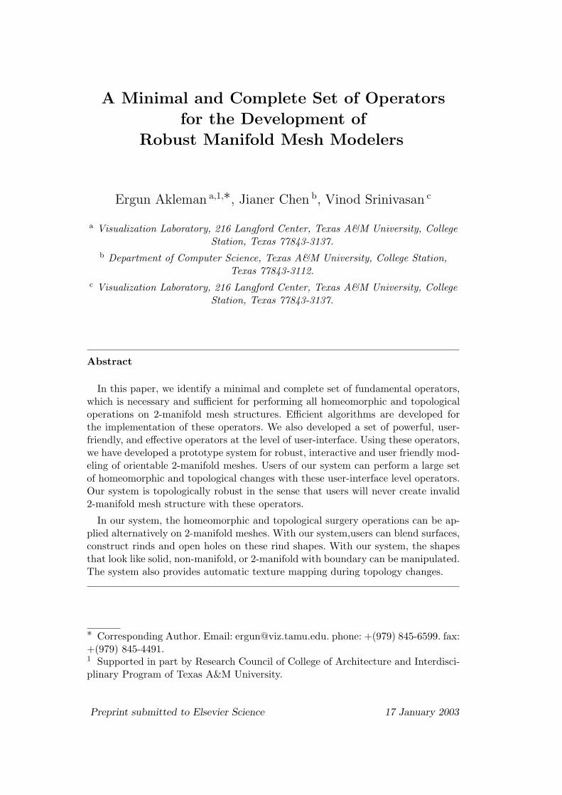
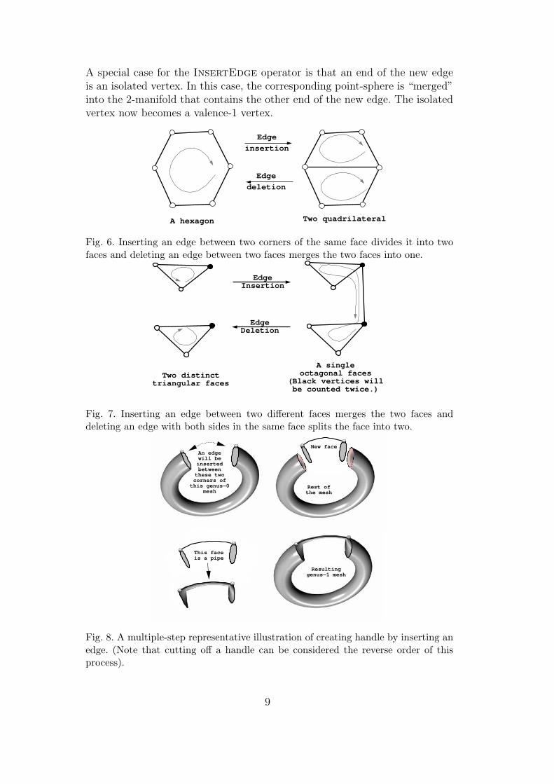
We have introduced the operators InsertEdge and DeleteEdge earlier [1].If InsertEdge Inserts an edge between two corners of the same face, the newedge divides the face into two faces, as shown in Figure 6. On the other hand,if InsertEdge inserts an edge between corners of two different faces (thisincludes the situation in which an endpoint or both endpoints of the new edgecorrespond to point-spheres), the new edge merges the two faces into one. Thissituation is shown in Figure 7. The InsertEdge is the only operator amongthe four basic operators that can increase the genus of a surface.
In case the operator InsertEdge is inserting an edge e to corners of twodifferent faces f1 and f2, there is an interesting and intuitive interpretation ofthe operation as follows: the operation can be decomposed into two steps. Inthe first step, we cut off along the boundaries of the faces f1 and f2, whichresults in a 2-manifold with two “open” holes, then the second step runs anew “pipe” between the two holes and allows the pipe ends to “seal” the twoholes. An illustration is shown in Figure 8.
2 It is not Euler operator since our data structure DLFL unlike half-edge datastructure [24] does not keep track of shells, which are connected manifolds.
8
A special case for the InsertEdge operator is that an end of the new edgeis an isolated vertex. In this case, the corresponding point-sphere is “merged”into the 2-manifold that contains the other end of the new edge. The isolatedvertex now becomes a valence-1 vertex.
A hexagon Two quadrilateral
Edge
insertion
Edge
deletion
Fig. 6. Inserting an edge between two corners of the same face divides it into twofaces and deleting an edge between two faces merges the two faces into one.
Two distinct triangular faces
A single octagonal faces
(Black vertices will be counted twice.)
Edge Deletion
Edge Insertion
Fig. 7. Inserting an edge between two different faces merges the two faces anddeleting an edge with both sides in the same face splits the face into two.
An edgewill be
inserted between
these twocorners of
this genus−0mesh
New face
Rest of the mesh
This faceis a pipe
Resulting genus−1 mesh
Fig. 8. A multiple-step representative illustration of creating handle by inserting anedge. (Note that cutting off a handle can be considered the reverse order of thisprocess).
9
DeleteEdge is the inverse operator of the InsertEdge. As shown in Fig-ure 6 and Figure 7, DeleteEdge either merges two faces into a bigger faceor splits a face (which forms a pipe) into two faces. Similarly, when Dele-teEdge splits a face into two faces (as shown in Figure 7), the situation canbe described by a 2-step process in which the first step cuts off a pipe fromthe 2-manifold and leaves two open holes. The second step seals the two openholes by two disks (which are the two new faces).
An important function of the DeleteEdge operator is to split a surface intotwo surfaces. If the DeleteEdge operator on an edge e = [v1, v2] completelydisconnects the vertices v1 and v2 so that there is no further path connectingthe vertices v1 and v2 in the mesh, then the surface that contains both verticesv1 and v2 is actually split into two disjointed surfaces, one containing vertexv1 and the other containing vertex v2.
A special case of this situation is when an end of the edge e is a valence-1vertex. In this case, an isolated vertex, thus an invisible small point-sphere iscreated. This special case has been dealt with carefully in our implementation.
4 User-Interface Level Operators
The minimal set of fundamental operators is built at the implementation levelof the extended DLFL structure, and may not be effectively visible at the userinterface level because current computer graphics hardware do not provideadequate visual support. For instance, the shape of a handle or a hole thatis created by the InsertEdge operator may not be clearly visible in currentgraphics hardware which, if used at user-interface level, would make it difficultto apply subsequent operators. Another example is the operators CreateV-ertex and DeleteVertex. These operators are dealing with infinitely smallpoint-spheres that are difficult for users to detect.
We have developed a set of powerful and effective operators at a high level ofuser-interface, based on the minimal set of fundamental operators. Using theseuser-interface level operators, users can perform a large set of homeomorphicand topological operators effectively on a given 2-manifold structure. More-over, since the operators are constructed based on the basic minimal set offundamental operators, the user-interface system is very robust and topologi-cally secured, in that users will never introduce invalid topological structures(i.e., non-2-manifold structures) to a given 2-manifold structure.
We present a number of examples of user-interface level operators implementedin our extended system as follows.
10
RemoveEdge(e) permits users to remove an edge, and in case isolated ver-tices are resulted after removing the edge, the resulted isolated vertices arealso removed. This operator prevents users from unintentionally leaving un-wanted point-spheres in edge deletion operations. Clearly, the RemoveEdgecan be easily implemented using the fundamental operators DeleteEdgeand DeleteVertex.
As we have discussed in the previous section, when the fundamental opera-tor InsertEdge inserts an edge between corners of two different faces, thegeometric effect in image is that a very small new pipe is run between thetwo faces, which merges the two faces into one. This results in an infinitelythin pipe. Because of the limit of the current graphics hardware, the resultingunconventional face structure is also difficult for users to understand whenthey apply subsequent operations on the mesh structure.
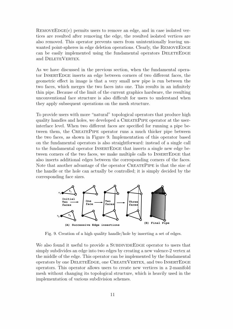
To provide users with more “natural” topological operators that produce highquality handles and holes, we developed a CreatePipe operator at the user-interface level. When two different faces are specified for running a pipe be-tween them, the CreatePipe operator runs a much thicker pipe betweenthe two faces, as shown in Figure 9. Implementation of this operator basedon the fundamental operators is also straightforward: instead of a single callto the fundamental operator InsertEdge that inserts a single new edge be-tween corners of the two faces, we make multiple calls to InsertEdge thatalso inserts additional edges between the corresponding corners of the faces.Note that another advantage of the operator CreatePipe is that the size ofthe handle or the hole can actually be controlled; it is simply decided by thecorresponding face sizes.
(A) Successive Edge insertions(B) Final Pipe
Initial Twofaces
c1
c2
f1
f2
Oneface
Twofaces
Threefaces
Fig. 9. Creation of a high quality handle/hole by inserting a set of edges.
We also found it useful to provide a SubdivideEdge operator to users thatsimply subdivides an edge into two edges by creating a new valence-2 vertex atthe middle of the edge. This operator can be implemented by the fundamentaloperators by one DeleteEdge, one CreateVertex, and two InsertEdgeoperators. This operator allows users to create new vertices in a 2-manifoldmesh without changing its topological structure, which is heavily used in theimplementation of various subdivision schemes.
11
Various CreatePolyhedra operator are also developed and implemented.Using the CreatePolyhedra operators, users are able to create regularpolyhedra, such as cubes, tetrahedra, octahedra, icosahedra, dodecahedra andpolyhedral torii.
Various Subdivision schemes are also developed and implemented. Using theSubdivision schemes, users can apply a variety of subdivision schemes toa 2-manifold mesh, including a number of vertex-insertion schemes, such asCatmull-Clark scheme [8] and, a number of corner-cutting schemes, such asDoo-Sabin scheme [12].
5 Prototype System
Our system is implemented in C++ and fltk. All our interactive examples arerunning on SGI-O2. Our interactive renderer supports silhouette, wireframe,and texture mapping. We use a non-photorealistic lighting model for renderingsince it does not leave any part of the object completely in shadow [18]. Allthe images that show wireframe, such as the ones in Figure 11, are screensnapshots from our system.
To create high-quality photorealistic images, we use a commercial modelinganimation system, Maya. The images such as those in Figures 1, 2, 3, and 4are rendered by using Maya’s renderer. The system supports only topologyand homeomorphic operations we discussed in the paper. It does not supportgeometry changes, i.e., it does not let users change the positions of vertices.
Our system can read and write in obj file format and the interaction withMaya is done in obj format. One limitation with this approach is that someof the 2-manifolds we have constructed in our system cannot be representedby obj format. However, the shapes after subdivision become more classicalpolygonal meshes and can be converted in obj file format.
Although it is a polygonal surface modeler, with our system users can createshapes that look like they have been created by a different type of modeler,such as solid or implicit modelers.
One of the unexpected results from user-interaction with our system is thatusers may feel that they are dealing with solid shapes. While using the system,some users perceive polygons as visible portions of solid bricks. Opening a holegives the impression of removing a brick, and creating a handle is like puttinga pipe or brick between two polygons. We show why this impression is formedby the examples given in Figures 10 and 11.
12
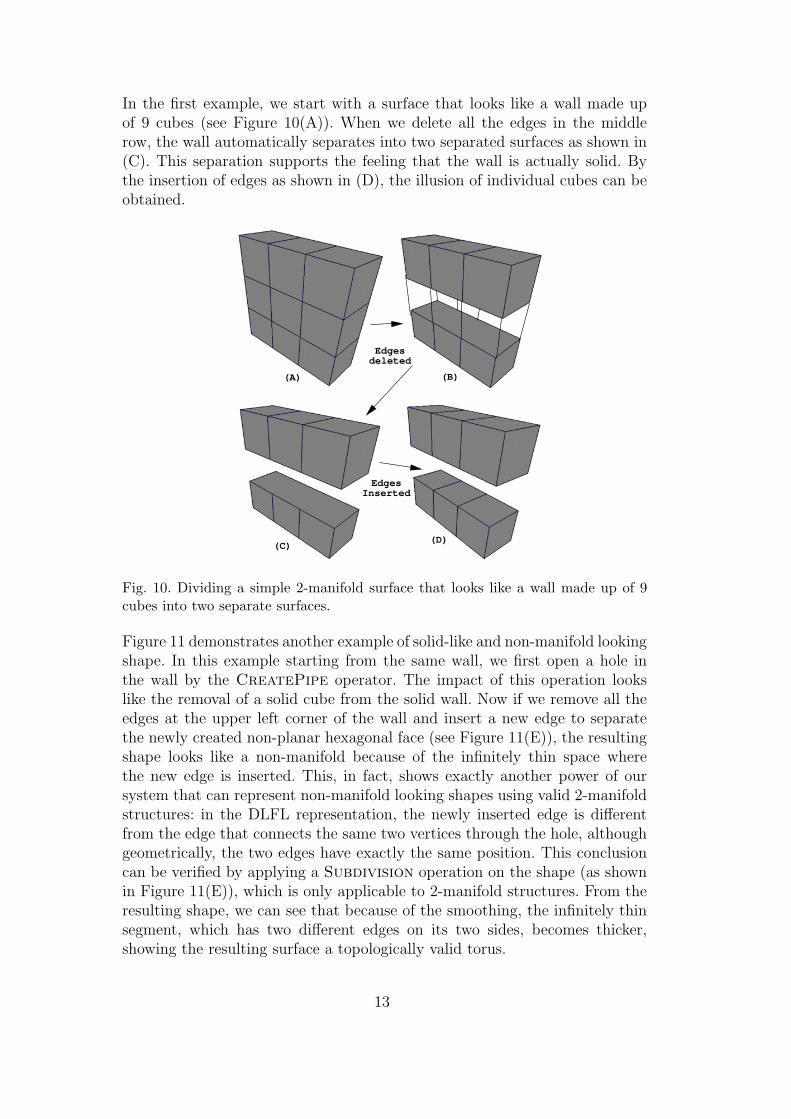
In the first example, we start with a surface that looks like a wall made upof 9 cubes (see Figure 10(A)). When we delete all the edges in the middlerow, the wall automatically separates into two separated surfaces as shown in(C). This separation supports the feeling that the wall is actually solid. Bythe insertion of edges as shown in (D), the illusion of individual cubes can beobtained.
Edges deleted
(C)(D)
Edges Inserted
(A) (B)
Fig. 10. Dividing a simple 2-manifold surface that looks like a wall made up of 9cubes into two separate surfaces.
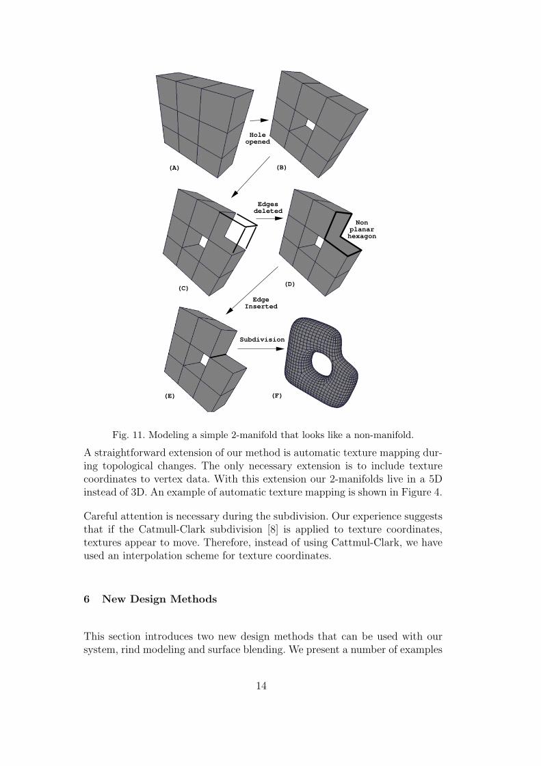
Figure 11 demonstrates another example of solid-like and non-manifold lookingshape. In this example starting from the same wall, we first open a hole inthe wall by the CreatePipe operator. The impact of this operation lookslike the removal of a solid cube from the solid wall. Now if we remove all theedges at the upper left corner of the wall and insert a new edge to separatethe newly created non-planar hexagonal face (see Figure 11(E)), the resultingshape looks like a non-manifold because of the infinitely thin space wherethe new edge is inserted. This, in fact, shows exactly another power of oursystem that can represent non-manifold looking shapes using valid 2-manifoldstructures: in the DLFL representation, the newly inserted edge is differentfrom the edge that connects the same two vertices through the hole, althoughgeometrically, the two edges have exactly the same position. This conclusioncan be verified by applying a Subdivision operation on the shape (as shownin Figure 11(E)), which is only applicable to 2-manifold structures. From theresulting shape, we can see that because of the smoothing, the infinitely thinsegment, which has two different edges on its two sides, becomes thicker,showing the resulting surface a topologically valid torus.
13
(A) (B)
Edges deleted
(C)(D)
Nonplanarhexagon
Edge Inserted
(E) (F)
Subdivision
Holeopened
Fig. 11. Modeling a simple 2-manifold that looks like a non-manifold.
A straightforward extension of our method is automatic texture mapping dur-ing topological changes. The only necessary extension is to include texturecoordinates to vertex data. With this extension our 2-manifolds live in a 5Dinstead of 3D. An example of automatic texture mapping is shown in Figure 4.
Careful attention is necessary during the subdivision. Our experience suggeststhat if the Catmull-Clark subdivision [8] is applied to texture coordinates,textures appear to move. Therefore, instead of using Cattmul-Clark, we haveused an interpolation scheme for texture coordinates.
6 New Design Methods
This section introduces two new design methods that can be used with oursystem, rind modeling and surface blending. We present a number of examples
14
to illustrate these methods.
6.1 Rind Modeling
By using our system it is easy to create shells that are similar to a coconuthusk and open holes on this husk. The procedure is as follows: (1) Duplicatethe mesh and scale the new mesh so that it will completely be inside of the firstmesh (if the object is not convex or star, it may be necessary to furhter movethe positions of some vertices). This operator creates two nested surfaces. (2)Reverse the normals of the smaller second mesh. This operator changes the in-side and outside of a 2-manifold mesh by changing the rotation orders of faces.(3) Connect any two corresponding faces by using the CreatePipe operator.This operator connects two surfaces and makes them a single surface. Then,additional holes can be created by opening more holes using the CreatePipeoperator.
Figure 12 demonstrates two different models created by our rind modeling.The initial mesh is two nested truncated icosahedra shown in (A). (The inner(unseen) truncated icosahedron’s normals are reversed). (B) shows 12 pentag-onal holes. Note that although there are 12 pentagonal holes, the shape in (B)has genus 11 – the first CreatePipe operator does not increase genus sinceit actually connects two genus-0 surfaces. (C) shows a genus-41 surface thatis obtained by application of a corner-cutting scheme [3] and then openingrectangular holes. The resulting shape after subdivision is shown in (D). Fig-ure (E) shows a genus-31 surface that is obtained by opening a hole for eachof the pentagonal and hexagonal faces. Note that this surface also looks likenon-manifold. However, after subdivision, as shown in (F), the real structurebecomes visible. The shapes in (F) and (D) are used in the creation of theobject shown in Figure 1. (F) is the outer surface and (D) is the inner sur-face. The one in between created by first applying corner-cutting subdivisionscheme to the surfaces in (A) and then opening pentagonal and hexagonalholes.
The shapes in Figure 2 were also created as rinds. In that case, first an initialface was created and duplicated. Then, we created a mask and opened holesin the positions of the eyes, mouth and nostrils. After we finished the mask,the outer shell was designed by opening many holes. The teapot in Figure 3was also created using the same method.
We would also like to point out that surfaces that look like 2-manifold withboundary can be created with a modified version of this method: 1) duplicatethe mesh; 2) reverse the normals of the new mesh; and 3) get rid of some facesby opening holes.
15
Pentagonalholes created
Corner-cuttingsubdivisionand rectangular holes created
Catmull-Clarksubdivisionand rendering
All faces become holes
Catmull-Clarksubdivisionand rendering
(A) (B)
(C)(D)
Fig. 12. Example of modeling a rind shape.
6.2 Surface Blending
Users of our system can also create implicit-like blending between surfaces bythe following procedure: first connect the surfaces by connecting two nearestfaces by the CreatePipe operator, then apply a subdivision scheme. If nec-essary, the faces can be remeshed by adding, deleting and subdividing edgesto achieve a blended look before applying subdivision.
Figure 4 demonstrate implicit-like blending. In this example, we start with
16
two truncated icosahedra 3 and connect the two nearest pentagons by theCreatePipe operator. Then, we apply Catmull-Clark subdivision [8] to bothinitial two truncated icosahedra and connected surface to get two images inFigure 4.
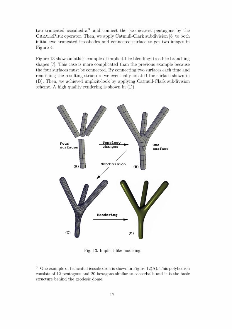
Figure 13 shows another example of implicit-like blending: tree-like branchingshapes [7]. This case is more complicated than the previous example becausethe four surfaces must be connected. By connecting two surfaces each time andremeshing the resulting structure we eventually created the surface shown in(B). Then, we achieved implicit-look by applying Catmull-Clark subdivisionscheme. A high quality rendering is shown in (D).
Foursurfaces
Topology changes One
surface
Subdivision
Rendering
(A) (B)
(C) (D)
Fig. 13. Implicit-like modeling.
3 One example of truncated icosahedron is shown in Figure 12(A). This polyhedronconsists of 12 pentagons and 20 hexagons similar to soccerballs and it is the basicstructure behind the geodesic dome.
17
7 Conclusion and Future Work
Note that based on our minimal set of operators it is easy to expand thecapabilities of the system. In fact, homeomorphic operations that are applica-ble in our extended class are not just limited to regular subdivision schemes,any homeomorphic operation over 2-manifold shapes can be effectively imple-mented using our minimal-set.
In this paper, we have introduced new topological entities for effectively ma-nipulating 2-manifold mesh structures. We have identified a minimal set offundamental operators, which is necessary and sufficient for performing allhomeomorphic and topological operators on 2-manifold mesh structures. Wedeveloped a system in which extremely efficient algorithms for these operatorsare implemented. A set of powerful, user-friendly, and effective operators hasalso been developed at the level of user-interface, based on the fundamen-tal operators. Users of our system can perform a large set of homeomorphicand topological changes with these user-interface level operators. Moreover,because our system is based on an extended DLFL structure that always guar-antees a valid 2-manifold structure, it is topologically robust in the sense thatusers will never create invalid 2-manifold mesh structure with these operators.
We have also introduced a number of methods, e.g., surface blending and rindmodeling, to create shapes with the new modeler. By using these methods, wehave constructed a wide variety of shapes that cannot easily be constructedotherwise.
Our work has shown that the system is also powerful and practical in manipu-lating non-manifold looking shape structures. We have presented examples, inwhich many shapes that are not conventionally considered to have a 2-manifoldrepresentation can have 2-manifold representations and can be constructed byour modeler.
We are planning to introduce new methods and develop high-level operatorsfor these methods. Such high-level operators can be useful not only in model-ing but also in other fields of computer graphics. For instance, blending can beused in physical based modeling to represent interacting liquid particles. An-other possible usage of our approach is mesh compression. Since our extendedstructure provides DeleteEdge and DeleteVertex operators to simplifythe topology of a given mesh, these topology simplifications can be used toobtain better and more efficient simplifications of meshes. Moreover, our ap-proach can also be used to develop algorithms to provide morphs betweenpolygonal meshes of different genii.
18
8 Acknowledgments
We are grateful to Donald H. House, David Romei and Mark Clayton for theirvaluable comments. We would also like to thank Sajan Skaria for initial facialmodel that is used to create the shape shown in Figure 2. Glen Vigus andChristina Haaser helped us to edit the video that shows an interactive session.
References
[1] E. Akleman and J. Chen, “Guaranteeing the 2-Manifold Property for mesheswith Doubly Linked Face List”, International Journal of Shape ModelingVolume 5, No 2, pp. 149-177.
[2] E. Akleman, J. Chen, and V. Srinivasan, “A New Paradigm for ChangingTopology During Subdivision Modeling,” Pacific Graphics 2000, October 2000,pp. 192-201.
[3] E. Akleman, J. Chen, F. Eryoldas and V. Srinivasan, “Handle and HoleImprovement with a New Corner Cutting Scheme with Tension,” ShapeModeling 2001, May 2001, pp. 183-192.
[4] G. Barequet and S. Kumar, “Repairing CAD models”, in Proceedings of IEEEVisualization’97, (October 1997) pp. 363-370.
[5] B. J. Baumgart, “Winged-edge polyhedron representation”, Technical ReportCS-320, Stanford University, 1972.
[6] J. I. Blinn, “A Generalization of Algebraic Surface Drawing”, ACM Transactionon Graphics, vol 1, no. 3, pp. 235-256, 1982.
[7] J. Bloomenthal, “Modeling the Mighty Apple”, Computer Graphics, vol 19, no.3, pp. 305-311, 1985.
[8] E. Catmull and J. Clark, “Recursively generated B-spline surfaces on arbitrarytopological meshes”, Computer Aided Design, 10 (September 1978) 350-355.
[9] J. Chen, D. Archdeacon, and J. Gross, “Maximum genus and connectivity”,Discrete Mathematics, 149 (1996) 19-29.
[11] J. Chen and E. Akleman, “Topologically Robust Mesh Modeling: Concepts,Data Structures and Operations”, In Preparation.
[12] D. Doo and M. Sabin, “Behaviour of recursive subdivision surfaces nearextraordinary points”, Computer Aided Design, 10 (September 1978) 356-360.
19
[13] J. Edmonds, “A Combinatorial Representation for Polyhedral Surfaces”,Notices American Mathematics Society, 7 (1960) 646.
[14] H. Ferguson, A. Rockwood and J. Cox, “Topological Design of SculpturedSurfaces”, Computer Graphics, 26 (August 1992) 149-156.
[15] P. A. Firby and C. F. Gardiner, Surface Topology, (John Wiley & Sons, 1982).
[16] A. T. Fomenko and T. L. Kunii, Topological Modeling for Visualization,(Springer-Verlag, New York, 1997).
[17] J. L. Gross and T. W. Tucker, Topological Graph Theory, (Wiley Interscience,New York, 1987).
[18] A. Gooch, B. Gooch, P. Shirley and E. Cohen, “A Non-Photorealistic LightingModel For Automatic Technical Illustration”, Computer Graphics, vol 32, no.3, pp. 447-452, 1998.
[19] L. Guibas, J. Stolfi, “Primitives for the manipulation of general subdivisions andcomputation of Voronoi diagrams”, ACM Transaction on Graphics, 4 (1985)74-123.
[20] L. Heffter, “Uber das Problem der Nachbargebiete”, Math. Annalen, 38 (1891)477-508.
[21] C. M. Hoffmann, Geometric & Solid Modeling, An Introduction, (MorganKaufman Publishers, Inc., San Mateo, Ca., 1989).
[22] C. M. Hoffmann and G. Vanecek, “Fundamental techniques for geometricand solid modeling”, Manufacturing and Automation Systems: Techniques andTechnologies, 48 (1990) 347-356.
[23] M. Karasick, “On the representation and manipulation of rigid solids”, Ph.D.Thesis, McGill University, 1988.
[24] M. Mantyla, An Introduction to Solid Modeling, (Computer Science Press,Rockville, Ma., 1988).
[25] T. M. Murali and T. A. Funkhouser, “Consistent solid and boundaryrepresentations from arbitrary polygonal data”, in Proceedings of 1997Symposium on Interactive 3D Graphics , (1997) pp. 155-162.
[26] . G. Vanecek, “Set operations on polyhedra using decomposition methods”,Ph.D. Thesis, University of Maryland, 1989.
[27] K. Weiler “Polygon comparison using a graph representation”, ComputerGraphics, 13 (August 1980) 10-18.
[28] K. Weiler, “Topological structures for geometric modeling”, Ph.D. Thesis,Rensselaer Polytechnic Institute, N. Y., August 1986.
[29] G. Wyvill, C. McPheeters, and B. Wyvill, “Data Structure for Soft Objects”,The Visual Computer, vol 2, no. 4, pp. 227-234, 1997.
[30] D. Zorin and P. Schroder, editor, Subdivision for Modeling and Animation, ACMSIGGRAPH’2000 Course Notes no. 23, July, 2000.