+ All Categories
Home > Documents > A Mixed Multi-Field Finite Element Formulation for ... · Formulation for Thermopiezoelectric...

A Mixed Multi-Field Finite Element Formulation for ... · Formulation for Thermopiezoelectric...

Date post: 23-May-2018
Category:
Upload: vominh
View: 220 times
Download: 1 times
Share this document with a friend
28
NASA / TM--1999-000000 A Mixed Multi-Field Finite Element Formulation for Thermopiezoelectric Composite Shells Ho-Jun Lee Glenn Research Center, Cleveland, Ohio Dimitris A. Saravanos Ohio Aerospace Institute, Cleveland, Ohio Prepared for the Sixth Annual International Symposium on Smart Structures and Materials sponsored by the International Society for Optical Engineering Newport Beach, California, March 1-5, 1999 National Aeronautics and Space Administration Glenn Research Center May 1999 https://ntrs.nasa.gov/search.jsp?R=19990047779 2018-06-28T07:40:29+00:00Z
Transcript

NASA / TM--1999-000000

A Mixed Multi-Field Finite Element

Formulation for Thermopiezoelectric

Composite Shells

Ho-Jun Lee

Glenn Research Center, Cleveland, Ohio

Dimitris A. Saravanos

Ohio Aerospace Institute, Cleveland, Ohio

Prepared for theSixth Annual International Symposium on Smart Structures and Materials

sponsored by the International Society for Optical Engineering

Newport Beach, California, March 1-5, 1999

National Aeronautics and

Space Administration

Glenn Research Center

May 1999

https://ntrs.nasa.gov/search.jsp?R=19990047779 2018-06-28T07:40:29+00:00Z

NASA Center for Aerospace Information7121 Standard Drive

Hanover, MD 21076Price Code: A03

Available from

National Technical Information Service

5285 Port Royal Road

Springfield, VA 22100Price Code: A03

A MIXED MULTI-FIELD FINITE ELEMENT FORMULATION

FOR THERMOPIEZOELECTRIC COMPOSITE SHELLS

Ho-Jun Lee

National Aeronautics and Space AdministrationLewis Research Center

Cleveland, Ohio 44135

and

Dimitris A. Saravanos*

Ohio Aerospace Institute

Brook Park, Ohio 44142

ABSTRACT

Analytical formulations are presented which account for the coupled mechanical, electrical, and

thermal response of piezoelectric composite shell structures. A new mixed multi-field laminate

theory is developed which combines "single layer" assumptions for the displacements along

with layerwise fields for the electric potential and temperature. This laminate theory is

formulated using curvilinear coordinates and is based on the principles of linear

thermopiezoelectricity. The mechanics have the inherent capability to explicitly model both the

active and sensory responses of piezoelectric composite shells in thermal environments. Finite

element equations are derived and implemented for an eight-noded shell element. Numerical

studies are conducted to investigate both the sensory and active responses of piezoelectric

composite shell structures subjected to thermal loads. Results for a cantilevered plate with an

attached piezoelectric layer are compared with corresponding results from a commercial finite

element code and a previously developed program. Additional studies are conducted on a

cylindrical shell with an attached piezoelectric layer to demonstrate capabilities to achieve

thermal shape control on curved piezoelectric structures.

INTRODUCTION

The potential performance advantages from utilizing smart structural components in advanced

aerospace applications has lead to the extensive recent development of both analytical and

experimental methods to characterize the behavior of these materials. Crawley (1994), Rao and

Sunar (1994), and Rogers (1993) provide detailed overviews of smart structure technologies.

Piezoelectric materials represent one of the more common materials currently being investigated

for smart structures applications due to their inherent capability to be utilized as both actuators

and sensors. Of practical interest are curved piezoelectric composite shells, since these

configurations are most commonly used in various aerospace structural applications. In

* NASA Resident Research Associate at Lewis Research Center

addition,mostaerospaceapplicationsinvolveoperationsin changingthermalenvironments.Thus,in orderto effectivelyandaccuratelycharacterizetheresponseof smartstructureswithpiezoelectricmaterials,thecouplingeffectsfrom boththecurvilineargeometryandthermopiezoelectricitymustbeaccountedfor in theanalysis.

Numeroustheoriesandmodelshavebeenproposedto analyzepiezoelectriccompositebeams,plates,shells,andsolids. SaravanosandHeyliger(1998)provideacomprehensivereviewandclassificationof theseanalyticalmodels,consequentlyonly abrief reviewconcerningpiezoelectricshellsis providedherein. Docmeci(1990)investigatedthevibrationof singlelayeredpiezoelectricshells. Lammering(1991)developedaReissner-Mindlinsheardeformableshell finite element,while TzouandGadre(1989)derivedequationsfor thin piezoelectricshellsbasedon theKirchoff-Love hypothesis.Shellformulationsandfinite elementswhichexplicitlyaccountfor thepiezoelectriccouplinghavealsobeenreported.Tzou and Ye (1996) modeled

piezoelectric shells as a layerwise assembly of triangular elements. Heyliger et al. (1996)

developed a discrete-layer laminated piezoelectric shell element. Saravanos (1997) implemented

a mixed shear-layerwise theory for piezoelectric shells.

Limited research has been performed to assess the implications of thermal effects on

piezoelectric composite shells. Tauchert (1992) constructed a piezoelectric plate theory for

thermal behavior based on Kirchoff's assumptions in which the charge equation was not

considered. Rao and Sunar (1993) developed a general finite element formulation for

thermopiezoelectric plates. Yzou and Howard (1994) and Tzou and Bao (1995) postulated

consistent, yet uncoupled, formulations for thin, shallow thermopiezoelectric shells based on

classical laminate theory assumptions. Chandrashekhara and Kolti (1995) presented an

uncoupled first-order shear finite element formulation for shallow piezoelectric composite shells

under thermal loads. Tzou and Ye (1994) developed a three-dimensional finite element for thin

thermopiezoelectric solids. Tzou and Bao (1997) included large-rotation geometric nonlinearity

into their previously developed uncoupled models for thermal piezoelectric shells. Lee and

Saravanos (1996, 1997) developed electromechanically coupled mechanics and finite elements

for thermal laminated composite piezoelectric beams and plates, respectively, which use

layerwise approximations for the displacements, electric potentials and temperature fields. Exact

solutions for specific configurations of thermopiezoelectric plates and cylindrical shells have

been reported by Dube et al. (1996a, 1996b), Xu and Noor (1996), Xu et al. (1997) and Choi etal. (1997).

Generally, most of the works described use approximate uncoupled models to account for the

behavior of thermopiezoelectric laminated shells. However, neglecting the piezoelectric

coupling that arises from the pyroelectric and thermal expansion coefficients can lead to

substantial errors in predicting the structural response. Thus, this paper presents a coupled

piezoelectric shell theory which incorporates thermal effects and has the capability to accurately

predict the mechanical, electrical, and thermal response of thin and intermediately thick

piezoelectric composite shells. The coupled behavior is captured at the material level through

the thermopiezoelectric constitutive equations and the governing equations are formulated and

2

solvedin curvilinearcoordinates.Themechanicsincorporatedifferenttypesof through-the-thicknesskinematicapproximationsfor all field variables.First-ordersheartheoryassumptionsareusedfor thedisplacements,whilediscrete-layertheoryapproximationsareimplementedfortheelectricpotentialandtemperature.Thecombinationof mixedthrough-the-thicknessapproximationsfor thedisplacement,electricpotentialandtemperatureis a uniquefeatureof the"mixedpiezothermoelasticshelltheory"(MPST)whichenablestheaccurateanalysisof thin andmoderatelythick piezoelectricshells.

THERMOPIEZOELECTRIC LAMINATED SHELLS

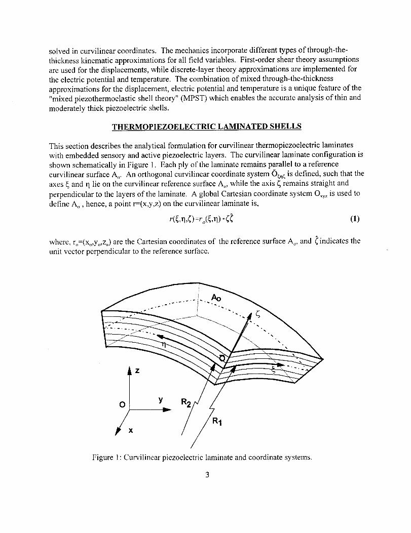
This section describes the analytical formulation for curvilinear thermopiezoelectric laminates

with embedded sensory and active piezoelectric layers. The curvilinear laminate configuration is

shown schematically in Figure 1. Each ply of the laminate remains parallel to a reference

curvilinear surface A o. An orthogonal curvilinear coordinate system 0_n _ is defined, such that the

axes _ and q lie on the curvilinear reference surface A o, while the axis _ remains straight and

perpendicular to the layers of the laminate. A global Cartesian coordinate system Oxyz is used to

define Ao, hence, a point r=(x,y,z) on the curvilinear laminate is,

(1)

where, ro=(Xo,Yo,Zo) are the Cartesian coordinates of the reference surface A,,, and _ indicates the

unit vector perpendicular to the reference surface.

0

/x

Z

R1

,

°°.°.

-,

Figure 1: Curvilinear piezoelectric laminate and coordinate systems.

Governing Material Equations

Each ply is assumed to consist of a linear piezoelectric material with properties defined in the

orthogonal curvilinear system O_n_, with constitutive equations of the following form,

o i : coESI- e ikEk - _iOs (2)

D t : eoS + el_ k + pk 0

where: i, j = 1 .... ,6 and k, 1= 1,...,3; o_ and S i are the mechanical stresses and engineering strains

in vectorial notation; E k is the electric field vector; Dt is the electric displacement vector; C,j is

the stiffness tensor; e0 is the piezoelectric tensor; 8/k is the electric permittivity tensor of the

material; _._is the thermal expansion vector; 0 = AT = T - T Ois the temperature difference from

the thermally stress fi'ee reference temperature To; and Pk is the pyroelectric vector. Superscripts

E and S indicate constant electric field and strain conditions, respectively. The axes 1, 2, and 3 of

the material are parallel to the curvilinear axes _, rl, and _, respectively. The materials are

assumed to be monoclinic class 2 crystals with a diad axis parallel to the z axis (Nye, 1964). The

assumed material class is general enough, such that Eqs. (2) may encompass the behavior of off-

axis homogenized piezoelectric plies, as well as the passive composite plies. The tensorial strain

S,j and electric field components in a curvilinear coordinate system are related to the

displacements and electric potential, respectively (Saravanos, 1997).

Mixed Multi-Field Laminate Theory_

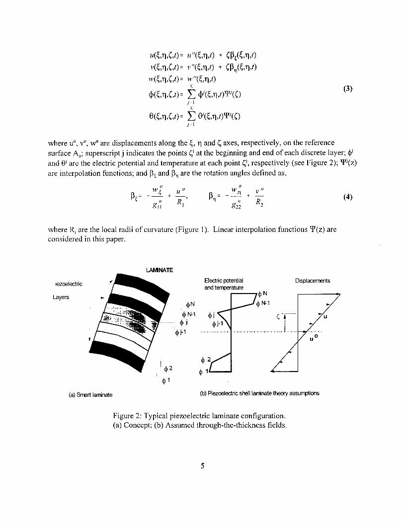
The proposed thermopiezoelectric shell theory combines linear displacement fields through the

thickness of the laminate for the displacements u and v (along the _ and 1"1axes respectively) with

layerwise electric potential and temperature fields through the laminate, consisting of N discrete

continuous segments (see Figure 2). Previous works by Lee and Saravanos (1996, 1997) on

layerwise theories for thermal piezoelectric beams and plates have demonstrated the advantages

and necessity of layerwise approaches for capturing the complex electric fields and interactions

which are present in piezoelectric actuators and sensors. Consequently, the present mixed

piezothermoelastic shell theory (MPST) will entail the capability to (1) accurately and efficiently

model thin and moderately thick laminated piezoelectric shells with arbitrary laminations and

electric configurations, (2) capture the through-the-thickness electric heterogeneity induced by

the embedded piezoelectric sensors and actuators, and (3) represent the changing thermal

gradients through the laminate plies.

The discrete-layer kinematic assumption effectively subdivides the laminate into N-1

sublaminates (or discrete-layers). A continuous linear electric potential and temperature variation

is assumed in each sublaminate, such that a C,, continuity results through-the-thickness of the

laminate (see Figure 2). In this formulation, the subdivision can be arbitrarily altered according

to the configuration of the piezoelectric layers or the desired level of approximation. Thus, the

resulting "zig-zag" shape of the approximation can be a-priori controlled to vary the detail of

approximation from a single-layer to a finely graded field. The various field variables are

approximated by the following form,

4

.(_,q,¢,0-- u°(Ln,t) + ¢13_(_,n,0,O

v(_,rl,¢,t)= v (¢,rl,t) + ¢13,1(_,rl,t)

w(_,q,_,t) = w "(_,rl,t )N

,b(_.n,¢,0= _ _(_,n,0'eJ(¢)j' I

0(¢,q,¢,t)= _ 0,(¢,n,t)_J(¢))-I

(3)

where u °, v °, w ° are displacements along the _, r I and _ axes, respectively, on the reference

surface Ao; superscript j indicates the points _i at the beginning and end of each discrete layer;

and 0 i are the electric potential and temperature at each point _J, respectively (see Figure 2); _J(z)

are interpolation functions; and 13¢and 13_are the rotation angles defined as,

O O

W,_ U o V o[3_- + , [3n- w"l +- (4)

o R o R2gtl l g22

where R, are tile local radii of curvature (Figure I). Linear interpolation functions _(z) are

considered in this paper.

iezoelectdc

Layers

(a) Smart laminate

LAMINATE

4 1

Electdc potential

and temperature

_N

_J_j-1 .................

Displa_nts

................ |

/(b) Piezoelectric shell laminate theory assumptions

Figure 2: Typical piezoelectric laminate configuration.

(a) Concept; (b) Assumed through-the-thickness fields.

TheLove'sassumptionfor shallowshellsis furtherimplemented,i.e.the local radii of the shell

are substantially higher than the thickness (h/R, << 1), yielding (1+ _R_ _- 1). In the context of

Eqs. (3), the engineering strains become

S_(_,rl,_,t) = S,°(_,rl,t) +( k,(_,TI,t) i= 1,2,6

s3(_,n,_,t): 0 (5)

S,(_,,q,_,t) = S,°(_,rl,t) i=4,5

where S° and k are the strain and curvatures at the reference surface, defined as follows:

O O

S,O=_J_ju _ + g, ,.n v O) w ° S o 1 .v O+gZ2._ w °-- +--' 0

gll g22 RI 2 =---_( ,n --u o)+__o g22 gll R2

o o

• --7 ,n ----o-gll g2z g22 gll

o o

11,,rI y o W,_ _t o

o R2 o Rig22 gll

(6)

O o

, + --Tv_,gll g22 g22 gll

O O

o - --7 ,1gll g22 g22 gll

(7)

where R, are the local radii of curvature, and ," og ,,, g 22are the components of the metric tensor on

the surface A o (_=0) defined as o :_X 2 2 2 o ] 2 2 2gl I o._+Yo._+Zo._ and g22 =_Xo.n +Yo.n +Zo.n

The electric field vector also becomes,

N

E_(_,q,_,t) = y]_ E/(_,rl,t)t_J(_)j=l

N

E3(_,n,_,t)= Y_ EJ(_,TI,t)_J¢(_)j=l

i=1,2

(8)

where _zi_ is the generalized electric field vector defined as:

E(-- E;-- E;=-eO o

gll g22(9)

Equations of Motion

The variational form of the equations of motion in the orthogonal curvilinear system is,

f / -6H(S,E)-6T }loqd_d_ld( + f 6u,re,+ f 6O_dS : oFs Fl_

(10)

where 6H is the variation of the electric enthalphy and 6T the variation of the kinetic energy,

defined as,

6H : 6S, o, - 6EkD k : 6SCvS- 6S e,lEl- 6Si_.,0 - 6EkeksS - 6EkektE l - 6Ed) kO(11)

6 T = -6uip,fi i

where Yand/) are the surface tractions and electric displacement acting on surfaces P s and P D,

respectively

zi=o0t// /)=Dr/j id"= 1..... 3 (12)

[J] is the Jacobian matrix of the transformation between the global cartesian and curvilinear

system. For the curvilinear system 0_,1_ the determinant of the Jacobian takes the form:

=lO(x,y,z) o ,, o oId] _ = gllg22( 1 +(/RI)(1 +(/R2)=gllg22 (13)

It is now possible to rearrange the variational statement and separate the through-the-thickness

integration, as follows:

L,-(6HL(S,E)-6TL)d{drl + fr(6Uf¥, +6qb/_)dI'=O (14)

where A o is the curvilinear reference surface, _ and L) are the surface tractions and electric

displacement on the boundary surface F; 8H L and 8T L are the variations of the electric enthalpy

and kinetic energy of the laminate, defined as

h 6H,6T> gl 1g22 d_ (15)<6HL,aTL>= f_ < o o

7

and h is the laminate thickness. By combining Eqs. (11) and (15) and integrating through-the-

thickness, the variation of the "electric enthalpy of the piezoelectric laminate is obtained as a

quadratic expression of the generalized strain, electric field, and the generalized laminate

matrices,

_)HL o o o o: 6S, AiS j +6S, B,k+6k.B.S, +6k,D,k. -tJ y J J J tJ j

N

-Zm=l

N

-F_,m= l

N No --m m m --m o ^ m m m ^ m m mn m

( 5s, E,,&. E;S, +8 U)e, + E3E)k) G,,¢m=l n=l

N N

( _Si°Amom+_)omAmsi °+_kAmOm+_)OmAmk') -Z Z _)Ekmekmnomt t j j j j

m=l n=l

(16)

In the above equation, [A], [B], and [D] are the stiffness matrices; [E m] overbar and overhat are

the piezoelectric matrices; and [G m"] are the matrices of electric permittivity of the curvilinear

laminate described by Saravanos (1997).

The generalized thermal matrices are new, and include the thermal expansion matrices

[A"'] overbar and overhat,

L

< _k",,A m, > -- &°tg2°2 Y_ 1"¢"' X,W"(¢)<I,_>d_, i=1,2 (17)/: 1 0_1

and the pyroelectric laminate matrices [pro,],

L

,,,,, : g Og o re.,P, 11 22 Z Pl, W"(('l_(Od( " ,/=1 d_l

L

p ,,,n g Og o F ¢.13 : .. 22 _ p_W,_(¢)W'(Od("1:1 d_l

k:l,2

(18)

where L is the number of plies in the laminate.

The kinetic energy of the laminate takes the form,

_),.,,., _. o A.o o B B. D"

I L:Obl I _)tbli +6ll J pj_j.+6_j.pjltj+6_jpa. _a, i:1 .... ,3, j:1,2 (19)

where u°u {u°,v°,w °} and [3i={[3_, [3n}; 9 A, p B, p D are the generalized densities, expressing the

mass, mass coupling and rotational inertia per unit area of the laminate (Saravanos, 1997).

Finite Element Formulation

The previous formulation of the governing equations in the orthogonal curvilinear system and the

generalized variational statement in Eq. (11) enables the development of structural solutions by

using approximations for the generalized multi-field state variables (displacements, rotation

angles,electricpotentialandtemperature)of thefollowing type,M

uj°(_,q,t) = Y: uj°'(t) N '(_,1]), j= ] .... ,3i=1

M

[3j({,rl,t)= y:. [3_(I) N *({,rl), j= 1,2i:1

M

qb"(¢,rl,t ) = _ dp"'(t) N '(¢,rl), m = 1,...,Ni=1

M

om(_3q,t) = _ om_(t) N _(_,rl), m = I .... ,Ni=l

(20)

where superscript i indicates the reference surface displacement, rotation angle and generalized

electric potential components corresponding to the i-th in-plane interpolation function N_(_,q).

Implementation of local interpolation functions in Eqs. (19) results in the finite element based

solutions. Combining Eqs. (6), (7), (9), and (20) results in the strain, electric field and

temperature interpolation matrices. Substituting into the variational equations of motion Eqs.

(14), and collecting the coefficients as mandated by Eqs. (16) and (19), .the governing dynamic

equations of the structure are expressed in the discrete matrix form,

LI'£ q_z,,/ [K;, ]][ { (I)F} J {Qqt)}-[K;g]{(I)A}-[K£bo]{O}I

(21)

Submatrices Kuu, Ku, and K** indicate the elastic, piezoelectric and permittivity matrices; Ku0 and

K,e are the thermal expansion and pyroelectric matrices of the structure; and M,, is the mass

matrix. Superscripts F and A indicate the partitioned submatrices in accordance with the sensory

(free) and active (applied) electric potential components, respectively, as explained previously

(Lee and Saravanos, 1997). Thus, the left-hand side includes the unknown electromechanical

response of the structure {u, 0pF}, i.e. the resultant displacements and voltage at the sensors. The

right-hand includes the excitation of the structure in terms of mechanical loads, applied voltages

qV' on the actuators, applied temperature loads and electric charge at the sensors QF(t).

Based on the above formulation, an eight-noded (M=8) finite element was developed with bi-

quadratic shape functions of the serendipity family. Reduced integration was applied selectively

on the calculation of shear elastic and piezoelectric stiffness terms, as this has been found to

improve the accuracy of the numerical predictions. These discrete equations can be easily

condensated into the following independent equations for the sensory electric potentials,

{q_F} = [K,I,_] , ([K,F_] {_A} + [K,o ] {0} -[K,F,,F] {u} - {O F(t)} ) (22)

and the structural displacements,

9

_.FF FF FF{ +( [X,j - ] ]-' ]) {u} :

FA A{F(t)} -([K,,,FFj [Kgt'_:]-' [K,_F_] + [K_, ]) {_ }+

[Kuo FF] r k- Ff'l-I FF gF -t",l,,l,J {Q g(t)} - ([Kuqb ] [K_0] 1 [X+0] + [K0]) {0}

(23)

NUMERICAL RESULTS AND DISCUSSION

Evaluations of the developed mechanics and applications to various composite structures with

piezoelectric actuators and sensors are presented in this section. In order to represent the location

of the piezoelectric layers, the standard laminate notation is expanded, such that piezoelectric

layers are indicated by the letter p. The properties of both the piezoelectric and composite

material are listed in Table 1. The structural configurations which are studied include a clamped

plate and a circular cylindrical shell.

Clamped Plate

The first case examined consists of a 50.8 mm x 25.4 mm x 5.08mm [0s/p] plate composed of

carbon/epoxy with an attached piezoceramic layer as shown in Figure 3. The plate is clamped on

one side and is subjected to a uniform thermal load of 50°C. The objective of this part of the

numerical study is to verify the accuracy of the current formulation for both the sensory and

active response with corresponding results from a 20-node quadratic piezoelectric continuum

element (MSC/ABAQUS, 1996), as well as a previously developed 4-node plate element (Lee

and Saravanos, 1996) that implements a full layerwise laminate theory. To the author's best

knowledge, the continuum element neglects pyroelectric effects in the piezoelectric formulation,

so the pyroelectric constants were intentionally neglected in both the shell and plate program

analysis during the comparisons with the continuum element. Subsequent studies are performed

using only the plate and shell elements to investigate the influence of incorporating the

pyroelectric effect. Since the three programs utilize different formulations and elements, each

analysis required different finite element meshes. The shell program utilized a 10x5 mesh with

two discrete layers (one for the carbon/epoxy and one for the piezoelectric). A finer 20xl 0 mesh

was used for the 4-noded plate element with two discrete layers. The continumn element

analysis incorporated a 10x5x2 mesh, with the two elements through the thickness of the plate

corresponding to the two discrete layers used in the shell and plate programs. All displacements

(w) and electric potentials (qb) presented in this section are along the centerline of the plate

(y/b=0.5) and are nondimensionalized using the following relationships:

w' --- 100w / h ; qb" = qb d31 105 / h (24)

where h represents the plate thickness and d31 represents the piezoelectric charge constant.

10

TABLE 1: MATERIAL PROPERTIES

Piezoceramic Carbon/Epoxy

Elastic Moduli (10 9 Pa):

Ell

E22

E33

GI2

G13

G23

69.0

69.0

69.0

26.5

26.5

26.5

142.0

10.3

10.3

7.20

7.20

4.29

Poisson's Ratio:

D12

Dt3

U23

0.30

0.30

0.30

0.27

0.27

0.20

Thermal Expansion Coefficient (106/ °C):

C(,II

0_22

1.20

1.20

-0.90

27.0

Piezoelectric Charge Constant (10 12 m/V):

d31 -154.0 0.0

Electric Permittivity (10 -9 farad/m):

Ell = C22 = C3315.05 0.0266

Pyroelectric Constant (I0 "3 coulomb/m 2 °C):

P3 I

Reference Temperature ( °C):

-0.2

To I 200 I

0.0

20.0

11

Y

t///

/

/

///I

Z

0.635 mm

4.445 mm

Top View

i!

Front View

Piezoceramic Carbon/Epoxy

Tb = 25.4 mm

12. x

h = 5.08 mm

1 iJ I li:: X

< a = 50.8 mm >

Figure 3: Geometry of a clamped plate with an attached piezoelectric layer.

i

Sensory Response. The response of the plate with the piezoelectric layer operating as a sensor

is presented in this section. In the sensory mode, the piezoelectric layer is free to develop a

corresponding electric potential in response to the thermally induced deformation of the plate

through the direct piezoelectric effect. The resulting displacements predicted by the three

different codes show almost exact agreement as depicted in Figure 4. The corresponding sensory

electric potential which develops in the piezoelectric layer is shown in Figure 5. Although the

continuum element electric potential results tend to be slightly higher due to the consideration of

the through-the-thickness Poisson's effect, there is good overall agreement between the threeelements.

Active Response. The piezoelectric layer can also be used as an actuator by applying a voltage

differential to the piezoelectric layer and utilizing the converse piezoelectric effect to alter the

thermal distortion of the plate. Figure 6 shows the centerline deflection of the plate for three

different applied electric potentials (qbA'). The three codes show almost exact agreement and

demonstrate the capability to achieve thermal shape control by applying electric voltages.

12

.g

ooo.,_ ...... i-0.10

-0.20

-0.30I

-0.40

Shell

--m-- Plate

Continuum

x/a

Figure 4: Thermally induced sensory displacements of a [OJp] clamped plate.

0.60

-e-

0.45

0.30 _,

0.15 _

0.00 ....... _ ___ L

--e-- Shell

Plate

--_-- Continuum

x/a

Figure 5: Thermally induced sensory electric potentials ofa [0Jp] clamped plate.

13

0.00

-0.10

"_: -0.20

-0.30

_A'=o

-0.400.00 0.20 0.40 0.60 0.80 1.00

x/a

--e-- Shell

--m--- Plate

--_:--- Continuum

Figure 6: Displacements under active electric potentials of a [Os/p] clamped plate.

Pyroelectric Effects. The effect of incorporating the pyroelectric constant (P3) into the analysis

is presented in this section. The previous two cases have neglected the pyroelectric effect in

order to compare with the continuum element. Results for the shell and plate elements are

presented with the piezoelectric layer in a sensory mode. Figures 7 and 8 show the centerline

displacements and the centerline electric potential, respectively. The case with p3=0 represents

the case without considering pyroelectric effects shown in Figures 4 and 5. Both figures show

the almost exact agreement between the plate and shell elements, as well as the significant

impact that pyroelectric effects can have on the displacement and electric potential of a smart

structure operating in changing thermal environments. This significant influence on the

structural response is caused by the coupling introduced by the piezoelectric layer and can be

modeled only through coupled formulations, such as the present one. Uncoupled formulations

are unable to capture this effect and can result in significant errors when modeling thermal

piezoelectric structures.

14

0.00 ...........

P 3 = -2e-4

-0.10

Shell

_: -0.20 - - m- - Plate

-0.30 P3 =/_0

-0.40 ........0.00 0.20 0.40 0.60 0.80 1.00

x/a

Figure 7: Pyroelectric effects on sensory displacements of a [0s/p] clamped plate.

.e-

2.00

P 3 = -2e-4

,50

1.00

I0.50 r

p_ =0

0.00 ................0.00 0.20 0.40 0.60 0.80 1.00

x/a

Figure 8: Pyroelectric effects on sensory electric potentials a [0sip] clamped plate.

15

Cylindrical Shell

The second problem studied consists of a [09/p] (where 0 ° is along the _ axis) circular cylinder

with a radius R=0.76 m, a L=1.524 m, and a thickness h=7.62 mm as depicted in Figure 9. Due

to the symmetry of the problem, only 1/8 of the cylinder is modeled using a 10x 10 mesh with two

discrete layers (one for the carbon/epoxy and one for the piezoceramic). A clamped-clamped

configuration in which both ends of the cylinder (z/L = 0 and z/L = 1) are fixed is examined. The

cylinder is subjected to three different types of thermal loads (a uniform thermal load and two

types of sinusoidally varying temperatures along the hoop direction) as shown in Figure 10.

Results from the current shell element are presented to investigate the influence of the curved

structure on achieving thermal shape control under the different boundary conditions and applied

thermal loads. All displacements (w) and electric potentials (qb) presented in this section are

along the hoop direction at z/L = 0.5 and r/R =1.0 of the cylinder and are nondimensionalized

using the following relationships:

w' = 100w / h ; qb' = _p d31 10 4 / h (25)

where h represents the cylinder thickness and d3_ represents the piezoelectric charge constant.

L _ 1.524 m

= 0.762 m

Piezoceramic (0.7 mm thick)

Carbon/Epoxy (7.55 mm thick)

1/8 of Cylinder

Figure 9: Geometry of a [0s/p] circular cylinder with an attached piezoelectric layer.

16

T = 50 °C T = 50 °C T = 25 °C

(a) Uniform T

i I

(b) T cos ¥

i.,

I

(c) T cos 2y

¥

Figure 10: Different types of applied thermal loads.

Sensory Response. The sensory response of the cylinder for the three different applied thermal

loads (Figure 10) are presented in Figures 11-13. Each figure contains results for the sensory

displacement (w*) and electric potential (qb*) for two cases to show the effects of incorporating

the pyroelectric constant in the analysis (the p3--0 case neglects pyroelectric effects). Figure 11

shows the displacement and sensory electric potential induced from applying a uniform thermal

load of 50 °C. A uniform deflection of the cylinder is achieved, which maintains the original

circular shape. The sensory electric potential also shows a uniform response that corresponds to

the displacement. The incorporation of pyroelectric effects produces larger displacements and

electric potentials. The results from applying a cosine varying temperature are shown in Figure

12. The deflection of the cylinder now shows a sinusoidal pattern that translates into either an

oval-shaped or figure eight shaped circumferential displacement, depending on whether

pyroelectric effects are modeled. The electric potential only displays a sinusoidal pattern when

pyroelectric effects are included and becomes almost zero when the pyroelectric effect is

neglected. Figure 13 shows the results of applying a double cosine varying thermal load. A

sinusoidally varying displacement and electric potential pattern is produced which corresponds to

an oval-shaped deflection of the cylinder. Once again, incorporating the pyroelectric effect leads

to increased displacements and electric potentials.

17

-0.300 30 60 90

Y

Figure 11" Sensory response of a [09/p] circular cylinder under a uniform thermal load.

0.20

0.10_. 0.00

m. ,Ill- ig ,ll

_.l[. _ _1 "B_m" l ...... m- -_: -0Ao

-0.20 w*

P 3=-2e-4

P3 =0

-0.30 .................

0 30 60 90

Y

Figure 12: Sensory response of a [0alp] circular cylinder under a cosine thermal load.

18

0.20

0.10

_. 0.00

.Ic

-O.lO

-0.20

W _

])¢¢

-0.300 30 60 90

¥

Figure 13: Sensory response of a [04p] circular cylinder under a double cosine thermal load.

Active Response. The active response of the cylinder under the three applied thermal loads is

examined in Figures 14-16. Each figure shows the displacement of the cylinder for three cases:

the sensory thermal deflection resulting when the electric potential of the piezoelectric layer

remains free, a grounded thermal configuration (zero electric potential is applied on both

piezoelectric terminals), and an active thermal deflection when a non-zero electric potential is

applied. The magnitude of the applied electric potential remains the same for all three cases,

although the form of the electric potential varies to correspond to the type of thermal load.

Figure 14 shows the deflection of the cylinder under a uniform thermal load (50 °C). Application

of increasing uniform applied electric potentials produces a noticeable decrease in the sensory

thermal deflection. Figure 15 depicts the displacement of the cylinder under a cosine varying

thermal load and shows that although some changes in the overall shape of the cylinder can be

obtained by applying active electric potentials, no significant overall reduction of the thermal

deflection is achieved. Figure 16 illustrates the deflections produced under a double cosine

variation of the thermal load. For this case, the double cosine applied electric potential

effectively minimizes the thermal deflection.

19

Figures 14-16 also indicate that a significant reduction in thermal deflection occurs between the

sensory and grounded (qbA = 0) configurations. This reduction is comparable to the thermal

deflection achieved by applying the non-zero electric potentials and is attributed to the influence

ofpyroelectric effects on the response of the cylinder. The modeling of this effect is a direct

consequence of the coupled formulation. Under thermal loads, the pyroelectric effect has a

significant impact on the sensory electric potential, qbF, in Eq. (22). Incorporating this increased

sensory electric potential into the structural displacements, Eq. (23), produces a corresponding

effect on the deflections. However, when the piezoelectric material is in an active configuration,

the sensory electric potentials are eliminated, significantly reducing the pyroelectric effect on the

displacements as shown in Figures 14-16. While these results help illustrate the advantages of

the current coupled formulation, it also shows a potential drawback of using piezoceramics as

sensors in high temperature applications. Although typical piezoceramics have higher use

temperatures than piezopolymers, the pyroelectric effect can lead to significant changes in the

mechanical state of the structure and appropriate design considerations will be required foreffective operations in thermal environments.

0.20

0.10

0.00

-0.10

-0.20

qbA* _--0.505

m_-m__-m-_-m-m-n-n-n-m-m-m-m-u-n

=====================

Sensory

--n-- @A =0

2_"

-0.30 ................. "

0 30 60 90

Y

Figure 14: Displacements of a [09/p] circular cylinder under a uniform thermal load.

20

0.20

0.10 _A* = 0.505

0.00 .A"_ _,

-0.10 _ -k -k -a -• __ mr _ A 1._: . _'- -II "lll'mm _ - , Hi. Ila

-0.20 "A.

-0.30

0 30 60 90

¥

Sensory

----- _A= 0

--A-- -2_ A, COSy

Figure 15: Displacements of a [09/p] circular cylinder under a cosine thermal load.

0.20

0.10

oool ..... -'i'"

-0.10

-0.20 A* = 0.505

Sensory

--n-- _A= 0

_ A, cos2_,

-0.300 30 60 90

¥

Figure 16: Displacements of a [09/p] circular cylinder under a double cosine thermal load.

21

SUMMARY

A multi-field laminate theory and mechanics to model the coupled mechanical, electrical, and

thermal behavior of piezoelectric composite shells were described. The corresponding equations

of motion were developed in curvilinear coordinates and implemented into a quadratic shell

element. Analytical studies were conducted to compare the accuracy of the current formulation

with a commercial finite element code, as well as with a previously developed formulation.

Additional numerical studies have shown the significant impact of piezoelectric coupling and

pyroelectric effects on the sensory response of thermal piezoelectric structures. The response of

cylindrical shells under combinations of applied thermal and electric loadings was quantified and

numerical examples illustrate the feasibility of active thermal shape control on curved structures.

22

REFERENCES

K. Chandrashekhara and M. Kolli (1995). Thermally Induced Vibration of Adaptive Doubly Curved

Composite Shells with Piezoelectric Devices. AIAA-95-1352-CP, Proceedings of the 36th

AIAA/ASME/ASCE/AHS/ASC Structures, Structural Dynamics and Materials" Conference, Apr 10-

13, New Orleans, LA, pp. 1628-1629.

J.S. Choi, H.F. Ashida and N. Noda (1997). Control of Thermally Induced Elastic Displacement of

an Isotropic Structural Plate bonded to a Piezoelectric Ceramic Plate. Acta Mechanica, 122, 49-63.

E.F. Crawley (l 994). Intelligent Structures for Aerospace: A Technology Overview and Assessment.

AIAA Journal, 32:8, 1689-1699.

C.M. Docmeci (1990). Shell Theory for Vibrations in Piezoceramics under a Bias. IEEE

Transcactions on Ultrasonics', Ferroelectrics. and Frequency Control, 37:5, 369-385.

G.P. Dube, S. Kapuria and P.C. Dumir (1996a). Exact Piezothermoelastic Solution of Simply-

Supported Orthotropic Circular Cylindrical Panel in Cylindrical Bending. Archive of Applied

Mechanics, 66, 537-554.

G.P. Dube, S. Kapuria and P.C. Dumir (1996b). Exact Piezothermoelastic Solution of Simply-

Supported Orthotropic Flat-Panel in Cylindrical Bending. International .Journal of Mechanical

Sciences, 38:11, 1161-1177.

P. Heyliger, K.C. Pei and D.A. Saravanos (1996). Layerwise Mechanics and Finite Element Model

for Laminated Piezoelectric Shells. AIAA Journal, 34:11, 2353-2360.

R. Lammering (1991). The Application of a Finite Shell Element for Composites Containing

Piezoelectric Polymers in Vibration Control. Computers and Structures, 41:5, 1101 - 1109.

H.-J. Lee and D.A. Saravanos (1996). Coupled Layerwise Analysis of Thermopiezoelectric

Composite Beams. AIAA Journal, 34:6, 1231-1237.

H.-J. Lee and D.A. Saravanos (1997). Generalized Finite Element Formulation for Smart

Multilayered Thermal Piezoelectric Composite Plates. International Journal of Solids and

Structures, 34:26, 3355-3371.

MSC/ABAQUS (1996). MSC/ABAQUS User's Manual Version 5.6, Volumes I-III. MacNeal-

Schwendler Corporation, Los Angeles.

J.F. Nye (1964). Physical Properties of Crystals. The Clarendon Press, Oxford.

S.S. Rao and M. Sunar (1993). Analysis of Distributed Thermopiezoelectric Sensors and Actuators

in Advanced Intelligent Structures. AIAA Journal, 31:7, 1280-1286.

23

S.S.RaoandM. Sunar(1994).PiezoelectricityandIts Usein Disturbance Sensing and Control of

Flexible Structures: A Survey. Applied Mechanics Review, 47:4, 113-123

C.A. Rogers (1993). Intelligent Material Systems - The Dawn of a New Materials Age. Journal of

Intelligent Material Systems and Structures, 4, 4-12.

D.A. Saravanos (1997). Coupled Mixed-Field Laminate Theory and Finite Element for Smart

Piezoelectric Composite Shell Structures. AIAA Journal, 35:8, 1327-1333.

D.A. Saravanos and P.R. Heyliger (1998). Mechanics and Computational Models for Laminated

Piezoelectric Beams, Plates, and Shells. Applied Mechanics Reviews (in review).

T.R. Tauchert (1992). Piezothermoelastic Behavior of a Laminated Plate. Journal of Thermal

Stresses, 15, 25-37.

H.S. Tzou and Y. Bao (1995). Theory on Anisotropic Piezothermoelastic Shell Laminates with

Sensor/Actuator Applications. Journal of Sound and Vibration, 184:3, 453-473.

H.S. Tzou and Y. Bao (1997). Nonlinear Piezothermoelasticity and Multi-Field Actuations, Part 1:

Nonlinear Anisotropic Piezothermoelastic Shell Laminates. Journal of Vibration andAcoustics. 119,._74-381.

H.S. Tzou and M. Gadre (1989). Theoretical Analysis of a Multi-Layered Thin Shell Coupled with

Piezoelectric Shell Actuators for Distributed Vibration Controls. Journal of Sound and Vibration

132:3. 433-450.

H.S. Tzou and R.V. Howard (1994). A Piezothermoelastic Thin Shell Theory Applied to Active

Structures. Journal of Vibration and Acoustics, 116, 295-302.

H.S. Tzou and R. Ye (1994). Piezothermoelasticity and Precision Control of Piezoelectric Systems:

Theory and Finite Element Analysis. Journal of Vibration and Acoustics, 116, 489-495.

H.S. Tzou and R. Ye (1996). Analysis of Piezoelastic Structures with Laminated Piezoelectric

Triangle Shell Elements. AIAA Journal, 34, 110-115.

K.M. Xu and A.K. Noor (1996). 3-Dimensional Analytical Solutions for Coupled

Thermoelectroelastic Response of Multilayered Cylindrical-Shells AIAA Journal, 34:4, 802-812.

K.M. Xu, A.K. Noor and Y.Y. Tang (1997). 3-Dimensional Solutions for Coupled

Thermoelectroelastic Response of Multilayered Plates. Computer Methods' in Applied Mechanics

and Engineering, 126, 355-371.

24

REPORT DOCUMENTATION PAGE FormApprovedOMBNO.0704-0188

Public reporting burden for this collection of information is estimated to average 1 hour per response, including the time for rev=ewing inslructions, searching existing data sources,

gathering and maintaining the data needed, and completing and reviewing the co/lection of information. Send comments regarding this burden estimate or any other aspect of this

cefleclion ot intormation, P, cluding suggestions 1or reducing this burden, to WashingtOn Headquarters Services, Directorate for Information Operations and Reports. 1215 Jefferson

Davis Highway, Suite 1204, Arlington, VA 22202-4302, and to the Office of Management and Budget, Paperwork Reduction Project [0704-0t88), Washington, DC 20503.

1. AGENCY USE ONLY (Leave D/ank) 2. REPORT DATE 3. REPORT TYPE AND DATES COVERED

May 1999 Technical Memorandum

4. TITLE AND SUBTITLE 5. FUNDING NUMBERS

A Mixed Multi-Field Finite Element Formulation for Thermopiezoelectric

Composite Shells

6. AUTHOR(S)

Ho-Jun Lee and Dimitris A. Saravanos

7. PERFORMING ORGANIZATION NAME(S) AND ADDRESS(ES)

National Aeronautics and Space Administration

John H. Glenn Research Center at Lewis Field

Cleveland, Ohio 44135-3191

9. SPONSORING/MONITORING AGENCY NAME(S) AND ADDRESS(ES)

National Aeronautics and Space Administration

Washington, DC 20546-0001

WU-523-2 !- 13-00

8. PERFORMING ORGANIZATION

REPORT NUMBER

E-11690

10. SPONSORING/MONITORING

AGENCY REPORT NUMBER

NASA TM--1999-209181

11. SUPPLEMENTARY NOTES

Prepared for the 6th Annual International Symposium on Smart Structures and Materials sponsored by the International

Society for Optical Engineering, Newport Beach, California, March I-5, 1999. Ho-Jun Lee, NASA Glenn Research

Center; and Dimitris A. Saravanos, Ohio Aerospace Institute, 22800 Cedar Point Road, Cle_,eland, Ohio 44142. Respon-

sible person, Ho-Jun Lee, organization code 5930, (216) 433-3316.

12a. DISTRIBUTION/AVAILABILITY STATEMENT

Unclassified - Unlimited

Subject Categories: 24 and 39 Distribution: Nonstandard

This publication is available from the NASA Center for AeroSpace Information, (301) 621_3390.

12b. DISTRIBUTION CODE

13. ABSTRACT (Maximum 200 words)

Analytical formulations are presented which account for the coupled mechanical, electrical, and thermal response of

piezoelectric composite shell structures. A new mixed multi-field laminate theory is developed which combines "single

layer" assumptions for the displacements along with iayerwise fields for the electric potential and temperature. This

laminate theory is formulated using curvilinear coordinates and is based on the principles of linear thermopiezoelectricity.

The mechanics have the inherent capability to explicitly model both the active and sensory responses of piezoelectric

composite shells in thermal environment. Finite element equations are derived and implemented for an eight-noded shell

element. Numerical studies are conducted to investigate both the sensory and active responses of piezoelectric composite

shell structures subjected to thermal loads. Results for a cantilevered plate with an attached piezoelectric layer are com-

pared with corresponding results from a commercial finite element code and a previously developed program. Additional

studies are conducted on a cylindrical shell with an attached piezoelectric layer to demonstrate capabilities to achieve

thermal shape control on curved piezoelectric structures.

14. SUBJECT TERMS

Composite; Piezoelectric; Temperature; Shells: Adaptive structure; Smart materials;

Sensors; Actuators; Finite element method

17. SECURITY CLASSIFICATION 18. SECURITY CLASSIFICATION

OF REPORT OF THIS PAGE

Unclassified Unclassified

NSN 7540-01-280-5500

15. NUMBER OF PAGES

3016. PRICE CODE

A0319. SECURITY CLASSIFICATION 20. LIMITATION OF ABSTRACT

OF ABSTRACT

Unclassified

Standard Form 298 (Rev. 2-89)Prescribed by ANSI Std. Z39-18

298-102


Recommended