Coolbike A Mobile Refrigeration Device MEEN 421 December 7, 2012 Presented By: Kathryn Aymond (502) Henry Harrity (502) Andrew Ingram (502) Travis Schott (501) Abstract: This report describes the design, construction, and testing of a mechanically driven mobile refrigeration unit. The air conditioning system from an ’89 Honda Accord was mounted onto a custom-built bicycle trailer. This system is based on the vapor compression cycle and uses R134a as the working fluid. The compressor pulley turns as the trailer is pulled forward, driving the cycle. The evaporator was installed in an ice chest to promote heat rejection from the cool space.
Transcript
Coolbike
A Mobile Refrigeration Device
MEEN 421 December 7, 2012
Presented By:
Kathryn Aymond (502)
Henry Harrity (502)
Andrew Ingram (502)
Travis Schott (501)
Abstract: This report describes the design, construction, and testing of a mechanically driven
mobile refrigeration unit. The air conditioning system from an ’89 Honda Accord was mounted
onto a custom-built bicycle trailer. This system is based on the vapor compression cycle and uses
R134a as the working fluid. The compressor pulley turns as the trailer is pulled forward, driving
the cycle. The evaporator was installed in an ice chest to promote heat rejection from the cool
space.
Page 1 of 25
Executive Summary
The objective of this project was to create a portable cooling system that would be
powered by mechanical energy alone, which would be provided by a cyclist riding a bicycle.
The motivation behind this project was to meet the challenge of transporting vaccines from
clinics to underdeveloped villages, where typical transportation is rarely more advanced than a
bicycle. Considering this mode of transportation and the long distances possible from
established medical clinics to the intended users of the vaccines, refrigeration of the vaccines is
necessary to prevent spoilage. The acceptable temperature range for refrigerate vaccination
transport is to .
To provide the heat rejection, we relied on a vapor compression refrigeration cycle
mounted to a trailer that could be pulled with a bicycle. The cycle parts were salvaged from a
1989 Honda Accord, mounted, assembled, and charged with R-134a. Using T-type
thermocouples and portable data acquisition equipment, the temperature of various parts of the
system were measured while the trailer was being pulled. Four trials of pulling the trailer
consistently showed that the air inside the cooler dropped from an ambient temperature of
to at most within 10 minutes of pulling the trailer at an average speed of 4.5 mph. When
the trailer was pulled for a longer time period, the inner air temperature dropped even more, with
a lowest measured temperature of when pulling the trailer for thirty-three minutes.
While the tests conducted at an ambient temperature of were successful, additional
data at various ambient temperatures would be useful in determining the eventual use of this
system for its intended purpose. Additionally, we recommend improvements to the trailer to
increase the overall performance and ease of pulling, such as decreasing the weight and
providing protection where the trailer tire induces rotational motion to the compressor pulley.
Theory ....................................................................................................................................................... 6
Results and Discussion ................................................................................................................................ 13
Appendix B: Code Used in EES Model .................................................................................................... 23
Works Cited ................................................................................................................................................. 25
Page 3 of 25
Introduction
Fitted with the task to complete a project which would require applying basics of
thermodynamics, fluid mechanics, and heat transfer in order to better understand our classwork,
we decided to choose a project that could have practical use. The inspiration for our project was
Dr. Ranjan’s casual description of a bike that would power a cooler to keep vaccines cool in
African villages. Our team decided that completing such a project would be a great way to apply
the skills that we have learned in our classes.
Motivation
In villages in underdeveloped countries, transportation between most of the villages is
rarely more advanced than a bicycle. In such areas, particularly the poorer regions of Africa,
villagers are ridden with so much disease and sickness that the medical professionals and
volunteers serving in that area can hardly manage to visit everyone who would need their care.
While many vaccines and medications are available for these people in need, a challenge
presents itself in getting these valuable vaccines to the people who need them. As a solution to
this problem, we chose to create a bicycle-powered cooler system that would enable anyone fit
enough to ride the bike to retrieve vaccines and medications from the nearest medical clinic and
transport them to their loved ones while keeping them cooled to the required temperature range.
Background
Vaccines are a typical part of modern civilized life and can easily be taken for granted.
However, as the organization of Grand Challenges in Global Health points out, there are around
27 million children per year that do not receive their required vaccinations. Vaccines are a safe
means of developing immunity to a particular disease that can save lives and protecting future
Page 4 of 25
generations [1]. The same vaccines that we use today can also be shared with developing
counties; but this process is not without its difficulties. One major challenge is that the vaccines
must be kept cold or else they will spoil. The ideal range of vaccine storage is 2°- 8°C; however
0°- 20°C is acceptable [2]. This issue of vaccine storage is more fully realized when one
considers the lack or inconsistency of electricity as well as the difficulty of transportation in
developing counties. If electricity goes out for a long enough period of time, the vaccines will
warm and spoil. If transportation to a rural community takes days due to lack of infrastructure, it
is difficult to find methods that can protect the vaccines against the harsh heat. The refrigeration
issue will be a problem until vaccines are developed that do not spoil at room temperature. Most
solutions geared at keeping the vaccines cold involve a cooler and ice packs to keep the
temperature low. More advanced solutions include mechanical engineering students from Purdue
University and an ice chest that uses ammonia and activated carbon to maintain the vaccines at
their proper temperature [3]. The disadvantage of their design was that the system needs to be
recharged once the ammonia has been completely absorbed into the carbon. A group from Texas
A&M University designed a bicycle that generates electric power for a thermoelectric heat
exchanger and cools a small bike-mountable ice chest. Our goal was to develop and design a
system that can transport the vaccines from one place to the other without needing electricity and
without needing to be seriously maintained.
Objective
As a team, we aimed to create a cooling system that would be powered purely by
mechanical energy derived from a cyclist propelling a bicycle. Optimally, no conversion of
mechanical to electrical energy was to take place, as the conversion results in unusable energy
loss.
Page 5 of 25
Method
Critical to completing this project was determining the feasibility of supplying the work
input necessary to remove adequate thermal energy from the cooler (cool space). We began the
project by creating a mathematical model in EES to calculate the theoretical thermal energy that
would need to be removed from the cooler. A copy of this code may be found in the Appendix.
The amount of energy to be removed included radiation from the sun, the convection of warm air
over the walls of the cooler, and the conduction of this heat through the cooler walls. In our
initial mathematical model, it was assumed that the contents of the cooler were already at the
desired temperature upon being placed inside the cooler. Thus, the heat removed from the cool
space would primarily be a rejection of the outside thermal energy heating the cooler. The heat
rejected was taken to be a reasonable estimate of the work input required, roughly 50 Watts.
Groups in the past attempted to solve the same problem by using a thermoelectric Peltier
element to remove heat from a cooler. We felt that it would be more appropriate to address the
problem with a solution based on a thermalfluidic cycle, rather than an electric circuit.
Additionally, the previous group achieved a minimum temperature of 46°F and we wanted to
design a system with the capacity to cool to almost freezing.
With the understanding that vapor-compression refrigeration cycles are commonly used
for purposes such as ours, we began looking at existing systems. The first system we considered
was a refrigeration system in a standard mini-fridge. However, upon closer inspection, it was
determined that this would be impractical to utilize, as refrigerator compressors are hermetically
sealed and cannot be driven by external belts or chains. The next route we pursued was utilizing
the A/C system from an automobile. The compressors on vehicles are belt-driven and
horizontally-oriented, two critical requirements for a bicycle-powered system. Research
Page 6 of 25
regarding the power output of standard A/C compressors assured us that an A/C system had the
capacity to reject our target amount of thermal energy.
Theory
The objective of this project was to develop a bicycle-powered cooling system which
could keep vaccines at 0°C for a prolonged period. To this end, it was decided that a car cooling
system would be utilized in conjunction with a custom-built bike trailer and cooler in order to
achieve the desired temperature.
In order to model the heat transfer of the system, it was taken to be at equilibrium and
therefore a heat balance was taken to exist on the cooler. The cooler surface would experience
heat transfer due to radiation, convection, and conduction through the cooler walls.
The heat conducted through the walls was then, of necessity, convected into the cooler air
via natural convection, and finally removed by the cooling system.
The radiative heat transfer can be modeled by considering the Sun as a blackbody. The
radiative flux from the Sun can thus be found according to the Stephan-Boltzmann law:
, where is the Boltzmann constant and is equal to 5.67e-8
. Multiplying this value by the
surface area of the sun will give the total energy output of the sun.
This value can then be divided by the surface area of a sphere extending from the surface
of the sun with a radius of 1 AU to find the heat flux at the location of the earth.
Page 7 of 25
The amount of energy influx to the earth can then be found using the cross sectional area
of the earth. This value must then be adjusted across the exposed surface of the earth, which
because the earth is a sphere is twice the cross sectional area. Thus the average potential heat
flux at the surface of the earth is half that at the earth distance from the sun.
A final effect to be considered is the reflective effects of the earth and the absorption of the
atmosphere. The albedo of the earth is, on average, 30%, and the atmosphere itself tends to
absorb another 20% of the incident heat flux. Thus the final average heat flux at the surface of
the earth is, on average:
This value can then be combined with the exposed cross sectional area of the cooler to
give the radiative heat input. Radiation from the cooler itself was taken to be negligible due to its
low temperature.
To calculate the convective heat transfer, Newton’s Law of Cooling was utilized.
, where A is the exposed surface area, Tsurf is the temperature of the cooler surface (taken to be
uniform), T∞ is the temperature of the ambient air, and h is the convective heat transfer
coefficient. The h value can be found using a correlation equation from the heat transfer book.
, where the Nusselt number, Nu, is defined as
Page 8 of 25
, where x is the length of a flat plate, and k is the thermal conductivity of the air. Pr is the
Prandtl number, which is a constant here, and Re is the Reynolds number, defined as
, where u is the air velocity and ν is the kinematic viscosity of the air.
As seen in the first equation, the sum of the radiative and convective heat flows is equal
to the heat conducted through the cooler walls. This heat flow can be calculated using Fourier’s
Law.
, where k is the thermal conductivity of the cooler wall, A is the exposed area, ΔT is the
temperature gradient across the wall (Tsurf – Tint), and Δx is the thickness of the wall.
Finally, all the heat conducted through the cooler walls must be convected into the inner
cooler air. The air within the cooler was assumed to be held constant at the target temperature by
the evaporator. To find the heat transfer into this air, the convective heat transfer coefficient was
found using natural convection formulas for a vertical wall. This was applied to all four internal
cooler walls, as well as the cooler top, to give an approximation for the heat transfer into the
inner cooler air. For natural convection on a vertical surface
, where Ra is the Raleigh number and is defined as
, where L is the height of the internal vertical cooler wall, g is gravitation acceleration, Tair is the
temperature of the internal cooler air, Β is the inverse of the absolute air temperature, and α is the
thermal diffusivity of the air.
Page 9 of 25
Using these equations, the heat transfer into the internal cooler air could be calculated.
Solving all of these equations simultaneously in EES allowed the steady state inner and outer
wall temperatures to be determined.
Experimental Design
One of the biggest challenges for this project was determining how to run the A/C system
on a bicycle. The A/C system, being a typical vapor-compression cycle, consisted of a
compressor, condenser, evaporation, and expansion valve. A diagram of the system is shown in
Figure 1.
Figure 1. Standard Vapor-Compression Refrigeration Cycle in Automobiles
Our initial idea was to use a serpentine belt and bypass pulleys to run the compressor
while the bike was being pedaled. With this design, the compressor would be mounted to a
platform on the back of the bicycle. However, after considering the size and weight of the A/C
components (total weight: ~30lbs), we chose to build a bike trailer on which the cooling
equipment and the cooler would be mounted. The compressor pulley would lie on one of the
trailer wheels, and the rotation of the trailer wheel would induce turning of the compressor
Page 10 of 25
pulley, running the compressor. Because all automobile A/C compressors engage via an
electrical system, we had the compressor clutch welded so that the compressor would always be
engaged. Doing so was in line with our goal of eliminating all electrical components from the
system.
Most of the trailer’s construction occurred on Saturday, November 3rd
at the Schott
household in New Braunfels, TX. As a group, we carpooled to the Schott house on the
preceding Friday and refined our design to get an early start on Saturday. We based our
dimensions for the trailer on the most compact arrangement possible with the air conditioning
system, cooler, and trailer wheels. A square shape was chosen, with each side having a length of
41”. Materials were chosen based on several factors: density, cost, wear resistance, ease of
manufacture, and availability. Luckily, most of the parts we ended up using were surplus
materials donated by the Schott family.
Having not charged the system, we were not sure how difficult it would be to turn the
compressor pulley once the system was charged with refrigerant. To be conservative we planned
for it to be quite difficult to turn, requiring significant torque from the trailer wheel. In such a
scenario, it would be possible for the compressor to “lock” the trailer wheel and force it to skid
and bounce along the ground. To ensure that the wheel kept spinning, we sought to maximize
the weight of the trailer. This decision drove many of our material choices. For instance, we
used ¾’ plywood, four trailer-length 2x4s, 2x2 aluminum tubing, and a 9” 4x4 piece of wood.
All of these parts were chosen to increase the trailer weight, while serving their respective
functions.
Contrary to our expectations, the compressor does not require significant torque to be
applied by the trailer wheel in order to spin. In fact, the compressor pulley spins freely at low
Page 11 of 25
speeds. As the rider increases speed, the compressor spins faster and generates a higher pressure
gradient. Thus, it gets harder to pedal the faster one goes.
A trick bicycle was purchased through the Texas A&M surplus auction website. We
chose to purchase this style of bicycle because the wheels are smaller than those on a
conventional road or mountain bike. The wheels were mounted to the trailer with U-brackets.
Using the auction site saved us money.
A hitch to connect to the bicycle was fashioned out of a lawnmower handle and electrical
conduit. The lawnmower handle is permanently attached to the underside of the trailer and
protrudes from the front bumper. The electrical conduit was bent into a U shape to connect to
the lawnmower handle. The bottom of the hitch has a U-bracket that is passed over the seat post
of the bicycle. Unfortunately, this means that the seat must be removed every time you want to
attach or detach the trailer.
After constructing the trailer, mounting the cooler, and installing the A/C equipment, our
physical prototype was finished. The remaining step to make the system functional was to have
the system charged with refrigerant, specifically R134a. For this step, we consulted to Superior
Auto Service. The business owner agreed to help us and scheduled an appointment for the
following week. Because this project was for an educational purpose, the owner of Superior
Auto gave us a fifty percent discount on parts and labor! The final product is seen in Figure 2.
Page 12 of 25
Figure 2. Trailer Mounted with Auto A/C System Hitched to Road Bike
We collected data using thermocouples, a DAQ, and a laptop supplied by the Instrumentation
lab.
Page 13 of 25
Figure 3. Trailer Prepared for Data Acquisition
Figure 4. Placement of Thermocouples for Data Acquisition
Results and Discussion
Once the vapor compression system was mounted and charged, we ran an informal trial
hauling it behind a bicycle. That particular trial happened on a cold night, with an ambient
temperature of around Placing a simple refrigerator thermometer into the cooler, we rode
Page 14 of 25
the bike for an hour. After the hour passed, we checked the thermometer and found a
temperature drop within the cooler. Encouraged by this success, we collected thermocouples and
a digital DAQ system and performed formal testing. On two dates we ran four trials of varying
length. For each of these trials, Table 1 shows the initial temperature measured at each
thermocouple placement, the final temperature measured at each thermocouple placement, and
the difference between the initial and final temperature. One can see from the data that across all
four trials, even the one with an integrated “resting” period, there was a noticeable drop in the
cooler air temperature.
Page 15 of 25
Table 1. Initial and Final Temperatures Measured for Trials of Different Durations
As was expected, the largest temperature drop was found on the exterior of the evaporator. Little
change in temperature was found on the condenser exterior or the outer wall. These
temperatures remained near the ambient temperature throughout the trials. The measurement of
the temperature of the inner wall of the cooler gives a good indication of how pervasive the inner
air temperature was. We were pleased to see that the inner air temperature and the inner wall
temperature remained within two degrees of each other.
Inner Air Evap In Evap Out Cond In Cond Out Inner Wall Outer Wall Ambient
Initial 23 22 23 25 24 23 24 24
Final 18 14 14 24 25 19 24 24
∆T 5 8 9 1 -1 4 0 0
Inner Air Evap In Evap Out Cond In Cond Out Inner Wall Outer Wall Ambient
Initial 24 25 24 26 25 25 25 28
Final 18 15 15 24 22 18 31 25
∆ T 6 10 9 2 3 7 -6 3
Inner Air Evap In Evap Out Cond In Cond Out Inner Wall Outer Wall Ambient
Initial 20 17 15 25 25 20 26 26
Final 12 8 8 23 22 13 29 25
∆ T 8 9 7 2 3 7 -3 1
Inner Air Evap In Evap Out Cond In Cond Out Inner Wall Outer Wall Ambient
Initial 25 25 26 24 24 25 25 24
Final 21 20 21 23 23 21 22 24
T 4 5 5 1 1 4 3 0
November 30, 2012 - 12 Minute Trial
December 5, 2012 - 35 Minute Trial
December 5, 2012 - 10 Minute Trial + 25 Minute Off
December 5, 2012 - 20 Minute Trial
Page 16 of 25
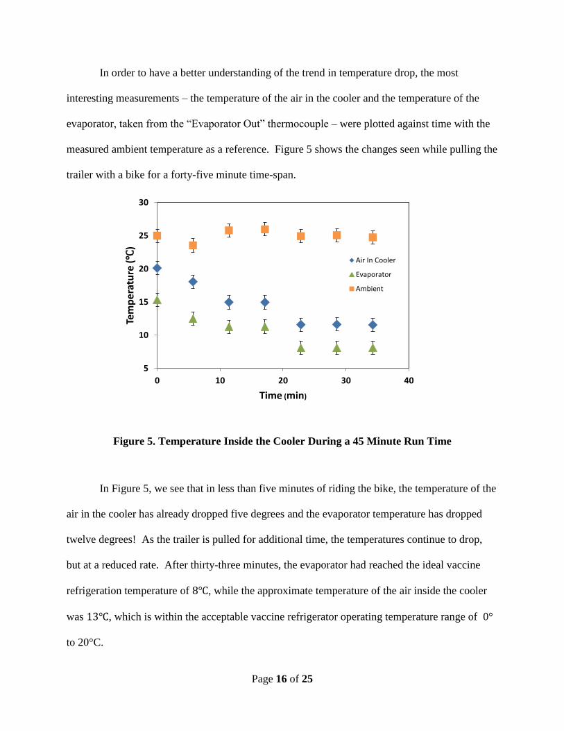
In order to have a better understanding of the trend in temperature drop, the most
interesting measurements – the temperature of the air in the cooler and the temperature of the
evaporator, taken from the “Evaporator Out” thermocouple – were plotted against time with the
measured ambient temperature as a reference. Figure 5 shows the changes seen while pulling the
trailer with a bike for a forty-five minute time-span.
Figure 5. Temperature Inside the Cooler During a 45 Minute Run Time
In Figure 5, we see that in less than five minutes of riding the bike, the temperature of the
air in the cooler has already dropped five degrees and the evaporator temperature has dropped
twelve degrees! As the trailer is pulled for additional time, the temperatures continue to drop,
but at a reduced rate. After thirty-three minutes, the evaporator had reached the ideal vaccine
refrigeration temperature of , while the approximate temperature of the air inside the cooler
was , which is within the acceptable vaccine refrigerator operating temperature range of 0°
to 20°C.
5
10
15
20
25
30
0 10 20 30 40
Tem
pe
ratu
re (
)
Time (min)
Air In Cooler
Evaporator
Ambient
Page 17 of 25
To determine how consistently the system performed, another plot was generated for a
shorter trial time of 20 minutes, but this time the trailer was pulled by hand at a slower pace than
when it was pulled behind the bike. This is seen in Figure 6. Again, it is clear that the system
begins cooling within a short period of run time. After five minutes of running, the air in the
cooler dropped six degrees and the evaporator temperature decreased nine degrees. The
temperature trends seen in Figure 6 are similar to those in Figure 5 up to the 20 minute time
span. Thus, we can assume that the system performs similarly whether the trailer is being pulled
by a bicycle or manually at a slower pace.
Figure 6. Temperatures Inside the Cooler While Trailer is Pulled By Hand
For the final test, we were interested in how the temperature within the cooler changed
while the system sat stationary after being pulled. For this trial, the trailer was pulled by hand
for ten minutes, then allowed to sit in the direct sunlight. We expected the evaporator
temperature to slowly increase and approach the temperature of the air inside the cooler. The
10
15
20
25
30
35
0 10 20 30
Tem
pe
ratu
re (
)
Time (min)
Air In Cooler
Evaporator
Ambient
Page 18 of 25
data shown in Figure 7 shows the actual data collected over the ten minute run time and the
additional twenty five minutes of “resting” time.
Figure 7. Temperatures Inside the Cooler For Ten Minutes of Running Followed by
Resting Period
The data shows that one would expect. As the trailer was pulled by hand for ten minutes,
the evaporator reached a low temperature as it was cooling the air inside the cooler. Once the
system was no longer running, the evaporator and the inner air began to approach each other.
The inner air temperature remained at for the entire measured twenty-five minutes when
the system was stationary as the evaporator reached the inner air temperature.
Conclusion
Using a vapor compression refrigeration cycle mounted on a trailer to reject thermal
energy from a conventional ice chest, we were able to provide adequate cooling for vaccine
transport. With the target temperature range between and , we found that on a day of
10
15
20
25
30
0 10 20 30 40
Tem
pe
ratu
re (
)
Time (min)
Ambient
Air In Cooler
Evaporator
Page 19 of 25
ambient temperature of , the air within the cooler reached a temperature of to in
under ten minutes of riding the bike at an average speed of 6.5 ft/s, or about 4.5 mph.
Given more time, it would be beneficial to test the performance of the system at a variety
of ambient temperatures. Also, now that the initial prototype has been created, there are many
improvements that we would suggest for a second prototype.
Improvements for Future Iterations:
1. Make it lighter!
As was previously described, we expected the compressor to be difficult to spin. To
account for the expected difficulty, we made the trailer intentionally heavy. In constructing a
second prototype, there are several ways we could reduce the weight of the system. For the
trailer platform, a thinner sheet of plywood could be used. L-beams of steel, 1x1, could be
used to prevent warping and shorter pieces of 2x4 could still be used to mount the trailer
wheels. The aluminum tubing at the front of the trailer could be eliminated entirely and
replaced with two short pieces of wood to mount the receiving hitch. Lastly, we could use a
lighter material to mount the compressor.
2. Charge with less refrigerant
Charging the system with less refrigerant will prevent the compressor from developing a
significant pressure gradient at low speeds. This will allow the rider to pull the trailer at a
higher speed and still maintain cooling capacity. Finding an optimal amount of refrigerant
may be difficult; extensive communication with Superior Auto Service would likely
streamline the process.
Page 20 of 25
An alternative to this solution would be changing the gear ratio between the
compressor pulley and trailer wheel.
3. Protective cages around heat exchangers
Though we didn’t experience any issues with the condenser or evaporator, damage to
their fins is definitely a concern. Installing stiff protective meshes around both will prevent
incidental contact from reducing their effectiveness at transferring heat. For the evaporator, a
cage would promote airflow by preventing direct contact with the cooled object.
4. More flexible hoses to connect components
The size of trailer was largely based on the condenser width and the configuration of the
hoses and tubes. Reducing either or both of these factors would make the trailer lighter and
nimbler. Without purchasing a new air conditioning system, it would be impossible to
reduce the condenser width, so installing new, more flexible hoses is the most cost effective
solution.
5. Use standardized construction materials
As described previously, a significant number of our parts were donated or unique. Thus,
the current prototype could not be repeated, much less manufactured on a large scale. For the
next prototype, we would design using parts and materials typically found at a hardware
store. Doing so will produce a design that can be replicated, though it may be more
expensive than the first prototype was.
6. Connect trailer wheels with a full-length axle
Running the compressor with a belt or chain would provide a more consistent torque on
the pulley. Were we to connect the trailer wheels with an axle, the compressor load would be
Page 21 of 25
distributed between both wheels and not produce a braking effect on just one wheel.
However, installing a common axle might require a differential. More research must be
collected before committing to such a plan.
7. Modify compressor mount to allow disengaging
A limitation of our system is that it is always engaged. Is the trailer is moving, the
compressor is spinning. This produces a noticeable braking effect and turns the compressor
into a vacuum pump when the trailer is rolled backwards. The latter issue must be dealt with
by backing the trailer slowly and only over short distances. Developing a mount that allows
the compressor to disengage would solve both of these problems.
8. Develop more elegant bike connection
The current bike hitch was developed in a short span of time so that testing could be
performed as soon as possible. More attention should be given to this component, as it
impacts turning and ease of pulling.
Page 22 of 25
Appendices
Appendix A: Uncertainty Analysis
The data exhibited in this report was measured using general use T-type thermocouples
and a National Instruments DAQ card. A LabView program was used to initiate data collection
and save the accumulated data points. All of the T-type thermocouples listed on a comparison
chart on Omega.com showed that these thermocouples have a maximum estimated uncertainty of
1 or 0.75% above or below the measured temperature value. Because 1 was the larger
uncertainty for the data, all temperature-time plots were created with error bars of +/- 1 .
While the resolution of the DAQ card can affect the uncertainty, the relative magnitude
of that uncertainty compared to the measured temperature values makes this uncertainty
negligible. Uncertainty in the time domain is not of interest, as the uncertainty is much lower
than the value that is needed to measure approximate durations.
To verify the uncertainty values listed on Omega.com, we performed a calibration test.
Most of the thermocouples that were to be used for data collection were immersed in an ice bath
for two minutes so that they would have time to reach a steady-state value. The average
temperature measured and its standard deviation was calculated for each thermocouple. These
values are listed in Table 2. For six of the seven thermocouples the average temperature was less
than 1 away from , confirming the reported uncertainty from Omega.com.
Table 2. Thermocouple Calibration in Ice Bath for 2 Minutes