A Mobile RFID-based System for Supporting Evacuation of Buildings Luca Chittaro and Daniele Nadalutti HCI Lab Dept. of Math and Computer Science University of Udine via delle Scienze, 206 33100 Udine, Italy {chittaro, daniele.nadalutti}@dimi.uniud.it Abstract. Natural and man-made disasters present the need to effi- ciently and effectively evacuate the people occupying the affected build- ings. In such situations, people are usually under stress and the use of a location-aware mobile application for giving evacuation instructions in simple and effective ways can be useful to improve users’ decision making. This paper proposes a mobile system that gives evacuation instructions by employing an interactive 3D location-aware model of the building. The main focus of the paper is on the solutions and the technologies adopted for determining user’s position into the building and for inter- actively visualizing a 3D model of the building augmented with visual evacuation instructions on mobile devices. 1 Introduction Natural and man-made disasters present the need to efficiently and effectively evacuate the people occupying the affected buildings. The occupants have to be evacuated as soon as possible (e.g., in case of fire) or immediately after the event (e.g., in case of earthquake). Considering the complexity of large buildings and the possible large number of occupants, it is often difficult to organize a quick evacuation, especially when the building is seriously damaged [1]. Moreover, peo- ple in a disaster are usually under stress and may “freeze”, leading to fatalities in otherwise survivable conditions [2]. Finally, in large public buildings like air- ports, the occupants can also be unaware of the topology of the building or the location of the emergency exits and they are usually not trained in evacuating such buildings. A location-aware mobile application for giving evacuation instructions in simple and effective ways can be useful to improve users’ decision making, pre- venting users’ errors and minimizing casualties. Moreover, location-aware mobile applications can be used for training purposes, providing the user with emer- gency simulations, so that she can learn evacuation paths for different scenarios by actually following them in the building to gain knowledge and abilities that
Transcript
A Mobile RFID-based System for SupportingEvacuation of Buildings
Abstract. Natural and man-made disasters present the need to effi-ciently and effectively evacuate the people occupying the affected build-ings. In such situations, people are usually under stress and the use ofa location-aware mobile application for giving evacuation instructions insimple and effective ways can be useful to improve users’ decision making.This paper proposes a mobile system that gives evacuation instructionsby employing an interactive 3D location-aware model of the building.The main focus of the paper is on the solutions and the technologiesadopted for determining user’s position into the building and for inter-actively visualizing a 3D model of the building augmented with visualevacuation instructions on mobile devices.
1 Introduction
Natural and man-made disasters present the need to efficiently and effectivelyevacuate the people occupying the affected buildings. The occupants have to beevacuated as soon as possible (e.g., in case of fire) or immediately after the event(e.g., in case of earthquake). Considering the complexity of large buildings andthe possible large number of occupants, it is often difficult to organize a quickevacuation, especially when the building is seriously damaged [1]. Moreover, peo-ple in a disaster are usually under stress and may “freeze”, leading to fatalitiesin otherwise survivable conditions [2]. Finally, in large public buildings like air-ports, the occupants can also be unaware of the topology of the building or thelocation of the emergency exits and they are usually not trained in evacuatingsuch buildings.
A location-aware mobile application for giving evacuation instructions insimple and effective ways can be useful to improve users’ decision making, pre-venting users’ errors and minimizing casualties. Moreover, location-aware mobileapplications can be used for training purposes, providing the user with emer-gency simulations, so that she can learn evacuation paths for different scenariosby actually following them in the building to gain knowledge and abilities that
will be useful in real emergencies. Moreover, users’ actions can be logged by theapplication for post-training analysis.
It must be noticed that distasters often cause power outages in the affectedbuilding. For this reason, the technologies (e.g., wireless networks) adopted bythe mobile application (e.g., for positioning) should not require availability ofelectrical power in the building to work properly.
This paper proposes a mobile system that uses 3D models of the buildingfor giving evacuation instructions to the user. The system employs a mobile 3Drendering engine [3] to interactively visualize a location-aware 3D model of thebuilding augmented with visual evacuation instructions. User’s position into thebuilding is determined by using active short-range RFID technology without theneed for an electrical network. The system supports also manual navigation ofthe model for training purposes or if automatic positioning is not available.
The paper is organized as follows. Section 2 will briefly discuss related work.Section 3 will describe our system, analyzing its components and motivating themajor design choices. Section 4 will provide conclusions and outline future workdirections.
2 Related Work
A location-aware mobile system to support occupants’ evacuation needs to relyon an appropriate positioning technology and to present navigation instructionsin an easy-to-understand way.
Several technologies can be employed for indoor positioning (e.g, Infrared,indoor GPS, RFID, UWB, GSM, WLAN, Bluetooth, UHF, Ultrasound). Liu etal. [4] present a survey of wireless indoor positioning systems. They compareperformance of several approaches in terms of accuracy, precision, robustness,scalability, complexity and cost.
Two well-known indoor localization systems (SpotON [5] and LANDMARC[6]) are based on active RFID technology. Both systems track the position ofa specified tag by measuring its distance from multiple RFID readers that areplaced at specific locations. The distance between a tag and a reader is com-puted based on received signal strength. To increase accuracy without placingmore RFID readers, the LANDMARC system also uses a set of RFID tags, calledreference tags, that are placed at fixed locations and serve as reference point forthe system. The position of the tracked tag is computed as the weighted averageof the positions of the k nearest reference tags, where weighting factors are basedon estimated distances between the tracked tag and the k reference tags. How-ever, these solutions for indoor localization based on RFID technology are notsuitable for mobile emergency applications because they need a network to allowthe communication between each RFID reader and a server where the positionof the tracked tag is computed. Moreover, a wireless network is also needed forsending the computed position back to the mobile device. An alternative ap-proach, less accurate but more suited to emergency situations, consists in usinga single mobile RFID reader (e.g., Compact Flash RFID reader) on the mobile
device and a set of tags that are placed at fixed locations: the mobile device canautonomously compute its position based only on distance between the readerand the tags without the need for network infrastructure.
Presentation of navigation instructions on mobile devices is a widely dis-cussed topic in the literature. Baus et al. [7] surveyed the different solutionsemployed in mobile guides, especially for tourists. Most existing solutions arebased on 2D maps, but alternative approaches have been studied, such as pho-tos of the environment augmented with visual navigation aids (e.g., arrows); 3Dmodels; textual instructions; audio directions; route sketches. Approaches basedon 2D maps have the advantage of exploiting a well-known method for repre-senting spatial information, but 3D models or augmented photos exploit naturalusers’ spatial abilities because they provide users with the same visual cues theyexploit in the real world (e.g., occlusion, size of the objects). Moreover, solutionsbased on 3D models might allow the user to train in navigating a building with-out being in it. However, using 3D graphics on mobile devices for navigationpurposes is currently a scarcely explored subject in the literature. The first in-vestigations were thought for outdoor environments [8, 9]. Later, some projectsexplored the use of 3D models for helping users in the navigation of indoor en-vironments [10]. Garcia Barbosa et al. [10] developed a framework which allowsusers to load 3D models from a remote PC server, navigate them, find an op-timal and collision-free path from one place to another, and obtain additionalinformation on objects. A significant limitation of the framework is the lack ofautomatic positioning: the user has to navigate the model manually. Moreover,the employed 3D models are very simple and this could make it difficult forusers to visually match them with the real world. Finally, the framework needsa wireless network infrastructure to compute paths.
In recent years, only a few attempts have been made at exploring the useof 3D graphics on mobile devices for presenting evacuation instructions. GarciaBarbosa et al. [10] considered the application of their framework for virtualrescue training of firefighters. Pu and Zlatanova [1] list instead the requirementsfor a mobile system and a framework to manage evacuation of buildings using3D models, but they do not implement it.
3 The proposed system
To the best of our knowledge, our system is the first mobile system that useslocation-aware 3D models of buildings for evacuation purposes. The system rep-resents paths by means of a set of bidimensional oriented arrows that are pro-jected on the floor. Emergency exits are highlighted by using spotlights [11](Figure 1).
The system uses a single compact flash RFID reader on the mobile deviceand a set of tags placed at fixed locations to determine user’s position in thebuilding and to consequently update the position and the orientation of theviewpoint in the 3D model. As it is typical of navigators, there are some limi-tations in determining user’s orientation. The system, indeed, computes user’s
Fig. 1. A 3D model augmented with evacuation instructions. Paths are represented byarrows (left figure), while landmarks are highlighted by spotlights (right figure).
orientation from her latest positions, so if the user makes a turn without signifi-cantly changing her position in the world, the system is not able to recognize thechange of orientation. Inaccurate computed orientations can lead to wrong anduseless viewpoints in the 3D model (e.g., a viewpoint that is very close to a walland orientated towards the wall), with consequent difficulties for users to matchtheir position in the real world with the 3D world. To avoid this, we adopt asolution inspired by car navigators and we snap user’s positions and orientationsto the evacuation path.
3.1 Architecture and functions
Figure 2 illustrates the architecture of the proposed system, composed by threemain modules: the Viewpoint Calculator, the Path Planner, and the MobiX3DViewer.
The Viewpoint Calculator reads the queue of detected tags from the RFIDreader, retrieves their coordinates in the real world from the Tag Positionsdatabase, and then computes the user’s current position and her orientation.Finally, it sends the corresponding position and orientation of the viewpoint inthe 3D model to the Path Planner. We use a reader for Beacon RFID tags, i.e.active tags that periodically send a signal to the reader. The specific tags we usehave a range of about 4 meters and send their signal to the reader every 500milliseconds. The RFID reader simply stores the detected tags in a queue thatis queried by the Viewpoint Calculator every 500 milliseconds.
Fig. 2. Architecture of the proposed system
The Viewpoint Calculator then computes position and orientation of theviewpoint in four steps: (i) computation of a rough viewpoint position (i.e., aposition derived by triangulating the detected RFID tags), (ii) computation ofcurrent viewpoint position by filtering the latest rough viewpoint positions, (iii)computation of rough viewpoint orientation from the latest two current view-point positions, (iv) computation of current viewpoint orientation by filteringthe latest rough viewpoint orientations.
In the first step, the Viewpoint Calculator computes a rough viewpoint posi-tion by using a simple algorithm based on detected tags and on the strength oftheir signal. For each detected tag, the algorithm estimates the distance d fromthe tag based on signal strength (which decreases exponentially as one movesaway from the tag) and is computed using the following formula [12]:
d = 10(P0−P (d))
10n
where P0 is the signal strength at 1 m, P (d) is the signal strength at dis-tance d, n is a constant that determines how the signal strength decreases asthe distance increases and has to be tuned empirically. In our tests, n has betuned to the behavior of the specific tags and reader we employ (and is equal to2.4967854). However, if the signal strength associated to a tag is over a certainthreshold, which corresponds to the typical strength obtained when the reader isvery close (< 50 cm) to a tag, then we set d equal to 0.5 m. The rough viewpoint
position is computed by using triangulation. When no tags are detected, therough viewpoint position that is generated is the one computed 500 millisecondsbefore. For this reason, the computed viewpoint in the 3D model might at timessuffer from slight delays in update. In extreme cases, if no tags are detected fora minute, the system warns that the viewpoint in the 3D model could not be insync with the actual position of the user.
In the second step, the Viewpoint Calculator computes the current viewpointposition, i.e. the position sent to the Path Planner, by filtering the latest roughviewpoint positions. We currently use a simple filter that computes the mean ofthe latest 5 rough viewpoint positions. In the first 2 seconds, when less than 5rough viewpoint positions are available, the mean is computed considering theavailable rough viewpoint positions.
In the third step, the Viewpoint Calculator computes a rough viewpointorientation as the vector between the latest two viewpoint positions.
In the fourth step, the Viewpoint Calculator computes the current viewpointorientation, i.e. the orientation sent to the MobiX3D viewer, by filtering the latestrough viewpoint orientations in the same way of the positions. The ViewpointCalculator sends current viewpoint position and orientation to the Path Plannerevery 500 milliseconds.
The Path Planner has two main functions: (i) computing the evacuation pathfrom current position to the nearest emergency exit, and (ii) snapping positionand orientation of the viewpoint computed by the Viewpoint Calculator intothe current path. To compute evacuation paths, the Path Planner uses currentviewpoint position and orientation, a 2D map of the building (derived from the3D model) and the position of the emergency exits. The evacuation path isrepresented as a directed acyclic graph G where each node is associated to awaypoint and two consecutive waypoints are connected by an edge. Formally,G = (V,E), where V = {v0, . . . , vn−1}, vi = (xi, yi, zi) is a point in space, v0
is located at the current position, and vn−1 is located at the nearest emergencyexit. E is defined as follows:
E = {(vi, vj)|vi, vj ∈ V, i = {0, . . . , n− 2}, j = i + 1}
For each edge, the Path Planner sends to the MobiX3D Viewer the positionand the orientation of a navigation arrow. The position of the i-th navigationarrow is the mean of of vi and vi+1, while its orientation is the unit vectorpointing from vi towards vi+1.To snap the position and the orientation of the viewpoint to the evacuationpath, the Path Planner locates the node vj of the evacuation path nearest tothe viewpoint and sends the coordinates of vj as viewpoint position and the unitvector pointing from vj towards vj+1 as viewpoint orientation to the MobiX3DViewer.
The MobiX3D Viewer displays the 3D model of the building augmented withthe evacuation arrows. It also allows the user to switch among automatic andmanual navigation modes. Automatic navigation mode updates the viewpointin the 3D model based on viewpoint positions and orientations sent by the Path
Planner. Manual navigation mode allows the user to navigate the model by press-ing the cursor keys of the mobile device. It is useful for training purposes or if noRFID tags are available. The input of the MobiX3D Viewer is the model of thebuilding, the position and the orientation of the viewpoint in the 3D world, themodel of the navigation arrows, their position and their orientation. The Mo-biX3D Viewer was originally proposed in [3] as a general X3D file viewer and waslater refined [13] with a basic view frustum culling algorithm and extended witha portal culling algorithm [14] for buildings. The portal culling extension is usedfor very large buildings, when the entire 3D model cannot be loaded in memory.To test the evacuation system, we used a model of our Department, made of50.000 triangles. The size of the source file is 4.38 MB, with 100 kB of textures,and can be loaded in memory without using the portal culling extension.
3.2 Tests on tag availability
We tested the system positioning algorithm on three different tag setups: (i) 4tags placed about 8 m away from each other in a 24 meter corridor, (ii) 4 tagsplaced on the vertices of a 4-meter square, and (iii) 9 tags placed on a 4-metersquare, following a regular 3x3 grid pattern (the 4-meter square was divided intofour 2-meters squares).
We performed a walk along the corridor at a constant speed in the first setup,and a walk into the square following random trajectories at a constant speed inthe second and the third setups. No other people were in the areas where testswere performed. The system logged the number of detected tags each time itsent a rough viewpoint position to the filter (i.e., every 500 milliseconds).
In the first setup, no tags were detected 49% of times when a rough viewpointposition was sent to the filter, 1 tag was detected 42% of times, and more than1 tag was detected 9% of times. In the second setup, no tags were detected 7%of times, 1 tag was detected 46% of times, and more than one tag was detected47% of times. Finally, in the third setup, no tags were detected 3% of times, 1tag was detected 6% of times, and more than 1 tag was detected 91% of times.
Although the percentage of tag detection in the first setup was not high,it caused only an intermittent and slight delay in viewpoint updating, and onecould easily match the current position in the real world with the position of theviewpoint in the 3D model. However, the second and the third setups guaranteeda higher refresh rate of the viewpoint, allowing for more immediate matching ofmovements in the real world with viewpoint changes.
3.3 Accuracy and precision
We preliminary measured the accuracy and the precision of our positioning algo-rithm by following the methodology described in [15]. We used the metric errordistance, i.e., the spatial distance between the real position and the positioncomputed by our positioning algorithm.
We carried out two tests. In the first one, we employed the third tag setupdescribed in Section 3.2. We randomly chose a number of positions in the square
and placed the mobile device equipped with the RFID reader at such positions.The mobile device remained in each position for 15 seconds (30 current viewpointpositions were computed) before moving to another position. The accuracy interms of mean distance error was 0.8 m, with a precision of 90% within 1.5 m.
In the second test, we employed the first tag setup described in Section 3.2.We walked along the corridor at a constant speed for a number of times and thewalking speed varied among the different walks. We measured an accuracy of 2m in terms of mean distance error, with a precision of 75% within 3 m.
3.4 Placing tags in the building
Placement of tags in the building is a crucial aspect for the accuracy of posi-tioning. An optimal placement guarantees the full coverage of the building byusing the minimum number of tags without losing accuracy. This problem isconsidered by the EasyReader visual tool [16] for placing RFID tags, antennasand interrogators. The tool provides the user with a 2D visual map of the floorsof the building and allows the user to drag and drop RFID components into the2D map and visually show the coverage. Once the user places the components ina satisfactory way, the tool automatically generates a bill of materials for deploy-ment and installation. However, that tool is aimed at designing configurations ofRFID readers placed at fixed locations and used to track the position of movingRFID tags.
Fig. 3. Screenshot of our visual tool for placing tags. Each semitransparent sphererepresents the coverage of the RFID tag.
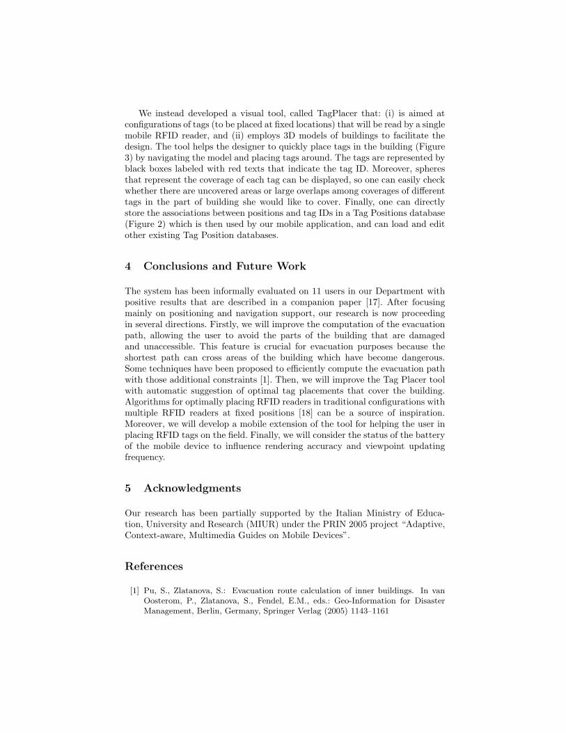
We instead developed a visual tool, called TagPlacer that: (i) is aimed atconfigurations of tags (to be placed at fixed locations) that will be read by a singlemobile RFID reader, and (ii) employs 3D models of buildings to facilitate thedesign. The tool helps the designer to quickly place tags in the building (Figure3) by navigating the model and placing tags around. The tags are represented byblack boxes labeled with red texts that indicate the tag ID. Moreover, spheresthat represent the coverage of each tag can be displayed, so one can easily checkwhether there are uncovered areas or large overlaps among coverages of differenttags in the part of building she would like to cover. Finally, one can directlystore the associations between positions and tag IDs in a Tag Positions database(Figure 2) which is then used by our mobile application, and can load and editother existing Tag Position databases.
4 Conclusions and Future Work
The system has been informally evaluated on 11 users in our Department withpositive results that are described in a companion paper [17]. After focusingmainly on positioning and navigation support, our research is now proceedingin several directions. Firstly, we will improve the computation of the evacuationpath, allowing the user to avoid the parts of the building that are damagedand unaccessible. This feature is crucial for evacuation purposes because theshortest path can cross areas of the building which have become dangerous.Some techniques have been proposed to efficiently compute the evacuation pathwith those additional constraints [1]. Then, we will improve the Tag Placer toolwith automatic suggestion of optimal tag placements that cover the building.Algorithms for optimally placing RFID readers in traditional configurations withmultiple RFID readers at fixed positions [18] can be a source of inspiration.Moreover, we will develop a mobile extension of the tool for helping the user inplacing RFID tags on the field. Finally, we will consider the status of the batteryof the mobile device to influence rendering accuracy and viewpoint updatingfrequency.
5 Acknowledgments
Our research has been partially supported by the Italian Ministry of Educa-tion, University and Research (MIUR) under the PRIN 2005 project “Adaptive,Context-aware, Multimedia Guides on Mobile Devices”.
References
[1] Pu, S., Zlatanova, S.: Evacuation route calculation of inner buildings. In vanOosterom, P., Zlatanova, S., Fendel, E.M., eds.: Geo-Information for DisasterManagement, Berlin, Germany, Springer Verlag (2005) 1143–1161
[2] Leach, J.: Why people ’freeze’ in an emergency: Temporal and cognitive con-straints on survival responses. Aviation, Space, and Environmental Medicine75(6) (2004) 539–542
[3] Nadalutti, D., Chittaro, L., Buttussi, F.: Rendering of X3D Content on MobileDevices with OpenGL ES. In: Web3D ’06: Proceedings of the eleventh interna-tional conference on 3D web technology, New York, NY, USA, ACM Press (2006)19–26
[4] Liu, H., Darabi, H., Banerjee, P., Liu, J.: Survey of wireless indoor positioningtechniques and systems. IEEE Transactions on Systems, Man, and Cybernetics,Part C: Applications and Reviews 37(6) (2007) 1067–1080
[5] Hightower, J., Want, R., Borriello, G.: SpotON: An indoor 3D location sensingtechnology based on RF signal strength. Univ. Washington, Seattle, Tech. Rep.UW CSE 2002–02–02 (2000)
[7] Baus, J., Chevers, K., Kray, C.: A survey of map-based mobile guides. In Meng, L.,Zipf, A., Reichenbacher, T., eds.: Map-based mobile services – Theories, Methodsand Implementations, Berlin, Germany, Springer Verlag (2005) 197–216
[8] Rakkolainen, I., Vainio, T.: A 3D City Info for mobile users. Computers &Graphics 25(4) (2001) 619–625
[9] Laakso, K., Gjesdal, O., Sulebak, J.: Tourist information and navigation supportby using 3D maps displayed on mobile devices. In: Proceedings of Mobile HCIWorkshop on HCI in Mobile Guides. (2003) 34–39
[10] Garcia Barbosa, R., Formico Rodrigues, M.A.: Supporting guided navigation inmobile virtual environments. In: VRST ’06: Proceedings of the ACM symposiumon Virtual reality software and technology, New York, NY, USA, ACM (2006)220–226
[11] Brusilovsky, P.: Adaptive navigation support: From adaptive hypermedia to theadaptive web and beyond. PsychNology Journal 2(1) (2004) 7–23
[12] Hallberg, J., Nilsson, M.: Positioning with Bluetooth,IrDA and RFID. LuleaUniversity of Technology, MSc. Thesis (2002)
[13] HCI Lab – University of Udine: MobiX3D website.http://hcilab.uniud.it/MobiX3D (2006)
[14] Mulloni, A., Nadalutti, D., Chittaro, L.: Interactive walkthrough of large 3dmodels of buildings on mobile devices. In: Web3D ’07: Proceedings of the twelfthinternational conference on 3D web technology, New York, NY, USA, ACM Press(2007) 17–25
[15] Xiang, Z., Song, S., Chen, J., Wang, H., Huang, J., Gao, X.: A wireless LANbased indoor positioning technology. IBM Journal of Research and Development48(5) (2004) 617–626
[17] Chittaro, L., Nadalutti, D.: Presenting evacuation instructions on mobile devicesby means of location-aware 3d virtual environments. In: MobileHCI ’08: Proceed-ings of the 10th conference on Human-computer interaction with mobile devicesand services, New York, NY, USA, ACM Press (2008)
[18] Wang, L., Norman, B., Rajgopal, J.: Placement of multiple RFID reader antennasto maximise portal read accuracy. International Journal of Radio FrequencyIdentification Technology and Applications 1(3) (2007) 260–277