A model to obtain optimal designs of railway overhead knuckle junctions using simulation Carlos Gomez ⇑ , Ruben Saa, Alberto Garcia, Felix Garcia-Carballeira, Jesus Carretero Computer Science and Engineering Department, University Carlos III of Madrid, Avda. Universidad 30, 28911 Leganes, Madrid, Spain article info Article history: Received 31 January 2012 Received in revised form 22 March 2012 Accepted 23 March 2012 Available online 11 May 2012 Keywords: Railway overhead junction Pantograph–catenary interaction Optimal design Simulation analysis abstract The design of overhead knuckle junctions in railway electrification is a crucial and complex problem. Non-optimal overhead knuckle junction designs cause limitations in train speed and, most important, malfunctions and breakages. Most railway companies have regula- tions for the design of overhead knuckle junctions. Those regulations have been defined by the experience, but, as far as we know, there are no computerized software tools to help with the task of designing and testing optimal solutions for overhead knuckle junctions. In this paper we present a simulator that allows to look for optimal configurations of over- head knuckle junctions. The simulator starts from a model based on the description of the problem that includes all the significant elements that may affect the design process, in order to find an optimal solution in terms of reliability and safety. The obtained design will be the more reliable to face failures, such as excessive wire and pantograph wears, wrong geometry configurations of the catenary, or electricity supply notches. The simula- tor also allows to evaluate current designs, so as to prove their possible flaws. This paper describes the simulation algorithm developed, the input data needed to define the exper- iments, and the achieved results. As the simulator requires heavy computational resources, high productivity parallel issues have been included in the implementation to exploit cur- rent multi-core processors. The validation and performance evaluations were made in the paper through the simulation of overhead knuckle junction designs over real switches. Their analysis will show the feasibility and applicability of our simulator. Ó 2012 Elsevier B.V. All rights reserved. 1. Introduction Since the mid-twentieth century, railway companies tend to deploy overhead lines as a mechanism to supply energy to electric locomotives [14,25]. The use of the catenary has significant advantages over other kinds of traction: it per- forms a higher power-to-weight ratio, it has less impact on environment, and it is safer in terms of accidental contacts of people or animals [9,15]. However, overhead line systems have a complex infrastructure and require significant cap- ital expenditure regarding the installation costs [7,10,16]. Moreover, the higher the train speed is, the more these costs increase [11]. Since design and deployment tasks of overhead lines are a complex engineering issue, many elements must be consid- ered. The route and camber of tracks, the pantograph geometry, the contact wires and messenger wires, the catenary support poles and portal frames, and the cantilevers to hold the wires, must be laid out so as to guarantee a correct electricity supply 1569-190X/$ - see front matter Ó 2012 Elsevier B.V. All rights reserved. http://dx.doi.org/10.1016/j.simpat.2012.03.010 ⇑ Corresponding author. Tel.: +34 916245952. E-mail addresses: [email protected](C. Gomez), [email protected](R. Saa), [email protected](A. Garcia), fgarcia@arcos. inf.uc3m.es (F. Garcia-Carballeira), [email protected](J. Carretero). Simulation Modelling Practice and Theory 26 (2012) 16–31 Contents lists available at SciVerse ScienceDirect Simulation Modelling Practice and Theory journal homepage: www.elsevier.com/locate/simpat
Transcript
Simulation Modelling Practice and Theory 26 (2012) 16–31
Contents lists available at SciVerse ScienceDirect
A model to obtain optimal designs of railway overhead knucklejunctions using simulation
Carlos Gomez ⇑, Ruben Saa, Alberto Garcia, Felix Garcia-Carballeira, Jesus CarreteroComputer Science and Engineering Department, University Carlos III of Madrid, Avda. Universidad 30, 28911 Leganes, Madrid, Spain
a r t i c l e i n f o a b s t r a c t
Article history:Received 31 January 2012Received in revised form 22 March 2012Accepted 23 March 2012Available online 11 May 2012
The design of overhead knuckle junctions in railway electrification is a crucial and complexproblem. Non-optimal overhead knuckle junction designs cause limitations in train speedand, most important, malfunctions and breakages. Most railway companies have regula-tions for the design of overhead knuckle junctions. Those regulations have been definedby the experience, but, as far as we know, there are no computerized software tools to helpwith the task of designing and testing optimal solutions for overhead knuckle junctions. Inthis paper we present a simulator that allows to look for optimal configurations of over-head knuckle junctions. The simulator starts from a model based on the description ofthe problem that includes all the significant elements that may affect the design process,in order to find an optimal solution in terms of reliability and safety. The obtained designwill be the more reliable to face failures, such as excessive wire and pantograph wears,wrong geometry configurations of the catenary, or electricity supply notches. The simula-tor also allows to evaluate current designs, so as to prove their possible flaws. This paperdescribes the simulation algorithm developed, the input data needed to define the exper-iments, and the achieved results. As the simulator requires heavy computational resources,high productivity parallel issues have been included in the implementation to exploit cur-rent multi-core processors. The validation and performance evaluations were made in thepaper through the simulation of overhead knuckle junction designs over real switches.Their analysis will show the feasibility and applicability of our simulator.
� 2012 Elsevier B.V. All rights reserved.
1. Introduction
Since the mid-twentieth century, railway companies tend to deploy overhead lines as a mechanism to supply energyto electric locomotives [14,25]. The use of the catenary has significant advantages over other kinds of traction: it per-forms a higher power-to-weight ratio, it has less impact on environment, and it is safer in terms of accidental contactsof people or animals [9,15]. However, overhead line systems have a complex infrastructure and require significant cap-ital expenditure regarding the installation costs [7,10,16]. Moreover, the higher the train speed is, the more these costsincrease [11].
Since design and deployment tasks of overhead lines are a complex engineering issue, many elements must be consid-ered. The route and camber of tracks, the pantograph geometry, the contact wires and messenger wires, the catenary supportpoles and portal frames, and the cantilevers to hold the wires, must be laid out so as to guarantee a correct electricity supply
Fig. 1. Examples of a switch and overhead knuckle junction systems.
C. Gomez et al. / Simulation Modelling Practice and Theory 26 (2012) 16–31 17
to the train, i.e., to ensure that the pantograph never loses contact with any contact wire. Other parameters, like wind influ-ence, or pantograph and contact wires wear, are also involved in the problem.
Switches are critical elements in railway networks [24], as they allow the trains to change their trajectory from one out-going track to another incoming track. Although the functionality of a switch does not change, there may be several kinds ofswitches with specific characteristics and geometries for different track speeds, different configurations for the straight track,etc. This heterogeneity results in a complex design task, since many mechanical aspects have their influence on the trackchange process. Wrong designs may lead to train derailments and hazardous breakdowns, indeed.
When considering switches on electrified tracks, the overhead knuckle junction mechanism comes into play. It allows thepantograph to lose the contact with the outgoing catenary of the straight track, and to get contact with the incoming cate-nary of the diverging track. Therefore, the pantograph has to change progressively the catenary being rubbed against, alwaysrespecting the requirement of continuous friction with the contact wire so as to avoid electricity supply notches. Overheadknuckle junctions tends to be considered a crucial issue in catenary-based railway systems. They are common points of fail-ure due to wrong designs, thus requiring a regular maintenance. Those failures have an impact on security, reliability, qualityof service, and economical costs. Fig. 1 shows real examples of overhead knuckle junction systems, that are installed overrailway switches.
The objective of this paper is to develop a simulator that allows to look for optimal configurations of overhead knucklejunctions. This simulator will start from a model based on the description of the problem, and will include all the significantelements that may affect the design process, in order to find an optimal solution in terms of reliability and safety. The ob-tained design will be the more reliable to face failures, such as excessive wire and pantograph wears, wrong geometry con-figurations of the catenary, or electricity supply notches. The simulator will also allow to evaluate current designs, so as toprove their possible flaws. This paper describes the simulation algorithm developed, the input data needed to define theexperiments, and the achieved results. In addition, we detail high productivity issues that are included in the implementa-tion to exploit current multi-core processors. The applicability and computational efficiency of the simulator is were made inthe paper through the simulation of overhead knuckle junction designs over real switches. Thus, the optimal design found, aswell as the time invested by the simulator, are presented.
This paper is structured as follows. Section 2 describes some related works in the railway simulation domain. Section 3analyzes in detail the railway overhead knuckle junction problem. Section 4 presents the simulator architecture, includinginput and output data, and also describes how the simulator manages the search for the optimal design. Section 5 shows theevaluation of the simulator by using some real overhead knuckle junction designs, in terms of both applicability and com-putational efficiency. Finally, Section 6 includes our conclusions and future works.
2. Related works
The use of simulation tools in order to help to resolve engineering problems is widely spread [22]. Railway domain is notan exception to this rule, as many research works have been carried out to improve the reliability and the quality of serviceof railway systems. Simulation has been applied in multiple areas of railway domain, like energy, planning, mechanics, etc.Bae suggests in [3] the use of simulation as an effective means to optimize the location of electric installations. Banerjee pro-poses in [5] a bond graph model to study both the stability and the curving behavior of a railway truck. Yalçinkaya shows in[28] a simulation framework to calculate a feasible timetable for a set of trains.
One of the operations demanding more accuracy in railway networks is the change of trajectory occurring along a switch,where a train runs from one track to another one. Hence, railway switches are critical points, thus requiring a special atten-
18 C. Gomez et al. / Simulation Modelling Practice and Theory 26 (2012) 16–31
tion during design, building, and maintenance stages. Carretero develops in [8] a study case to apply reliability centeredmaintenance (RCM) in large systems, underlining the importance and the impact of railway switches. The transition oper-ation so that the train changes the traveling-along track is very complex. Besides, when dealing with electric railway sys-tems, the use of catenaries and the necessity of maintaining an uniform rubbing between the pantograph and the contactwire make more difficult this track transition. Despite this challenge, research works about the pantograph–catenary inter-action at this critical point hardly have been developed.
Several separated analysis about railway switches and catenaries have been proposed, but not as an integrated prob-lem. An analysis of incipient flaws in switch machines is presented by Zatton in [29]. Nevertheless, it does not include anyother elements of railway infrastructure like overhead wires. Azevedo proposes in [2] a pantograph flaw analysis concern-ing the friction with the contact wire, but it neither copes with the geometric position of the pantograph under the wirenor covers the different rubbing conditions existing in a railway switch. Wind, a factor that may affect the position of con-tact wires, is studied by Lamb in [21], but the results are not applied to the railway domain. Keen presents in [17] differentsolutions to monitor and to detect possible flaws affecting contact wires and pantographs, but it fails to analyze overheadknuckle junctions. A mathematical model to represent the pantograph–catenary dynamic interaction is defined by Benetin [6], and a study of pantograph–catenary interaction when two catenaries overlap is made by Shimian in [26]. Thesemodels describe how the pantograph behaves in the transition from one catenary to another one in stretches belongingto the same track. The models do not cover transitions between the existing catenaries in a switch, though. This is a morecomplex task, as geometric characteristics of both catenaries are different. In [1]. Alberto implements a tool to simulatethe pantograph–catenary dynamic interaction. However, the tool does not consider the situations where the pantographchanges the catenary being rubbed against. This fact takes place in switches or in track stretches where a catenary endsand another one begins.
On the one hand, the studies concerning railway switches lack catenary issues. On the other hand, the studies related tocatenary design or pantograph–catenary interaction do not include the system behavior when the train runs along a railwayswitch. All things considered, an integrated analysis that includes all the factors affecting the overhead knuckle junction de-sign is presented in this paper.
3. The overhead knuckle junction design problem
The task of designing an overhead knuckle junction is a complex problem since several elements with differentparameters must be considered. Kitching and Holland [19] discuss the problems facing the designers of overhead equip-ment for the electrification of railways. Some research about the integration of catenaries and switches is presented in[23].
Catenary is deployed along several spans of different lengths. It is composed of a messenger wire holding a contact wirethat supplies the electric power to the pantograph of the train. Both wires are hung at a specific tension and are attached toeach other at regular intervals by drop wires. These droppers are responsible for maintaining the contact wire hung at a con-stant height with a slight deflection. Hence an uniform contact between the pantograph and the wire as the train travelsalong the track is possible, thus avoiding any notches due to the pantograph thrust force. In addition, contact wires mustbe zigzagged slightly to the left and to the right of track axis so that the pantograph wears evenly its friction surface. Thisstagger is a critical issue to be analyzed in the problem presented.
In this paper we focus on the critical study case of railway switches, where a train travelling along the straight track has tochange to the diverging track. In this situation, two different catenaries are needed to guarantee the electricity supply to bothtracks. Therefore, there will be overlapped spans along the switch stretch length. The left side of Fig. 2 shows the configu-ration of a overhead knuckle junction, where both contact wires do not cross at any point. As may be seen, the divergingtrack elevation span allows to lower the contact wire height, so that the pantograph can progressively change the rubbingwire while moving forward. The beginning of this change takes place at a characteristic point Cp, where the heights of bothelevation spans match (see the right side of Fig. 2). From this point on, the pantograph will interact with the contact wires oftwo different catenaries. Next, in the switching span, both catenaries are gradually separating. This allows the pantograph tolose the contact with the outgoing catenary and to get contact with the incoming catenary.
Fig. 2. Ground plan (left) and elevation view (right) of the configuration of a overhead knuckle junction.
C. Gomez et al. / Simulation Modelling Practice and Theory 26 (2012) 16–31 19
The point separating the two mentioned spans may be situated at any specific kilometric point along the switch, and it iscalled junction point (Jp). Its value indicates a distance from the straight track axis to the diverging track one. Since this dis-tance increases as moving forward along the switch, it is a critical design decision to choose a suitable position for the junc-tion point: the shorter the distance between the two track axis is, the nearer both catenaries are each other, and vice versa.The junction point must belong to an interval defined by railway regulations. In Spain, for non high-speed tracks, the dis-tance must be between 80 and 100 cm.
The configuration of an overhead knuckle junction poses a set of restrictions to be ensured in the simulation of the traintrajectory on the railway switch:
� When the train travels over the straight track, the pantograph should only rub the contact wire of this track. Thisavoids an excessive wear and tear of the diverging track contact wire, that may result in breakdowns and economicalcosts.� Other possible flaw points to be analyzed, may occur when the train is travelling along the diverging track. Firstly, as the
entire pantograph surface is not suitable for making contact with the contact wire, the pantograph should start rubbing itover its central part, called friction surface. Secondly, the beginning of the rub should be smooth and progressive. A haz-ardous breakdown of the catenary or the pantograph may occur otherwise. Thirdly, contact wires of both tracks must notcross, so as to avoid snagging the pantograph on the contact wire of the diverging track.� Regardless of the track to be simulated, it is essential that the pantograph is always rubbing one of the contact wires, so
that there is no electricity notches affecting the train movement.
Reliability and quality of service of railway systems will be improved by making optimal overhead knuckle junction de-signs. As a result, an economical cost reduction will also be possible. In the following sections, we propose a simulator modelin order to achieve this aim of optimal designs.
4. The proposed model
This section presents the simulation algorithm, including input and output data. By considering a set of parameters, thepantograph–catenary interaction along the switch is simulated. Thereby, an analysis of the problems that may occur in anoverhead knuckle junction is possible.
A skeleton of the main steps of the simulation algorithm is shown in Algorithm 1. As may be seen, our simulator follows a4-stage scheme in order to find an optimal solution to our overhead knuckle junction design problem:
i Definition of the problem to be simulated. This problem is typically a single switch with an overhead knucklejunction, but even with a single problem, there are many parameters to be defined, and some restrictions to beapplied according to railway regulation, physic constraint of the components, etc. All these parameters(described in Section 4.1) are stored in a simulation configuration file that is used as input for the simulationalgorithm.
ii Computation of all the possible solutions for the defined problem from the simulation configuration file data.The simulator must generate (See Algorithm 1, line 2) and process (See Algorithm 1, line 5) all the possible solutions.For each processed solution, a log file is recorded including all useful output parameters (described in Section 4.2). Theequations and algorithm proposed are described in Section 4.3. Even with the restrictions imposed in the scenario tobe simulated, the range of solutions may reach to hundreds of thousands, thus being important to optimize the exe-cution time using parallel programming techniques, as we propose in this paper.
iii Finding the set of feasible solutions. The former stage may provide two kind of solutions: feasible and unfea-sible ones. Unfeasible solutions are those that do not satisfy railway regulations, that are not able to providepower to the train in some point, or that may have some parameters out of certain limits defined by railwayexperts. In order to reduce the size of the problem so as to get an optimal solution by decreasing the executiontime, a procedure is executed to detect unfeasible solutions, thus being discarded in this step (See Algorithm 1,lines 9–16). A set of feasible solutions, that satisfies all the former constraints, is created. But even with this filter,the cardinality of this set may still range hundreds of thousands. The procedure to find an feasible solution isdescribed in detail in Section 4.4.
iv Finding and optimal solution. This step of the simulator collects all data logged for the space of feasiblesolutions, and uses them to achieve the optimal solution from a technical point of view. We define several met-rics to compare the merits of each solution and to find the optimal one. For each solution, the value of eachmetric is computed and stored into a vector. Then, a weighted equation is used to get the solution score(Algorithm 1 lines 20). The optimal solution will be the highest scored. All the process is also described in detailin Section 4.5.
20 C. Gomez et al. / Simulation Modelling Practice and Theory 26 (2012) 16–31
Input: si {switchInfrastructure}Input: ci {catenaryInfrastructure}Input: cif {catenaryInstallationFeatures}Input: sc {simulationConditions}Output: optimumDesign
{Let E the set of scenarios to be simulated}1: E ;2: E BuildSimulationScenarios(si,ci,cif,sc)
{Let S the set of possible solutions}3: S ;4: for all (ei 2 E) do5: in parallel6: S [S,simulateScenario(ei)]7: end for
{Let F the set of feasible solutions}8: F ;9: for all (si 2 S) do10: in parallel11: if isFeasible(si) then12: F [F,si]13: else14: discard(si)15: end if16: end for
{Let O the vector of optimality of the scenarios}17: O ;18: for all (fi 2 F) do19: in parallel20: O [O,computeScenarioOptimality(fi)]21: end for22: optimumDesign getOptimumDesign(O) {Gets the best scored solution}23: return optimumDesign
4.1. Input data
The simulation algorithm developed has several data inputs, that may be gathered into four groups: switch infrastructure,simulation conditions, catenary geometry, and catenary installation features. Their details are stated below.
� Switch infrastructure data (si). Data related to railway infrastructure are shown in Fig. 3, which includes the scheme of astandard railway switch. Basing on these data and trigonometry equations, the angle at any point of the switch axis can beobtained, thus allowing to simulate the pantograph position when travelling along the switch.
Fig. 3. Scheme of a standard railway switch.
C. Gomez et al. / Simulation Modelling Practice and Theory 26 (2012) 16–31 21
– a. Tangential angle of the switch.– a. Length from the switch starting point to its junction. As may be seen in Fig. 3, the switch junction is the point where
the tangential angle is applied.– r. Radius of the switch curve stretch.– b. Length from the switch junction to the ending point of its curve stretch.– d. Straight length from the ending point of the switch curve stretch to the switch ending point.– l. Total length of the switch. It is measured along the straight track from the switch starting point to the intersection
between the straight track and a line at right angles to it from the switch ending point.� Simulation conditions data (sc). In order to simulate the trajectory of the train along the railway switch, some data must be
considered so as to get a reliable approach to the reality.– Ts. Train speed.– Ws. Wind speed.– Wd. Wind direction.� Catenary infrastructure geometry data (ci). This group contains the parameters related to the modeling of the ground plan
and elevation of the catenary, i.e., its geometry. However, catenary geometry can support multiple configurations that areallowed for the given design problem. For example, one solution may be feasible whether the junction point is 90 or 120.These different configurations define the multiple solutions for the design problem. All of them must be simulated inorder to check its feasibility, i.e., whether it is a valid catenary configuration, and its optimality, i.e., whether it is the bestcatenary configuration. Therefore, several catenary parameters are defined as an interval of test values, specified by amaximum, a minimum and a delta variation. Let P an interval parameter, P ¼ fPj=Pmin 6 Pj 6 Pmax; Pj ¼ Pmin þ j � DP;
j 2 N�g. Catenary infrastructure geometry parameters are stated below, including those that are interval parameters.Fig. 2 includes a graphical view of these data.– El. Elevation span length of the catenaries of both the straight and the diverging track.– Sl. Switching span length of the catenaries of both the straight and the diverging track.– Jp = {Jpmin, Jpmax,DJp}. Junction point, where the main pole of the system is located. Its value is the distance at right
angles from the straight track to the diverging one.– Cp = {Cpmin,Cpmax,DCp}. Characteristic point where the heights of both catenaries match. It is always located at any
point of the elevation span.– e = {emin,emax,De}. Elevation of the diverging track catenary at its starting point.– h = {hmin,hmax,Dh}. Elevation of the diverging track catenary at its ending point.– s1, s2, s3; s = {smin,smax,Ds}. Staggers at the three main supporting points of the straight track catenary. Due to the cat-
enary zigzagging, s1 = s3 = �s2.– S1, S2, S3; S = {Smin,Smax,DS}. Staggers at the three main supporting points of the diverging track catenary. As men-
tioned above, S1 = S3 = �S2.– H. Height of the straight track contact wire.� Catenary installation mechanical features (cif). In addition to geometry data, it is necessary to consider some extra param-
eters in order to simulate a realistic behavior of the catenary installation features and pantograph–catenary interaction.– Kmax. Catenary stiffness at the supporting point, i.e., where the catenary is stiffer.– Kmin. Catenary stiffness in the middle of the span, where the catenary is more flexible.– Dmax. Contact wire deflection in the middle of the span. It refers to the gap under the height set for this wire.– d. Distance to the first dropper. No contact wire deflection is applied along this distance.– N. Number of contact wires belonging to the catenary. There may be one or two contact wires.– T,A. Tension and section area respectively of both the contact and the messenger wire. These parameters are respon-
sible for the behavior of the wires under wind forces.– Ccs. Type of current collection system, i.e., whether the contact wire is powered by AC or DC. It is needed to calculate
the force that the pantograph exerts on the contact wire. ETI regulation [13] is used for this aim.– epl. Effective pantograph length, i.e., the length of the pantograph friction surface, that may rub with the contact wire.
All input parameters considered, let E the set of possible solutions to be simulated, E = {e1,e2, . . . ,en}. Each element ej
belonging to E is defined as a quadrupla: ej = {si,cij,sc,cif}, where ci1, ci2, . . . , cin are all the possible combinations of catenarygeometry infrastructure data (cij) ranging the interval parameters.
4.2. Output data
In order to achieve the desired design solution, the simulator must provide the following output data for each simulationstep of a scenario i.
� ki. Kilometric point, where an iteration of the simulation algorithm has been executed.� Csi, Cdi. Output data of the catenaries belonging to the straight track and the diverging track respectively. Both, Csi and Cdi,
include the following values:
22 C. Gomez et al. / Simulation Modelling Practice and Theory 26 (2012) 16–31
– pi. Elevation applied to the contact wire by the pantograph. This is only possible when both are in contact with eachother.
– sti. Stagger of the contact wire from the pantograph asix. This stagger may take a negative or positive value, dependingon whether it is located at the left side of the pantograph axis or at the right one, respectively.
– yi. Height of the contact wire. yi already includes the elevation ei if the pantograph is rubbing this catenary.– di. Distance between the contact wire position in iteration i and its position in iteration i � 1.– bi. Angle between a horizontal line and the line joining the contact wire position in iteration i and its position in iter-
ation i � 1.� Sdi. Switching distance at this simulation kilometric point. It increases as moving forward along the switch.� Cri. Identification of the catenary being rubbed by the pantograph. Both catenaries may have contact with the pantograph
at the same time. If so, yi of both Csi and Cdi have the same values.
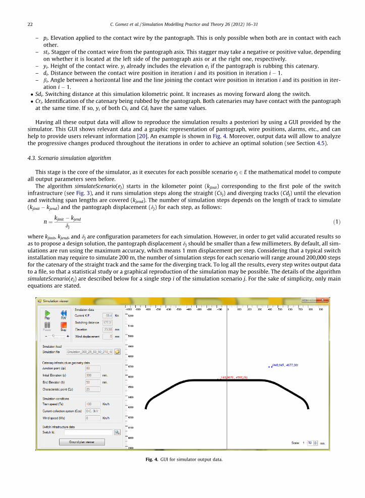
Having all these output data will allow to reproduce the simulation results a posteriori by using a GUI provided by thesimulator. This GUI shows relevant data and a graphic representation of pantograph, wire positions, alarms, etc., and canhelp to provide users relevant information [20]. An example is shown in Fig. 4. Moreover, output data will allow to analyzethe progressive changes produced throughout the iterations in order to achieve an optimal solution (see Section 4.5).
4.3. Scenario simulation algorithm
This stage is the core of the simulator, as it executes for each possible scenario ej 2 E the mathematical model to computeall output parameters seen before.
The algorithm simulateScenario(ej) starts in the kilometer point (kjinit) corresponding to the first pole of the switchinfrastructure (see Fig. 3), and it runs simulation steps along the straight (Csj) and diverging tracks (Cdj) until the elevationand switching span lengths are covered (kjend). The number of simulation steps depends on the length of track to simulate(kjinit � kjend) and the pantograph displacement (dj) for each step, as follows:
n ¼ kjinit � kjend
djð1Þ
where kjinit, kjend, and dj are configuration parameters for each simulation. However, in order to get valid accurated results soas to propose a design solution, the pantograph displacement dj should be smaller than a few millimeters. By default, all sim-ulations are run using the maximum accuracy, which means 1 mm displacement per step. Considering that a typical switchinstallation may require to simulate 200 m, the number of simulation steps for each scenario will range around 200,000 stepsfor the catenary of the straight track and the same for the diverging track. To log all the results, every step writes output datato a file, so that a statistical study or a graphical reproduction of the simulation may be possible. The details of the algorithmsimulateScenario(ej) are described below for a single step i of the simulation scenario j. For the sake of simplicity, only mainequations are stated.
Fig. 4. GUI for simulator output data.
C. Gomez et al. / Simulation Modelling Practice and Theory 26 (2012) 16–31 23
First, the pantograph position ki is computed for each simulation step i by increasing the former pantograph position inthe track with the pantograph displacement defined (see Eq. 2). For the first step, the initial position is set to the position ofthe first pole of the switch infrastructure kjinit.
ki ¼ ki�1 þ dj ð2Þ
Second step is computing contact wires position. This step is in charge of calculating the position of the contact wiresaccurately for the pantograph position at this simulation step. For the straight track, the position of the contact wire is mod-eled depending on the positions of the first and the last droppers, and the maximum deflection defined as input data. Thewire has a constant height H between the beginning of the span to the first dropper, and between the last dropper to theend of the span. However, this base value must be modified, because we must respect the deflection in the middle of thecatenary span, between the first and the last droppers. Eq. (3) is applied along the span to compute the base wire heightfor that point.
yiðkiÞ ¼H ki < d
H � deflectionðkiÞ d 6 ki < l� d
H ki P l� d
8><>: ð3Þ
where d is the distance from the beginning of the span to the first dropper, and l is El or Sl, depending on whether the currentspan is the elevation span or the switching span.
Thus, the deflection of the contact wire due to the messenger wire tension must be considered in this step. Since there aredroppers linking the messenger wire to the contact wire, the contact wire height never has a deflection larger than the limitdefined Dmax. Eq. (4) is used to compute wire deflection at each point.
deflectionðkiÞ ¼ 4 � Dmax
ðl� dÞ2
!� ððl� dÞ � ðki � dÞ � ðki � dÞ2Þ ð4Þ
Eq. (4) is derived from Eq. (5), a more general expression of wires deflection used in railway domain.
y ¼ p � x2
2 � T ð5Þ
where p is the weight per meter of the wire, T is the wire tension, and x is the distance between the calculated point and theclosest support.
Eqs. (3) and (4) are applied in every span except in the diverging track elevation span. Contact wire deflection of the latterspan is not considered, and contact wire height is obtained by applying trigonometry in the scheme of the right side of Fig. 2.
Next, we have to compute wire stagger for the wires being rubbed by the pantograph. The stagger of each contact wire sti
at this kilometric point is computed as the distance from the wire to the pantograph axis. This distance is measured at rightangles to the track axis. This parameter is also very important in order to find an optimal solution.
Fourth, we must apply environmental conditions. Depending on the simulation conditions defined by the input param-eters, wire stagger could be modified due to several environmental aspects.
Eq. (6) is used in our simulator to include the transversal wind force. The equation follows the standard EN 50119 [12] tocompute the horizontal displacement of the contact wire due to that wind in standard conditions (15� and 600 m over thesea).
Wc ¼ PvContWire þ PvMesWire ð6Þ
where
Pv ¼ qk � Gc � dWire being qk ¼12
Gq � Gt � qWs2
Gq reflects the wind burst, with a value of 2.05, as defined by the standard ENV 1991-2-4:1995 (see page 42 in [12]), Gt is aterrain factor, Ws is the wind speed, q is a factor equal to 1.225 kg/m3, and dWire is the diameter of the wire, obtained fromits section area A.
Eq. (7) is applied to calculate wire contact horizontal displacement:
wiðkiÞ ¼Wc
T
� �� k2
i
2
!ð7Þ
where Wc is the resulting wind force and T is the tension due to the catenary. The result is a quadratic curve, similar to thewire deflection.
Fifth step is determining pantograph height ei. Once calculated the contact wire positions, the pantograph height mustbe computed for this simulation step as follows. Since there are two catenaries, for the main and the diverging tracks, thepantograph height will be the minimum height of the wires that are within the projection of its friction surface, i.e., the rub-
24 C. Gomez et al. / Simulation Modelling Practice and Theory 26 (2012) 16–31
bing contact wire will be the lower one, as shown in Fig. 4. If both wires are out of the friction surface projection, then thepantograph height will be considered as 1 to indicate an error.
The result of this step allows to divide the simulation space in three areas that are very important to find an optimal de-sign solution in Section 4.5:
1. Cs pantograph interaction. All the simulation steps where the pantograph makes contact with the contact wire of thestraight track.
2. Cd pantograph interaction. All the simulation steps where the pantograph makes contact with the contact wire of thediverging track.
3. Cs ^ Cd pantograph interaction. All the simulation steps where the pantograph makes contact with both contact wires ofthe straight and the diverging track.
The sixth step is modifying contact wire elevation and angle due to the pantograph interaction. Some parametersneeded, such as elasticity in the center of the catenary spans and in the cantilevers, are received as input parameters inthe catenary installation features cif. Train speed Ts, contained in sc, has also to be considered. In order to know the elevation,the pantograph pressure over the wires must be computed, as shown in Eq. (8) that follows ETI regulation [13].
Fm ¼0:00097 � Ts2 þ 70 Ccs is A:C:0:00097 � Ts2 þ 110 Ccs is D:C: 3:0 kV0:00228 � Ts2 þ 90 Ccs is D:C: 1:5 kV
8><>: ð8Þ
Next, the elasticity is computed for the catenary point using Eq. (9), where the denominator is the stiffness at that point.This equation is detailed in [4,18,27].
EðkiÞ ¼1
K0 1� a cos 2pkil
� �� � ð9Þ
where
K0 ¼Kmax þ Kmin
2and a ¼ Kmax � Kmin
Kmax þ Kmin
The elevation of the contact wire due to the pantograph is obtained using Eq. (10).
eðkiÞ ¼ EðkiÞ � Fm ð10Þ
After determining the elevation produced by the pantograph, the definitive contact wire height must be computed as ex-pressed in Eq. (11).
yiðkiÞ ¼ yiðkiÞ þ eðkiÞ ð11Þ
Thus, the contact wire position at a kilometric point ki can be defined as the following tuple:
WpiðkiÞ ¼ ðstiðkiÞ þwiðkiÞ; yiðkiÞÞ ð12Þ
Seventh step is computing switching distance in ki. Since this distance, measured from the straight track axis to thediverging track one, increases as moving forward along the switch, its value is a crucial issue to find an optimal solution.
Last step is logging results to file. Once computed all the significant parameters, the target output data of the simulationstep are written to the simulation scenario log file. Output data were defined in Section 4.2.
4.4. Finding the set of feasible solutions
The final goal of our simulator is to propose and optimal design solution for the overhead knuckle junction design prob-lem. Currently, most railway regulations propose a junction point value of 90 to install the junction pole. As we said before,better solutions might exist in the interval (80,100), though. Thus, our simulator analyzes the results of the former simula-tions of each scenario and computes some metrics to propose an optimal solution.
However, not all the simulation scenarios executed for a single installation generate feasible solutions, as there may beconstructive errors or output data not allowed by the railway regulations. As we have to cope with hundreds of thousands ofpossible scenarios, the first operation accomplished by the simulator is to discard unfeasible solutions from all the scenariosexisting in E in order to reduce the optimization problem size. Unfeasible solutions are due to three major causes:
1. The contact wires do not interact with the pantograph. That means that pantograph height ei is set to 1 at any point ofthe scenario.
2. The stagger sti of any of the wires interacting with the pantograph is larger than the maximum stagger allowed by therailway regulations. By default, the maximum is half of the pantograph friction surface.
C. Gomez et al. / Simulation Modelling Practice and Theory 26 (2012) 16–31 25
3. Contact wires of straight and diverging tracks intersect. This fact can be deduced from the output data, as we have thecontact wire position Wpi for each wire and at every simulation step i.
Algorithm 2 shows the procedure defined to look for unfeasible solutions, isFeasible(si). This procedure is executed to ana-lyze the log file of every solution provided by the simulation of all the scenarios. After the execution of this step of the sim-ulator, unfeasible solutions are discarded and a the set of feasible solutions F is created.
Algorithm 2. Procedure isFeasible(s) to filter out unfeasible solutions
Input: s {Scenario simulation solution}Output: feasible {Boolean result indicating feasible or unfeasible solution}1: feasible TRUE2: j 03: sj 0 {Structure to log results from a step of the simulation}4: read sj from s.logfile5: while (sj – 0) ^ feasible do
2 Þ _ intersectðstraight:Wpj; diverging:WpjÞ then7: feasible FALSE8: write s and failure cause to unfeasibles.logfile9: end if10: j j + 111: read sj from s.logfile12: end while13: return feasible
4.5. Finding an optimal solution
Once the set of feasible solutions F has been created, the simulator can advance to the next phase: obtaining the optimalsolution. Thus, for each feasible scenario simulated ei 2 F, several metrics must be calculated to choose an optimal solution.However, the issue of getting such a solution for the overhead knuckle junction design problem is not defined by any reg-ulation, i.e., it is still an open research topic. We have closely cooperated with railway experts to define the metrics to beused.
According to pantograph–catenary interaction, the simulation space is divided in three zones: straight track pantograph–catenary interaction (STI), diverging track pantograph–catenary interaction (DTI), and both tracks pantograph–catenaryinteraction (BTI). BTI zone is the critical area to find the optimal solution, but the transition from the other two zones toBTI zone is also important because the contact wire must respect a certain angle when starts rubbing with the pantograph.
Algorithm 3. Procedure computeScenarioOptimality (f) to calculate optimal solution
Input: f {Scenario simulation solution (feasible)}Output: o {Solution score}1: o 02: M1 computeMetricM1(f)3: M2 computeMetricM2(f)4: M3 computeMetricM3(f)5: M4 computeMetricM4(f)6: M5 computeMetricM5(f)7: M6 computeMetricM6(f)8: o (WM1 �M1) + (WM2 �M2) + (WM3 �M3) + (WM4 �M4) + (WM5 �M5) + (WM6 �M6)9: return o
The optimal solution is the one that satisfies the following conditions:
1. Maximizing the average distance between contact wires of straight and diverging tracks, defined as metric M1. It forcesthe wires to be as far apart as possible. This will avoid potential problems due to high electrical voltages flowing throughthe wires.
26 C. Gomez et al. / Simulation Modelling Practice and Theory 26 (2012) 16–31
2. Minimizing the variance of stagger of the diverging track contact wire, defined as metric M2. This metric is intended toavoid too many sudden changes of position of the contact wire on the pantograph.
3. Minimizing the average symmetry between contact wires of straight and diverging tracks, defined as metric M3. It mea-sures the difference between the stagger of both contact wires, which are sought to be as symmetrical as possible to theaxis of the pantograph, thus avoiding a pantograph tilt towards one of the sides.
4. Minimizing the input angle of the diverging track contact wire in the pantograph along the transitions STI-BTI, defined asmetric M4. This angle is intended to be as low as possible, thus avoiding a sharp blow on the pantograph. By smoothingthe entry of the contact wire in the pantograph, damages and premature wear of the wire can be decreased.
5. Minimizing the output angle of the straight track contact wire out of the pantograph along the transitions BTI-DTI,defined as metric M5. This angle is desired to be as low as possible, thus avoiding a sharp blow on the pantograph. Thismetric is particularly important when simulating a train the other way around, i.e., from the diverging track to thestraight track.
6. Minimizing the average of stagger of the diverging track contact wire, defined as metric M6. This metric ensures that thediverging track contact wire is as focused as possible to the axis of the pantograph, thus avoiding the approximation ofthe thread to the edges of the pantograph and ensures that the contact wire is always going to enter a valid area.
Algorithm 3 shows the procedures of the simulator in charge of computing the metrics for a single feasible scenario sim-ulated ei. In the algorithm we can observe that the final value of each scenario is the sum of all the metrics. Since the values ofthe metrics are very different, they have to be normalized. As seen before, the metric M1 is maximized, but the overall func-tion, that includes all the metrics, must be minimized. To resolve this conflict, we change the sign of the M1 metric value soas to normalize the result. In order to compute the overall function, we use a specific weight to confer greater or lesserimportance on each metric.
At the end, the optimal scenario is the one that minimizes the overall function value. This algorithm is only applied to theset of feasible solutions. Since there are metrics inversely correlated, it is impossible to find a scenario having the best valueper metric, being possible to have a scenario better in some metrics and worse in other ones. According to this fact, the algo-rithm finds the best scenario considering an overall function of all metrics.
5. Experimental results
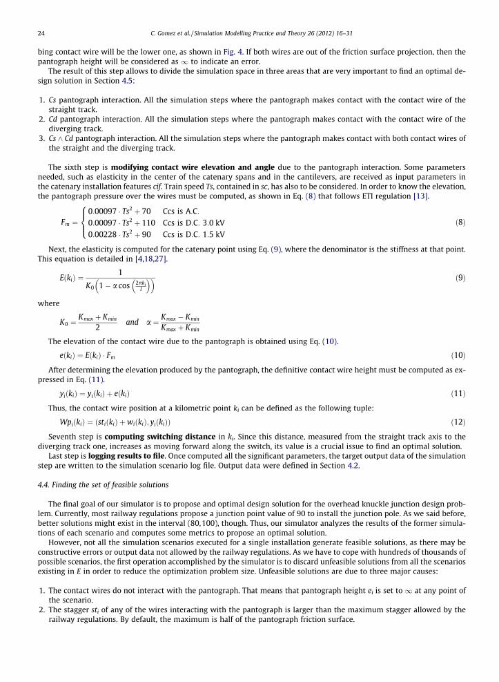
In this section we outline the experimental results obtained by running our algorithm through several study cases. Eachone of them has the input parameters presented in Table 1.
� Study cases numbered from 1 to 4, are referred to different types of non high-speed switches. On the one hand, they sharethe catenary infrastructure geometry data (ci), the catenary installation mechanical features (cif) and the simulation con-ditions data (sc). On the other hand, they differ on the switch infrastructure data (si).� Case study 5 is oriented to test our algorithm over a high-speed switch, so it has its own input parameters.
Once all the study cases have been presented, two kinds of results are desired to be studied: an analysis of the optimalscenario obtained in every study case, and a performance analysis for study case 5 in terms of computational efficiency. Byway of illustration, the former analysis will be only described in detail for study case 1. All the experiments have been carriedout simultaneously in two Linux workstations. Workstation 1 is a Intel Core i5 760 2800 MHz, 4 CPU cores, and 8 GB of RAM,and Workstation 2 is a Intel Core i7 920 2660 MHz, 8 CPU cores, and 6 GB of RAM.
5.1. Optimal switching point analysis
Table 1 shows also the values of the optimal designs obtained by the simulator for the study cases. These results haveindicated that the best value of the junction point for these non high-speed railway switches with the given catenary con-figuration, is 80. In spanish railways junction point 90 is considered to be the best value [23], though. Our research in thisarea concludes that there may be better overhead knuckle junction designs with a lower junction point value. Placing thejunction point at 80 cm, rather than 90 cm, allows to maximize the average distance between straight and diverging trackcontact wires (metric M1), thus avoiding potential problems due to electric voltages flowing through the wires.
Characteristic point Cp is another relevant outcome of these simulations. Currently, common Cp values used in Spain areabout 25, while our simulator proposes lower values. A lower Cp value reduces the input angle of the diverging track contactwire on the pantograph along the transition from one catenary to another one, mitigating the impact damage and the stressover pantograph and wires.
Fig. 5 plot the metric values and the aggregated score of a sampling set of 25 scenarios, including the optimal one, of17,500 scenarios that were generated for study case 1. These values indicates a strong correlation between metrics M1and M3, and between metrics M4 and M6. M1 and M6 metrics are inversely correlated. This suggests a trade-off betweenmaximizing the distance between wires of both tracks through increasing their staggers, and ensuring the pantograph rubsthe wire along its friction surface through decreasing the stagger of the diverging track contact wire.
0
0.5
1
1.5
2
2.5
3
3.5
4
0 5 10 15 20 25
Met
ric v
alue
Scenarios
Sampling of the solution space for the case study No. 1
C. Gomez et al. / Simulation Modelling Practice and Theory 26 (2012) 16–31 27
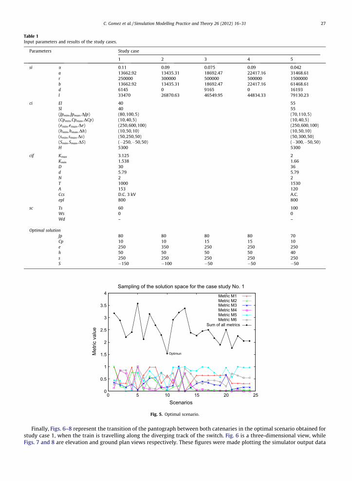
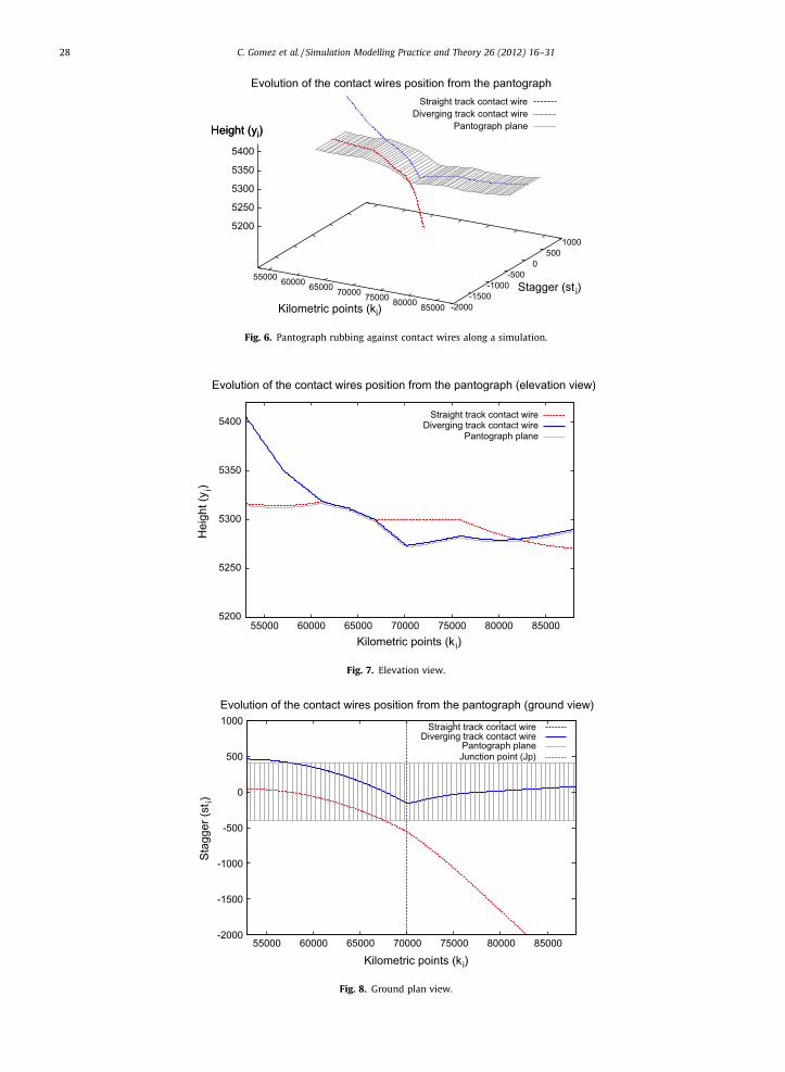
Finally, Figs. 6–8 represent the transition of the pantograph between both catenaries in the optimal scenario obtained forstudy case 1, when the train is travelling along the diverging track of the switch. Fig. 6 is a three-dimensional view, whileFigs. 7 and 8 are elevation and ground plan views respectively. These figures were made plotting the simulator output data
28 C. Gomez et al. / Simulation Modelling Practice and Theory 26 (2012) 16–31
0
200
400
600
800
1000
1200
1400
1600
1 2 4 8 12
Tim
e (s
)
Number of threads
Simulation times
Workstation1Workstation2
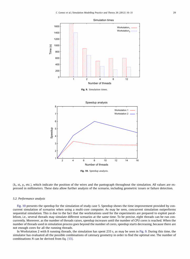
Fig. 9. Simulation times.
1
2
3
4
5
6
7
8
2 4 6 8 10 12 14 16
Spee
dup
Number of threads
Speedup analysis
Workstation 1Workstation 2
Fig. 10. Speedup analysis.
C. Gomez et al. / Simulation Modelling Practice and Theory 26 (2012) 16–31 29
(ki, sti, yi, etc.), which indicate the position of the wires and the pantograph throughout the simulation. All values are ex-pressed in millimeters. These data allow further analysis of the scenario, including geometric issues or failure detection.
5.2. Performance analysis
Fig. 10 presents the speedup for the simulation of study case 5. Speedup shows the time improvement provided by con-current simulation of scenarios when using a multi-core computer. As may be seen, concurrent simulation outperformssequential simulation. This is due to the fact that the workstations used for the experiments are prepared to exploit paral-lelism, i.e., several threads may simulate different scenarios at the same time. To be precise, eight threads can be run con-currently. Moreover, as the number of threads raises, speedup increases until the number of CPU cores is reached. When thenumber of threads used in simulation process goes beyond the number of cores, speedup starts decreasing, because there arenot enough cores for all the running threads.
In Workstation 2 with 8 running threads, the simulation has spent 233 s, as may be seen in Fig. 9. During this time, thesimulator has evaluated all the possible combinations of catenary geometry in order to find the optimal one. The number ofcombinations N can be derived from Eq. (13).
30 C. Gomez et al. / Simulation Modelling Practice and Theory 26 (2012) 16–31
N¼ Jpmax� Jpmin
DJpþ1
� �� Jpmax� Jpmin
DJpþ1
� �� Cpmax�Cpmin
DCpþ1
� �� emax�emin
Deþ1
� �� smax� smin
Dsþ1
� �� Smax�Smin
DSþ1
� �ð13Þ
Replacing the variables with the values shown in Table 1 for study case 5 results, we obtain a total amount of 45360 sce-narios evaluated.
6. Conclusions
In this paper, we have presented a simulator tool that helps railway infrastructure designers with the task of designingand calculating safer and more efficient complex overhead knuckle junctions for railway electrification systems. This task is acrucial and complex problem since non-optimal overhead knuckle junctions designs cause limitations in train speed and,most important, malfunctions and breakages. Those failures are serious because they are very expensive to be repairedand cause long traffic interruptions. The final goal of our simulator is to help designers to find and optimal solution compli-ant with the existing normative and safe from a circulation and a structural point of view. Thus, dangerous situations andspeed limitations that arise currently due to design mistakes, can be avoided. The novelty of this research is the possibilityof making automatically overhead knuckle junctions designs, choosing optimal solutions, which will enhance the systemefficiency and safety. Even when most railway companies have regulations for the design of overhead knuckle junctions,as far as we know, there are no computerized software tools to help with the task of designing and testing optimal solutions.
The simulator starts from a model based on the description of the problem that includes all the significant elements thatmay affect the design process, in order to find an optimal solution in terms of reliability and safety. The obtained design willbe the more reliable to face failures, such as excessive wire and pantograph wears, wrong geometry configurations of thecatenary, or electricity supply notches. The simulator also allows to evaluate current designs, so as to prove their possibleflaws. The simulation algorithm developed, the input data needed to define the experiments, and the achieved results aredescribed in the paper. As the simulator requires heavy computational resources, high productivity parallel issues have beenincluded in the implementation to exploit current multi-core processors. Speedup results shown in the evaluation sectionprove a significant execution time improvement and scalability provided by using parallel calculus when using multi-corecomputers. Those results are very important, as the number of cores of the computers is increasing constantly.
The feasibility and applicability of our simulator have been tested through regulations and expert judgement, being bothresults very positive. As a result, the usage of the simulator presented in this paper allows to reduce the time and effort of theoverhead knuckle junction design process, providing optimal solutions that increase the reliability of the systems. Its impactin the railway business may be important, as it may allow to railway and engineering companies to make faster and saferdesigns, avoiding also expenses due to oversized systems or to failures caused by erroneous designs. The validation and per-formance evaluations were made in the paper through the simulation of study cases based on real switches, which are in-stalled in the Spanish railways. Other input data, like catenary geometry and installation features, are also extracted fromEuropean normative and practices. Overhead knuckle junction designs obtained are in harmony with catenary characteris-tics and specifications currently in use.
The simulator is already a functional tool, but there are still many enhancements and functionalities that we would like toinclude. Using bio-inspired genetic algorithms to compute the optimal of the different metrics is our next goal. The majorchallenge here is to find a fitness function to evaluate the set of feasible solutions. Another field for future work is to providea better visualization for the results of the simulator to allow the users to study the many parameters of the solution to maketheir own elections. One shortcoming of our work is that each railway company or authority has different infrastructureinformation, catalog, and regulations. Thus, another future work would be to adapt our simulator following the Europeaninitiatives for railway interoperability. Finally, implementing the simulator as a multi-process distributed application (in-stead of a multi-core application), could enhance the system performance, allowing its execution in high-performance dis-tributed computers. By this way, the number of scenarios running concurrently may be increased several orders ofmagnitude: from 8 (common number of CPU cores in a computer) to hundreds or thousands (common number of CPU coresin a distributed supercomputer).
Acknowledgments
This work has also been partially funded by the Spanish Ministry of Science and Innovation under the Grant TIN2010-16497.
References
[1] A. Alberto, J. Benet, E. Arias, D. Cebrian, T. Rojo, F. Cuartero, A high performance tool for the simulation of the dynamic pantograph–catenaryinteraction, Mathematics and Computers in Simulation 79 (3) (2008) 652–667.
[2] C.R.F. Azevedo, A. Sinatora, Failure analysis of a railway copper contact strip, Engineering Failure Analysis 11 (6) (2004) 829–841.[3] C.H. Bae, A simulation study of installation locations and capacity of regenerative absorption inverters in DC 1500 V electric railways system,
Simulation Modelling Practice and Theory 17 (5) (2009) 829–838.
C. Gomez et al. / Simulation Modelling Practice and Theory 26 (2012) 16–31 31
[4] A. Balestrino, O. Bruno, A. Landi, L. Sani, Innovative solutions for overhead catenary–pantograph system: wire actuated control and observed contactforce, Vehicle System Dynamics 33 (2000) 69–89.
[5] N. Banerjee, A.K. Saha, R. Karmakar, R. Bhattacharyya, Bond graph modeling of a railway truck on curved track, Simulation Modelling Practice andTheory 17 (1) (2009) 22–34.
[6] J. Benet, A. Alberto, E. Arias, T. Rojo, A mathematical model of the pantograph–catenary dynamic interaction with several contact wires, InternationalJournal of Applied Mathematics 37 (2) (2007).
[7] H. Brown, Catenary design for overhead contact systems, Transactions of the American Institute of Electrical Engineers XLVI (1927) 1082–1107.[8] J. Carretero, J.M. Pérez, F. García-Carballeira, A. Calderón, J. Fernández, J.D. García, A. Lozano, L. Cardona, N. Cotaina, P. Prete, Applying RCM in large scale
systems: a case study with railway networks, Reliability Engineering & System Safety 82 (3) (2003) 257–273.[9] C.J. Clemow, Planning for railway electrification, Proceedings of the IEE 119 (4) (1972) 431–440.
[10] O.J. Crompton, G.A. Wallace, Economic aspects of overhead equipment for DC railway electrification, Proceedings of the IEE – Part I: General 100 (124)(1953) 133–145.
[11] G. De Rus, V. Inglada, Análisis coste-beneficio del tren de alta velocidad en Espana, Revista de Economía Aplicada 1 (1993) 27–48.[12] BS-EN-50119:2009. Railway Applications. Fixed Installations. Electric Traction Overhead Contact Lines, 2009.[13] ETI-C(2008) 807 Especificacion Técnica de Interoperabilidad del Subsistema de Energía del Sistema Ferroviario Transeuropeo de alta Velocidad, 2008.[14] J.W. Grieve, Electric traction. A review of progress, Proceedings of the IEE – Part A: Power Engineering 103 (9) (1956) 229–238.[15] D. Hartland, Electric contact systems – passing power to the trains, in: Electric Traction Systems, 2008 IET Professional Development Course on., 2008,
pp. 25–33.[16] J.R. Jimenez-Octavio, E. Pilo, O. Lopez-Garcia, A. Carnicero, Coupled electromechanical cost optimization of high speed railway overheads, in: ASME
Conference Proceedings, vol. 2006(42037), 2006, pp. 231–240.[17] P.M. Keen, Monitoring overhead line equipment, IEE Current Collections for High Speed Trains Seminar (1998) 3/1–3/3.[18] J.W. Kima, H.C. Chaeb, B.S. Parkc, S.Y. Leed, C.S. Hand, J.S. Jang, State sensitivity analysis of the pantograph system for a high speed rail vehicle
considering span length and static uplift force, Journal of sound and Vibration 303 (3–5) (2007) 405–427.[19] F.B. Kitchin, J. Holland, Railway electrification: design of overhead equipment, Journal of the Institution of Electrical Engineers 1950 (11) (1950) 292.[20] J. Kuljis, User interfaces and discrete event simulation models, Simulation Practice and Theory 1 (5) (1994) 207–221.[21] E.H. Lamb, The behaviour of overhead transmission lines in high winds, Journal of the Institution of Electrical Engineers 66 (382) (1928) 1079–1085.[22] F. Maceri, F. Casciati, Modelling and simulation of advanced problems and smart systems in civil engineering, Simulation Modelling Practice and
Theory 11 (5–6) (2003) 313.[23] J. Montesinos, M. Carmona, Tecnologı́a de Catenaria, ADIF, 2007.[24] M. Rodríguez, J.M. García, Desvíos Ferroviarios, RENFE, 1995.[25] B.A. Ross, A survey of Western European AC electrified railway supply substation and catenary system techniques and standards, IEEE Transactions on
Industry and General Applications IGA-7 (5) (1971) 666–672.[26] M. Shimian, Y. Fujii, The most suitable structure of contact wire on overlap sections of Shinkansen lines, Proceedings of the WCRR C (1997) 281–286.[27] T. Wu, M.J. Bernnan, Dynamic stiffness of railway overhead wire system and its effect on pantograph–catenary system dynamics, Journal of Sound and
vibration 219 (3) (1999) 483–502.[28] O. Yalçinkaya, G.M. Bayhan, A feasible timetable generator simulation modelling framework for train scheduling problem, Simulation Modelling
Practice and Theory 20 (1) (2012) 124–141.[29] E. Zattoni, Detection of incipient failures by using an H2-norm criterion: application to railway switching points, Control Engineering Practice 14 (8)