Eric S. Hendricks and Jonathan A. Seidel Glenn Research Center, Cleveland, Ohio A Multidisciplinary Approach to Mixer-Ejector Analysis and Design NASA/TM—2012-217709 September 2012 AIAA–2012–4224 https://ntrs.nasa.gov/search.jsp?R=20120014349 2018-08-30T04:14:02+00:00Z
Transcript
Eric S. Hendricks and Jonathan A. SeidelGlenn Research Center, Cleveland, Ohio
A Multidisciplinary Approach to Mixer-Ejector Analysis and Design
Since its founding, NASA has been dedicated to the advancement of aeronautics and space science. The NASA Scientific and Technical Information (STI) program plays a key part in helping NASA maintain this important role.
The NASA STI Program operates under the auspices of the Agency Chief Information Officer. It collects, organizes, provides for archiving, and disseminates NASA’s STI. The NASA STI program provides access to the NASA Aeronautics and Space Database and its public interface, the NASA Technical Reports Server, thus providing one of the largest collections of aeronautical and space science STI in the world. Results are published in both non-NASA channels and by NASA in the NASA STI Report Series, which includes the following report types: • TECHNICAL PUBLICATION. Reports of
completed research or a major significant phase of research that present the results of NASA programs and include extensive data or theoretical analysis. Includes compilations of significant scientific and technical data and information deemed to be of continuing reference value. NASA counterpart of peer-reviewed formal professional papers but has less stringent limitations on manuscript length and extent of graphic presentations.
• TECHNICAL MEMORANDUM. Scientific
and technical findings that are preliminary or of specialized interest, e.g., quick release reports, working papers, and bibliographies that contain minimal annotation. Does not contain extensive analysis.
• CONTRACTOR REPORT. Scientific and
technical findings by NASA-sponsored contractors and grantees.
• CONFERENCE PUBLICATION. Collected papers from scientific and technical conferences, symposia, seminars, or other meetings sponsored or cosponsored by NASA.
• SPECIAL PUBLICATION. Scientific,
technical, or historical information from NASA programs, projects, and missions, often concerned with subjects having substantial public interest.
• TECHNICAL TRANSLATION. English-
language translations of foreign scientific and technical material pertinent to NASA’s mission.
Specialized services also include creating custom thesauri, building customized databases, organizing and publishing research results.
For more information about the NASA STI program, see the following:
• Access the NASA STI program home page at http://www.sti.nasa.gov
• E-mail your question to [email protected] • Fax your question to the NASA STI
Information Desk at 443–757–5803 • Phone the NASA STI Information Desk at 443–757–5802 • Write to:
STI Information Desk NASA Center for AeroSpace Information 7115 Standard Drive Hanover, MD 21076–1320
Eric S. Hendricks and Jonathan A. SeidelGlenn Research Center, Cleveland, Ohio
A Multidisciplinary Approach to Mixer-Ejector Analysis and Design
NASA/TM—2012-217709
September 2012
AIAA–2012–4224
National Aeronautics andSpace Administration
Glenn Research Center Cleveland, Ohio 44135
Prepared for the48th Joint Propulsion Conference and Exhibitcosponsored by the AIAA, ASME, SAE, and ASEEAtlanta, Georgia, July 30–August 1, 2012
Acknowledgments
The work presented in this paper was supported by the Supersonics Project at NASA Glenn Research Center. Special thanks to Jeff Berton, Justin Gray and Clayton Meyers of NASA Glenn Research Center for their support and guidance in this research.
Available from
NASA Center for Aerospace Information7115 Standard DriveHanover, MD 21076–1320
National Technical Information Service5301 Shawnee Road
Alexandria, VA 22312
Available electronically at http://www.sti.nasa.gov
Trade names and trademarks are used in this report for identification only. Their usage does not constitute an official endorsement, either expressed or implied, by the National Aeronautics and
Space Administration.
This work was sponsored by the Fundamental Aeronautics Program at the NASA Glenn Research Center.
Level of Review: This material has been technically reviewed by technical management.
This report contains preliminary findings, subject to revision as analysis proceeds.
NASA/TM—2012-217709 1
A Multidisciplinary Approach to Mixer-Ejector Analysis and Design
Eric S. Hendricks and Jonathan A. Seidel National Aeronautics and Space Administration
Glenn Research Center Cleveland, Ohio 44135
Abstract The design of an engine for a civil supersonic aircraft presents a difficult multidisciplinary problem to
propulsion system engineers. There are numerous competing requirements for the engine, such as to be efficient during cruise while yet quiet enough at takeoff to meet airport noise regulations. The use of mixer-ejector nozzles presents one possible solution to this challenge. However, designing a mixer-ejector which will successfully address both of these concerns is a difficult proposition. Presented in this paper is an integrated multidisciplinary approach to the analysis and design of these systems. A process that uses several low-fidelity tools to evaluate both the performance and acoustics of mixer-ejectors nozzles is described. This process is further expanded to include system-level modeling of engines and aircraft to determine the effects on mission performance and noise near airports. The overall process is developed in the OpenMDAO framework currently being developed by NASA. From the developed process, sample results are given for a notional mixer-ejector design, thereby demonstrating the capabilities of the method.
Nomenclature
Cfg nozzle gross thrust coefficient Cfexp nozzle friction and expansion loss coefficient H vertical distance between noise source and microphone L horizontal (sideline) distance between noise source and microphone R absolute distance between noise source and microphone Rref reference distance between noise source and microphone θ polar (yaw) emission angle φ azimuthal (roll) emission angle
1.0 Introduction Propulsion design enabling a commercially successful and environmentally acceptable civil
supersonic transport represents one of the acmes of Multidisciplinary Design, Analysis and Optimization (MDAO) application in aerospace. Unlike their subsonic counterparts that always trend toward higher bypass ratio (BPR) for Mach ~0.8 cruise fuel economy and thereby enjoy the consequential benefits of lower takeoff jet noise, supersonic engines must consider the drag increases associated with higher BPR (low specific thrust) cycles when trying to achieve both acceptable cruise performance and regulated takeoff noise levels. Similarly, for subsonic aircraft, an optimum-performing inlet and nozzle designed for cruise differs little from that designed explicitly for take-off. However, the inlet and nozzle of a supersonic aircraft designed for optimum supersonic cruise performance must reconcile diverse inlet airflow demands and nozzle expansion ratios to attain successful performance across the larger Mach operating regime. Further compounding the MDAO issue for supersonics is the commercial desire for a low-sonic-boom vehicle which would enable supersonic overland flight. Such a vehicle typically requires a high fineness ratio, which equates to a low diameter-to-length for the propulsion system. This supersonics dichotomy between the “optimum” engine for take-off noise and the “optimum” engine for cruise efficiency and sonic boom thusly necessitates a compromise in acceptable fuel economy, and/or weight, to reconcile these competing trends and achieve commercial acceptability. Research sponsored by
NASA/TM—2012-217709 2
NASA’s Supersonic Project under the Fundamental Aeronautics Program is aggressively pursuing innovative tools, technologies, and concepts that address this dichotomy (Refs. 1 and 2). Mixer-ejector nozzle design with engine cycle integration is one such approach being pursued.
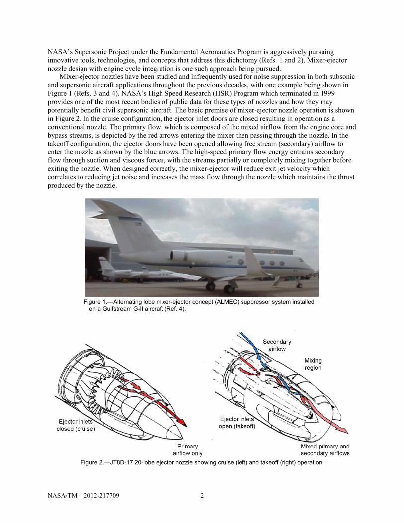
Mixer-ejector nozzles have been studied and infrequently used for noise suppression in both subsonic and supersonic aircraft applications throughout the previous decades, with one example being shown in Figure 1 (Refs. 3 and 4). NASA’s High Speed Research (HSR) Program which terminated in 1999 provides one of the most recent bodies of public data for these types of nozzles and how they may potentially benefit civil supersonic aircraft. The basic premise of mixer-ejector nozzle operation is shown in Figure 2. In the cruise configuration, the ejector inlet doors are closed resulting in operation as a conventional nozzle. The primary flow, which is composed of the mixed airflow from the engine core and bypass streams, is depicted by the red arrows entering the mixer then passing through the nozzle. In the takeoff configuration, the ejector doors have been opened allowing free stream (secondary) airflow to enter the nozzle as shown by the blue arrows. The high-speed primary flow energy entrains secondary flow through suction and viscous forces, with the streams partially or completely mixing together before exiting the nozzle. When designed correctly, the mixer-ejector will reduce exit jet velocity which correlates to reducing jet noise and increases the mass flow through the nozzle which maintains the thrust produced by the nozzle.
Figure 1.—Alternating lobe mixer-ejector concept (ALMEC) suppressor system installed
One of the attractive features of these nozzles is that the “optimum” low BPR engine cycle designed for good installed supersonic cruise performance need not be overly compromised for take-off noise abatement. The key fluid mechanics at work for secondary entrainment are the overall momentum of the primary stream entering the mixing plane, the related local static pressure of the primary stream at the primary/secondary mixing plane, and to a lesser degree, the viscous entrainment. These flow parameters, established by engine cycle selection and nozzle geometry variables govern the performance, operability, and acoustics of the system during operation. As such, MDAO techniques that combine these system-level disciplines are paramount in determining the viable design space prior to conducting more detailed design and flow analyses. In this paper, an approach to the multidisciplinary analysis of mixer-ejector nozzles at the component and aircraft system level is proposed. The multidisciplinary analysis process first evaluates the mixer-ejector nozzle as an isolated component to determine its performance and acoustic characteristics. The determined characteristics are then used as part of a system level analysis that includes evaluating the overall engine cycle, the aircraft mission performance, and the noise produced by the aircraft during takeoff and landing. Following the discussion of the development of this analysis capability, sample results are given for a notional mixer-ejector nozzle and associated aircraft to demonstrate the trades that can be studied with this new capability.
2.0 Modeling Methodology and Implementation The challenge of designing a feasible mixer-ejector nozzle is being able to understand the tradeoffs
that must occur between disciplines. For this study, an analysis process has been developed which evaluates the performance and acoustics of mixer-ejector nozzles at both a component level and a full vehicle system level. In this process, an initial engine cycle is assumed in order to provide the input flow conditions to the mixer-ejector component level analyses. Next, the mixer-ejector geometry is defined, allowing the performance characteristics of the isolated mixer-ejector nozzle to be determined. As a result of this step, a performance map which will be used in the subsequent engine cycle analysis is created and input parameters are determined for the acoustic assessment of the isolated mixer-ejector. Using these input parameters, the acoustic characteristics of the isolated nozzle are determined. The acoustic characteristics determined in this analysis will then be used as part of the system level acoustic assessment. After the performance and acoustic characteristics have been determined for the isolated mixer-ejector nozzle, the characteristics are used to evaluate the overall system-level performance and acoustic characteristics of the engine and aircraft.
In setting up this analysis process, it becomes obvious that there is a significant amount of information that needs to be passed between each of the discipline analysis tools. While this process of passing information can be done by hand for a limited number of designs, a more efficient process would be to integrate the discipline analysis tools in a multidisciplinary design, analysis and optimization (MDAO) framework. Such a framework would make executing the overall analysis process more streamlined by facilitating the passing of information and allowing complex analysis workflows to be created. There are numerous tools available for doing this type of code integration and execution. For this project, the OpenMDAO framework (Ref. 5) has been selected. OpenMDAO is an open-source, Python-based framework for solving MDAO problems. The OpenMDAO framework is currently in development, with the development process being led by NASA Glenn Research Center. This framework will serve as a key piece of the multidisciplinary analysis process described in the sections below. The following sections will describe the individual discipline analyses and how they have been incorporated into the overall MDAO process for this study.
Initial Propulsion Cycle Analyses 2.1
A Mixed Flow TurboFan (MFTF) engine cycle configuration was selected as the propulsion system for this study. The MFTF is most widely used for military supersonic propulsion systems due to its high thrust per unit airflow (specific thrust) performance, affording the most efficient airframe integration and
NASA/TM—2012-217709 4
installed supersonic cruise thrust specific fuel consumption (TSFC). At increasing supersonic speeds, inlet ram, spillage, bleed and bypass drags can severely penalize propulsion system performance. This effect is amplified as inlet pressure recovery and mass flow degrade with increasing cruise Mach number, further penalizing engine specific thrust and supersonic cruise TSFC. While the high specific thrust of a high Fan Pressure Ratio (FPR) and correspondingly low BPR MFTF helps to ameliorate this effect, a compromise in BPR and corresponding jet velocity is required to meet commercial noise certification rules for takeoff. A superior solution may be possible through the use of mixer-ejector nozzles that can improve performance and acoustic characteristics to create a better overall propulsion system.
In order to evaluate the mixer-ejector effects on a supersonic aircraft, a baseline MFTF engine cycle was modeled using information resultant from a NASA N+2 systems study contract (Ref. 6). This baseline cycle represents an aggressive technology MFTF in terms of cycle temperatures, and as such, the sea level FPR and BPR for this Mach 1.6 capable engine are 2.2 and 4.3 correspondingly. Per the contractor study report, this baseline cycle was intentionally designed to achieve a very low takeoff jet velocity while still satisfying the Mach 1.6 supersonic performance requirements, and used only a simple convergent-divergent (C-D) nozzle. An attempt was made to replace the simple nozzle for this baseline with a mixer-ejector for this current study. However, the baseline nozzle pressure ratio (NPR) for the quoted cycle conditions was so close to the critical NPR at the takeoff condition that an ejector solution with supersonic primary capable of even minimal part power operation was not possible. While a subsonic primary ejector solution is both of interest and analytically possible following the same approach outlined herein, this was deemed outside the scope of this initial study. Therefore, for purposes of this study, two alternative cycles were developed based on the same aggressive technology levels but employing higher FPRs (2.8 and 3.4) with correspondingly higher NPRs that enable the use of a mixer-ejector nozzle with supersonic primary. These two alternative, higher specific thrust cycles were scaled down in size to match the baseline cycle thrust at a rolling take-off point of Mach 0.2 sea-level, and consequently resulted in similar thrust and TSFC performance throughout the Mach envelope but with strikingly different take-off jet velocities. In total, five engine cycles were employed in this study: a NASA model of the contractor baseline MFTF with FPR=2.2 and simple C-D nozzle, NASA models of FPR=2.8 and 3.4 MFTFs with simple C-D nozzles and sized to the baseline rolling takeoff thrust, and NASA models of these same-sized FPR=2.8 and 3.4 MFTFs but utilizing mixer-ejector nozzles.
A mechanical analysis was performed for each of the five engine cycles using NASA’s Weight Analysis of Turbine Engines (WATE++) code (Ref. 7) All structural design limits based on materials selection and standard NASA design practices were observed, as were required turbine cooling flow requirements. Component efficiencies and pressure losses were based on information consistent with the contractor baseline, as were the customer bleed and horsepower extractions. A diagram of the MFTF cycle architecture is shown in Figure 3, with a sample of the corresponding mechanical flowpath design generated from WATE++.
Thermodynamic performance was computed for each cycle using the Numerical Propulsion System Simulation (NPSS) (Ref. 8) code, which included identical inlet performance characteristics. NPSS nozzle output provided input conditions to the mixer-ejector-specific analyses described in more detail in Section 2.2. The nozzle output information included primary nozzle flow conditions (total pressure, total temperature and Mach number, mass flow, areas) and downstream exit ambient conditions (static pressure). Each of these values changed as a function of the engine’s throttle setting and aircraft flight conditions, therefore these relationships needed to be included in the mixer-ejector component design/analysis process for producing the parametric nozzle performance used in subsequent cycle, mission, and acoustic analyses. Rather than integrating the entire NPSS cycle model into the mixer-ejector design/analysis process, response surface equations were created that represented primary flow conditions into the mixer-ejector nozzle. These equations were used within a module in OpenMDAO called “Cycle Parameters” to calculate requisite flow conditions input to the mixer-ejector analyses.
NASA/TM—2012-217709 5
Figure 3.—MFTF engine components (top) and a cross-section view of the engine (bottom).
Mixer-Ejector Performance Modeling 2.2
The second step in assessing the potential impact of mixer-ejector nozzles is to estimate the performance characteristics such as gross thrust coefficient and pumping ratio. The gross thrust coefficient and pumping ratio are defined in Equation (1) and Equation (2), respectively. While the performance at individual operating points is interesting, the overall goal of this analysis is to produce a performance map that covers a wide range of operating conditions. This performance map can then be used in later system level assessments to determine the overall benefit of the mixer-ejector.
𝐶𝑓𝑔 = ρ𝑢2𝐴+(𝑝−𝑝∞)�̇�𝑝𝑟𝑖𝑉ideal
(1)
Pumping Ratio = �̇�𝑠𝑒𝑐�̇�𝑝𝑟𝑖
(2)
To model the performance of mixer-ejector nozzles, an analysis tool capable of evaluating the selected design was needed. The Differential Reduced Ejector/Mixer Analysis (DREA) (Refs. 9 and 10)
NASA/TM—2012-217709 6
program was selected for this study as it provided low-fidelity results with quick execution time. DREA was developed to perform conceptual nozzle design using sophisticated flow and energy mathematics combined with an implicit 2-D space-marching numerical analysis capturing higher-order resolution. The program calculates overall performance characteristics such as secondary flow entrainment, pumping ratio, mixed jet properties, and gross thrust coefficient. In addition, the program will produce 2-D velocity profiles and mixing properties throughout the length of the ejector. Lastly, DREA is capable of handling a variety of mixer operating conditions which range from fully subsonic cases (both primary and secondary flow are subsonic) to cases where Fabri choke is encountered (the supersonic primary flow causes the secondary flow to also become supersonic in the ejector). All these features make DREA an ideal tool to estimate the performance of mixer-ejector nozzles.
In order to produce the performance maps desired for this study, a large number of DREA executions would be required to generate sufficient data. While this task could be done by inputting information from the Cycle Parameters module by hand, this process would take an extensive amount of time and be prone to human error in transferring the inputs. Therefore, the DREA code was incorporated into the OpenMDAO framework by creating a code “wrapper.” In the wrapping process, a module with functions was developed which would allow the framework to generate the required input files for DREA, execute DREA and then parse the output files to record needed data in a usable format.
The OpenMDAO DREA module and the Cycle Parameters module were then integrated into a single analysis capability to produce performance maps as shown in Figure 4. In this analysis process, a design of experiments (DoE) driver was used to execute the Cycle Parameters and DREA modules for a large number of cases. For the design of experiments, six independent variables which were considered most critical to the ejector operation were included. These independents were:
• Free stream Mach number • Flight altitude • Percent of max engine thrust which defines primary flow total pressure, total temperature and
Mach number • Delta from primary flow total pressure which was determined by the Cycle Parameters module • Delta from primary flow total temperature which was determined by the Cycle Parameters
module • Delta from primary flow Mach number which was determined by the Cycle Parameters module A number of output parameters were recorded from each case executed as part of the design of
experiments. These outputs included the gross thrust coefficient and pumping ratio which are needed for creating performance maps. The data produced using the DoE and OpenMDAO performance environment were then used to create maps by establishing the relationship between the independent parameters listed above and the output information. Regression equations in the form of second order polynomials were created for each of the performance metrics. These equations can then be imported back into the cycle analysis process to develop a system level estimate the benefit of the mixer-ejector nozzle.
Figure 4.—Performance analysis
process in OpenMDAO.
NASA/TM—2012-217709 7
Mixer-Ejector Acoustic Modeling 2.3
In addition to evaluating the performance characteristics of mixer-ejector nozzles, the acoustics characteristics need to be determined to understand the potential tradeoffs between the disciplines. For the acoustic analysis, the primary concern at the system level is determining the noise levels at each of the three certification points that are part of the airport noise metric as shown in Figure 5 (Ref. 11). This task is best performed using the Aircraft Noise Prediction Program (ANOPP). However, ANOPP does not contain a module capable of modeling the noise from a mixer-ejector. Therefore, an analysis code suitable for estimating the acoustic characteristics of mixer-ejector nozzles needed to be identified and then used to create input for ANOPP.
The HSRNoise (Ref. 12) computer program was developed during the NASA’s High Speed Research Program and is capable of estimating the acoustics of mixer-ejector nozzles. HSRNoise includes two unique noise modules for predicting mixer-ejector noise which are not available in other acoustic modeling tools. The first method, Boeing’s JN8C4 method, is an empirically-based jet noise prediction method which is based on experimental data for a number of 2-D mixer-ejector configurations. The second method, the Stone Method, is a semi-empirical correlation for 2-D mixer-ejector jet noise which was developed by Modern Technologies Corporation for GE Aircraft Engines. For the examples shown in this paper, only the Boeing JN8C4 method is used.
To execute the JN8C4 module in HSRNoise, information regarding the nozzle geometry, flow conditions and nozzle performance need to be supplied. This information is either an input to or output from the Cycle Parameters and DREA modules in OpenMDAO. (Note that DREA and HSRNoise use different formulas for calculating mixer-ejector nozzle performance requiring additional calculations to generate correct input conditions for HSRNoise). Therefore, it was logical to create an OpenMDAO module for the HSRNoise analysis code. Again, this OpenMDAO wrapper would generate the required input files for HSRNoise, execute HSRNoise and then parse the output files to record needed data.
In addition to collecting the raw data from HSRNoise, several post-processing calculations were performed in this OpenMDAO module to prepare the data to be input into ANOPP. The HSRNoise code computes acoustic data at a number of microphone locations (θ ranges from 10° to 170°) along a lateral sideline as shown in Figure 6. The location of this side line can be changed in HSRNoise by changing the parameters H and L in the figure. However, ANOPP requires the acoustic data to be on an arc (typically at a 1 ft radius) around the noise source (in this case the nozzle) rather than on a sideline. Therefore, a correction needed to be applied to the HSRNoise output in order to produce the input for ANOPP. The first part of the correction computes the distance R for each microphone along the lateral sideline using Equation (3). That distance is then used to transform the sound pressure level (SPL) values from HSRNoise to the SPL values on a 1 ft (Rref = 1 ft) lossless arc needed by ANOPP using the inverse square law as shown in Equation (4).
𝑅 = √𝐻2+𝐿2
sin(θ) (3)
𝑆𝑃𝐿1ft = 𝑆𝑃𝐿𝐻𝑆𝑅𝑁𝑜𝑖𝑠𝑒 + 20log10 �𝑅
𝑅𝑟𝑒𝑓� (4)
After correcting the HSRNoise output data for use in ANOPP, an additional component needed to be created to form the final input files for ANOPP. This OpenMDAO module creates input tables for the ANOPP’s Acoustic Data Module (ACD) which provides users the ability to input the noise of unique components that cannot be predicted by other ANOPP modules. The ACD Generator module created in OpenMDAO collects the output of several runs of HSRNoise to create the required tables for the ACD module in ANOPP.
NASA/TM—2012-217709 8
Figure 5.—Noise certification points.
Figure 6.—Geometry of acoustic analysis results.
Figure 7.—Acoustic analysis process in OpenMDAO.
Using the HSRNoise and ACD Generator modules as well as the Cycle Parameters and DREA
modules, an integrated acoustic analysis process was developed in OpenMDAO to produce the ACD tables as shown in Figure 7. This analysis process is more complicated than the previous performance analysis as it requires a general driver to execute the entire analysis as well as an analysis driver to execute a select number of cases through the Cycle Parameters, DREA and HSRNoise modules. As a result of this analysis process, ACD tables for ANOPP can be produced for each of the acoustic certification points.
NASA/TM—2012-217709 9
System Level Performance and Acoustic Assessment 2.4
The performance and acoustic modeling capabilities described in the previous two sections can be used to supply performance inputs to system level analyses to estimate the impact of using a mixer-ejector nozzle on a supersonic aircraft. The systems level analysis process consists of three separate analyses that are executed sequentially as shown in Figure 8.
First, the mixer-ejector performance maps are fed into the engine cycle analysis process. The performance maps developed for a mixer-ejector nozzle design are integrated into the final performance calculations in NPSS, while the NPSS Nozzle element is used to calculate the primary flow conditions to be used as inputs to the maps. This approach allows explicit cycle convergence using the NPSS Nozzle as either a fixed-chute mixer-ejector primary or a standard convergent-divergent nozzle, depending on whether the ejector is in operation or not. Additional calculations determining secondary mass flow from the pumping ratio correlation and its associated ram drag penalties are also included in the final performance calculations. A reference viscous and expansion loss (Cfexp) was also represented in the cycle as a function of NPR for all five cycles. This loss was assessed in addition to the gross thrust coefficient supplied by the mixer-ejector performance maps. For the MFTF cycles where a mixer-ejector was not present, a baseline Cfexp versus NPR table was utilized, with a peak Cfexp of approximately 0.987 which is consistent with the assumptions in the baseline engine. When the mixer-ejector was present but not operating, a 1 percent penalty was assumed in addition to the baseline non-mixer-ejector Cfexp. This assumption is consistent with the ejector chutes remaining in the low subsonic convergent nozzle section, mimicking a “translating throat” design whereby a dedicated throat is established fully downstream of the chutes when the ejector is not operating. When the mixer-ejector was present and operating, a reference Cfexp=0.95 was assumed. This assumption accounts for the fixed ejector chutes now acting as the nozzle throat and passing sonic and supersonic exit flow. At low NPRs (occurring during throttle operation below approximately 70 percent engine net thrust conditions), this 0.95 reference Cfexp was degraded to 0.80 to represent diffusion and separated flow within the fixed primary nozzle chute, which was otherwise allowed to overexpand to a fixed chute exit area. All these calculations and assumptions allow for the installed performance of the integrated cycle-nozzle to be determined. As a result, the cycle analysis produces engine performance throughout the possible flight envelope which will be required for completing the mission analysis.
Next, the mission analysis is conducted to evaluate the overall flight performance characteristics of a notional airplane that is using the designed engine. The mission analysis assesses the aircraft performance throughout the flight envelope and ensures the vehicle is capable of meeting all performance requirements. The baseline aircraft used in this study is a NASA representation of the low sonic-boom, small supersonic transport which resulted from the NASA N+2 systems study contract previously cited. The aircraft is capable of carrying 30 passengers at a cruise Mach number of 1.6 over a 4250 n mi distance using the baseline engine. The NASA Flight Optimization System (FLOPS) code (Ref. 13) was
Figure 8.—System level analysis process.
NASA/TM—2012-217709 10
used to perform the mission analyses. To maintain the low sonic-boom characteristics of the aircraft and consistency with quoted thrust requirements, aircraft takeoff gross weight (empty weight plus total mission fuel and payload) was held constant at 180,000 lb for all five engines in the study. Resulting mission range was used as the figure of merit for assessing changes in engine cycle performance and weight, as differences in engine weight were credited or debited to the aircraft as fuel capacity to maintaining the 180,000 lb takeoff gross weight.
Finally, the mission-sized cycle performance results and acoustic results can be used to predict a system level noise metric for the mixer-ejector nozzle. This metric is the Effective Perceived Noise Level (EPNL) at the three certification points located around the runway as shown in Figure 5. ANOPP calculates an EPNL value at each point by flying the notional aircraft along a defined flight path. To predict the noise of the aircraft, ANOPP uses a variety of modules which represent noise sources such as fan noise, core noise, jet noise and airframe noise. For this study, only the noise associated with the mixer ejector nozzle is considered and the aircraft is assumed to fly a fixed trajectory. By assuming a fixed trajectory, variations in aircraft performance that may result from using a mixer-ejector are removed from the analysis, allowing for a direct comparison to be made between mixer-ejector and conventional nozzles.
3.0 Sample Results The modeling methods and implementations described in the previous sections were used to
demonstrate the multidisciplinary analysis capabilities for a notional mixer-ejector nozzle. The mixer-ejector nozzle was selected to match with a sample MFTF engine cycle for a supersonic aircraft. The design parameters for the notional mixer-ejector nozzle are given in Table 1. The following sections describe the results for performance, acoustics and system level assessment using this configuration.
TABLE 1.—NOTIONAL MIXER-EJECTOR DESIGN PARAMETERS
Design parameter Value Primary flow area ................................................................. 12.0 ft2 Secondary flow area ............................................................. 21.0 ft2 Ejector exit area ................................................................. 31.35 ft2 Ejector aspect ratio ...................................................................... 3.0 Ejector length .......................................................................... 8.0 ft Mixer chute angles .................................................................. 10.0°
Mixer-Ejector Performance Modeling 3.1
Assuming the mixer-ejector nozzle design described above, the performance modeling process described previously was exercised. Using the DREA tool that was wrapped in OpenMDAO, a five-level full factorial design of experiments was executed. The six variables chosen for this design of experiments, along with their minimum and maximum values, are given in Table 2. This design of experiments successfully produced over 15,000 data points which were then used to develop performance maps.
TABLE 2.—DESIGN OF EXPERIMENTS VARIABLES AND RANGES
Input parameter Minimum value Maximum value Free stream Mach number 0.0 0.4 Flight altitude 0 ft 10,000 ft Percent engine thrust 60 100 Delta of primary flow total pressure from baseline –200 lbf/ft2 +200 lbf/ft2 Delta of primary flow total temperature from baseline –50 °R +50 °R Delta of primary flow Mach number from baseline –0.1 +0.1
NASA/TM—2012-217709 11
Figure 9.—Performance map correlations to input parameters.
The data produced through the design of experiments process were analyzed to produce performance
maps. Second order response surface equations were fit to the data points to produce map equations that could be used in the system level analysis. Figure 9 shows the correlation of each input variable with each of the map performance metric. Essentially, the blue line in each box shows the partial derivative for the input/output pair when all other values are assumed to be at the center of the ranges listed in Table 2. From Figure 9, it can be seen that only engine percent thrust and flight Mach have a significant effect on the gross thrust coefficient (Cfg) as the rest of the partial derivatives have slopes near zero. For the pumping ratio, the flight Mach number is clearly the most significant factor as it has the highest slope.
While the above formulation of the performance maps can be implemented in the system level analysis, it was recognized that a different but related set of input variables could be used to formulate the map making it easier to integrate in to later analyses. In this formulation, the independent variables (inputs) are directly tied to physical parameters that the cycle analysis would easily be able to determine (rather than a delta off of some baseline value set by the percent max thrust). These input variables include:
• Secondary flow total pressure • Secondary flow total temperature • Ambient static pressure • Primary flow total pressure • Primary flow total temperature • Primary flow Mach number These parameters are more commonly used in engine cycle analysis, making the developed map
easier to integrate into the system level analysis. However, extreme caution needs to be used with these equations as it is easy to unknowingly supply combinations of input parameters that are outside the range of values used to generate the equation. In this situation, the response surface equation would technically be providing an extrapolation outside of the range tested with the design of experiments. The generated response surface equations using these input parameters for gross thrust coefficient, pumping ratio and secondary mass flow are given in the Appendix.
Mixer-Ejector Acoustic Modeling 3.2
The acoustic analysis process described previously was used to produce acoustic characteristics for the notional mixer-ejector nozzle. Acoustic characteristics for the nozzle were needed specifically for the three noise certification points previously described. To generate the data for these points, the analysis process was executed for the cases described in Table 3. The flyover and approach points each required
NASA/TM—2012-217709 12
one case to be run through the analysis process. These cases assumed a flight Mach number, altitude and power setting for the notional aircraft that would use this mixer-ejector nozzle. For the lateral certification point, four cases were run again at an assumed flight condition and engine power setting. However, the azimuthal angle (φ in Figure 6) was changed for each case so that noise projected in the lateral direction could be estimated.
TABLE 3.—INPUT PARAMETERS FOR GENERATING ACOUSTIC
CHARACTERISTICS AT EACH CERTIFICATION POINT Certification
Using the cases from Table 3, Acoustic Data Module input tables were created for ANOPP by converting the data to a 1-ft, lossless arc as described in a previous section. The SPL data produced in this process varied with both emission angle and frequency as shown in Figure 10 for the sideline case at zero azimuthal angle (φ). From the figure, it can be seen that the peak SPL values occurred at an emission angle (θ) around 150° and at lower frequencies for this operating condition. Plots similar to Figure 10 can be created for other cases in Table 3; however the most important information coming from this analysis is the Acoustic Data Module inputs which will be used to assess the overall acoustic levels of the mixer-ejector nozzles in the following section.
Figure 10.—Sound pressure levels (SPL, dB) as a
function of emission angle (degrees) and frequency for the lateral case at zero azimuthal angle.
NASA/TM—2012-217709 13
System Level Performance and Acoustic Assessment 3.3
The performance maps for the mixer-ejector nozzle were integrated into the propulsion system modeling to determine the overall thrust characteristics of these two engine cycles employing these nozzles. Figure 11shows the engine TSFC as a function of the installed net thrust at two critical operating conditions for all five engine cycles: the NASA model of the contractor baseline MFTF with FPR=2.2 and simple convergent-divergent nozzle, NASA models of FPR=2.8 and 3.4 MFTFs with simple convergent-divergent nozzles and sized to the baseline rolling takeoff thrust, and NASA models of these same-sized FPR=2.8 and 3.4 MFTFs but utilizing mixer-ejector nozzles. The resulting engine airflow sizes for a rolling takeoff thrust of 41387 lbf at Mach 0.2, sea level was 732 lb/s for the MFTF FPR 3.4 cycles, 879 lb/s for the MFTF FPR 2.8 cycles, and 1140 lb/s for the baseline N+2 MFTF cycle with FPR=2.2. The higher FPR MFTF cycles enable a better rate of climb at a smaller size due to higher specific thrust with only modest cruise TSFC penalties. It must be noted that no effort was made to re-match the inlet flow lapse or re-optimize any engine design parameters of these higher FPR cycles. Even without this optimization, the higher FPR cycles exhibited only a slightly higher installed TSFC at cruise. A complete cycle optimization study would likely mitigate this modest increase in cruise TSFC. When the mixer-ejectors are added the cruise TSFC of the higher FPR cycles is further degraded, due to the loss penalty that was included for having a mixer-ejector on the engine though not operating. For this study, the mixer-ejectors where only permitted to operate below 5000 ft. altitude. At the takeoff flight condition, the mixer-ejector cycles exhibit increased thrust compared to their equally-sized non-mixer-ejector counterparts. Readily apparent in the takeoff performance of the mixer-ejector cycles in Figure 11 is the impact from the separated-flow in the fixed chutes at the lower thrust settings (below 70 percent maximum thrust). While not an issue near max throttle, a more detailed modeling effort is warranted to assure safe-operation and adequate performance at reduced power (such as for cutback), and may preclude mixer-ejector operation during very low power (such as approach; depending on low-speed aerodynamics, thrust required, and acceleration time in case of missed approach).
Figure 11.—Engine TSFC verses net thrust for sample MFTF engines with and
without mixer-ejector nozzles.
NASA/TM—2012-217709 14
Figure 12.—Aircraft range versus jet velocity for sample MFTF engines with and
without mixer-ejector nozzles. Following the development of the engine performance characteristics, the impact of the mixer-ejector
cycles was evaluated on the overall aircraft performance. Of primary interest in this study was the change to the overall range of the aircraft. In Figure 12, the range of the aircraft using each of the five cycles is plotted versus the mixed average jet velocity at the nozzle exit for max thrust operation. In this figure, it is clear that the mixer ejector nozzles reduce the jet velocity which will reduce the jet noise produced by these engine cycles. The results also show that the range of the aircraft is negatively impacted by including a mixer-ejector on the engine due to the slightly higher engine TSFC during cruise. Also, because the aircraft is assumed to have a fixed maximum takeoff gross weight in this study, the extra weight of the mixer-ejector nozzle reduces the amount of fuel that the aircraft can carry further reducing the range. However, a more complete engine and aircraft system optimization using additional variables may provide comparable range capabilities and will be the subject of future work.
Finally, the mission performance results and mixer-ejector acoustic characteristics can be combined to determine the overall system level noise metrics for the engines cycles. Figure 13 shows a comparison of the nozzle only EPNL values from only the jet noise sources at all three certification points for the higher FPR engine cycles considered in the cycle and mission analyses. For the conventional convergent-divergent nozzles, the ST2Jet noise method (Refs. 14) is used to compute the noise values. For both the FPR = 2.8 and 3.4 cycles, the engine with a mixer-ejector nozzle is more than 10 EPNdB quieter at the flyover observer and more than 15 EPNdB quieter at the sideline observer relative to the conventional nozzles. This reduction is primarily the result of lower jet velocity exiting the nozzle as displayed in Figure 12. However, at the approach observer, the mixer-ejector nozzle is slightly louder than the conventional nozzle. While the mixer-ejector nozzles show the potential to significantly reduce jet noise, it is noted that the overall EPNL levels are considerably higher than those required to meet certification requirements. While there may be several factors leading to these high EPNL values, the most likely explanation is that the JN8C4 method is not valid for the mixer-ejector operating conditions considered in this study. The JN8C4 method is empirically based and is only valid for designs that lie within the mixer-
NASA/TM—2012-217709 15
Figure 13.—Comparison of mixer-ejector nozzle and conventional nozzle acoustics for two different engine cycles.
ejector designs used to create the model. The advanced cycles used in this study may require mixer-ejector operation outside of the ranges of validity for the JN8C4 method. Absolute noise levels are currently under review along with details regarding constituent source noise modules.
4.0 Conclusion The design of an engine for a supersonic aircraft presents a difficult multidisciplinary problem to
propulsion system engineers. The engine must be capable of supplying the required thrust throughout the flight envelope while also minimizing the noise it produces during takeoff and landing. The mixer-ejector nozzle is one technology that may be able to positively impact both of these metrics by reducing takeoff jet velocities while enabling the use of smaller, higher specific thrust, higher FPR engine cycles. In order to evaluate the potential impact of mixer-ejector nozzles, a multidisciplinary analysis process has been developed and presented in this paper. The process uses low fidelity disciplinary analysis codes to predict the performance and acoustics of the isolated mixer-ejector nozzles. The results from these analysis tools are then used to estimate the overall system level performance of an aircraft and engine using these nozzles. Execution of the entire analysis process is facilitated by the use of an MDAO framework, OpenMDAO.
Using the analysis process above, a notional mixer-ejector was analyzed and applied to two different mixed flow turbofan engine cycles. The results of this study demonstrate the need for the multidisciplinary approach to evaluating the mixer-ejector nozzle as part of the overall aircraft system. The mixer-ejector nozzle provides improved thrust and fuel burn characteristics of the engine in portions of the low speed operation. However, at cruise the presence of the ejector in the non-operating condition slightly decreased the performance of the engine. As a result of this decreased performance during cruise and the higher weight of the mixer-ejector over a conventional nozzle, the range of the aircraft was negatively impacted for both higher FPR engine cycles relative to their conventional convergent-divergent nozzle counterparts. While the range of the aircraft was decreased by the presence of the mixer-
NASA/TM—2012-217709 16
ejector, the inclusion of this technology provides a significant reduction in the jet noise during takeoff. More than a 10 EPNdB reduction in jet noise is predicted at both the flyover and sideline noise certification points. These results for aircraft range and noise when using the higher FPR cycles with the mixer-ejector nozzles present an opportunity for further multidisciplinary optimization to create a better engine system compared to the baseline MFTF cycle.
The results above indicate there are potential benefits of mixer-ejector nozzles on future supersonic civil aircraft. However, it is important to note that these results are for a notional mixer-ejector design and may change in future studies as improved assumptions and analysis capabilities are included. The new mixer-ejector multidisciplinary analysis capability described in this paper presents many opportunities for future design studies. In this study, the mixer-ejector nozzle geometry was assumed fixed throughout the analysis. However, there are a number of design parameters including length, aspect ratio and primary to secondary area ratio that could be varied, resulting in a better nozzle in terms of both performance and acoustics. Furthermore, the integrated analysis process developed in this study can be used to explore the engine design trade space to find the best combination of cycle design parameters and mixer-ejector nozzle design parameters to meet the mission and acoustic requirements.
NASA/TM—2012-217709 17
Appendix The equations below are the second order response surfaces for gross thrust coefficient (Cfg),
pumping ratio and secondary mass flow that were described in Section 3.1. 𝐶𝑓𝑔 = −1.88080401145108 + 0.00251022043776385 ∗ 𝑃𝑃𝑅𝐼 − 1.22482971829852 ∗ 𝑀𝑃𝑅𝐼
References 1. Thirumurthy, D. and Jones, J., “Experimental Investigation and Computation of a Supersonic Ejector
Nozzle with Clamshells,” AIAA-2010-4725, 40th Fluid Dynamics Conference and Exhibit, 28 June-1 July 2010, Chicago, Illinois.
2. Thirumurthy, D., Blaisdell, G., Anastasios, S., and Sullivan, J., “Preliminary Design and Computational Analysis of and Ejector Nozzle with Chevrons,” AIAA-2011-918, 49th AIAA Aerospace Sciences Meeting including the New Horizons Forum and Aerospace Exposition, 4-7 January 2011, Orlando, Florida.
3. Pratt & Whitney West Palm Beach, Florida, and General Electric Aircraft Engines Cincinnati, Ohio, “Critical Propulsion Components, Volume 3: Exhaust Nozzle,” NASA/CR—2005-213584, Vol. 3, May 2005.
4. Presz, W., Reynolds, G., and Hunter, C., “Thrust Augmentation with Mixer/Ejector Systems,” AIAA-2002-0230 40th AIAA Aerospace Sciences Meeting & Exhibit, 14-17 January 2002, Reno, NV.
5. Heath, C. and Gray, J., “OpenMDAO: Framework for Flexible Multidisciplinary Design, Analysis and Optimization methods,” AIAA-2012-1673, 53rd AIAA/ASME/ASCE/AHS/ASC Structures, Structural Dynamics and Materials Conference and 20th AIAA/ASME/AHS Adaptive Structures Conference, 23-26 April 2012, Honolulu, Hawaii.
6. Welge, H.R., et al., “N+2 Supersonic Concept Development and Systems Integration,” NASA/CR—2010-216842.
7. Onat, E., and Klees, G., “A Method to Estimate Weight and Dimensions of Large and Small Gas Turbine Engines,” NASA-CR-159481, 1979.
8. Claus, R.W., Evans, A.L., Lytle, J.K., and Nichols, L.D., “Numerical Propulsion System Simulation,” Computing Systems in Engineering, Vol. 2, No. 4, pp. 357-364, 1991.
9. Dechant, L. J., “Combined Numerical/Analytical Perturbation Solutions of the Navier-Stokes Equations for Aerodynamic Ejector/Mixer Nozzle Flows,” NASA/CR—1998-207406.
10. Dechant, L. J. and Nadell, S., “A User’s Guide for the Differential Reduced Ejector/Mixer Analysis “DREA” Program: Version 1.0,” NASA/TM—1999-209073.
11. U.S. Code of Federal Regulations, Title 14, Chap. I, Part 36, Noise standards: Aircraft Type and Airworthiness Certification.
12. Rawls, J. and Yeager, J., “High Speed Research Noise Prediction Code (HSRNOISE) User’s and Theoretical Manual,” NASA/CR—2004-213014, November 2004.
13. McCullers, L.A., “Aircraft Configuration Optimization Including Optimized Flight Profiles,” Proceedings of the Symposium on Recent Experiences in Multidisciplinary Analysis and Optimization, NASA CP–2327, April 1984.
14. Stone, J.R., Krejsa, E.A., Clark, B.J., and Berton, J.J., “Jet Noise Modeling for Suppressed and Unsuppressed Aircraft in Simulated Flight,” NASA/TM—2009-215524, 2009.
REPORT DOCUMENTATION PAGE Form Approved OMB No. 0704-0188
The public reporting burden for this collection of information is estimated to average 1 hour per response, including the time for reviewing instructions, searching existing data sources, gathering and maintaining the data needed, and completing and reviewing the collection of information. Send comments regarding this burden estimate or any other aspect of this collection of information, including suggestions for reducing this burden, to Department of Defense, Washington Headquarters Services, Directorate for Information Operations and Reports (0704-0188), 1215 Jefferson Davis Highway, Suite 1204, Arlington, VA 22202-4302. Respondents should be aware that notwithstanding any other provision of law, no person shall be subject to any penalty for failing to comply with a collection of information if it does not display a currently valid OMB control number. PLEASE DO NOT RETURN YOUR FORM TO THE ABOVE ADDRESS.
1. REPORT DATE (DD-MM-YYYY) 01-09-2012
2. REPORT TYPE Technical Memorandum
3. DATES COVERED (From - To)
4. TITLE AND SUBTITLE A Multidisciplinary Approach to Mixer-Ejector Analysis and Design
5a. CONTRACT NUMBER
5b. GRANT NUMBER
5c. PROGRAM ELEMENT NUMBER
6. AUTHOR(S) Hendricks, Eric, S.; Seidel, Jonathan, A.
5d. PROJECT NUMBER
5e. TASK NUMBER
5f. WORK UNIT NUMBER WBS 984754.02.07.03.12.02
7. PERFORMING ORGANIZATION NAME(S) AND ADDRESS(ES) National Aeronautics and Space Administration John H. Glenn Research Center at Lewis Field Cleveland, Ohio 44135-3191
8. PERFORMING ORGANIZATION REPORT NUMBER E-18414
9. SPONSORING/MONITORING AGENCY NAME(S) AND ADDRESS(ES) National Aeronautics and Space Administration Washington, DC 20546-0001
10. SPONSORING/MONITOR'S ACRONYM(S) NASA
11. SPONSORING/MONITORING REPORT NUMBER NASA/TM-2012-217709
12. DISTRIBUTION/AVAILABILITY STATEMENT Unclassified-Unlimited Subject Category: 07 Available electronically at http://www.sti.nasa.gov This publication is available from the NASA Center for AeroSpace Information, 443-757-5802
13. SUPPLEMENTARY NOTES
14. ABSTRACT The design of an engine for a civil supersonic aircraft presents a difficult multidisciplinary problem to propulsion system engineers. There are numerous competing requirements for the engine, such as to be efficient during cruise while yet quiet enough at takeoff to meet airport noise regulations. The use of mixer-ejector nozzles presents one possible solution to this challenge. However, designing a mixer-ejector which will successfully address both of these concerns is a difficult proposition. Presented in this paper is an integrated multidisciplinary approach to the analysis and design of these systems. A process that uses several low-fidelity tools to evaluate both the performance and acoustics of mixer-ejectors nozzles is described. This process is further expanded to include system-level modeling of engines and aircraft to determine the effects on mission performance and noise near airports. The overall process is developed in the OpenMDAO framework currently being developed by NASA. From the developed process, sample results are given for a notional mixer-ejector design, thereby demonstrating the capabilities of the method. 15. SUBJECT TERMS Ejector; Multidisciplinary design optimization; Nozzle design; Acoustics
16. SECURITY CLASSIFICATION OF: 17. LIMITATION OF ABSTRACT UU
18. NUMBER OF PAGES
26
19a. NAME OF RESPONSIBLE PERSON STI Help Desk (email:[email protected])
a. REPORT U
b. ABSTRACT U
c. THIS PAGE U
19b. TELEPHONE NUMBER (include area code) 443-757-5802
Standard Form 298 (Rev. 8-98)Prescribed by ANSI Std. Z39-18