"A MULTILEVEL MEDIUM-VOLTAGE INVERTER FOR STEP UP TRANSFORMER-LESS GRID CONNECTION OF PHOTOVOLTAIC POWER PLANTS" UNDER THE GUIDANCE OF INTERNAL GUIDE: EXTERNAL GUIDE: MRS. ANITA I PATIL DR.H.NAGANAGOUDA ASSISTANT PROFESSOR, DIRECTOR OF NATIONAL TRAINING DEPARTMENT OF EEE,DBIT CENTRE FOR SOLAR TECHNOLOGY, KPCL Mr.VIGHNESH G VERNEKAR 1DB11EE053 Mr.SAIF ULLA BAIG 1DB11EE038 Mr.PRAHALADA.K 1DB12EE406
Transcript
"A MULTILEVEL MEDIUM-VOLTAGE INVERTER FOR STEP UP TRANSFORMER-LESS GRID CONNECTION OF PHOTOVOLTAIC POWER PLANTS"
UNDER THE GUIDANCE OF INTERNAL GUIDE: EXTERNAL GUIDE: MRS. ANITA I PATIL DR.H.NAGANAGOUDA ASSISTANT PROFESSOR, DIRECTOR OF NATIONAL TRAINING DEPARTMENT OF EEE,DBIT CENTRE FOR SOLAR TECHNOLOGY, KPCL
Mr.VIGHNESH G VERNEKAR 1DB11EE053 Mr.SAIF ULLA BAIG 1DB11EE038 Mr.PRAHALADA.K 1DB12EE406
INTRODUCTION The stability and control of grid connected PV power plants have attracted interest in recent years
A power frequency transformer operated at 50 or 60 Hz is generally used to step up the traditional inverter’s low output voltage to the medium-voltage level.
Because of the heavy weight and large size of the power frequency transformer, the PV inverter system can be expensive and complex for installation and maintenance.
As an alternative approach to achieve a compact and lightweight direct grid connection, we make use of a single- phase medium-voltage PV inverter system.
The medium-voltage inverter may be a possible solution to connect the PV power plant to the medium-voltage grid directly.
Medium-frequency link operated at a few KHz to MHz is proposed to generate multiple isolated and balanced dc sources for modular multilevel cascaded (MMC) inverters from a single source
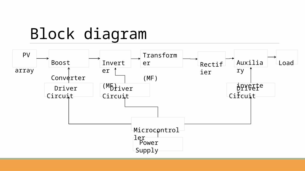
Block diagram Boost Converter
Driver Circuit
Microcontroller
Power Supply
PV array
Driver Circuit
Load Inverter (MF)
Driver Circuit
Transformer (MF)
Auxiliary inverter
Rectifier
Disadvantages
Step-up-transformer-less and line-filter-less medium-voltage grid connection,
An inherent minimization of the grid isolation problem through the magnetic link,
An inherent dc-link voltage balance due to the common magnetic link,
A wide range of MPPT operation, and
An overall compact and lightweight system.
Advantages
No of switches are more.
Photovoltaic arrayPV arrays generates power which is input to the proposed system.
PV arrays use an inverter to convert the DC power into alternating current that can power the motors, loads , lights etc.
PV cell are connected in series (for high voltage) and in parallel (for high current) to form a PV module for desired output.
The modules in the PV array are usually first connected in series to obtain the desired voltage; the individual modules are then connected in parallel to allow the system to produce more current.
Maximum Power Point TrackingMaximum power point tracking technique is used to improve the efficiency of the solar panel.
According to Maximum Power Transfer theorem, the power output of a circuit is maximum when the source impedance matches with the load impedance.
In the source side we are using a boost convertor connected to a solar panel in order to enhance the output voltage.
By changing the duty cycle of the boost converter appropriately we can match the source impedance with that of the load impedance.
Boost converterA boost converter (step-up converter) is a power converter with an output DC voltage greater than its input DC voltage.
Switches like IGBT,MOSFET are used in boost converter circuit.
Function of boost converter is to regulate, stabilize and boost the supply voltage.
Operation
In the On state, the switch S is closed, resulting in an increase in the inductor current;
In the Off state, the switch is open and the only path offered to inductor current is through the fly back diode D, the capacitor C and the load R. These results in transferring the energy accumulated during the On-state into the capacitor.
a )Switch On b )Switch Off
Microcontroller
8051 features8051 have 128 bytes of RAM ROM on 8051 is 4 Kbytes in size8051 have 128 user defined flagsIt consist of 16 bit address busIt also consist of 3 internal and 2 external interruptsLess power usage in 8051 with respect to other micro-controllerIt consist of 16-bit program counter and data pointer8051 can process 1 million one-cycle instructions per second It also consist of 32 general purpose registers each of 8 bitsIt also consist of Two 16 bit Timer/ Counter
Driver circuit
The main purpose of driver circuit is to enhance the switching voltage for the MOSFET or any switching device and also to isolate the power circuit from the microcontroller circuit.
Since the power circuit current must not enter into the microcontroller circuit, MCT2E which is the opto coupler will be connected to the buffer CD4050 which send pulse signals of 5V from microcontroller to the driver circuit.
MCT2E is the device which isolates the power circuit with the microcontroller circuit. After it gets the signal from the microcontroller it will get enhanced using the 2N2222 transistor to higher level of voltage.
After this voltage gets regulated by the use of darlington pair. The darlington is made of 2N2222 (NPN) and SK100 (PNP) transistor.
330 OHM
MCT2E
1 K22 K
100 OHM
100 OHM
100 OHM
1 K
1000 mF/25 A
G
GROUND
330 OHM
MCT2E
1 K22 K
100 OHM
100 OHM
100 OHM
1 K
1000 mF/25 A
G
GROUND
330 OHM
MCT2E
1 K22 K
100 OHM
100 OHM
100 OHM
1 K
1000 mF/25 A
G
GROUND
330 OHM
MCT2E
1 K22 K
100 OHM
100 OHM
100 OHM
1 K
1000 mF/25 A
G
GROUND
330 OHM
MCT2E
22 K
100 OHM
1 K
100 OHM
1 K
100 OHM
100 OHM
G
GROUND
100 OHM
GROUND
1000 mF/25 A
G
330 OHM
100 OHM
1000 mF/25 A
1 K
22 K
MCT2E
1 K
Multilevel inverter An inverter is a device that converts DC power into AC power at desired output voltage and frequency.
The term multilevel begins with the three levels.
The main merits of the multilevel inverter are high efficiency and good power quality.
As the number of voltage levels increases the harmonics content of the output voltage waveform decreases significantly.
Power electronic converters are operated in the “switched mode”(turn on or turn off).
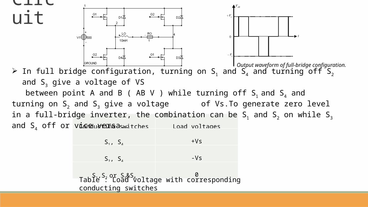
Circuit
Output waveform of full-bridge configuration.
Conducting switches Load voltages
S1, S4+Vs
S2, S4-Vs
S1,S2 or S3&S40
In full bridge configuration, turning on S1 and S4 and turning off S2 and S3 give a voltage of VS between point A and B ( AB V ) while turning off S1 and S4 and turning on S2 and S3 give a voltage
of Vs.To generate zero level in a full-bridge inverter, the combination can be S1 and S2 on while S3 and S4 off or vice versa..
Table : Load voltage with corresponding conducting switches
In transformer design, because the winding emf is proportional to the number of turns, frequency, and magnetic flux linking the winding, for a given power capacity; as the operating frequency increases, the required cross sectional area of magnetic core and the number of turns of the primary and secondary windings can be dramatically reduced.
The silicon sheet steels, which are commonly used as the core material for power frequency transformers, are not suitable for medium frequency applications because of the heavy eddy current loss.
The soft ferrites have been widely used in medium and high frequency inductors and transformers due to the low price and general availability.
This is also called inductive coil, medium frequency link, medium frequency transformer.
MAGNETIC LINK
FULL WAVE BRIDGE RECTIFIER
The Bridge rectifier is a circuit, which converts an ac voltage to dc voltage using both half cycles of the input ac voltage.
Components Driver circuit
1.IRFP460
2.Diode
1N4007
3.Capacitors
1000uF/50V
1000uF/25V
4.Optocoupler MCT2E
5.Transistors
2N2222
CK100
6.Resistors
1k
100ohm
7.Transformers
230V/12V
Boost converter1. MUR1520
2. IRFP250N
3. CAPACITOR 470uF
Inverter 1. IRFP250N
Bridge rectifier 1. BR1010
SIMULATIONSimPowerSystems-SimPowerSystems and SimMechanics of the Physical Modeling product family work together with Simulink to model electrical, mechanical and control systems.
Building the Electrical Circuit with powerlib Library
Interfacing the Electrical Circuit with Simulink
Measuring Voltages and Currents
Basic Principles of Connecting Capacitors and Inductors
Using the Powerlib Block to Simulate SimPowerSystems Models
BOOST CONVERTER CIRCUIT
BOOST OUTPUT
INVERTER CIRCUIT
INVERTER OUTPUT
PROPOSED SYSTEM 3 LEVELCIRCUIT
PROPOSED SYSTEM 3 LEVEL OUTPUT
COMPARING WITH 5 LEVEL CIRCUIT
5 LEVEL OUTPUT
FFT ANALYSIS FOR 3 LEVEL CIRCUIT
COMPARING FFT ANALYSIS FOR 5 LEVEL CIRCUIT
CONCLUSIONA new medium-voltage PV inverter system is proposed for medium or large-scale PV power plants.
A Medium frequency transformer is employed to interconnect PV arrays to form a single source.
Multiple isolated and balanced dc supplies for the multi level inverter have been generated through the common magnetic link, which automatically minimizes the voltage imbalance problem .
The grid isolation and safety problems have also been solved inherently due to electrical isolation provided by the medium-frequency link.
The elimination of the line filter and step-up transformer from the traditional system will enable large cost savings in terms of the installation, running and maintenance of the PV power plants.
Future scopePrototype voltage is limited & current is also limited that can be improved by connecting more battery banks & PV arrays.
The same concept can be used to develop the inverter for 6–36-kV system by changing the number of secondary windings and the number of levels.
Research should be carried out to fulfill the future energy demand since it is economic and renewable.
Voltage can be matched with the grid and power can be transferred from battery to grid
In the future if we are successful in generating higher power with less solar panels then this method for transmission of power from solar plant will be cost effective and maintenance free.


![Modular Cascaded H-Bridge Multilevel Photovoltaic …ijlemr.com/papers/REETA2K16/EE005.pdf · efficiency when compared to other converter topologies [17]. ... To show the necessity](https://static.documents.pub/doc/80x56/5b04bf6c7f8b9a0a548e0993/modular-cascaded-h-bridge-multilevel-photovoltaic-when-compared-to-other-converter.jpg)


