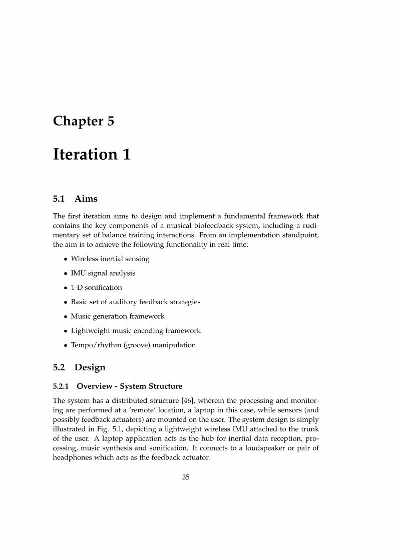
A Musical Biofeedback System for Balance and Gait Rehabilitation in Hemiparetic Stroke Patients Designing Intuitive, Relevant and Flexible Interaction Concepts for the Clinical Environment Master Thesis Prithvi Ravi Kantan Aalborg University Department of Architecture, Design and Media Technology
Transcript
A Musical Biofeedback Systemfor Balance and Gait
Rehabilitation in HemipareticStroke Patients
Designing Intuitive, Relevant and Flexible InteractionConcepts for the Clinical Environment
Master Thesis
Prithvi Ravi Kantan
Aalborg UniversityDepartment of Architecture, Design and Media Technology
This document was prepared in LaTeX using the AAU Report Template. Figures werecreated using draw.io and MATLAB.
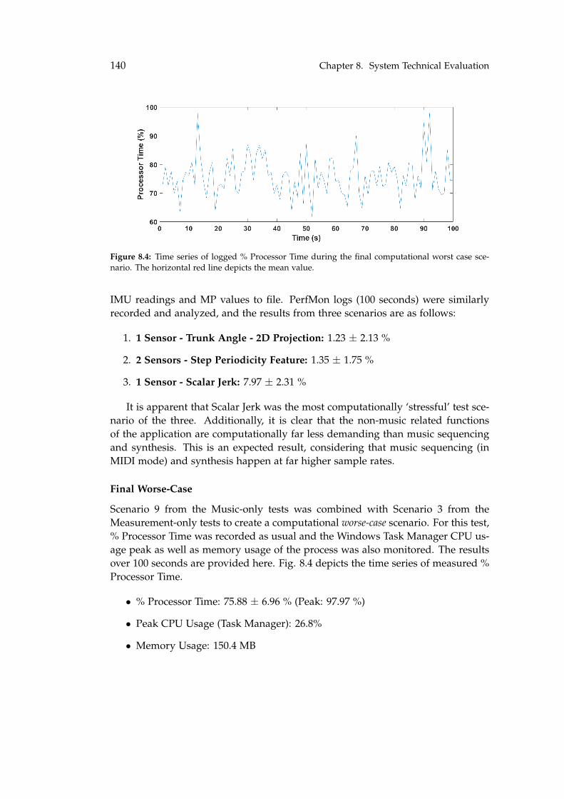
Sound and Music ComputingAalborg University
http://www.aau.dk
Title:A Musical Biofeedback System for Bal-ance and Gait Rehabilitation in Hemi-paretic Stroke Patients
Theme:Extended Master Thesis (50 ECTS)
Project Period:Autumn 2019 - Spring 2020
Project Group:Prithvi Ravi Kantan
Participant(s):Prithvi Ravi Kantan
Supervisor(s):Sofia Dahl, Erika Spaich
Copies: 1
Page Numbers: 207
Date of Completion:May 27, 2020
Abstract:
Balance and gait rehabilitation are crit-ical to the recovery of motor func-tion in hemiparetic stroke patients.Musical biofeedback has been shownto hold great rehabilitative potentialdue to its emotional appeal, capac-ity to induce and facilitate bodilymovement and documented therapeu-tic benefits. This thesis aimed to inves-tigate the types of user-tailored musi-cal biofeedback interactions and strate-gies most applicable to common reha-bilitation protocols. A prototype appli-cation based on wireless inertial sen-sors was built and iteratively evalu-ated over three development cycles incollaboration with patients and clin-icians. Results showed that the de-veloped interactions tailored to staticbalance, dynamic balance, sit-to-standand gait may be clinically useful andusable with a number of stroke patientsubgroups, promoting autonomy andaugmenting conventional training. Fu-ture studies must systematically inves-tigate short/long term physical andpsychological effects.
The content of this report is freely available, but publication (with reference) may only be pursued due to
This report was written in Spring 2020 in connection to a Master Thesis project un-dertaken over the 9th and 10th semesters of the Sound and Music Computing Msc.program at Aalborg University, Copenhagen. It was a continuation of project workfrom the previous two semesters of the program. The project was supervised byAssoc. Prof. Sofia Dahl (Department of Architecture, Design and Media Technol-ogy, AAU) as well as Assoc. Prof. Erika Spaich (Department of Health Science andTechnology, AAU). Work from two course mini-projects was integrated into theproject; The hardware component was developed as part of the Prototyping andFabrication course project, while the initial sonification strategy set was designedas part of the Research in Sound and Music Computing course project (both in the9th Semester).
This project has been a lengthy process and undergone several phases, bene-fiting from support, guidance and direction from numerous sources on its courseto completion. I would first like to thank my supervisor Sofia Dahl for her ma-jor role in this journey, which included setting up inter-department collaborationsand arrangements, regular remote supervision, sincere, consistent and exemplarypedagogy as well as psychological support at many difficult junctures over thepast year. I would also like to thank Erika Spaich for graciously agreeing to takethe time and effort to co-supervise me, helping me settle in and work comfort-ably at the HST department in Aalborg, connecting me with relevant clinicians,sharp and precise guidance on navigating the unfamiliar clinical world and build-ing a project with real-life potential. Next, I would like to thank Helle RovsingMøller Jørgensen for her irreplaceable role in testing the project with real patients,and her incredible energy and enthusiasm in planning test dates, recruiting pa-tients and conducting training sessions, all while patiently tolerating my Danish.I would then like to express my gratitude towards Peter Skotte, Jens Munk Clem-mensen, Thomas Kristensen and Markus Löchtefeld at the AAU CREATE compusfor their enthusiasm, creativity and skill in helping me build a robust hardwareprototype, as well as John Hansen and Daniel Overholt for helping with softwaretroubleshooting. I am also grateful to Naja Jensen and Laura Petrini for taking thetime to meet with me at different stages and discuss qualitative evaluation meth-
ix
x Preface
ods. Next, I would like to thank the individuals who took part in the variousstages of project evaluation, beginning with the 13 stroke patients at NeuroenhedNord, Frederikshavn who showed the incredible kindness and patience to partic-ipate in interviews and device trials. For their participation in expert interviews,I thank Daniel Skak-Mazhari Jensen (UCN Aalborg), Abhishek Srivastava, Gee-son David, Ashish Kasbe (Kokilaben Dhirubai Ambani Hospital, Mumbai), HannePallesen, Gunhild Mo Hansen (Hammel Neurocenter), Kristian Aagaard, KatarinaGuldager Skov and Mariann Borg Sømoe (Neuroenhed Nord, Frederikshavn). Ithank the ten music producers who took part in the online survey. I would liketo thank Mikael Skov and the steering committee of the Tech Talent program fordesigning and arranging such a wonderful series of learning activities, and for fi-nancing my participation in international conferences, all of which were invaluablelearning experiences. I also thank my SMC coordinators for their continued sup-port, encouragement and guidance throughout the course of my education. I amgrateful to my friend Chetali Khadye for helping me proofread the final chapters.Last but not least, I would like to thank my parents Ravi Ramakantan and PritiRavi for their steadfast and unwavering support, my friends in Mumbai, Copen-hagen and Aalborg as well as my girlfriend Janhvi Sampat for helping me staysteady through all of it.
Stroke is a leading age-related cause of death and disability worldwide. Result-ing from damage to the central nervous system from vascular causes, it typicallyleads to hemiparesis or one-sided weakness of ranging severity in survivors [86].The impact of stroke is far reaching at both a personal and societal level. Homeconfinement, dependence on others and reduced social contact are potentially dev-astating in terms of quality of life. Moreover, it has been estimated that in Denmarkitself, there are presently 93,000 individuals living post-stroke, and annually 15,000new stroke cases and 3600 stroke deaths [93]. Stroke also causes annual produc-tion losses of DKK 2,630 million and 600 early retirements per year [93]. Strokesurvivors exhibit deficits that are both cognitive and physical in nature, generallyrequiring clinical rehabilitation in the period following the cerebrovascular event[87]. The physical deficits commonly manifest themselves as disturbances to bal-ance and gait, both of which are critical to safe and independent daily functioning.The rehabilitation process invokes the plasticity of the brain, meaning its ability torewire itself after trauma to regain function [87]. Rehabilitation is of paramountimportance in the recovery of premorbid ability [63]. Recovery is usually not com-plete, with most survivors experiencing lifelong consequences. However, it hasbeen established the adherence to rehabilitation is a key determinant of eventualclinical outcomes among patients [27].
In recent years, technology has taken on a greater role in both balance andgait rehabilitation, be it in the form of robotic applications [25], electrical mus-cle stimulation [45] or biofeedback [31]. This can be ascribed to multiple factorssuch as advances in affordable computer power as well as the advent and prolif-eration of lightweight and inexpensive motion-sensing technology [57]. The lattermay, for instance, be based on force sensing or inertial measurement. It engendersintriguing possibilities in rehabilitation due to its abilities to capture and docu-ment mild disability (which is not otherwise visually apparent), monitor patientsin non-clinical environments and provide them with immediate feedback through
1
2 Chapter 1. Introduction
various sensory modalities [36]. This is called biofeedback, and serves to makephysiological information available to conscious experience to allow for greaterself-awareness and modification of bodily states where necessary [46]. Biofeedbackis classified based on the type of bodily information being perceptualized [31], andthe biomechanical variety (based on bodily kinematics) is of greatest relevance tostroke rehabilitation [46]. Indeed, different biofeedback designs and philosophieshave been implemented and applied across multiple sensory modalities (visual,auditory, haptic) in both balance and gait rehabilitation, with short term physicaleffects that are often superior to conventional rehabilitation techniques [107, 91].
While the visual modality was predominant in early biofeedback applications,several researchers have made the case for the auditory and haptic media, cit-ing advantages in terms of portability, cost, human reaction time and reductionof visual burden [57, 21]. The auditory modality has several other advantages interms of temporal resolution and ability to process multiple data streams [43]. Au-ditory biofeedback thus involves the conversion of measured bodily informationinto a completely artificial or psychoacoustically designed sonic representation. Bydefinition, it can thus be seen as a specific case of interactive sonification, wheredata relations are converted into auditory relations in real-time [35]. Dependingon how the interaction in question is designed, the auditory information provideseither continuous/discrete guidance or serves as a tool to guide error correction[46]. Auditory biofeedback has been shown to be effective in rehabilitation appli-cations where sensory feedback information is important to physical performance(e.g. balance, gait), especially when the patient is deprived of one or more of thetypical feedback channels (somatosensory, visual or vestibular) [21].
Although interactive sonification as auditory guidance has shown laboratorysuccess, it has failed to attain widespread adoption [73, 68] or be integrated intocommon clinical protocols [91], both of which have a multitude of probable causes.One of these is a lack of focus on aesthetics in sonic interaction design [73], whichcan often lead to poor user satisfaction levels, fatigue and frustration from pro-longed use [16]. This is particularly sub-optimal when designing technology forphysically and cognitively frail patients who are undergoing a lengthy processthat demands perseverance and patience. A solution is replacing the typicallyused simple auditory feedback designs by a universally appreciated stimulus suchas music as the substrate for provision of biofeedback. Music, with its establishedsocio-cultural appeal and emotional value, has well-known benefits in the exercisedomain [44]. When used as a biofeedback medium, it has the capacity to motivate,monitor and modify bodily movement through an array of cortical mechanisms[59]. But perhaps most importantly, decades of research in the discipline of neu-rologic music therapy have documented direct therapeutic benefits of music acrossmultiple dimensions in physical rehabilitation [99].
Auditory rhythms have been successfully used in the rehabilitation of rhythmic
3
physical activities such as walking, where the rhythm serves as a cue for movementplanning, execution and optimization [99]. This is called Rhythmic Auditory Stimu-lation (RAS) and has been shown to address several stroke-specific gait deficits [95].The other musical dimensions of melody, harmony and dynamics can be used toprovide temporal, spatial and force cues to train movement gestalts in another pro-cess called Patterned Sensory Enhancement (PSE) [99]. Functional movement patternscan regained by utilizing musical instruments in Therapeutic Musical InstrumentPerformance (TIMP), which can further be reinforced by rhythmic patterning [99].Modern technology can be used in music therapy as well, in the form of electronicMIDI-based instruments and digital audio workstations to create patient-tailoredrehabilitation settings with the vast possibilities enabled by the digital domain [99].Combining the psychological and therapeutic benefits of music with the portability,versatility and movement modification capability of auditory biofeedback enablespowerful mediation of human behavior [52]. The use of musical biofeedback hasnot been widespread, but applications exist in gait (D-Jogger [64]), cardiovascularbiofeedback (MoBeat [102]) and machine-based workout [29].
Designing musical biofeedback applications for stroke patients is a difficultproposition due to the diversity of the patient group and challenges experiencedas part of interdisciplinary research [52]. These patients are usually elderly, andmay face challenges when using musical biofeedback owing to perceptual, cogni-tive, attention and physical deficits. Therefore, it may only be a subset of strokepatients that are able to effectively use such technology, which must be designedto adapt to individual abilities and consistently provide feedback that is relevant,timely, intuitive and meaningful. The capability of such technology to provideclinicians with useful information about patient performance is an added benefit.To the best of the author’s knowledge, there is no existing research on interactiondesign principles pertaining to musical biofeedback in stroke rehabilitation, andthe present study attempts to address this gap. The goal is to target importantconventional rehabilitation activities (static balance, dynamic balance, sit-to-standand gait), build and assess technological movement-music interactions to augmentthese activities from the patient’s and clinician’s perspective. This is carried outthrough the user-centered development and evaluation of a prototype applicationcapable of measuring relevant movement quantities for each activity, and convert-ing these into meaningful musical biofeedback. The core tenets of the developmentare guided by existing literature, while evaluation is carried out in the form of realtesting with patients, expert interviews with clinicians and system technical test-ing.
Initial Problem Statement: What types of musical biofeedback interactions canbe effectively utilized in balance and gait rehabilitation of hemiparetic strokepatients?
4 Chapter 1. Introduction
Chapter 2 examines the relevant body of research and builds a theoretical foun-dation for the present study. Chapter 3 formulates the final research question.Chapter 4 synthesizes past research, discusses key early facets of system designand explains the methods used in the study. The subsequent chapters provide adetailed treatment of iterative development and evaluation. Findings through thecourse of the study are finally analyzed, synthesized and summarized in Chapters10 and 11.
Chapter 2
Related Research
This chapter reviews scientific work relevant to the initial research question, begin-ning with an overview of stroke. Fundamentals of gait and balance will be brieflycovered, followed by their post-stroke impairments and rehabilitation. Next, wewill look at the role of modern technology as well as the potential of biofeedback,specifically auditory. Next, the case will be made for musical biofeedback as apowerful form of mediation technology, and music-based interventions in neuro-logical therapy will be touched upon, followed by an appraisal of relevant musicalbiofeedback studies.
2.1 Stroke and Rehabilitation
2.1.1 Overview
Stroke is typically characterized as a "neurological deficit attributed to an acutefocal injury of the central nervous system (CNS) by a vascular cause, includingcerebral infarction, intracerebral hemorrhage, and subarachnoid hemorrhage, andis a major cause of disability and death worldwide" [86]. Impairments such ashemiparesis, incoordination and spasticity are the most common motor deficitspost-stroke [86].
2.1.2 Balance - Fundamentals and Post-Stroke Impairments
The main functions of the postural control system are to build up posture againstgravity, ensure its maintenance and fix the position and orientation of body seg-ments that serve as a reference frame [61]. Multisensory inputs (visual, vestibular,proprioceptive and cutaneous) contribute to orienting the postural segments w.r.t.one another and the external world [61]. The largest balance degradation extentsare seen with the deprivation of somatosensory information, followed by vestibu-lar and visual [67]. The information from all three sources is redundant, which
5
6 Chapter 2. Related Research
is crucial in the eventuality that one or more source is missing. The ability tomanage such situations depends on sensory integration, or the ability of the CNS toevaluate and assess sensory information to form an internal representation of theenvironment [21].
Stroke patients usually exhibit characteristics such as abnormal muscle tone,abnormal movement control and dyscoordination between motor strategies [69,90, 4]. The trunk is involved bilaterally in stroke patients, with trunk muscle func-tion deterioration affecting proximal control [94]. These factors contribute to strokepatients typically experiencing problems in maintaining both static and dynamicbalance. In addition, the Sit-to-stand (STS) transition, a fundamental pre-requisiteto daily activities [9], is also commonly compromised [76]. Ordinarily, it involvesthe coordinated movement of the trunk and lower limbs, which have specific mus-cular activation patterns that result in the center of mass being transitioned from arelatively wide base of support in sitting to a smaller one in standing [83]. Strokepatients with hemiparesis often show a lack of coordination between hip and kneedisplacements at the end of STS, as seen from a kinematic analysis based on an-gular displacement and velocity data [2]. They exhibit abnormal muscle activationpatterns [9] and generally exhibit longer rise times, which could be an indicator offall risk [14].
2.1.3 Gait - Fundamentals and Post-Stroke Impairments
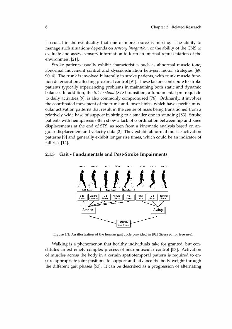
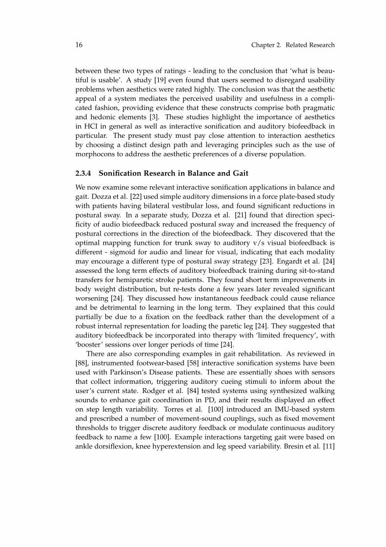
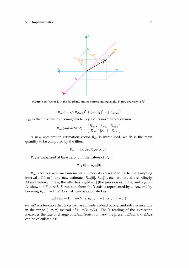
Figure 2.1: An illustration of the human gait cycle provided in [92] (licensed for free use).
Walking is a phenomenon that healthy individuals take for granted, but con-stitutes an extremely complex process of neuromuscular control [53]. Activationof muscles across the body in a certain spatiotemporal pattern is required to en-sure appropriate joint positions to support and advance the body weight throughthe different gait phases [53]. It can be described as a progression of alternating
2.1. Stroke and Rehabilitation 7
weight-bearing limbs, with the body’s center of gravity displacement viewed as theend result of all muscle forces acting on the body [53]. A more detailed accountof kinematic determinants and neural control of normal gait is given in [53]. Ba-sic stepping patterns are generated in the spinal cord, while fine walking controlinvolves several brain regions [20].
A depiction of the gait cycle is given in Fig. 2.1. The basic unit for gait cycles isa stride, a sequence in which each foot alternates between ground contact (stancephase) and non-contact (swing phase) [99]. The stance phase accounts for about60% of a normal gait cycle. A gait cycle is complete when each foot has completedits stance and swing phase, when the starting foot hits the ground again [99]. Ineach stride, there are two occasions when both feet are in contact with the ground(double support time) which collectively account for about 20% of the gait cycle.This is the most stable portion of the cycle, and thus tends to be longer in abnormalgait patterns [99]. A step, on the other hand, is measured from the time one foothits the ground to the time the other hits the ground. The number of steps perminute is called cadence [99].
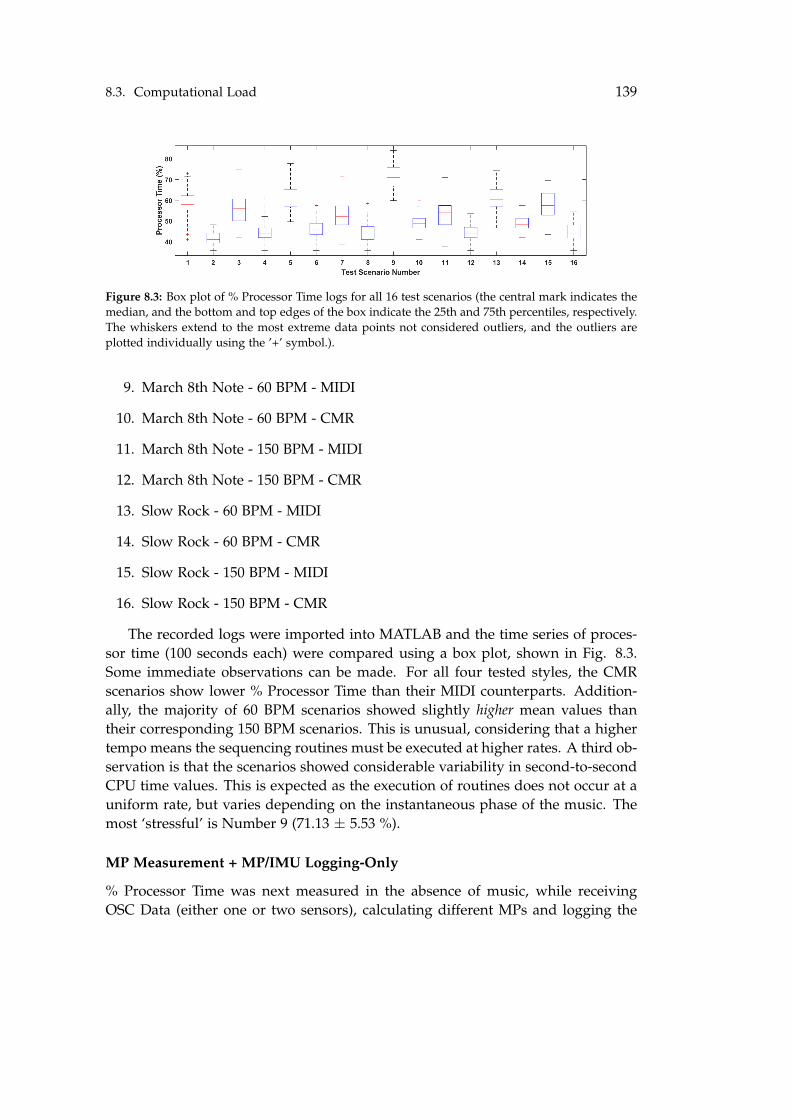
Hemiplegia is an important contributing factor to reduced gait performancepost-stroke [6]. Stroke patients usually have a shortened stance phase and pro-longed swing phase on the paretic side, with sub-normal walking speed and stridelength [75]. Stroke survivors use fewer groups of co-excited muscles (modules) inthe paretic limb while walking as compared to normal controls, causing them towalk more slowly and demonstrate more asymmetry [85]. A full spectrum of ab-normality is seen clinically, depending on the level of muscle weakness, severity ofspasticity, compensatory mechanisms and interactions between these [53]. Amongthese, spasticity and muscle weakness are most common and pose the most severechallenges for patient care [66]. Patients are classified as Fast, Moderate, Slow-Extended and Slow-Flexed walkers and exhibit impairments such as a lack of heelrise during terminal stance, excessive knee and hip flexion in mid-stance, hip hik-ing, leg circumduction and abnormal trunk leaning [66].
2.1.4 Rehabilitation
Brain plasticity is a broad term for the brain’s ability to adapt to environmentalpressure, experiences and challenges, including brain damage [42]. It occurs atmany levels and in the case of stroke is facilitated by post stroke rehabilitative in-terventions [42]. Rehabilitation is essential for stroke survivors to recover mobilityand function so as to live independently, participate in their community and expe-rience fewer secondary complications [34]. Physical activity and exercise have beenestablished to benefit stroke patients in terms of walking ability and balance [63].Current literature suggests that ideal exercise intervention for stroke survivors in-cludes individually-customized combinations of gait, balance and aerobic activitiesthat are appropriate for the patient’s level of impairment [63].
8 Chapter 2. Related Research
Standard motor rehabilitation includes neurofacilitation techniques, task-specifictraining and task-oriented training [87]. They encompass several approaches andfocus on different aspects of motor retraining. The intensity of training varies con-siderably across patients, typically ranging in duration from 30-60 minutes per dayearly after stroke and tending to decrease with time [87]. The rehabilitation periodvaries depending on the degree of impairment and functional deficits [87]. Recov-ery has been observed to be most rapid in the first month post-stroke, slowing insubsequent months and plateauing by 6 months of rehabilitation, after completingwhich approximately 50-60% still experience some degree of motor impairment[34] and dependency [63]. Good outcomes are strongly associated with motivationand engagement from the side of the patient, and setting individual goals may behelpful in this regard [48]. Cognitive function and attention have also been identi-fied as key determinant factors [62]. We now examine specifics of gait and balancein the context of stroke rehabilitation.
Balance Rehabilitation
Balance control is obtained through a unique combination of systems, and corre-spondingly requires task-specific complex rehabilitation [56]. The systematic re-view [56] examines a large number of studies of balance training on acute andsub-acute stroke patients, which focus on static and dynamic balance in both one-on-one and group-based therapy settings - concluding that there is moderate evi-dence of physical improvements with training. Trunk control and sitting balanceare considered key predictors of functional outcome and hospital stay post-stroke[101], with several reviews concluding that trunk training improves them both(as listed in [18]). Aside from finding strong evidence that trunk training improvestrunk control, sitting/standing balance and mobility, Van Criekinge et al [18] foundstrong carry-over effects among them, strengthening the notion that proximal sta-bility is a prerequisite for distal mobility. The effect of STS rehabilitation has beenreviewed [76] and there is moderate evidence that it improves STS duration andweight-bearing symmetry.
Gait Rehabilitation
Lower-limb rehabilitation programs in sub-acute patients mainly focus on gaittraining [41]. Classic rehabilitation techniques can be classified as neurophysicaland motor learning [77], the latter of which includes modern techniques such asrobotic rehabilitation, functional electrical stimulation and brain-computer inter-faces. In neurophysical techniques, the patient acts as a relatively passive recipientwhile motor learning techniques entail active patient involvement [77]. Althoughthere is insufficient evidence to state that one approach is more effective than theother, the combination of different strategies seems to be more effective than over-
2.2. Biofeedback 9
ground gait training alone [6].
2.2 Biofeedback
In a biofeedback system, a person’s bodily functions, parameters and states aresensed, processed and relevant results are fed back to the person through one ormore human senses. The person attempts to act upon this feedback to modify therespective functions, parameters or states in a desired fashion [46]. With recentscientific advances in inexpensive wireless sensor technology, there are now manytypes of sensors capable of quickly and accurately capturing body motion. Thesefacilitate the process of providing immediate biofeedback to focus attention andenhance performance as a form of sensory substitution. Additionally, they allowthe measurement and storage of mobility metrics in daily life not restricted toclinical settings. General factors to consider are monitoring accuracy, sensitivity toimpairments and ease of use for therapists, physicians and patients [36].
Giggins et al. (2013) [31] categorize biofeedback systems as being either physio-logical (PBF) or biomechanical biofeedback (BMBF). The former measures physiologicalsystems such as the neuromuscular, respiratory and cardiovascular systems, whilethe latter entails measurements of movement, postural control and force. The ap-plication developed in this study is a BMBF system, and the discussion will exclu-sively focus on this system category. In rehabilitation, the motor learning focuseson reinstating natural movement patterns after injury [31]. Inertial sensors, forceplates, electrogoniometers, pressure biofeedback units and camera-based systemscan all be used to provide BMBF [31].
2.2.1 BMBF in Rehabilitation
Additional sensory information (i.e. biofeedback) on an individual’s own motionmay improve movement performance by serving as a substitute for the typicalchannels (somatosensory, vestibular, visual) in the nervous system’s sensorimo-tor integration [107]. Movement performance improvements through biofeedbackmay be caused by sensory reweighing processes, in which the relative dependenceof the central nervous system on different senses in sensorimotor integration is al-tered [37]. Biofeedback systems for posture and mobility in older populations arereviewed in [107]. There were indications for larger improvements after trainingbalance, gait and sit-to-stand transfers with biofeedback than without it.
Many researchers have used contemporary technology such as force plates andmotion capture systems to track center-of-pressure or center-of-mass of patients,providing feedback if its position exceeds a pre-defined range or dead-zone [57].Although these devices are effective, their non-portability limits their applicabilityto indoor use only. This requires patients to visit hospitals or laboratories for ther-
10 Chapter 2. Related Research
apy, leading to low adherence and impeding its use in real-world environments[57]. Ma et al. [57] also reviewed multiple studies that developed devices usingwearable movement monitors including inertial sensors and force sensors to mea-sure postural sway/tilt and ground reaction force respectively. They summarizedthat wearable sensors had the advantages of sufficient accuracy, low cost and porta-bility, allowing them to become balance aids in daily life and replace conventionalclinical instruments [57].
In the studies examined by the review [57], inertial motion sensors were used tomeasure postural sway or lower limb joint coordinations in the mediolateral (MLat)or anteroposterior (APos) planes during standing and walking. The majority of re-viewed studies showed improvements in both static and dynamic balance, with ageneral trend that inertial sensors enhanced static balance, and plantar force sen-sors enhanced dynamic balance and were more suited to gait. Moreover, studiesreviewed by Dozza [21] indicated that practicing static tasks had little potential totransfer performance improvements to dynamic tasks [65] and vice versa. This im-plies that two different biofeedback therapies, aimed to static and dynamic balancerespectively may be necessary [21].
Stanton et al. [91] reviewed studies of biofeedback in lower limb activitiesamong stroke patients, and concluded that biofeedback is more effective than usualtherapy and could be used widely in rehabilitation, although long term learn-ing effects remained unclear. The interventions used in their reviewed studiesprovided feedback on EMG activity, linear gait parameters and joint angles [91].Biofeedback was visual, auditory or a combination thereof. Their assessment was amoderate effect of biofeedback in lower limb activities including walking, suggest-ing that information from biofeedback is can supplement therapist communicationand promote autonomy [91]. Tate et al. [96] performed a more general review ofbiofeedback in gait retraining, and found moderate to large effects of kinematic,temporospatial and kinetic biofeedback relative to usual therapy. A highlightedlimitation of the reviewed studies was a lack of long term retention testing.
Ma et al. [57] further suggested that conventional visual biofeedback couldbe discarded in favor of auditory or tactile biofeedback for the sake of portability.The sensors were placed in the lower back region near the location of the center-of-mass, or the shank/thigh. Static and/or dynamic balance were focused on,and the biofeedback modality was visual, auditory, vibrotactile or electrotactile.Balance evaluation was carried out on an immediate basis by both instrumented andnon-instrumented tests, also summarized in [57]. As also pointed out by Dozza[21], new design trends are indeed moving in the direction of auditory and tactilebiofeedback using inertial sensors with the intent of producing cost-effective andportable systems for balance training. Additional reasons favoring this directionare non-reliance on expensive and cumbersome monitors, power cabling and thefact that inertial sensors are one thousand times cheaper (and smaller) than force
2.2. Biofeedback 11
plates [21].
2.2.2 Designing Biofeedback Systems
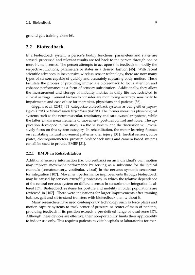
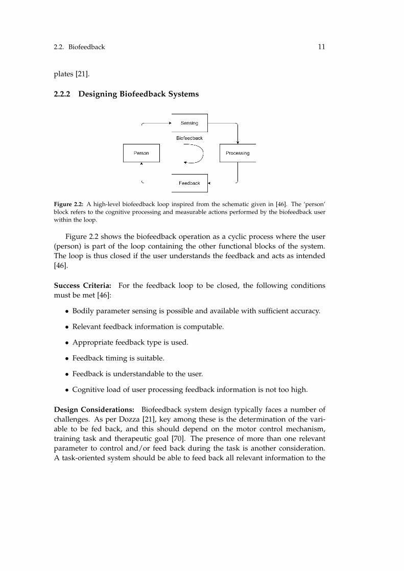
Figure 2.2: A high-level biofeedback loop inspired from the schematic given in [46]. The ‘person’block refers to the cognitive processing and measurable actions performed by the biofeedback userwithin the loop.
Figure 2.2 shows the biofeedback operation as a cyclic process where the user(person) is part of the loop containing the other functional blocks of the system.The loop is thus closed if the user understands the feedback and acts as intended[46].
Success Criteria: For the feedback loop to be closed, the following conditionsmust be met [46]:
• Bodily parameter sensing is possible and available with sufficient accuracy.
• Relevant feedback information is computable.
• Appropriate feedback type is used.
• Feedback timing is suitable.
• Feedback is understandable to the user.
• Cognitive load of user processing feedback information is not too high.
Design Considerations: Biofeedback system design typically faces a number ofchallenges. As per Dozza [21], key among these is the determination of the vari-able to be fed back, and this should depend on the motor control mechanism,training task and therapeutic goal [70]. The presence of more than one relevantparameter to control and/or feed back during the task is another consideration.A task-oriented system should be able to feed back all relevant information to the
12 Chapter 2. Related Research
user without being overwhelming or distracting [21]. Determining how to com-bine various types of information into one variable without being too cognitivelydemanding is paramount [21], and this is particularly relevant for stroke patients.Other challenges include designing a feedback representation that is easy to un-derstand and learn, and does not interfere with task performance [43].
Assessment Considerations: Specifically addressing balance biofeedback, Dozza[21] highlights the importance of quantifying learning, retention and transfer ef-fects resulting from training, in addition to simply immediate task performanceeffects. Depending on underlying pathology and other factors, some individualsmay benefit from biofeedback more than others. Moreover, the extent of perfor-mance improvement due to biofeedback alone is hard to assess (as spontaneouslearning also occurs simply by repetition of a task). A solution to this is the use ofrandomized controlled trials [21].
Implications for Current Study: Examining the success criteria in context withthe available sensing technologies [36, 46], feedback modalities [21] and effect stud-ies [91, 57], it is clear that the criteria of sensing accuracy, feedback type, timing,comprehensibility, cost-effectiveness and portability can be well accounted for byan auditory (or haptic) biofeedback system based on wearable sensors. The con-version of data relations into sound relations is called sonification [35], a processwhich adds expressive qualities to processes that otherwise lack the ability to beheard [43]. By definition, auditory biofeedback is a form of real-time sonificationcategorized as interactive sonification [35], ultimately serving as a form of audi-tory guidance, and so we briefly discuss pertinent aspects of both these researchdisciplines.
2.3 Auditory Biofeedback as Interactive Sonification
2.3.1 Principles of Sonification
Interactive sonification is the subset of sonification defined as "the discipline of dataexploration by interactively manipulating the data’s transformation into sound"[35]. It represents the disciplinary overlap between the research disciplines ofHuman-Computer Interaction (HCI) and Sonification as a whole [35] (see Fig. 2.3).In sonification itself, the key aspects studied are the data transformation technique,the algorithmic implementation and the interaction itself. In biofeedback applica-tions, (physiological) data features are mapped onto acoustical parameters of sonicevents, which is termed as parameter mapping sonification. Interaction-wise, the con-siderations are similar to the success criteria of biofeedback applications in general[46, 35], which makes sense, considering that biofeedback in general and interac-
2.3. Auditory Biofeedback as Interactive Sonification 13
Figure 2.3: The disciplinary overlap between HCI and sonification, inspired from [35]
tive sonification in particular are intimately associated with control loops. Controlloops with sound are critical to worldly experience, as they provide informationabout the environment and synchronize with visual and tactile assessments of ob-jects [35]. The act of making sound may be satisfying to humans because they arein a very tightly responsive control loop, where actions are initiated and constantresults are achieved [35].
A central challenge in sonification design is mapping data onto representa-tional acoustic variables, with attention given to effectively conveying the intendedmessage to the listener [35]. This is primarily determined by the auditory dimen-sion mapping, polarity, scaling, concurrent presentation of data streams, aesthetics,training and perceptual/cognitive ability of the listener (requires special attentionin cognitively impaired target populations such as stroke patients) [35]. In param-eter mapping sonification, the potentially high dimensionality of data and acousticvariables affords a large design space, and effective designs are a compromisebetween intuitive, pleasant and precise sonic representations [35]. Careful datapreparation, mapping function choices and mapping topology selection are crucialconsiderations in parameter mapping sonification design [35].
2.3.2 Principles of Auditory Guidance
Auditory biofeedback systems provide a user with information on bodily states ormovements with the express purpose of guiding the user towards desired states orgoals. Therefore, a brief background on auditory guidance is highly relevant. Asper Sanz et al. [82], sonification designs for guidance purposes may be classifiedas either psychoacoustic or artificial, depending on the data representation techniqueused. The former leverages natural discrimination abilities based on spatial param-eters which makes it more intuitive and natural. The latter maps data attributes toperceptual characteristics of sound such as pitch, loudness and timbre, which af-fords superior task accuracy but entails a longer learning process [73]. An exampleof artificial sonification is Chiari et al. [15], who used an IMU (inertial measure-
14 Chapter 2. Related Research
ment unit) to convert horizontal trunk accelerations into 2D directional auditoryfeedback by manipulating the frequency, level and stereo balance of sinusoidaltones. Mapping functions (linear, exponential, sigmoid) were chosen to suit eachrespective auditory dimension. They too found balance improvements in healthysubjects [15].
Parseihian et al. [73] address several key aspects of guidance sonification designwith a focus on 1D guidance tasks. A central concept is the dissociation of thedata domain from the mapped auditory dimension. This means that rather thandirectly mapping data to the auditory dimension in real-time, the instantaneousdata value is first compared to a ‘target’ value representing the desired systemstate, followed by normalizing by the maximum data value [73]. This converts thedata into a dimensionless quantity that is 0 when the target is matched and 1 atthe maximum distance from the target. This facilitates applications with multiplesonified variables having different units, scales and scaling function requirements[73]. A good example is Costantini et al. [17], who developed and tested anIMU-based biofeedback system that measured MLat and APos trunk inclinationand sonified deviations from a stable central mean position with discrete auditorywarnings. While not precisely the same, they converted 2D projections of trunkposition into discrete auditory feedback zones and essentially sonified the distanceof the trunk projection from the target upright zone [17]. The sounds used weresimple - filtered and modulated noise. Although they only performed short-termevaluations with normal subjects, they found significant improvements in differentconditions of sensory deprivation [17].
Parseihian et al. [72, 73, 74] characterize the information-conveying power of anauditory dimension in terms of its ability to guide the user to the target as quicklyas possible, as accurately as possible and without passing the target. They alsopropose a taxonomy of guidance strategies:
• Basic Strategies: The auditory dimension value is a direct function of distancefrom target. The effectiveness of these strategies is constrained by humanperceptual limits specific to each dimension.
• Strategies with Reference: These include a sound reference corresponding tothe target, enabling target distance estimation without exploring the wholespace. The reference may also be implicit, as with dimensions like harmonic-ity and synchronicity.
• Strategies with Reference and Zoom: These aim to increase precision aroundthe target and reduce identification time by adding a ‘zoom’ effect, createdby strategy duplication in multiple frequency bands [73].
Parseihian et al. [72] compared these different types of strategies in a 1-D guid-ance task, testing their efficacy in terms of guidance speed, accuracy and target
2.3. Auditory Biofeedback as Interactive Sonification 15
overshoot. In the absence of a reference, basic strategies elicited the most over-shoots, while accuracy correlated well with JND (just-noticeable difference) valuesof the tested auditory dimensions - pitch and tempo afforded greater accuracy thanloudness and brightness [72]. Reference and zoom strategies maximized accuracywhile minimizing target overshoots. They highlighted that while some strategiesmay provide precise guidance in a 1D task [73], they may be disruptive when com-bined with another strategy in a 2D or 3D task. The perceptual effects of combiningseveral auditory streams must be considered in guidance design.
2.3.3 Sonification Aesthetics
A tendency of auditory guidance applications to use relatively simple sounds andauditory dimensions has significant implications for the real-world use of interac-tive sonification, especially auditory biofeedback. Parseihian et al. [73] observedthat auditory guidance fails to find its place in commercial applications despitelaboratory promise, and cited the lack of aestheticism in sonification design as alikely cause. Specifically, they attribute user rejection to auditory fatigue causedby the sounds used, or a lack of correspondence to the users’ taste. Indeed, thenotion of user satisfaction has been neglected in guidance aid research. As usertastes are diverse, Parseihian et al. [73] suggest the use of morphocons to conveyinformation through the sonic evolution along auditory dimensions, rather than theactual sounds themselves. This sound-agnostic temporal manipulation makes itfeasible to satisfy individual aesthetic preferences, and allow seamless switchingamong sound palettes without major changes in cognitive load or learning time[73]. The way in which sonic evolution conveys information has a large designspace; relevant sound parameters may be manipulated either as an effect appliedto real sounds or a control parameter to sound synthesis [73].
However, the topic of aesthetics in sonification is also a source of tension in afield that has been traditionally scientific in nature. This centers around the ambi-guity introduced into data when codified using an aesthetic approach (e.g. music)[16]. More ‘functional’ signals (e.g. sine waves and noise) and simple auditorydimensions (e.g. pitch, loudness) have been opted for, owing to a preference forunambiguous data [5]. Neuhoff [68] advocates the ‘bifurcation’ of sonification intodistinct (but not mutually exclusive) paths of either artistic or scientific sonifica-tion. Artistic sonification would focus on more aesthetic aspects of sonic repre-sentation, giving a sense of the underlying data but not always preserving precisedata relations [68]. The other track of ‘empirical’ sonification favors auditory di-mensions where individual differences are smallest and perceptual interactions areminimized [68].
The influence of aesthetics on user experience of an application is examinedfrom an HCI perspective by MacDonald [3]. Several reviewed studies found evi-dence of a firm relationship between aesthetics and usability, with high correlations
16 Chapter 2. Related Research
between these two types of ratings - leading to the conclusion that ‘what is beau-tiful is usable’. A study [19] even found that users seemed to disregard usabilityproblems when aesthetics were rated highly. The conclusion was that the aestheticappeal of a system mediates the perceived usability and usefulness in a compli-cated fashion, providing evidence that these constructs comprise both pragmaticand hedonic elements [3]. These studies highlight the importance of aestheticsin HCI in general as well as interactive sonification and auditory biofeedback inparticular. The present study must pay close attention to interaction aestheticsby choosing a distinct design path and leveraging principles such as the use ofmorphocons to address the aesthetic preferences of a diverse population.
2.3.4 Sonification Research in Balance and Gait
We now examine some relevant interactive sonification applications in balance andgait. Dozza et al. [22] used simple auditory dimensions in a force plate-based studywith patients having bilateral vestibular loss, and found significant reductions inpostural sway. In a separate study, Dozza et al. [21] found that direction speci-ficity of audio biofeedback reduced postural sway and increased the frequency ofpostural corrections in the direction of the biofeedback. They discovered that theoptimal mapping function for trunk sway to auditory v/s visual biofeedback isdifferent - sigmoid for audio and linear for visual, indicating that each modalitymay encourage a different type of postural sway strategy [23]. Engardt et al. [24]assessed the long term effects of auditory biofeedback training during sit-to-standtransfers for hemiparetic stroke patients. They found short term improvements inbody weight distribution, but re-tests done a few years later revealed significantworsening [24]. They discussed how instantaneous feedback could cause relianceand be detrimental to learning in the long term. They explained that this couldpartially be due to a fixation on the feedback rather than the development of arobust internal representation for loading the paretic leg [24]. They suggested thatauditory biofeedback be incorporated into therapy with ‘limited frequency’, with‘booster’ sessions over longer periods of time [24].
There are also corresponding examples in gait rehabilitation. As reviewed in[88], instrumented footwear-based [58] interactive sonification systems have beenused with Parkinson’s Disease patients. These are essentially shoes with sensorsthat collect information, triggering auditory cueing stimuli to inform about theuser’s current state. Rodger et al. [84] tested systems using synthesized walkingsounds to enhance gait coordination in PD, and their results displayed an effecton step length variability. Torres et al. [100] introduced an IMU-based systemand prescribed a number of movement-sound couplings, such as fixed movementthresholds to trigger discrete auditory feedback or modulate continuous auditoryfeedback to name a few [100]. Example interactions targeting gait were based onankle dorsiflexion, knee hyperextension and leg speed variability. Bresin et al. [11]
2.4. Music in Rehabilitation - The Case for Musical Sonification 17
built and evaluated a system for the expressive sonification of footsteps, findingthat harder sonic textures tended to promote aggressive walking patterns and viceversa.
To summarize, several auditory biofeedback studies in balance rehabilitationhave shown significant reductions in postural sway, whether provided on the basisof IMU or force plate data. Direction specificity has been shown to be beneficial,and an optimal mapping function shape has also been suggested [23]. Studies thatgauge long term retention are, however, generally lacking. As for gait, there is ev-idence for the efficacy of instrumented footwear and synthesized walking sounds,as well as suggestions for possible interactions. It is clear that IMU-based systemscan be used to capture important measures of both gait and balance for biofeed-back purposes. Another general tendency among the reviewed studies was thatof using artificial sonification paradigms with simple synthesized sounds, indicat-ing on one hand that these mappings can be effectively learned by patients andpointing to the inherent aesthetics problem on the other.
2.4 Music in Rehabilitation - The Case for Musical Sonifi-cation
The main assertion of this section is that music not only addresses the issue ofaesthetics in sonification but also serves as an effective biofeedback medium dueto its positive physical and psychological effects during exercise (Karageorghis etal. [44]). More importantly, the evolving field of neurologic music therapy hasdemonstrated that music can effectively be applied in the field of rehabilitation aswell.
2.4.1 Why Musical Sonification?
Maes et al. [59] put forward the hypothesis that music is a highly convenientway to present biofeedback on physiological processes, motor kinematic or kineticprocesses and performance parameter output. They present the core functions ofmusic in the biofeedback context as the 3MO model - namely to motivate, moni-tor and modify movement towards specific goals based on reinforcement learningprocesses [59].
Motivation Motivation is imperative in situations that demand high enduranceand perseverance, such as balance and gait rehabilitation [59]. The premise is thatsonification (biofeedback) can take advantage of the strong motivational qualitiesinherent to people’s interactions with music. A known phenomenon is the abil-ity of music to induce physical movement through arousal and motor resonancemechanisms [59]. Music has also been found to affect the limbic system and, in
18 Chapter 2. Related Research
turn, emotional states [40], although this is tied to personal traits, preferences, fa-miliarity and autobiographical memory [47]. However, certain surface features ofsound such as tempo, consonance, mode and texture have been found to affectmusical responses more or less universally [104] and may be used for biofeedbackpurposes. Park et al. [71] investigated how emotional states influenced forwardgait based on familiarity with the music selection. Using consonant and dissonantversions of both familiar and unfamiliar music to participants, they found thatfamiliarity with music interacted with emotional responses to influence gait kine-matics. Gait velocity was significantly greater in the familiar-consonant conditionrelative to familiar-dissonant. However, this difference was not observed betweenthe unfamiliar-consonant and unfamiliar-dissonant conditions [71]. This indicatesthat familiarity is an important mediator of motivation in the face of pleasant orunpleasant modifications to music.
Monitoring Maes et al. [59] outline strategies for multilayer sonification to mon-itor physiological and kinematic parameters. The first leverages human auditoryparallel processing ability by assigning different layers of auditory feedback to dif-ferent physiological processes to increase awareness of their interplay in relation toperformed output. They give the example of an orchestration of muscle synergiesbeing sonified as a well-organized auditory ‘symphony’ [59]. The second strategyrelies on perceptual fusion effects, wherein different auditory layers blend into asingle auditory perceptual object. The focus here is on the cumulative outcome ofall physiological processes, instead of the explicit contribution of each. The idea isthat optimal coordination of processes should lead to a pleasing auditory outcomeand vice versa [59]. The third strategy is related to temporal periodicity-basedfusion. Music often contains repeated patterns with integer-related periodicities,which can be related as phase-locked oscillators [59]. Several physiological andmotor patterns also exhibit a periodic nature, suggesting that music may assist insynchronizing biological oscillators at different periods [59].
Modification Maes et al. [59] summarize two ways in which eventual modifica-tion of motor behavior may occur. The first is guided by reasoning, and requiresthat the learner has an explicit representation of the target behavior, to which ongo-ing behavior can be compared. Learning comprises minimizing the error betweenongoing and target behavior [59]. The ability to modify behavior is thus directlygoverned by the ability to monitor, and this is the typical approach in motor learn-ing. The second approach is based on reinforcement learning and does not requirethat the learner has an explicit representation of the target behavior [59]. Pleasantand rewarding states promoted by music would then serve as attractors of motorbehavior, operating based on mechanisms of brainstem-driven reward and predic-tive processing-driven reward [59]. A prime example is auditory-motor synchro-
2.4. Music in Rehabilitation - The Case for Musical Sonification 19
nization, which depends on the ability to predict the time at which a musical beatis to occur. Successful prediction can lead to strong feelings of pleasure and controlor ‘agency’ [59]. These benefits have been leveraged in technological applicationssuch as the D-Jogger [64] and IM Gait Mate [39].
Novelty, Surprise and Expressiveness From current learning theories, music thatis too repetitive, simple or conventional will not sustain reward responses [59].Dopamine (responsible for feelings of reward) is maximally released when theuncertainty of a reward outcome is maximum, and vice versa [26]. This is relevantboth in the realms of music composition and biofeedback systems, where it isnecessary to include elements of surprise and novelty to support learning, self-regulation and motivation [59]. Expressiveness, too is an important affordance ofmusic in that it affords expressive responses to it. For instance, activating andrelaxing expressions in music [51] have been shown to influence walking velocity.
With these benefits of music, it is appropriate the musical stimulus is con-stantly present throughout the course of an exercise. Biofeedback can be providedby manipulating this music in a continuous or discrete fashion as the case may be.Aesthetically, a stimulative [44] or activating [12] expression appears most suitable,and this has implications for biofeedback system design. Using pre-existing musicis advantageous in that it can be catered to patient preferences and its playbackis computationally inexpensive. However, its artifact-free manipulation is complexand there is limited fine system control over its constituent musical elements. Real-time synthesized music conversely affords straightforward control over not only itsrhythm, tempo and pitch but also individual instrument tracks and their sequenc-ing, synthesis and effect parameters. This allows the creation of interesting andpowerful biofeedback interactions.
2.4.2 Neurologic Music Therapy
Neurologic music therapy (NMT) is defined as "the therapeutic application of mu-sic to cognitive, affective, sensory, language, and motor dysfunctions due to diseaseor injury to the human nervous system" [99]. It is based on neuroscientific modelsof music perception and production, as well as the influence of music on changesin non-musical brain and behavior function. An advantage of using music in ther-apy for the elderly is that music is painless, non-intrusive, easily accessible andcost-effective [52]. Treatment techniques are adapted to suit the patient’s needs,and directed towards non-musical therapeutic goals. Translational biomedical re-search in music has led to the development of clusters of evidence showing theeffectiveness of certain interventions, which were later classified into a system ofabout 20 techniques that make up NMT, such as Rhythmic Auditory Stimulation,Patterned Sensory Enhancement and Therapeutic Musical Instrument Performance(see Appendix A). Music is processed by the brain in a highly distributed fashion
20 Chapter 2. Related Research
from spinal and subcortical areas to cognitive and motor control centers. The the-oretical models of NMT are fundamentally based on an understanding of musicperception processes. NMT techniques and principles are compatible with bothtraditional and new concepts of motor rehabilitation grounded in motor learningrules [99].
2.4.3 Musical Biofeedback Research
Studies employing musical biofeedback are rare, and some relevant ones are re-viewed here - although these are not necessarily stroke rehabilitation-related. Somestudies performed simple manipulations of existing music pieces, for example byadding noise [8] or adjusting audio quality [33] to sonify respiratory rate. Loren-zoni et al. [55] sonified running cadence compliance through the addition of noiseto pre-selected songs of the participants’ preferred genre. They found that thefeedback was capable of altering running cadence significantly better than verbalinstructions. In a pilot study, Schedel et al. [89] tested the capability of rhyth-mic distortion, timbral distortion and white noise added to the preferred music ofParkinson’s Disease patients. They found that the patients could perceive thesedistortions and utilize this information for error correction with similar speed andaccuracy to healthy peers. The D-Jogger [64] sonifies detected step cadence bysynchronizing pre-existing music to detected gait patterns through digital signalprocessing. The tempo and phase manipulations make it possible to walk/run intime with the beat. Sensors measure gait timing, and tempo-appropriate music isselected [64]. A phase vocoder then adjusts the tempo and phase of the music tomatch the gait timing. Interaction with the D-Jogger is founding to have a strongrewarding effect as the synchronization provides energizing and satisfying feelingsof agency [52]. The ‘Jymmin’ system developed by Fritz et al. [29] provides musi-cal biofeedback when interacting with fitness machines, by mapping movements ofthe machine to parameters of effects acting on electronic dance music loops. Theseincluded band pass filters and pitch-shifters in Ableton Live. On experimentallycomparing the use of this system with passive music listening during exercise,they found that using the system reduced perceived exertion [29], pain [28] andimproved mood [30].
Other studies employed real-time synthesis approaches, through which it iseasier to exercise finer control over sonic parameters of music. Gorgas et al. [78]mapped gait characteristics to musical notes, which led to improvements in ca-dence and velocity in Parkinson’s Disease patients. Bergstrom et al. [7] testedthe efficacy of music as a sonification signal in arousal modulation. Their designsonified measured heart rate through changes in music tempo and amplitude, andtheir evaluation compared this design with plain music listening and a simplesine pitch sonification. They concluded that the effects of musical sonification forarousal modulation were superior to those of music alone, and as effective as the
2.5. Defining an Interaction in the Present Context 21
sine sonification. They noted that the musical design had the added advantagesof drawing attention and providing variety in the feedback signal, which wouldserve to reduce auditory fatigue [7]. Yu [106] sonified heart rate as speed, empha-sis and inter-beat delay in arpeggio chords and note pairs respectively. While thesystem was found to be effective at its purpose, participants, however, found thebiofeedback stressful possibly due to the sonification design strategy and unfamil-iarity of the audio forms [106]. The author emphasized that the simplicity of themusical biofeedback was not comparable to the richness of a properly composedpiece of music, which may have also led to tiredness among participants [106].The ‘moBeat’ system developed by van der Vlist et al. [102] provided heat-ratebiofeedback during a cycling exercise by supplying pedalling-synchronized syn-thetic music and giving feedback on training intensity compliance through alter-ing the richness of musical layers. In addition, synthetic tones were given outsidethe compliance zone to direct the user on cycling speed. The system was foundto be comparable to a reference system in terms of compliance [102]. They foundthat the music provided a natural distraction away from the exercise itself as seenthrough fewer distress cues, in addition to eliciting greater motivation overall. Theauthors did, however, stress the importance of providing preferred music to theusers [102].
2.5 Defining an Interaction in the Present Context
Although simple auditory biofeedback has been researched with stroke patients,there lacks a design framework for musical biofeedback applications catering tothis group. In other words, it is neither known how movement-music interactionscan best be designed to fit into existing gait and balance training regimes, norhow effective these interactions are from a therapeutic standpoint. The former is anecessary precondition for the latter.
It is important to define the term ‘interaction’ more specifically for the purposesof the present study, as the term can refer to entities that hold distinct meaningsdepend on the purpose and context. The way in which the term is construedwill influence the notion of what constitutes a good interaction and in turn, thethought process underlying interaction design [38]. In an essay, Hornbæk et al.[38] discussed the various ways in which human-computer interaction can be de-fined, formulating interaction as dialogue, transmission (of a message over a noisychannel), tool use, embodiment, experience and optimal behavior. Glancing at keyphenomena, constructs and good interaction characteristics of each of them, it isclear that they have much in common and that most interactions can be seen as acombination. A musical biofeedback system for stroke patients, for instance canclosely related to the following subset of these terms [38]:
1. (Patient Perspective) A control system that "interactively minimizes (move-
22 Chapter 2. Related Research
ment) error against a reference (state)".
2. (Patient Perspective) An "ongoing stream of expectations, feelings and mem-ories", or an experience.
3. (Clinician Perspective) "a sender (patient) sending a message (movementinformation) over a noisy channel".
4. (Patient Perspective) "Acting and being in situations of a material and socialworld", or embodiment.
As the theoretical foundation of the present study constitutes biofeedback loops,auditory guidance, aesthetics and musical experiences for therapeutic purposes,the first three definitions seem to fit it readily. However, the embodied perspec-tive of lived experiences cannot be neglected due to its profound impact on userexperience, particularly for a target group with cognitive impairments. Acknowl-edging this, the majority of interaction design is anticipated to be performed from athird-person perspective as a collaborative design process is not feasible at present.Therefore, ‘interactions’ henceforth imply the first three definitions, with "rapidand stable convergence to target state", "satisfaction of psychological needs andmotivation" and "maximum throughput of information" respectively constituting agood interaction [38], although the patient perspective is of primary importance.
2.6 Own Past Work
In previous work [79], we developed a proof-of-concept application which synthe-sized a multitrack ensemble of instrumental electronic music. Gait was capturedusing single bilateral force sensors, and temporal deviations were directly sonifiedas unpleasant modifications to the music such as noise, disturbance notes and ringmodulation effects. The music was pre-programmed and basic, and it was notpossible to customize mappings or adjust the system to individual abilities. Eval-uation showed that the sonifications were hard to perceive. A second more elab-orate proof-of-concept system [80] was developed with a series of foot-switches.This time, the music was generated in a pseudo-random manner, but still basicand electronic-sounding. Temporal gait deviations were sonified by modifyingenergetic qualities of the instruments designed according to motor-mimetic em-bodiment theories. The gait parameter mappings were individual-baseline specificand customizable. Pilot tests showed that the sonifications were easily perceptiblefor young, healthy individuals, but that the foot switches and physical hardwarewere cumbersome and sometimes uncomfortable or restrictive [80]. In general, themusic also received poor aesthetic ratings. Clinical tests with real patients werenot conducted in either study, and the hardware prototypes were generally fragilein the face of wear-and-tear.
Chapter 3
Problem Analysis
At this point, we define the broad goal of this research as the design, developmentand evaluation of a biomechanical biofeedback application that provides real-timefunctional kinematic feedback through the medium of music, with particular focuson the development of movement-music interactions suitable to therapy.
3.1 Outcomes, Delimitation and Final Framing
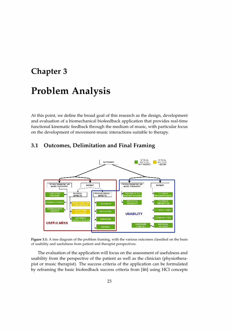
Figure 3.1: A tree diagram of the problem framing, with the various outcomes classified on the basisof usability and usefulness from patient and therapist perspectives.
The evaluation of the application will focus on the assessment of usefulness andusability from the perspective of the patient as well as the clinician (physiothera-pist or music therapist). The success criteria of the application can be formulatedby reframing the basic biofeedback success criteria from [46] using HCI concepts
23
24 Chapter 3. Problem Analysis
of usefulness and usability [3] to accommodate the perspectives of both patients andclinicians. These two terms have much in common but a key distinction. Useful-ness is defined as "the extent to which a system’s functions allow users to completea set of tasks and achieve specific goals in a particular context of use". Usability,on the other hand, pertains to whether the system does so with "effectiveness,efficiency and satisfaction" [3].
On the basis of these definitions, the success criteria of the biofeedback appli-cation from both perspectives are re-framed in the current context and classifiedinto usefulness and usability criteria, as depicted in Fig. 3.1. Most of these criteriaare either self-explanatory or have been discussed, with the exception of usefulnesscriteria from the therapist perspective. These primarily relate to whether or not theapplication is capable of sensing all movement behaviors relevant to the activity(including phenomena that are hard to perceive visually), and making them ex-plicit through the musical feedback. Psychological effects on patients can be seenon one hand as usefulness criteria as they are positive outcomes resulting directlyfrom the interactions, and on the other as usability criteria, as they facilitate theachievement of superior task performance and movement quality. If this diagramwere to be condensed into a problem statement as per PICO(T) guidelines, it wouldappear as follows:
Original Problem Statement: How does the application of a user-tailored musi-cal biofeedback system impact physical movement parameters and subjective ex-perience in balance and gait rehabilitation of hemiparetic stroke patients? Howuseful is the auditioning of movement phenomena to a clinician?
And what music interaction schemes and feedback strategies are most suitedto common training activities in terms of meaningfulness, perceptibility, timing,individual tailoring, cognitive load, relevance and practical feasibility?
Necessary Delimitation: In Fig. 3.1, criteria are also categorized on the basisof whether ethical approval is required to evaluate them or not. Enquiries to theRegion Nordjylland Ethical Committee helped clarify that the majority of criteriawould not require official ethical approval in order to be evaluated, with the ex-ception of physical effect measurements, both short and long term. Although anethical application was framed, it could not be submitted to the committee for ap-proval within the time-frame of this project, but will be submitted to allow futurework to proceed. Another constraint was the fact that the project did not havethe financial support to enlist the assistance of physiotherapists for extended pe-riods of time for testing. All evaluation therefore had to be conducted in limitedtime-frames with small numbers of patients (5-7 in a single day per iteration). Inthe light of these restrictions, the scope of the research was modified to excludeeffect measurements altogether, and focus exclusively on the design and develop-
3.1. Outcomes, Delimitation and Final Framing 25
ment of intuitive, relevant and flexible interactions for gait and balance training.The remaining success criteria were left intact, and the final problem statement isreformulated as follows:
In balance and gait rehabilitation of hemiparetic stroke patients, what mu-sic interaction schemes and musical biofeedback strategies are most suited tocommon training activities, in terms of subjective experience, meaningfulness,perceptibility, timing, individual tailoring, cognitive load, relevance and practi-cal feasibility? How useful is the auditioning of movement phenomena from aclinician’s perspective?
Chapter 4
Methods
We now define a set of broad requirements that the developed technology mustfulfill:
• Generation of suitable and user-customizable musical stimuli.
• Non-invasive, lightweight and comfortable movement sensing hardware ca-pable of capturing the required kinematic data for biofeedback purposes.
• An available set of intuitive and perceptually salient musical feedback strate-gies.
• Real-time mechanisms for relevant kinematic parameter calculation from theraw sensor data.
• Flexible and user-customizable mapping from kinematic parameter domainto auditory feedback domain.
4.1 Research Methodology
Fulfilling the above requirements will involve facing domain-specific challengesrelated to designing music technologies for healthcare, particularly when elderlypeople are involved who are primarily non-musicians. Problems with budgets,ethical constraints, logistics and healthcare system structure, variability in the abil-ities of patients, as well as the stigma experienced by prospective participants ofbeing approached as patients are challenges to this form of research [52]. These un-familiar technologies can also bring ethical concerns and confidence issues, whichmust be addressed [52]. For these reasons, a participatory approach to this researchappears most suitable.
As reviewed by [54], old people have traditionally been categorized as research‘subjects’, pointing to an imbalance of power between them and the researcher. Par-ticipatory research (relevant when the research is conducted in collaboration with
27
28 Chapter 4. Methods
the group being studied) ethically values the capabilities of the elderly and ad-vances their autonomy, allowing them to appraise project relevance and increasingthe adoption of research outcomes [54]. Elderly individuals generally participatein research with the intention of giving, as well as social participation to combatloneliness. Recruitment and retention of participants over the course of a studycan be challenging, and it is important for researchers to be respectful, flexible andappreciative of the diversity among the elderly [54]. A more detailed treatment ofthe matter can be perused in [54].
Lesaffre et. al. [52] explain how participatory user-centered studies are graduallyseen as the staple research methodology for music-based mediation technology.This is, in brief, "a joint activity of a cross-disciplinary team of stakeholders thatcooperate throughout the entire research procedure" [52]. The design process isguided by principles of participatory design, meaning stakeholders with differentareas of expertise have a deciding vote in the design process. Target patient groupsmust be narrowed down to patients who enjoy music, are sensitive to music rewardexperiences, have a positive advantage towards new technology, have adequatemotor skills and so forth [52].
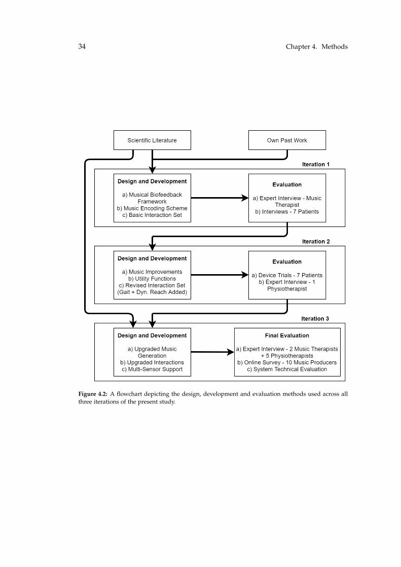
The methodology of the current study is firmly rooted in this philosophy; itis carried out in an iterative manner over a total of three design and developmentcycles (shown in Figure 4.2). Stakeholders such as stroke patients and clinicianswere enlisted during evaluation in all these iterations, with the exception of thethird one where patients could not be accessed due to the COVID-19 situation inDenmark.
4.2 Methods Used in Current Study
4.2.1 Terminology Clarification
For the sake of brevity, certain repeating terms will henceforth be shortened andan explanation is provided in Fig. 4.1.
4.2.2 Design and Implementation Philosophy
Musical Stimulus
As reviewed, musical biofeedback studies have used either pre-existing music orreal-time synthesized stimuli. Preexisting music is advantageous in that it canbe catered to patient preferences and its playback is computationally inexpensive.However, its artifact-free manipulation is complex and there is limited fine systemcontrol over its constituent musical elements. Real-time synthesized music con-versely affords straightforward control over not only its rhythm, tempo and pitchbut also individual instrument tracks and their sequencing, synthesis and effect
4.2. Methods Used in Current Study 29
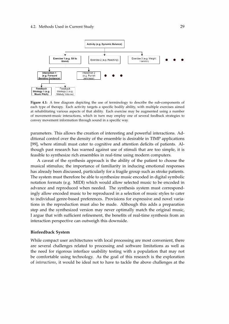
Figure 4.1: A tree diagram depicting the use of terminology to describe the sub-components ofeach type of therapy. Each activity targets a specific bodily ability, with multiple exercises aimedat rehabilitating various aspects of that ability. Each exercise may be augmented using a numberof movement-music interactions, which in turn may employ one of several feedback strategies toconvey movement information through sound in a specific way.
parameters. This allows the creation of interesting and powerful interactions. Ad-ditional control over the density of the ensemble is desirable in TIMP applications[99], where stimuli must cater to cognitive and attention deficits of patients. Al-though past research has warned against use of stimuli that are too simple, it isfeasible to synthesize rich ensembles in real-time using modern computers.
A caveat of the synthesis approach is the ability of the patient to choose themusical stimulus; the importance of familiarity in inducing emotional responseshas already been discussed, particularly for a fragile group such as stroke patients.The system must therefore be able to synthesize music encoded in digital symbolicnotation formats (e.g. MIDI) which would allow selected music to be encoded inadvance and reproduced when needed. The synthesis system must correspond-ingly allow encoded music to be reproduced in a selection of music styles to caterto individual genre-based preferences. Provisions for expressive and novel varia-tions in the reproduction must also be made. Although this adds a preparationstep and the synthesized version may never optimally match the original music,I argue that with sufficient refinement, the benefits of real-time synthesis from aninteraction perspective can outweigh this downside.
Biofeedback System
While compact user architectures with local processing are most convenient, thereare several challenges related to processing and software limitations as well asthe need for rigorous interface usability testing with a population that may notbe comfortable using technology. As the goal of this research is the explorationof interactions, it would be ideal not to have to tackle the above challenges at the
30 Chapter 4. Methods
present stage. An instructor-based architecture with remote processing by a pow-erful computer eliminates the processing challenge. To be clear, the term instructorin this context would normally mean a physiotherapist, but the present goal is onlyto create an interface to test interactions in collaboration with a physiotherapist,who will not directly operate the technology at this stage.
With the difficulties experienced using force sensors and foot-switches in ourown previous studies [79, 80], the chosen approach here is that of IMU unitswith multiple axes of measurement (both accelerometer and gyroscope), capableof wireless transmission at a sufficient rate. The inertial data obtained from thesesensors can be processed in different ways to obtain an array of parameters relatedto orientation, movement quality, quantity and timing. For instance, trunk inclina-tion, sway velocity, jerk quotients, foot swing and heel-strike impact can be readilycomputed. An appropriate IMU product must be chosen, and a robust and safemounting mechanism must be developed for different parts of the body. The nextconsideration is whether to use existing digital audio software for system control(e.g. Ableton Live used by [102]) or to develop a stand-alone application fromscratch. Using existing software can save development time considerably, as cer-tain key functionalities are already covered such as external controller interfacing,audio synthesis, effect manipulation and mixing. On the other hand, the complexprocessing of IMU measurements, data transformation prior to feedback mappingand precise design of feedback behaviors can be difficult to achieve through suchsoftware. The chosen approach is therefore to build a software application fromthe ground up. The added advantage of this approach is that many developedfunctional elements can be reused when porting the system to other platforms(e.g. mobile) in future research.
Musical Feedback and Mapping
Philosophy: The musical feedback in the current application broadly aims to pro-vide the patient with the following in a context-dependent manner:
• Concurrent feedback on position and movement quality.
• Cyclic feedback on movement periodicity.
• Auditory cues for movement (rhythmic or contextual).
The musical feedback would generally classify as artificial sonification [82], asthere is no strict psychoacoustic correspondence between the sonification and theexercise. The challenge lies in designing feedback that is clearly perceptible andintuitive to the patient in context with the ongoing exercise, both of which arecritical to closing the biofeedback loop. A useful starting point comes from Maeset. al. [59], that is the notion of mapping desirable movement behaviors to pleasant
4.2. Methods Used in Current Study 31
auditory states and vice versa. While this is apparently simple, subjectivity in theperception of pleasant auditory states combined with cognitive deficits interferingin this meaning-making process are foreseeable obstacles.
Years of music listening experience means that most individuals have a robustinternal schema of how music ‘ought’ to sound, in terms of consonance, rhyth-micity, harmonicity, internal synchronicity and timbre. Universal agreement aboutthe phenomenon of dissonance, for instance, has already been discussed. This in-ternal schema can serve as an implicit reference for pleasant auditory states, whiledegradations applied to any of the above musical dimensions can represent un-pleasant states. These degradations will be effected by manipulating synthesis,envelope and effect parameters to achieve specific perceptual results. This is themusical equivalent of the strategies with reference defined by Parseihian et. al. [73]and fits well with the philosophy proposed by Maes et. al. [59]. Of paramountimportance is that the unpleasant states are distinct enough from pleasant states tobe unambiguously perceived and understood by individuals who are elderly andcognitively impaired.
Meaning-Making Through Music: Due to the temporal and spectral complexityof music, musical sonification is not likely to provide the same level of precisionin data representation as, for instance, pitch and tempo manipulations of simplewaves. But what must be stressed is that it is not intended for the sonificationto be used in this way. As it is, the auditory system is not as sensitive to smalldifferences as the visual system [68] and it is perhaps futile to attempt to providepinpoint positional information through musical sonification. It is more expedientto use music to assist the patient in interpreting the meaning of their movements,so he/she can take corrective action if necessary. This would fall firmly underNeuhoff’s definition of artistic sonification [68].
On one hand, this could be seen as reinforcement learning as per Maes et. al.[59] as the patient is directly encouraged in the direction of desirable behaviors.But on the other hand, they have an implicit reference for how desirable behaviorshould sound, and attaining that sound can involve a reasoning process describedby motor learning theory [46]. Borrowing from principles of PSE [99], the meaning-making process is facilitated by intuitive movement-music mappings. Sonificationneed not necessarily be restricted to either pleasant or unpleasant states. Non-rhythmic movement cues, for instance can be given through ‘neutral-sounding’momentary artifacts in the music (with neither positive nor negative intendedmeaning).
Flexible Mapping Framework: Conveying kinematic ‘meaning’ to patients throughmusical dimensions requires that the technology is first able to understand whethera measured quantity constitutes a desired behavior pattern or not. This is further
32 Chapter 4. Methods
complicated by the fact that different activities and exercises entail different be-havior types, and stroke patients have differing abilities and achievable therapeuticgoals. This indicates that a direct and rigid mapping between kinematic param-eters and musical dimensions is unlikely to suit the needs of the diverse patientpopulation. Moreover, the goal of building and testing interactions requires thatall kinematic parameters and musical dimensions are mutually mappable, whichis a challenge as they have different ranges and perceptual scaling factors.
The solution to both these problems is a flexible parameter mapping frame-work, where the data domain is dissociated from the audio domain by data nor-malization and sonification of measured movement error, as prescribed by Parsei-hian et. al. [73]. A useful tweak to this system is to allow the system to workin error correction mode as well (relative to a threshold) [46]. Thus, all measuredkinematic parameters will be transformed from their own value ranges to a normal-ized range whose extremes represent desired and undesired behavior respectively.Hence, all auditory feedback strategies can be designed with appropriate mappingfunctions for compatibility with this system.
Feedback Dimensionality: A final consideration is the feedback dimensionality,meaning how many kinematic parameters can be mapped to auditory dimensions.While multidimensional mappings are possible in music [59], Parseihian et. al. [73]warn about detrimental interactions between auditory streams and dimensions.The choice adopted through the entirety of this project is 1-D mapping, where asingle kinematic parameter is mapped to a parameter in the auditory domain. Thisis primarily done to reduce cognitive load on patients who may have all manner ofattention deficits, perceptual impediments and cognitive difficulty. The system willbe built to allow scalability to multiple dimensions, but the interaction foundationswill be laid in a 1-D architecture.
4.2.3 Evaluation Procedures
Every iteration undergoes one or more evaluation procedures at its end. The eval-uation data are systematically documented in the form of sensor logs, A/V record-ings and interview data for analysis.
Participatory Studies with Patients: Groups of stroke patients admitted to Neu-roenhed Nord, Region Nordjylland were approached to help evaluate the first andsecond iterations. The evaluation activities were structured interviews and actualprototype trials respectively, and 6-7 patients took part in each case. The purposeof these was to assess the developed interactions in real-life training scenarios. Ingeneral, sub-acute patients were chosen, ethical guidelines were respected, andparticipants were informed about the activities a week in advance, with writtenconsent obtained from each of them.
4.2. Methods Used in Current Study 33
Expert Interviews with Clinicians: Expert interviews were conducted with mu-sic therapists and physiotherapists at each stage. The purpose of these interviewswas to showcase the developed interactions and gauge the main outcome measuresin Chapter 3. The interactions were demonstrated either in real life (Iteration 1, 2),or through high quality video recordings (Iteration 3). These interviews formed theprimary evaluation procedure in Iteration 3, where five physiotherapists and twomusic therapists were interviewed remotely. All interviews were recorded with theparticipants’ permission. The transcriptions were coded by a single coder (author)by an inductive approach into a hierarchical coding scheme.
Technical Testing: This was a round of tests conducted on the application (Iter-ation 3) to assess key technical parameters of the system, such as latency, com-putational performance and sensor range. Overall system latency was measuredduring different interactions by frame-wise video and audio analysis. Computa-tional performance was measured as processor time, and logged using Windowsbenchmarking software. Sensor range was measured in terms of the percentage ofreceived IMU data packets in a short time-frame.
Online Survey - Music Production: A brief 15 minute online survey was pre-pared and shared with music producers, so as to obtain feedback on the produc-tion values of the system-synthesized music (final iteration only). Questions wereposed based on stylistic and aesthetic choices, as well as audio-specific aspects suchas frequency and dynamic balance. Five synthesized styles of music were chosenand assessed in this manner.
34 Chapter 4. Methods
Figure 4.2: A flowchart depicting the design, development and evaluation methods used across allthree iterations of the present study.
Chapter 5
Iteration 1
5.1 Aims
The first iteration aims to design and implement a fundamental framework thatcontains the key components of a musical biofeedback system, including a rudi-mentary set of balance training interactions. From an implementation standpoint,the aim is to achieve the following functionality in real time:
• Wireless inertial sensing
• IMU signal analysis
• 1-D sonification
• Basic set of auditory feedback strategies
• Music generation framework
• Lightweight music encoding framework
• Tempo/rhythm (groove) manipulation
5.2 Design
5.2.1 Overview - System Structure
The system has a distributed structure [46], wherein the processing and monitor-ing are performed at a ‘remote’ location, a laptop in this case, while sensors (andpossibly feedback actuators) are mounted on the user. The system design is simplyillustrated in Fig. 5.1, depicting a lightweight wireless IMU attached to the trunkof the user. A laptop application acts as the hub for inertial data reception, pro-cessing, music synthesis and sonification. It connects to a loudspeaker or pair ofheadphones which acts as the feedback actuator.
35
36 Chapter 5. Iteration 1
Figure 5.1: A simplified depiction of the system, showing a wireless IMU unit mounted to the trunkof a patient, as well as the information transmission and reception channels.
5.2.2 Sonic Interaction Set - v1
As a starting point, only static and dynamic balance training contexts are consid-ered in this first iteration. From literature, static balance training exercises includemaintaining a position of equilibrium under a variety of conditions (sitting, stand-ing, eyes closed, etc.). An example of a dynamic training exercise on the otherhand is trunk bending (to pick up or place a distant object for instance). Withthe current system, an array of sonic interaction concepts with suitable feedbackstrategies is conceived and short-listed for evaluation. The interaction concepts areas tabulated in Table 5.1 and explained below. Note that the measured movementparameters and feedback strategies are explained later in this chapter.
• Static Balance - Posture Feedback - Negative: The objective of static balanceexercises is to help maintain upright posture. This feedback concept is pro-vide negative feedback if upright posture is lost, whose intensity is directlyproportional to the loss of posture. Posture can be measured in terms ofMLat/APos trunk inclination angle. The goal of the patient is thus to keeptheir trunk inclination angle below a target threshold, failing which, nega-tive reinforcement is provided through the music. The music itself soundscompletely ‘normal’ while the patient remains within the target threshold.Appropriate music feedback strategies are the ones which result in unam-biguous degradation of music quality.
• Dynamic Reaching - Posture Feedback - Positive: The objective of reachingexercises is to attain a certain magnitude of angular trunk bending en route topossibly performing a functional task such as grabbing or touching an object.This bending may either be in the APos or MLat direction, and can similarly
Table 5.1: An overview of the activity-wise interaction possibilities in Iteration 1, along with rele-vant MP and AP choices in each case. Listed AP’s are only tested examples, and do not cover allpossibilities.
be measured using the corresponding inclination angle. The key differencein this case is that exceeding the target threshold is a desired behavior in thistraining context, and will result in positive feedback. Although one possibilityis to provide negative feedback under the threshold and normal soundingmusic above (exactly opposite to the previous concept), it is not fair to punisha patient for sitting upright as the upright phase is a valid part of the reachingexercise. While it does make sense to provide normal sounding music abovethe target, suitable feedback strategies below the target are those that aremore ‘neutral’.
• Static/Dynamic Balance - Jerkiness Feedback - Negative: The third and finalinteraction concept involves giving direct negative feedback if the measuredjerkiness during any training exceeds the target threshold. Movement qual-ity during training is of great importance, and sudden jerky movements ormovement phases can indicate instability. Jerkiness is a quality that is hardfor a therapist to give real-time feedback on (or even see) due to its rapid na-ture, but the IMU can sense it with ease. The goal of the exercising patient isto keep their measured scalar jerk under the custom-defined target threshold,failing which rapid negative feedback will be provided for the duration of thejerky movement and proportional to jerk magnitude. The most appropriatefeedback strategies are found to be the ones that by their nature sound most
38 Chapter 5. Iteration 1
‘jerky’, and correspond directly to the underlying movement.
Most initial design choices have been discussed and motivated in Chapter 3; themovement sensing approach of choice is that of wireless IMU-based measurement.A choice of movement measures is offered, ranging from orientation to sway veloc-ity and jerk. The movement-music mapping is one-dimensional and keeping withthe normalized target error framework described by Parseihian et. al. [73], withany movement-feedback mapping strategy made possible in the user interface. De-sired movement behaviors can be changed in real-time, allowing the biofeedbackto function in error-correction mode as well [46]. The remainder of this sectionfocuses on the design philosophy for music representation and generation.
5.2.3 Music Generation
For a coordinated and balanced music synthesis output, the following broad ele-ments are necessary:
• Multi-Instrument Music Structure Data: Information required to synthesizea specific music piece. May be stored within the application or loaded fromexternal files, or a combination.
• Music Sequencing: Temporally organized musical structure information formultiple instruments.
• Music Synthesis: Architecture to realize multitrack musical structure infor-mation as synthesized mono or stereo audio tracks, including melodic orpercussive instruments.
• Music Mix and Master: The output of the individual synthesizers must begiven individual dynamics processing, equalization, gain adjustment andstereo panning, followed by stereo mixdown and master processing, yield-ing a single stereo output.
Musical Structure Representation The overall evolution of a piece of music is thesum of the individual evolutions of each of its constituent instruments. Of course,the real-life performance of any musical instrument would possess multiple di-mensions which would need to be considered for accurate performance captureand reproduction. Symbolic representations such as MIDI are used in modern mu-sic production to represent instrumental performances, and can be input to virtualinstruments to simulate these performances with an appreciable degree of real-ism. Due to its simplicity and lightweight structure, MIDI is used as the primaryinspiration for the custom lightweight notation used in the present iteration.
MIDI captures polyphonic musical performances in the form of a sequence ofmessages that are ordered as they temporally appear. The timeline is discretized
5.3. Implementation 39
in a tempo-dependent fashion, into ‘ticks’ that equally divide intervals of musi-cal time with fine granularity (typically 960 ticks per quarter note). Every MIDImessage has a timestamp represented in ticks, and the varied message types relateto note onset/offset, articulation and synthesizer control. Speaking specifically ofnote onset/offset, these are contained in the interval between ‘note-on’ and theircorresponding ‘note-off’ messages, which specify note number (0-127 range) andnote velocity (0-127 range). It is possible to encode information pertaining to bothpercussion and melody instruments in MIDI.
Novel Simplified Scheme: Simply building a MIDI library would ordinarily be avery time-consuming task as a large amount of multitrack information would needto be encoded for each song, in addition to the need for a software framework forthe reading and tempo-accurate playback of multitrack MIDI files. The use ofreadymade MIDI files from free websites is also less-than-ideal, considering thelack of standardization found among such files in terms of tracks, voicing and de-tail. Hence, there is a need to design and implement a simpler and faster methodfor the representation of music pieces. A new simplified scheme is developed,termed as Compact Music Representation (CMR). The specifics of the representationdesign are given in Appendix B. A separate dedicated JUCE application is imple-mented for the encoding of music pieces in this scheme, discussed in greater detailin the next section. Music files are stored in the CSV format (<3 KB) that can beloaded for real-time playback.
5.3 Implementation
The software requirements for this iteration are fulfilled in the form of two separatestandalone Windows applications:
• Music Encoder Application: This facilitates the creation of CMR files. It al-lows the user to audition musical passages, modify existing files and exportCSV files in CMR format for audio reproduction by the biofeedback applica-tion.
• Biofeedback Application: This is where sensor data reception, processingand feedback generation are collectively carried out. It has a user interfacefor music selection, playback and biofeedback control.
Both applications are built in C++ using the JUCE 1 programming environ-ment with Microsoft Visual Studio 2017. JUCE is chosen for its wide selection ofclasses and libraries that expedite the creation of user interfaces as well as sensordata reception, accurately timed callbacks and advanced data handling. For audio
1JUCE. url: https://juce.com/
40 Chapter 5. Iteration 1
Figure 5.2: The M5Stack Grey Device (courtesy Adafruit)
synthesis, both applications use FAUST, a domain-specific functional audio pro-gramming language with its own libraries for efficient audio synthesis, filteringand routing. FAUST is interfaced with JUCE by using the Faust2Api commandin the FAUST compiler, which compiles FAUST .dsp scripts as JUCE-compatibleDspFaust classes in C++. The applications are developed as VST plugin projects inJUCE, which also create standalone applications on compilation.
5.3.1 Movement Sensing
The movement sensing functionality was implemented as part of the Prototyping and Fab-rication course project in the 9th Semester.
Hardware Description
The sensing hardware must fulfill the following requirements:
• Low-latency wireless transmission
• Ease of mounting and portability
• Sufficient battery life to last the duration of a training session.
• Low cost
• Scalability (no. of sensors)
With these in mind, the chosen sensing device is the M5Stack Grey 2. Withan ESP32 core, it carries a multi-axis IMU sensor (MPU9250+BMM15). The ESP32has a hybrid Bluetooth/Wi-Fi chip programmable in the Arduino programmingenvironment. The M5Stack device is relatively small (54x54x20mm), and has a320x240 LCD screen, a small loudspeaker and three programmable buttons. The
2ESP32 GREY Development Kit with 9Axis Sensor. URL: https://m5stack.com/ products/grey-development-core.
5.3. Implementation 41
factory-shipped device is powered by a 150 maH LiPo battery built into its plasticcasing. Figure 5.2 depicts the device itself, and other technical details are availableon the M5Stack website. The device features a 3D accelerometer, gyroscope andmagnetometer, but only ACC and GYR are captured and transmitted for presentpurposes.
Mounting: For robust sensing, the M5Stack device must be firmly affixed to aspecific area of the human body (e.g. lower limb, back). A silicone rubber housingwas designed and fabricated for the M5Stack dimensions, including a slit for theinsertion of a 25mm wide strap. Credit for building the silicone housing is due inits entirety to the CREATE laboratory staff at Aalborg University. Multiple strapswere made from velcro to fasten the housing to the body, and this is illustrated inFigure 5.3.
Figure 5.3: Silicone Mount with Velcro Strap.
Microcontroller Programming
The M5Stack device must perform the following tasks:
• Capture and digitize inertial readings, each along 3 axes at an adequate sam-pling rate.
• Encapsulate the captured values in easy transmissible and destination-readabledata packets.
• Transmit the packets wirelessly with minimal latency and data loss.
Data Capture The Arduino code is organized into two main functions - the setupfunction which is called once when the ESP32 is switched on, and the loop functionwhich is executed in an infinite loop after setup. Time delays can be added intothe loop function to make it such that the function is executed at a desired rate.The M5Stack device and IMU are initialized in the setup function, and 6 axes ofinformation (Acc X,Y,Z and Gyr X,Y,Z) are read at a rate of 100Hz in the loop func-tion by adding a delay of 10ms at the end of every loop execution. This samplingrate balances the tradeoff between latency (max 10ms) and computational/batteryload.
Data Packet Creation and Transmission The most convenient transmission pro-tocol for the IMU data is the OSC (Open Sound Control) protocol, transmitted usingUDP over a WiFi network to a fixed remote port that the biofeedback applicationlistens to (port initialized in the OSCReceiverUDP_Sensor class written in JUCE).The OSCMessage class for Arduino provides a ready method to package the sixready IMU data values in a single OSC message at every sample interval in afloating-point format.
The WiFi capabilities of the ESP32 provide the ideal mode of data transmissiondue to its high bandwidth and range. The Wifi and WiFiUDP classes are included inthe Arduino code. The client computer creates a secure WiFi network, whose SSID,password, IP address and remote port are initialized in the ESP32 program memory asglobal variables. Connection success is displayed on the LCD screen, and failureresults in continuous retries at 500 ms intervals. Once connection is successful, theOSC data packets assembled at every sampling interval are transmitted over thenetwork as part of the loop callback.
Battery Life and Status Monitoring Despite the various power conservation mea-sures applied in the code, it was found that the onboard LiPo battery lasted onlyapproximately 19 minutes from full charge to full discharge. For testing as wellas real-life use, this duration was unacceptably low and a solution was needed.The on-board battery (150 mAH) was replaced with a more powerful one. As theM5Stack pin connections are not used, the pin connector board inside the enclo-sure was removed to create room for a new LiPo battery connected directly tothe ESP32 battery socket using a 2-pin JST connector. The new battery is a 1000mAH LIP553450.0 3, with dimensions that just about allow it to be squeezed intothe enclosure without deformation. Upon testing, the new battery was shown tolast well over 90 minutes without fully discharging. The enclosure is closed usinginsulation tape.
The screen, speaker and buttons of the M5stack are all used to help monitorthe device status. The screen is kept off by default by configuring its brightness tominimum, thereby preserving battery power and prolonging use time. Update ofbattery and charging information is only done once every second, as opposed tounnecessarily and wastefully running these parts of the code during every loop.The included Wire class allows access to battery status at a resolution of five chargelevels (0, 25, 50, 75, 100 percent) in addition to charging status. If a change inbattery level is detected (increase while charging or decrease while discharging),the speaker plays a short beep tone as a warning. If the battery is fully charged,the board automatically disables charging mode to minimize fire risks.
Multiple ESP32 sensors for simultaneous sensing can be added by configuringeach sensor to transmit to a separate UDP port, and by creating multiple OSCRe-ceiverUDP_Sensor objects in the biofeedback application to independently listento each of these known ports within its own sensing callback. The inbuilt WiFiadapter of the present laptop allows eight simultaneous connections. We now turnback to the JUCE applications.
5.3.2 List of C++ Classes
Both the music encoder and biofeedback applications are structured as a combina-tion of C++ classes, each responsible for a specific component of the net function-ality. The following classes are implemented in the first iteration, and the musicencoder application only uses a subset of these:
• GaitSonificationAudioProcessor: Central class containing synchronous call-backs for music clocking, sensor data receivers, movement analysis, musicinfo mapping and sonification computation/mapping.
• GaitSonificationAudioProcessorEditor: Responsible for creating and main-taining the user interface, as well as configuring it to map to the aforemen-tioned central class.
• DspFaust: Obtained from Faust2Api, responsible for all audio synthesis andmixing. Contains optimized DSP code, and routes a stereo audio stream tothe Windows Audio Engine.
• Sequencer: Handles musical timekeeping, accesses stored musical informa-tion for each track of the ensemble and returns it to GaitSonificationAudioPro-cessor at regularly timed, tempo-dependent intervals.
• PercPatternLibrary: Contains temporally-organized groove and rhythm in-formation for all percussion instruments, as well as triggering patterns forcommon melody instruments.
44 Chapter 5. Iteration 1
• MusicInfoRead: Reads music CSV files and dynamically stores the informa-tion they contain, for access by Sequencer.
• FaustStrings: Helper class containing strings and sub-strings to build themapping addresses of all external DspFaust controls, including music info,FX parameters and sonification parameters.
• AudioParamInfo: Helper class containing details of all auditory feedbackstrategies, including their names, mapping function orders, polarities andsmoothing filter information, if any.
• MixerSettings: Helper class containing track-wise gain, equalizer settingsand compressor settings, as well as functions to fetch these values from theirrespective matrices.
• OSCReceiverUDP_Sensor: Responsible for receiving, pre-processing andstoring new OSC messages from the IMU over UDP.
• GaitParamInfo: Helper class containing metadata of all movement parame-ters including their names, value ranges, target values, desired behaviors andtolerance percentages.
• GaitAnalysis: Accepts IMU ACC/GYR samples, computes and stores user-selected movement parameters.
• SoniMappingCompute: Maps the measured movement parameter value tothe audio parameter domain in real-time based on the target value/range,desired behavior and mapping function.
• BiQuad: Second order biquadratic filter with configurable Butterworth HPFor LPF coefficients. Allows detection of signal maxima, minima and valuecrossings in either direction.
• CSVReader: Helper class to read information from music CSV files and re-turn these values to MusicInfoRead.
We begin by examining the implementation of the music encoder application,as its principles are key to understanding the working of the music sequencingfunctionality in the biofeedback application.
5.3.3 Music Encoder Application
The music encoder provides a relatively quick and simple method to create CMR-compatible CSV files that can be decoded, sequenced and synthesized by thebiofeedback application. It reuses a simplified subset of the key functional compo-nents of the biofeedback application, namely the following classes:
5.3. Implementation 45
Figure 5.4: Music Encoder Interface.
• Sequencer, DspFaust (simplified) - for real-time auditioning
• MusicInfoRead, CSVReader - for file reading, writing and memory storage
• GaitSonificationAudioProcessor - clocking component for sequencer triggeringis reused in MelodyEncoderAudioProcessor, the corresponding central class here.
The interface allows the user to accomplish the following:
• Passage Encoding: Encode melody and chord information for upto 5 four-bar passages.
• Read/Write CSV: Save the encoded data as a CSV file readable by the biofeed-back application. Import, edit, preview and save a CSV file of the same type.
• Auditioning: Pause and play a real-time preview of the currently encodeddata.
• File Metadata: Configure music metadata such as name, scale and tonic.
• Passage Order: Create a 24 passage order in which the passage numberssequentially appear.
The layout of the user interface is illustrated in Fig. 5.4. The implementation ofeach functionality component is described in Appendix B.
46 Chapter 5. Iteration 1
5.3.4 Biofeedback Application
Application Structure Overview
Figure 5.5: High level schematic of the biofeedback application functionality.
The biofeedback application encapsulates and coordinates functional elementsranging from sensor data reception to movement parameter computation and mu-sic synthesis in real time. Figure 5.5 depicts the structure of the application at ahigh level. As shown, there are two functional tracks, representing operations re-lated to sensor data processing and music synthesis respectively, although both arecontrolled by a common timing reference or Master Clock. The user interface, onthe other hand, branches out to nearly every functional block to provide controlover key elements of most functions. It is organized into two tabs using the JUCETabbedComponent class, one of which houses music playback-related controls, whilethe other contains biofeedback parameter controls.
5.3.5 Real-time Callback Structure
The real-time operation of the application is achieved by using periodic callbackfunctions governed a stable timing reference, during which different operationsare performed at appropriate intervals. Fig. 5.6 depicts the functional flow of thecallback, contextualizing the various C++ classes with the functionalities shown inFig. 5.5. It is further explained below. The biofeedback application must performthree activities in real-time:
• Music Synthesis: The real-time sequencing, audio rendering and playbackof a stored music file at the configured tempo in the selected rhythm.
5.3. Implementation 47
Figure 5.6: High-level schematic of real-time system operation.
• Movement Measurement and Feedback Computation: The periodic recep-tion of IMU data, calculation of selected movement parameter (MP) and map-ping of MP values to audio parameter (AP) values to control the selected feed-back strategy.
• UI Update: Repopulation of UI elements on tab change and update of MPlabels and other monitoring elements.
These processes have inherently different rates. IMU measurement occurs at100 Hz, and consequently MP and AP calculation need not occur faster. On theother hand, music synthesis, processing and playback occur at high sampling rates(48 KHz chosen in this case). As for music information sequencing and mapping,the musical time resolution of the CMR is the straight sixteenth note. For tempiranging from 60-150 BPM, this implies a sequencing rate between 4 Hz and 10 Hz.UI update need not be very rapid or precisely timed, and rate of 25 Hz is chosen.Given the relative independence of most processes from one another, it is possibleto have some level of asynchronous operation as long as thread safety is ensured.Ultimately, the distribution of real-time callbacks is decided based on feasibilityand necessary timing precision.
The main audio callback has high performance requirements due to the highsample rate and the demands of multitrack synthesis and processing. DspFaustcreates its own audio callback which cannot directly be accessed or interruptedby its JUCE parent object (GaitSonificationAudioProcessor). Of the remaining low-
48 Chapter 5. Iteration 1
rate operations, the ones demanding timing precision are music sequencing, sen-sor reception, MP/AP calculation and mapping. Inaccurate timing would causenoticeable rhythm deviations in music sequencing and triggering. Timing errorsin sensor and feedback processing would lead to temporal distortion of the MPmeasurements and, in turn, the auditory feedback. These operations are there-fore grouped together to be handled by a single precise callback. The standardJUCE libraries contain classes for timer callbacks, namely ‘Timer’ and ‘HighRes-olutionTimer’. Both these classes allow callbacks to a virtual C++ method at achosen frequency 4 5, but differ in temporal accuracy. The web reference statesthat the Timer object cannot be expected to be accurate to more than 10-20 ms,which in a worst-case scenario would translate to noticeable rhythmic deviations.On the other hand, the HighResolutionTimer object is far more accurate as it usesa dedicated thread. It is, however, computationally more expensive, but given theimportance of timing accuracy, it is the tool of choice for music sequencing andsensing. It runs in GaitSonificationAudioProcessor.
Even though the sequencing and sensor-related rates are low (4-10 Hz and100Hz respectively), the floating-point tempo range means that the two rates can-not be expected to be integrally related to each other, which has implications forthe choice of callback frequency. This is tackled by configuring the callback to runa much higher frequency than either rate (1000 Hz or 1ms interval chosen), andcalling sequencing and sensor-related sub-callbacks at submultiples of the maincallback frequency. As the sensor callback frequency is an exact submultiple of1000 Hz, no timing precision is lost. Although this is not the case for the music se-quencing rate, the maximum timing error corresponds to a single callback interval(1 ms) which is practically negligible.
UI update is not as time-sensitive and some amount of timing inaccuracy istolerable as long as there is no perceptible lag or latency while using the interface.A simple Timer object is used to create a 25 Hz callback in the UI class GaitSonifica-tionAudioProcessorEditor. While it operates asynchronously, and is not as accurateas the HighResolutionTimer, it is computationally light and found to serve its pur-pose. The frequency of 25 Hz ensures that UI update does not suffer from visiblechoppiness or sluggishness, and allows for smooth data visualizations in futureiterations.
5.3.6 Music Playback Controls
This part of the interface allows the loading of music files and control of playbackparameters (see Fig. 5.7). They all influence some element of the clocking, sequenc-ing or audio functionality, such as play/pause, tempo, percussion rhythm (groove)
4Timer Class Reference. url: https://docs.juce.com/master/classTimer. html5HighResolutionTimer Class Reference. url: https://docs.juce.com/master/ classHighResolu-
tionTimer.html.
5.3. Implementation 49
Figure 5.7: Playback controls as they appear in the JUCE UI.
and muting of individual instruments. Each of these is explained in greater detailin Appendix C.
5.3.7 Music Sequencing
Music Clocking
The music clocking mechanism is responsible for:
• Tracking the precise sixteenth note interval with millisecond accuracy usingthe master clock callback.
• Providing temporal cues for sequencer update and music information fetch-ing.
• Providing a triggering signal to DspFaust in a reliable and time-accurate fash-ion.
The sixteenth note interval at a given tempo may be computed as follows:
Intervalms =(0.25·TempoBPM)
60000
Clocking is input to DspFaust via a virtual button control, whose output is 1when the button is pressed down, and 0 otherwise. By ‘pressing’ the button atthe sixteenth note interval calculated by JUCE, a tempo-governed impulse train isgenerated as a timing reference within FAUST. The clocking works as follows:
• USER BEGINS PLAYBACK: Music clock triggered at time zero.
• The expected timestamp for the next expected pulse is calculated from the16th note interval at the set tempo.
• Elapsed time incremented by 1ms within each main callback, and comparedto the expected pulse timestamp.
• If Elapsed Time > Expected Pulse Timestamp, then the sequencer is updated,new music information for that musical timestamp is fetched, and the musicclock button of DspFaust is virtually pressed down.
50 Chapter 5. Iteration 1
• If the music clock button has been down for > 70ms, it is then virtuallyreleased. The 70ms duration was found to be practically necessary to ensurethat the pulse was consistently detected by FAUST.
Thus, the music clock output in DspFaust is a rectangular wave that is "HIGH"for 70ms and low for the remainder of the cycle. The maximum possible config-urable tempo is 150 BPM which translates to 100ms per sixteenth note. Even in thisboundary case, a clock-press time of 70ms is comfortably feasible without risking"HIGH" phases from consecutive clock pulses overlapping with one another andeliminating the required rising edges for envelope triggering.
The real-time sequencing of new musical information to be mapped to Dsp-Faust occurs at discrete intervals, triggered periodically by the rising edge of thesixteenth-note clock pulse registered in GaitSonificationAudioProcessor. The ultimategoal of the sequencing functionality is to register the temporal cues provided bythe clock pulse, organize them into musical time, regularly fetch the new noteinformation for every single track (instrument) in the ensemble and map all thisinformation to DspFaust before finally triggering all their envelopes simultaneouslywith the new information. This set of operations must be performed within a sin-gle millisecond (master clock callback duration). The bulk of the process is handledby the Sequencer class, which:
• contains numerous counters at the sixteenth note, beat, bar and measure levelto keep track of musical time.
• has access to the MusicInfoRead object that contains the melody and chordinformation derived from the loaded CMR file.
• has a member PercPatternLibrary object, which contains numerous percussivepatterns and variations corresponding to all available rhythm (groove) typesand organized at the sixteenth note level.
• has a main function dedicated to fetching different types of information on atrack-wise basis.
• has helper functions for the necessary decoding (pre-processing) of melodyinformation.
We now look at the sequence of sub-operations that takes place in the callbackwhen a music clock pulse is due. The first of these is the simultaneous update ofmusical time counters at all levels. This is best explained visually, and depicted inFig. 5.8. As is apparent, the input of a new music clock pulse triggers the updateof multiple counters responsible for different sequencing functions, mainly:
• within-bar and within-measure sixteenth note counters, which are used asvector indices to fetch percussion and melody note information respectively.
5.3. Implementation 51
Figure 5.8: Musical counter update flow at every musical clock pulse interval.
• measure, bar and beat counters, which keep track of the progress of a musicpiece both at a local and global level.
• fixed and random pattern indices, which are primarily used to add a degreeof unpredictability to percussive patterns and are updated at the end of everybar.
The next step is to use this counter information to fetch melody and percussioninformation, but we first discuss how this information is organized and stored forperiodic access. Table 5.2 depicts the sources of musical information necessary forall eight instrument tracks. As seen, the information is obtained from either theCMR CSV file or a class called PercPatternLibrary, and the sequences may repre-sent either a single bar or four bars. There are also instrument tracks that reuseinformation from other instruments, for example the chord synths and bassline.As a rule, information that specifically pertains to a piece of music (e.g. melodyor chord progressions) comes from the music CSV, while information that is di-rectly dependent on the chosen rhythm or groove is stored in PercPatternLibrary.The latter includes the triggering velocity of the bassline and high chord synthsfor instance, which are additional tracks that derive frequency-related informationfrom the music CSV. We address percussion and melody information separately asfollows:
52 Chapter 5. Iteration 1
Track Instrument Name Information Type Source Bars1 Bass Drum Velocity PercPatternLibrary 12 Snare Drum Velocity PercPatternLibrary 13 Hi-Hat Velocity PercPatternLibrary 14 Main Chord Synth Velocity MusicInfoRead – Music CSV 4
Root Note Degree MusicInfoRead – Music CSV 4Chord Type MusicInfoRead – Music CSV 4
5 Bassline Velocity PercPatternLibrary 1Root Note Degree Same as Main Chord Synth 4
6 Main Melody Synth Velocity MusicInfoRead – Music CSV 4Note Degree MusicInfoRead – Music CSV 4Note Octave MusicInfoRead – Music CSV 4
7 High Chord Synth Velocity PercPatternLibrary 1Root Note Degree Same as Main Chord Synth 4
Chord Type Same as Main Chord Synth 48 Crash Cymbal Velocity PercPatternLibrary 1
Table 5.2: The various types of musical information, their sources and lengths.
Percussion Information
As alluded to earlier, it is possible for the user to cycle between a choice of rhythmgrooves (e.g. Dance, Reggaeton, March, etc.) in real-time. These rhythms are allstored in arrays of velocity information at the sixteenth note level in PercPatternLi-brary, of which the Sequencer object has a member instance. Velocity informationfor each percussion instrument - bass drum, snare drum, hi hat and crash cym-bal, is stored in matrices with ordered rows corresponding to each rhythm. Therhythmic measure is one bar (4 beats or 16 sixteenth notes) in length, and thus fourrepetitions of a percussive beat occur through the duration of every 4-bar melodypassage. This could conceivably lead to a percussion pattern that sounds very staticand repetitive, and provisions are made to introduce elements of unpredictabilityand evolution as a passage progresses.
This is achieved by dividing the temporally organized percussion informationinto two components - a fixed base component for each instrument, which cap-tures the essence of the rhythm with no variations or flourishes, and a variablecomponent that 1) becomes progressively more ‘busy’ as a passage proceeds and2) introduces unpredictability as it is randomly chosen from a set of fixed possi-bilities. As the snare drum and hi-hat are typically the most expressive percussiveelements, the variable component applies only to them. Appropriate variable com-ponents are encoded and stored for the different rhythm types, in the form ofdifferent ‘pools’ for Bar 1, 2, 3 and 4 in a melody passage, which are increasingly
5.3. Implementation 53
Figure 5.9: Simplified illustration of how the base and variable components of a percussive rhythmare combined to yield an evolving rhythmic pattern.
’busy’ musically, and this results in rhythms that build in intensity towards theend of the passage and resolve with a drum fill. The selected variable componentindices are randomized at the end of every bar. The essentials of the process areillustrated in Fig. 5.9. As far as the matrices for velocity information go, they aresimply arrays containing integers between 0 and 9 representing velocity. For ex-ample, the following array represents a quarter note pattern, possibly a dance stylebass drum. (each element represents a sixteenth note).
9 0 0 0 9 0 0 0 9 0 0 0 9 0 0 0
A simple drum fill (perhaps played on the snare drum at the end of the melodypassage) could be encoded in the Bar 4 snare drum variable component pool as:
9 0 0 0 9 0 0 0 3 4 5 6 7 8 9 9
Melody Information
The eight digit codes from the CSV file are loaded by MusicInfoRead, followingwhich the individual digits of each code are separated and stored in 5 × 64 matri-ces. These store the different information types for each of the five passages. Thisinformation can now be accessed using the within-measure sixteenth counter ofSequencer. No further processing is applied at this stage.
54 Chapter 5. Iteration 1
Information Fetching and Mapping
After the counters are updated, melody and percussion information is fetchedtrack-wise from the respective sources by using, as the case may be, the within-baror within-measure sixteenth note counters as array read indices. The informationis then mapped, all at once, to the respective music information sliders of DspFaust.After this is done, the Music Clock FAUST button control is virtually set to 1 as theglobal envelope triggering cue for individual music synthesizers in FAUST.
5.3.8 Audio Synthesis and Mixing
Overview The generation of a multitrack music ensemble is realized as a FAUSTdsp script, which is compiled for JUCE using FAUST2Api, which yields the Dsp-Faust C++ class. This class handles the synthesis of both the music ensemble (8 in-dependent stereo tracks) and its manipulation by a set of auditory feedback strate-gies. The audio playback occurs at a fixed sample rate of 48 KHz. Its FAUST UIcontrols are automatically manipulated by the GaitSonificationAudioProcessor classin real-time (e.g. music/AP controls) or at the start of playback (e.g. mixer set-tings). Thus, many sets of controls are required, and these are divided into FAUSTtabs that are functionally segregated as follows:
• Track-wise music information (Note degrees, velocities, etc.).
• AP value sliders for each feedback strategy.
• Track-wise equalizer section.
• Track-wise compressor section.
• Master section (volume, track mute, 2 band EQ)
Ensemble Description: Figure 5.10 visually depicts the stereo image, showingthe panning locations of elements within the ensemble. Most critical elements arecenter-panned to ensure compatibility with mono playback systems, although thesupporting chord synths are processed to artificially increase their stereo width.Supporting percussion tracks are panned to opposite locations as well, and theaddition of reverberation augments the overall sense of space in the mix.
Music Information Preprocessing
The information mapped to DspFaust require pre-processing before use, and thisis described in the following paragraphs:
5.3. Implementation 55
Figure 5.10: A visual representation of the stereo image of the synthesized music and how it is built.
Envelope Triggering: As the CMR file only contains velocity data for each 16thnote, triggering instants must be derived and there is no additional informationabout note duration. ADSR-based amplitude envelopes are typically used by vir-tual instruments, but the D and S components are not usable here. Therefore, allsynthesized instruments use variants of a simple ‘AR’ type envelopes, which canbe linear or exponential depending on the required timbre. FAUST en.ar (linear)and en.are (exponential) envelopes are used. AR envelopes receive trigger inputs,which work by initiating the attack phase when rising from zero, and the releasephase when falling to zero.
Using the velocity signal from the respective instrument velocity sliders wouldnot directly work as envelope triggers as the release would never be triggered ifadjacent sixteenth note intervals had non-zero values. However, this is solved bymultiplying the velocity signal of each track with the impulsive master clock signal.This yields a velocity-scaled impulse train with no impulse when the velocity signalis zero. This is then used as a ‘cooked’ envelope trigger for the amplitude envelopeof every track.
Velocity-Based Envelope Amplitude: The main function of the velocity signals isto control articulation intensity of the synthesized instruments. In real instruments,the velocity with which an instrument is physically played will impact not only theresulting loudness but also the spectrotemporal characteristics of the emergingwaveform, due to nonlinear aspects of the instrument’s physics. This can be repli-cated to a large degree in digital instruments as well, but in the current iteration,
56 Chapter 5. Iteration 1
Figure 5.11: Transformation of the raw velocity signal from JUCE to its sampled version which isused as an envelope multiplier.
only loudness is varied in a simple, linear fashion that is proportional to the valueof the velocity signal. Although this seems like a simple matter of multiplying thevelocity signal with the synthesized waveform, that would cause problems whenthe decay time of the instrument exceeds the sixteenth note interval. For exam-ple, if an 8th note velocity pattern is encoded ‘90709050’ then the release phase ofthe instrument will abruptly jump to zero after a sixteenth note interval, creatingundesirable clicks and unnatural-sounding instrument release phases.
To fix this problem, the velocity signal is preprocessed by passing it throughthe FAUST sample-and-hold function ba.SAndH, which samples the velocity signalonly at instants where the master clock pulse and velocity signal are simultane-ously nonzero. The output is normalized to the 0-1 range and used as a envelopeamplitude multiplier for its respective instrument. Fig. 5.11 illustrates the velocitypre-processing.
Melody Instruments - Frequency Calculation: Separate pitch signals correspond-ing to each monophonic or polyphonic voice must be generated from the mappedCMR information. In the case of the former (main melody synth, bassline), thefrequency information available is the tonic, scale code, the scale degree of thecurrent note and the octave offset relative to the tonic. In the case of polyphonicinstruments (main chord synth, high chord synth), the the scale degree refers tothe root note of the chord while the octave offset is replaced by a code representingthe chord type. In both cases, the first task is to convert these representations intoa format usable by a synthesizer oscillator - frequency values in Hertz (f0). Hence,there must be a f0 ‘signal’ corresponding to every voice of every pitched instru-ment serving as a control signal for its respective oscillator. For both chord tracks,
5.3. Implementation 57
the total number of voices is kept constant at 4 to be able to reproduce chordal har-mony, and all voices are triggered simultaneously by the respective track triggersignal. Thus, there is no possibility of arpeggios in this iteration. The detailed pro-cedure of how f0 values in Hz are computed from CMR information is providedin Appendix B.
Uncorrelated Noise Sources for Individual Instruments
All percussive sounds in this iteration are synthesized using techniques commonto electronic music synthesis, which commonly include the use of filtered andenvelope-controlled noise. FAUST has a standard library function no.noise that canbe used for this purpose, but the noise it generates is only pseudo-random, meaningthat its signal characteristics approach that of white Gaussian noise. But it is ac-tually generated in a deterministic manner, and multiple instances of the functionrunning simultaneously all generate identical signals. This can create problemsif multiple instruments are to be synthesized using them, as they are triggeredat different times and filtered in very different ways in order to achieve their re-spective desired timbres. As all signals are correlated, different filters on eachinstrument will impose different phase delay characteristics on each instrument,causing unpredictable phase cancellation when the instruments coincide tempo-rally. To prevent this, the instruments must use separate noise sources that areinherently uncorrelated to one another. FAUST also provides a function to servethis purpose, namely no.multinoise(n) which provides n uncorrelated noise signalsin parallel outputs. These are all routed in parallel to the synthesis algorithmsof each percussion instrument, thus mitigating the problem of phase cancellation.Details of individual instrument synthesis algorithms are provided in AppendixC.
Tempo-Dependent Synthesis Parameters
Although the sequencing rate is handled outside DspFaust, it is also necessary forcertain synthesis parameters to scale appropriately with the music tempo. Exam-ples include the time-constants of delay-based effects, which would not maintainsynchronization without adjusting to tempo changes. However, even synthesis andenvelope parameters of instruments would benefit from these adjustments. Thepossible range of tempos is wide (60 - 150 BPM), and having constant envelopesacross this range would lead to single instrument envelopes overlapping in time atthe upper tempo extreme and exhibiting silent gaps at the lower extreme, neitherof which is desirable. Chord tracks that exhibit multiple notes playing simulta-neously would sound more pleasant at slower tempos if the onsets of their noteswere not perfectly synchronized, perhaps as a natural ‘strum’. Certain sonifica-tion strategies are also tempo-dependent, but these are discussed separately. The
58 Chapter 5. Iteration 1
music-specific dependencies are as follows:
• Percussion Release Times: The envelope release constants of the bass drum,snare drum and hi-hat cymbal are multiplied by a constant factor that in-creases their release time as the tempo decreases, slowing their decay andgiving the sounds more perceptible ‘body’ to suit the slower tempos. Therelease factor is 1 at 120 BPM and higher, and below 120 BPM it is:
multrel = 1 + 1.5 · (120− tempo)/40
This is directly tied to the input tempo from JUCE, and updates the synthesisalgorithms in real time.
• Reverb Decay Time: A single reverberation effect is used to create a senseof space, and works on multiple instruments. Its decay time is a function oftempo, and is discussed further in the next subsection.
• High Chord Note Delay - Strum Effect: The high chord synthesizer sendsthe stereo signals of each constituent note to separate short delays prior tomixing them, which delay the notes by different amounts at tempos below120 BPM. The delays proportionally increase as the tempo becomes less, cre-ating a transition from a percussive chord sound to a more gentle, strummedsound. The delay times in seconds for each note of the chord (below 120BPM) are as follows:
dn1 = 0
dn2 = 0.015 · (120− tempo)/60
dn3 = 0.030 · (120− tempo)/60
dn4 = 0.045 · (120− tempo)/60
• Bassline Release Time: The bassline goes from a sharp and ‘snappy’ en-velope at high tempos to a slower and smoother envelope at lower tempos,which, aside from being more suitable, fills out the upper bass register andadds thickness to the overall mix. The release time in seconds below 120 BPMis calculated as:
relbassline = 0.6 + (120− tempo) · 0.06
• Echo Time: The main melody and high chord synths are processed usingdotted echo effects, whose echo time is a function of the tempo, calculatedbelow. Note that the beat interval in samples is calculated from the tempousing the standard FAUST function ba.tempo:
5.3. Implementation 59
beatTimesamples = ba.tempo(tempo)
melDelaysamples(L) = 0.75 · beatTimesamples
melDelaysamples(R) = 1.5 · beatTimesamples
hiChordDelaysamples = 0.75 · beatTimesamples
Figure 5.12: High level audio mixing schematic.
Mix and Master: The synthesized individual audio tracks must be balanced incontext with one another, panned to appropriate locations in the stereo field andmixed down to a single stereo pair at an appropriate signal level for final dynamicsprocessing prior to output. The entire mixing process is inspired by conventionalpractice in music mixing, wherein most audio tracks receive some form of dynamicrange compression and equalization in that order, prior to master summing. Fig.5.12 is a broad depiction of the signal routing and processing chain. As shown,each of the eight synthesized tracks undergo individual channel processing in theform of:
• Channel Compressor: This is a simple dynamic range compressor identicalto [80], implemented as a variable gain amplifier with modifiable threshold
60 Chapter 5. Iteration 1
Figure 5.13: Channel compressor tab UI as seen in the FAUST web editor.
and ratio, controlled by a FAUST envelope follower with configurable timeconstants (attack, release). Individual compressors for each track are createdin parallel using FAUST hgroup, vgroup and tgroup primitives, and the webeditor UI rendering can be seen in Figure 5.13. These FAUST controls arenot included in the JUCE UI because the synthesis methods and signal lev-els are known, so the parameter values can be hard-coded at compile time.Trackwise settings are stored in matrices in the C++ class mixerSettings andmapped to the respective FAUST control addresses from FaustStrings whenplayback is initiated.
Figure 5.14: Parametric EQ tab UI as seen in the FAUST web editor.
• Parametric EQ: Each track is processed using a fully parametric equalizer,to modify the synthesized sounds in the frequency domain and eliminateundesirable resonances, low-frequency rumble and clashes with other instru-ments. The custom-written parametric EQ function comprises a highpass
5.3. Implementation 61
filter, a lowpass filter and two constant-Q peaking filters, all of which areavailable as part of the standard FAUST libraries. All filters are second or-der IIR, and provide control over cutoff/center frequency, Q and gain (forpeaking filters). Thus, each EQ has a combined total of 10 configurable pa-rameters, as illustrated in Fig. 5.14. The controls are similarly organized inFAUST using same grouping primitives, and track-wise values are stored inmixerSettings and initialized on playback in similar fashion to the compressorsettings.
Buss Processing: The eight tracks are first pre-summed into three groups, namelythe percussion tracks, melody tracks and a global reverb send.
• Percussion Buss: Consists of the bass drum, snare drum, hi-hat and crash cymbaltracks. This group proceeds to master summing with no further processing.
• Melody Buss: Consists of the main chord synth, bassline, main melody andhigh chord synth. This buss is processed by the melody FX-based sonificationsequence, followed by conditional volume ducking by 24 dB that occurs ifselected synthesizer-based sonification strategies are active.
• Reverb Buss: Four tracks (snare drum, hi-hat, main melody and high chordsynth) are separately summed and sent to a stereo reverb effect from thestandard FAUST libraries, called re.zita_rev1stereo. This is a feedback delaynetwork-based reverberator function with several arguments, that are set asfollows:
– Reverb Pre-Delay: 10 ms
– DC/Midrange Crossover Frequency: 100 Hz
– Frequency above which RT60mid is halved: 2000 Hz
– RT60 @0 Hz: 1 sec
– RT60 @midrange: This parameter is a tempo-dependent parameter whichincreases as the tempo becomes slower as per the following equation:
RT60mid(sec) = 0.3 + (150− tempo(BPM)) · 0.06
This creates a greater sense of space at slow tempos, which is commonlyseen in popular music.
The reverb output is bandlimited from 200 Hz - 10000 Hz by a second orderButterworth bandpass filter function from the standard FAUST libraries.
The three busses are combined into a single master stereo pair to which a 2-band parametric EQ can be applied (neutral by default) followed by master gain
62 Chapter 5. Iteration 1
and a non-linked stereo-limiter with 10:1 ratio, 1ms attack and 50ms release. Fullymixed and master song examples from the system may be found in Media Linksat 1.1.9 and 1.1.10.
5.3.9 Movement Parameter Computation
The raw IMU signals (3 Acc + 3 Gyr) are smoothed after reception using 2ndorder Butterworth lowpass filters at 5 Hz. They are then processed within theGaitAnalysis class to yield a variety of MP’s, of which one can be selected for real-time sonification. In the sensor callback of the main class, the pre-processed IMUvalues are passed to the compute function in GaitAnalysis, which relays them tothe required MP computation function. In this iteration, the following MP’s arecomputed for a trunk-mounted IMU:
Mediolateral, Anteroposterior Orientation Angles from Vertical
The angular displacement of the upper body from the vertical in the mediolateralaxis (MLat - roll angle) or anteroposterior axis (APos - pitch angle) is calculatedfrom the raw Acc and Gyr signals using a complementary filter. This filter providesa means to combine accelerometer and gyroscope data to compute accurate orien-tation angles without the conceptual and computational complexity of a Kalmanfilter [103]. It was implemented with the help of two online tutorials [81] [1], andis explained as follows. Acc and Gyr readings can both be used to determine theorientation of an object, and they do it differently. A gyroscope does this by in-tegrating angular velocity over time, while an accelerometer readings are used todetermine the position of the gravity vector [81]. While this holds theoretically,neither method is good enough by itself to provide accurate enough orientationestimates.
As an accelerometer measures all active forces on the IMU, it will capture morethan just the gravity vector, and its readings will be affected by device movementand vibration/mechanical noise [1]. Thus, the accelerometer readings are onlyreliable in the long term [81]. A gyroscope, on the other hand, is not as susceptibleto external forces but the velocity integration over time causes the measurementto drift. Hence, its measurements are only reliable in the short term [81]. Thesimplest way to describe a complementary filter is as a ‘best-of-both-worlds’, as itrelies on the gyroscope in the short term and the accelerometer in the long term.It is implemented based on the procedure detailed in [1], which will briefly bedescribed here. First, the triaxial accelerometer readings are stored in a vector:
Racc = [RaccX, RaccY, RaccZ]
As the length of the true gravity vector is 1 (times g), Racc is normalized by firstcalculating its magnitude:
Figure 5.15: Vector R in the 3D plane, and its corresponding angle. Figure courtesy of [1]
|Racc| =√(RAccX)2 + (RAccY)2 + (RAccZ)2
Racc is then divided by its magnitude to yield its normalized version.
Racc(normalized) =[
RaccX
|Racc|,
RaccY
|Racc|,
RaccZ
|Racc|
]A new acceleration estimation vector Rest is introduced, which is the main
quantity to be computed by the filter:
Rest = [RestX, RestY, RestZ]
Rest is initialized at time zero with the values of Racc:
Rest[0] = Racc[0]
Racc receives new measurements at intervals corresponding to the samplinginterval t (10 ms), and new estimates Rest[0], Rest[1], etc. are issued accordingly.At an arbitrary time n, the filter has Rest[n− 1] (the previous estimate) and Racc[n].As shown in Figure 5.15, rotation about the Y axis is represented by ∠ Axz and byknowing Rest[n− 1], ∠ Axz[n-1] can be calculated as:
∠Axz[n− 1] = arctan2(RestX[n− 1], RestZ[n− 1])
arctan2 is a function that takes two arguments instead of one, and returns an anglein the range (−π, π) instead of (−π/2, π/2). The Y reading of the gyroscopemeasures the rate of change of ∠Axz (Rate∠Axz), and the present ∠Axz and ∠Ayzcan be calculated as:
These two angles correspond to the main measured quantities, namely MLatand APos trunk angular displacements respectively. Their absolute values arestored, as direction is not considered in later steps. For precision, Rate∠Axz isaveraged across two samples as (same for Rate∠Ayz):
where Sign is 1 if RestZ[n− 1] is positive and -1 if negative.Rest[n] is then calculated as:
Rest[n] =Racc + Rgyr · wgyr
1 + wgyr
where wgyr is the weight given to the gyroscope reading in the estimation. Thevalue of wgyr is set at 5. The calculated Rest vector serves as the basis for anglecalculation during the next sample period (Rest[n] is the same as Rest[(n + 1) −1]). To counteract gyroscope drift, Rest is reinitialized to Racc at an empiricallydetermined interval of every 10 seconds.
RMS MLat, APos Acceleration:
Acceleration of the sensor in the MLat or APos direction results from trunk move-ment. The corresponding axis readings are first high-pass filtered to remove anyDC component of the gravity vector that may be present in these signals. Two cas-caded second order Butterworth high-pass filters with cutoff frequency 0.2 Hz areused. The RMS value of each filtered signal is then calculated over a 50ms window(5 samples) and stored.
5.3. Implementation 65
Scalar Jerk:
Jerk represents the rate of change of movement acceleration, and describes move-ment smoothness [49]. Similar to RMS acceleration, the acceleration readings fromall three axes are high-pass filtered using the same cascaded Butterworth filters,and differentiated to obtain their individual jerk values:
These are simply the pre-processed gyroscope readings about the Z and X axesrespectively.
5.3.10 Audio Parameter Calculation and Mapping
For sonification purposes, the selected MP is normalized to a fixed range as con-ceptualized by Parseihian et. al. [73], depending on configured system behavior.The AP calculation is carried out by a function in the SoniMappingCompute class,which takes multiple arguments related to the configured feedback settings andreturns the AP value for mapping to DspFaust. TIt is always in the range of 0 -1 irrespective of the MP range or feedback settings, and an increase from 0 - 1always implies an increase in auditory feedback intensity. SoniMappingCompute isversatile in that it supports different user behaviors in terms of MP range, polarityand function scaling.
AP Calculation Input Arguments
• Desired Behavior: Defines whether the MP value is to be maintained bythe patient below a certain value, equal to the value or greater than the value.Default behaviors are stored in an array in the gaitParamInfo class for eachMP, but are modifiable in real time in the user interface.
• Target Value: This is the pivotal value that precisely determines the systemresponse; in case of less than or greater than behaviors, it is the thresholdthat the patient must not cross, and in case of equal to behavior it is the MPvalue the patient must match. The target always lies between the minimumand maximum MP bounds, and default values are stored in an array in gait-ParamInfo, although it can be modified in real-time in the user interface.
66 Chapter 5. Iteration 1
• MP Range: This is the difference between the maximum and minimum pos-sible MP values, default values of which are stored in gaitParamInfo for eachMP and unmodifiable.
• Tolerance Bandwidth: This is the percentage of the MP range that the useris allowed to deviate about the target in either direction without triggeringauditory feedback. It applies more to the equal to behavior than the others.Default tolerance bandwidths are stored in audioParamInfo for each feedbackstrategy, and are unmodifiable by the user. They are set to zero by default,but can be modified if a use case strategy arises for them.
• Mapping Function Order: This is a constant (integer or decimal) that de-termines the MP-AP mapping function shape. The use of a decimal numberorder allows a wide range of shapes, which is important as different auditorydimensions exhibit different perceptual scaling. Default function orders aredefined in audioParamInfo, and are unmodifiable by the user.
• Number of Quantization Levels: This integer number represents the numberof discrete levels the computed AP will be quantized to, in case a particularfeedback strategy benefits from quantization. If it is not desired, this argu-ment is set to zero. It is stored in audioParamInfo for each AP, and cannot bemodified by the user.
• AP Smoothing Filter Cutoff Frequency: The computed AP function can besmoothed in time prior to mapping if necessary using a 2nd order IIR But-terworth lowpass filter. The cutoff frequency for each feedback strategy isstored in audioParamInfo and cannot be modified in real-time. If filtering isnot desired, it is set to 100.
• Present MP Value: The final argument is the freshly computed MP value thatis to be transformed to an AP value. It is stored after computation in Gait-Analysis, accessed and passed to SoniMappingCompute for AP computation.
AP Computation
With the provided information, it is now possible to compute the AP value. Thisis done differently for each desired behavior, although there are some commonsteps. The manner in which intermediate MP values are mapped depends on themapping function order, a simple example of which is a linear function as depictedin Fig. 5.16. As shown, the AP value is zero when the MP is at the target value orconforms to the desired behavior, and increases towards 1 in its violation. As thetarget can be modified in real-time, the shape of the mapping plot must also adapton the fly. The computation comprises the following steps:
5.3. Implementation 67
Figure 5.16: The MP-AP mapping curves for an arbitrary target value with the different desiredbehaviors and a linear mapping function example.
• Calculate MP sub-range SRMP from target (T) and full range (R). This isthe size of the MP interval over which the AP varies between 0 and 1, anddepends on desired behavior:
– SRMP(lessThan) = R− T
– SRMP(greaterThan) = T
– SRMP(equalTo) = T
• Calculate absolute normalized difference between present MP value MPpresent
and T as:
Error = abs(MPpresent−T)SRMP
• If desired behavior is less-than and MPpresent < T, or desired behavior is greater-than and MPpresent > T, then set Error to zero.
• Apply mapping function order to get preliminary AP value as:
APpre = (Error)order
As APpre generally ranges between 0 and 1, applying an order greater than 1will lead to more gradual AP transitions close to the target value and steeperat the extremities, while orders less than 1 will have the opposite effect.
68 Chapter 5. Iteration 1
• APpre can then be smoothed using a 2nd order IIR Butterworth lowpass filterat a specific cutoff frequency for each feedback strategy. This step is ignoredif the cutoff frequency argument value is 100.
• The output is finally quantized to the desired number of levels (no quantiza-tion if the number of levels is zero), bounded between 0 and 1 as a failsafeand returned to GaitSonificationAudioProcessor.
• The parameter address for the currently active AP is fetched from the helperclass FaustStrings and mapped to DspFaust using the setParamValue function.
5.3.11 Movement Sonification Strategies for Real-time Movement Feed-back
With the real-time music synthesis approach used here, there are three principalways of manipulating the final audio output for the provision of real-time move-ment feedback:
• Music Synthesis Parameter Sonification: Feedback provided by manipulat-ing the synthesis parameters of the musical instruments, which may includetemporal or frequency characteristics of the generated waveforms.
• Audio Effect Parameter Sonification: Feedback provided by varying theintensity/spectro-temporal parameters of audio processors applied to indi-vidual synthesized music tracks or sub-mixes.
• Additional Synthesizer Sonification: Feedback is provided by synthesizingand mixing new audio entities to the music output when certain AP condi-tions are met, and manipulating them in accordance with the mapped AP.These synthesizers are added to the remainder of the music busses at mastersumming time.
To recap, each feedback strategy is JUCE-controlled by a separate AP in thenormalized range 0-1. Feedback intensity for all strategies is maximum when theAP = 1. For the purpose of this discussion, we represent the corresponding APvalue of the strategy with the variable x. All designs are intended for use asconcurrent feedback channels, and numerical factors are set experimentally foroptimal perceptual scaling. The strategies under each category are described indetail in this section. Note that these strategies were initially developed and tested as partof the Research in Sound and Music Computing miniproject in Semester 9.
Music Synthesis Parameter Sonification
5.3. Implementation 69
• Melody Tonic: (demo: 1.2.1 in Media Links) x is mapped as a multiplicativefactor to all f0 calculations of the melody instruments, such that their pitchincreases in direct proportion to x.
f 0soni f ied = f 0original · (1 + 5x)
• Melody Envelope Release: (demo: 1.2.2 in Media Links) If x exceeds 0.01,the individual melody instrument waveforms are multiplied by an additionalFAUST AR-type envelope triggered at the same instant as the instrumentitself. The attack of this envelope is fixed at 0.001 sec, and the release of theenvelope is inversely proportional to x. This has the effect of making themelody instruments sound more impulsive or ‘staccato’ as x increases.
Relsec = 3− 2.9 · x
Audio Effect Parameter Sonification
• Melody Brightness: (demo: 1.2.3 in Media Links) x is mapped to the cut-off frequency of a resonant low pass filter on the master mix, such that thecutoff frequency is maximum when x = 0 and reduces with increasing x.The filter has a variable Q-factor which decreases as x increases to preventlower midrange frequencies in the music from becoming increasingly loudand unpleasant as they overlap with the filter resonance.
f c = 20000− x · (19800)
Q = 4.0− 3.3 · x2
• Melody Loudness: x is mapped to the gain control of the melody instru-ment submix, such that increasing x results in the melody elements becomingsofter, leaving percussion elements intact. The mapping is logarithmic.
melGaindB = −80 · x
• Instrument Synchronicity: (demo: 1.2.4 in Media Links) All instruments areprocessed immediately after synthesis through separate delay buffers, wherethey are subjected to a delay time d that is directly proportional to x. The de-lay time scaling factors for every instrument are defined such that they shareno common factors, leading to the instruments becoming more and moredesynchronized as x increases. To prevent pitch modulations resulting fromcontinuously varying delay times, x is sampled and held every 0.5 second todiscrete the evolution of the distance variable. The delay in samples for eachtrack is calculated as follows:
• Melody Ring Modulation: (demo: 1.2.5 in Media Links) This strategy lin-early maps x to the mix ratio control of a ring modulator effect patched asa parallel send from the melody submix. The modulation frequency is con-figured to the note six semitones above the tonic, the most dissonant intervalin the scale. This yields the most dissonant sum and difference frequenciesin the modulation product. Increasing x increases the ring modulation mix,which is zero at x = 0 and 100% at x = 1. The output is calculated as follows:
ProdRM = melBusspre · sin(2π fmodt)
melBuss f inal = melBusspre · (1− x) + ProdRM · x
• Melody Distortion: (demo: 1.2.6 in Media Links) x is linearly mapped to themix control of a FAUST cubic distortion effect patched as a parallel send fromthe melody submix, whose output is a distorted product of the melody sig-nal. Increasing x results in the melody instruments becoming more distorted,while they are undistorted at x = 0.
• Melody Phaser: x is mapped to the depth of a duplicated mono phaser effectfrom the standard FAUST libraries, configured to have 10 notches of 800 Hzwidth and a frequency spacing factor of 1.5. The effect is applied to themelody buss, at a sinusoidal LFO frequency determined as tempo/120 Hz.
• Melody Wah Wah: (demo: 1.2.7 in Media Links) In this custom function, xis mapped to the gain of a modulated peaking filter. A sinusoidal LFO attempo/60 Hz modulates the effect, which oscillates between 250 Hz and 5000Hz at the LFO frequency and operates on the melody buss. An output gainadjustment compensates for the loudness increase resulting from the peakingboost.
Additional Synthesizer Sonification
• Pitched Disturbance: (demo: 1.2.8 in Media Links) x is mapped to the fre-quency of a sawtooth wave, which is determined as:
fsaw(Hz) = 250 + 4750 · x2
x also controls the level of the sawtooth wave. If x exceeds 0.01, the melodysubmix is automatically ducked by 24 dB and the sawtooth wave is ‘turnedon’. The percussion submix is left as-is. The audible result depends uponthe mapped MP, and may either be a slow-moving pitched disturbance or arapidly fluctuating glitch-like sound interrupting the music.
• Filtered Noise Disturbance: x is mapped to the cutoff frequency of a reso-nant lowpass filter acting on an independent white noise source as follows:
f cnoise = 1000 + 19000 · x2
Identical to the pitched disturbance, the melody submix is ducked and thefiltered noise is only turned on if x exceeds 0.01. The audible result may beeither a relatively stationary noise disturbance or a rapid ‘whooshing’ sounddepending on the mapped MP.
5.4 Evaluation
5.4.1 Expert Interview - Music Therapist
The first iteration was also evaluated by means of an expert interview with a qual-ified music therapist in Aalborg. The purpose of the interview was to demonstratethe key functional components developed thus far, and gain insight into the keyareas of novelty, potential use-scenarios and practical considerations.
Setup and Procedure
The interview was conducted in English in a small, quiet room at the UCN cam-pus, Aalborg East and lasted 60 minutes. The music synthesis, manipulation anduser interface were demonstrated directly on a Dell laptop using the inbuilt speak-ers, and the movement-based sonic interactions were demonstrated through high-quality videos showcasing each interaction. Questions related to each topic wereposed in a structured fashion, and the answers were audio-recorded with permis-sion and transcribed later. Key points in response to each question were compiledfrom the transcriptions and summarized in the results.
Results
(Music synthesis, mixing and tempo/rhythm capabilities demonstrated) Q. Whatare your comments on the generated music and the current tailoring capabilities?It was generally OK to listen to, but one observation was that even though differentsongs were demonstrated, they all had the same ‘soundscape’ and sounded similarto each other. It is possible that some users feel it is not true to the original.But on the other hand, there is no existing technology to compare this to, andthe soundscape problem does not have an easy solution. However, the two mostimportant controls - tempo and rhythm are available. In clinical reality, all a therapistwould do is cycle through rhythms, find out what the patient likes and adjust thetempo thereafter. How the patient perceives the music will depend upon how it ispresented to them, and how they wish to experience the music in that context. They
72 Chapter 5. Iteration 1
could either wish for an authentic experience like being at a concert or simply musicthat can help them in rehabilitation, which does not need to recreate the originalsong. But with this kind of synthesized music, the emotional impact is different,due to which it may not be able to invoke the same memory-based and emotionmechanisms that the original song would. It still, however, presents the song ina recognizable fashion. The ability of the patient to process the stimuli woulddepend on their cognitive deficits, and the possibility of modifying the music bymuting instruments would be helpful here. Organizing all these different soundsmay be difficult if a patient has some form of conscious disorder. It would help toknow the musical taste of the patient in advance of a training session.
Q. (Demo - Static Sitting Posture - Melody Ring Modulation Feedback) Com-ments on pleasantness, meaningfulness, perceptibility? The auditory feedbackis perceptible, and it is possible to picture the position of the patient’s trunk with-out looking at the video. It could, however, be difficult to follow for a patient whohas attention deficits. Using such feedback would be easier in a therapist + patientsetting, where the therapist can dial in the feedback settings, draw the attention ofthe patient to the auditory feedback and show them how to correctly modify theirposture.
Q. (Demo - Static Sitting Posture - ML Angle - Percussion Synchronicity Feed-back) Comments on pleasantness, meaningfulness, perceptibility? The feed-back was annoying, and less pleasant than the previous. As a patient, it may notbe enjoyable to have to be attentive to a stimulus that repeatedly tells you that youdid something wrong.
Q. (Demo - Dynamic Reaching - ML Angle - Music Brightness Feedback) Com-ments on pleasantness, meaningfulness, perceptibility? This strategy should beeasy to perceive and follow for patients with minimal attention deficits and mod-erate cognitive deficits. It is advantageous in that it simply provides feedbackthrough changing the sound ‘quality’ and not explicitly ‘right’ or ‘wrong’.
Q. (Demo - Dynamic Reaching - ML Angle - Melody Envelope Release) Com-ments on pleasantness, meaningfulness, perceptibility? This feedback was per-ceptually subtle. The difference between the normal and ‘staccato’ sound is obvi-ous for a musician but not necessarily for a lay listener.
Q. (Demo - Dynamic Reaching - Scalar Jerk - Pitched Disturbance) Comments onpleasantness, meaningfulness, perceptibility? This feedback is very interestingdue to its instantaneous nature, and the way in which it provides negative feedback
5.4. Evaluation 73
in a game-like fashion. It is funny and could also be used in playful learningsettings, and is most applicable in my own music therapy work.
Q. (Demo - Static Standing - ML Angle - Melody Distortion) Comments on pleas-antness, meaningfulness, perceptibility? I have not personally engaged in thisparticular training exercise, although it is valid in principle. The feedback is easyto hear, although it could possibly be annoying if listened to for prolonged periods.
Q. (Demo - Static Standing - Scalar Jerk - Melody Tonic) Comments on pleas-antness, meaningfulness, perceptibility? This feedback, along with the otherjerk-based interactions are the most novel presented. I have never seen a systemthat only responds to jerky movements, under certain conditions. The jerky audi-tory feedback is easily noticeable, and intuitive as it matches the jerky movement.One consideration is that the sudden feedback should not trigger another jerkymovement or series of jerky movements in response.
Q. (Demo - Dynamic Reaching - ML Angle - Melody Wah Wah) Comments onpleasantness, meaningfulness, perceptibility? This feedback is perceptible andnot annoying, which is appropriate as it matches a sideways reach, which shouldnot trigger negative feedback. However, this could potentially be annoying to listento after a period of time.
Q. Can you generally comment on the aspects of the application that you feelare worthwhile to pursue in a future version? This is a capable and versatile ap-plication, and it makes sense to focus on aspects that are relevant to rehabilitation,both occupational and physical therapy. The interactions focusing on jerk were themost interesting and novel, and clinical trials will be the main determining factorof the utility of the application. It is important for the therapy to be intuitive to thetherapist; RAS has been found by me to be very intuitive, while TIMP (therapeu-tic musical instrument performance) has not. It makes sense to focus on maybea couple of exercises that match what a group of patients is doing, and then ex-periment with the possible kinds of interactions. This would also depend on thecollaborating therapist, who must always feel comfortable with and aware of howthe application supplements the training. If this is ensured, the patient will also bemore open minded and likely to like the session, thus making the ‘relations’ in theroom very important.
Q. As a music therapist, how do you view the potential and utility of this appli-cation? At this point, it is not possible with the application but recording move-ment data would be a major advantage. Ideally, I would like to give the patientequipment that they can use on their own, while it records them. Music therapists
74 Chapter 5. Iteration 1
are only present for a minimal part of their week (2-3 hours) and every bit of ex-ercise possible at home would be good. Although real instruments are sometimespreferable to give patients guidance and/or feedback, they cannot provide it foraspects such as jerkiness, which is where such an application can be applied.
Q. Are there any other practical aspects that must be considered when develop-ing a future version? These depend on the location of the rehabilitation train-ing. Some facilities conduct individual training, and some do it in groups (e.g.lower/upper extremity). If it is difficult for a patient to participate in group train-ing, they receive individual training. This application would also need to be usedindividually, as it would be distracting to listen to multiple sets of musical stimuli.Depending on the setting, the auditory feedback may need to be provided througheither speakers or headphones. Overall, the main goal at this stage should be totarget a very specific group of patients and develop further with them in mind, assuch an application can be very good for patients who are able to use it.
Q. Can you comment on the use of RAS in stroke rehabilitation in Denmark?RAS is recommended in the clinical guidelines provided by the highest healthauthority in Denmark (Sundhedsstyrelsen), but not systematically used. However,physiotherapists use similar ‘intuitive’ ideas like singing while training, and RASplaylists are used on some occasions. Its use is growing, but it is still not commonin systematic healthcare or included in Music Therapy education curricula.
5.4.2 Interviews - Sub-Acute Stroke Patients and Physiotherapist
The participatory study comprised a set of interviews with key stakeholders, specif-ically sub-acute stroke patients and an accompanying physiotherapist. These wereall conducted on the premises of Neuroenhed Nord, Regionshospital Nordjylland,Frederikshavn. The purpose of the study was primarily to assess the prototypefrom the patient’s perspective - I sought to gauge their subjective impressions of therhythms, musical stimuli and feedback strategies. The interviews were conductedusing a set of prepared audio and video demonstrations, where the synthesizedmusic and interactions were showcased.
Participants
A total of 7 sub-acute stroke patients (1 woman) admitted at Neuroenhed Nord,Frederikshavn volunteered themselves for the interview. Exact data was not ob-tainable but they were all above 50 years of age and recent sufferers. They werecognitively and physically impaired to differing degrees, but all able to under-stand the purpose of the interview and respond coherently to the questions andtasks posed during its course.
5.4. Evaluation 75
Setup All interviews were conducted in a small and quiet office room at Neu-roenhed Nord, Frederikshavn. The audiovisual material was played back usingthe default media player application on a Dell laptop connected to a Logitechloudspeaker placed approximately one meter from the patient at a comfortable lis-tening volume. As the interviews were conducted in Danish and I am a non-nativespeaker, a Danish physiotherapist was present during all interviews to assist withcommunication when necessary.
Procedure
• The first part of the interview comprised a rhythm tapping exercise, wheresystem-generated recordings of different types of rhythms of varied tempoand complexity were played back to the patient. Some clips were percussion-only and some of them had melody instruments along with the percussion.A CMR library containing encoded versions of several known English andDanish pop songs was used. The patients were asked to try and tap along intime with the rhythms, and comment on their experience afterwards. Specif-ically, they were asked how they felt tapping along to the music and whatthey thought of the prospect of exercising to this type of music. A total oftwelve clips were played back in this manner.
• The second part of the interview was a video session, where high qualityvideo clips of the various sonic interactions with the device (same as withthe music therapist) were shown to the patient. The patient was briefed thatthe music was under the control of the body, and that certain types of move-ments would lead to changes in the sound. After watching the each video,the patient was asked whether they could understand the movement-musicconnection, whether it was easy to perceive, and how they felt about theway it sounded. They were also asked to generally comment on the music.A total of eight videos were shown to each patient, and the complete inter-view lasted between 20 and 30 minutes. After all patients were interviewed,the accompanying physiotherapist shared inputs and suggestions based onthe videos. All responses were recorded and later transcribed manually andtranslated to English.
Interview Results
It must be noted that the patients had varying degrees of lucidity and expressive-ness, so it was not possible to obtain equally detailed responses from all of them.Key points from the transcripts are summarized here (patients referred to as P1-7where necessary):
76 Chapter 5. Iteration 1
• Rhythm-Tapping Exercise: All patients (P1-7) were able to follow and tapalong with the march beat, but found the reggaeton and slow rock rhythmsharder to follow. An exception was P3, who found the dance rhythm to bethe hardest. P5 commented that it was more "fun" when the tempo was faster,and when melody instruments were added to the percussion. P5 added thatit was more fun when a song was reproduced using different rhythms thanthe original. P4 commented that drum fills made it harder to follow therhythm. P1 mentioned that it was harder to tap along to a rhythm usingthe non-dominant hand when the dominant hand was weakened, and thatmany interacting rhythms made the music difficult to tap to (although notdifficult to understand). P1 added that the activity was more interesting withmultiple rhythms, as one could choose which one they wanted to follow.
• Impressions of Music: The patients had diverse subjective judgements of themusic. P1 felt the music was pleasant for those who like "synthesizer mu-sic", personally stating a preference for traditional and rock music, althoughadding that the synthesized music was "nothing dangerous" and would be"OK for training purposes". P2, a rock fan, too felt that it was "OK" but"lacked something" particularly when reproducing familiar artists such asKim Larsen and Pink Floyd. P3 admitted to being "not critical" of the musicused, as its purpose was to help with training and that music helped one "feelless alone". P4 admitted to liking the music, and P5, a classical music fan,expressed an appreciation of the idea that music could mean more in life (atraining tool) than before. P6 claimed to like all kinds of music and was sim-ilarly indifferent to the type used here. P7, on the other hand, was very dis-cerning of the way his favorite songs (Kim Larsen and Pink Floyd) soundedin their synthesized form, commenting that they "were missing something","sounded too dark" and "didn’t sound right". He said that the music neededto sound nice for training purposes. However, most patients were able torecognize clips of popular Danish songs that they had heard before.
• Sonic Interaction Videos: Once explained and demonstrated, the interactionsbetween the body and the music were generally understood by the majorityof participants, and found to be perceivable. One exception was P2, whowas unable to see how the body controlled the music in most videos. Forthe others, the melody ring modulation effect, distortion, and synchronicitystrategies were found easy to perceive (P1, P3, P6, P7), brightness and wah-wah to a lesser extent. With the exception of brightness, most felt that thesemodes of feedback would not be enjoyable to listen to for long periods oftime. The jerkiness feedback videos were also generally easy to perceive(P1, P2, P3, P4, P6) and found to be both funny and irritating. P1 said thatthe feedback would require him to concentrate, but that it would be good
5.5. Discussion and Reflection 77
to receive such auditory warnings because movements are unconscious. P3stated that the feedback was generally easier to hear when he knew what tolisten for, and that it gradually became easier to hear with repetition. P4 feltthat the feedback could be useful when losing balance as compared to verbalinstructions. P7 felt in general that most feedback strategies were "awful" tolisten to, and caused him to "tune out" the sound altogether.
• Comments from Accompanying Physiotherapist: The physiotherapist offeredinputs, both on the prototype and new interaction ideas, summarized as fol-lows:
– The auditory feedback strategies need to be much more perceptuallysalient, so as to be understood even by patients with hearing and cogni-tive impairments.
– There should be a clear demarcation between auditory punishment andreward, where the former can be used to provide feedback on deviations(such as in static balance) and the latter can be used in goal-orientedtasks (such as dynamic reaching)
– The jerk feedback can potentially be used in the sit-to-stand exercise,where patients have a tendency to make unsafe jerky movements (suchas falling back down onto a chair while sitting).
– A useful addition would be to provide feedback on heel-strike duringgait, either in terms of timing or in terms of heel strike quality (as pa-tients have a tendency to place their feet incorrectly).
5.5 Discussion and Reflection
The first iteration of system design and development largely focused on the cre-ation of a hardware and software framework with the core functional elements of amusical biofeedback system. Appropriate IMU sensing hardware was developed,along with a basic set of movement analysis algorithms. A data-independent 1Dsonification structure was realized, with provisions to easily alter its behavior in auser- and activity-specific manner. Robust and flexible music sequencing as wellas computationally efficient multitrack music synthesis was designed and imple-mented. Provisions for individual music adjustments - tempo, rhythm and ensem-ble density were made. Basic sets of sonification strategies and sonic interactionparadigms were created. A lightweight scheme and application for music structureencoding was also built. All the various parallel operations (sensing, analysis, se-quencing, synthesis, sonification) were combined in a thread-safe, crash-free stan-dalone biofeedback application. The stated aims at the outset of this developmentcycle were broadly fulfilled. This section now reflects more deeply on several key
78 Chapter 5. Iteration 1
aspects, and discusses findings from the evaluation protocols to pave the way forthe next iterations.
Concerning inertial sensing and transmission, sensor scalability and low packetdrops were stated as important criteria. While the OSC framework is easily scalablein terms of adding more sensors, the biofeedback application does not have aframework to handle multiple sensors at this stage. This must be added in futureiterations. Specifics of UDP transmission efficiency in terms of packet drops werenot probed either. Filtering at the receiver end most likely hides the effect ofpacket drops from the user for the most part, but this must be explored in futureiterations to find out whether the transmission algorithms require modification.Specifically, it should be possible to record logs of receiver activity to calculate thenumber of received packets in a given time-frame. On the subject of IMU signalanalysis, the set of movement parameters is quite simplistic, consisting mostly ofmeasures that are easy to directly obtain from raw IMU readings without advancederror correction. Additionally, none of these can directly be used with even basicgait measurement, except perhaps trunk angles while walking. Future iterationsmust add to this list of MP’s to create more and better-defined sonic interactionpossibilities. In the 1D Sonification framework, the target value is static by default.Dynamic tasks could benefit from a dynamic target trajectory, and that is not easyto realize using the current interface. Future iterations must integrate mechanismsfor automatic target manipulation in order to create target trajectories for dynamicactivities. The sonic interaction possibilities must be expanded to formally includewalking activities, and tested with real patients in future iterations to assess theirmerits. The CMR scheme for music was successful at recognizably encoding simplesongs, but several clear limitations are already apparent - the fixed time signature,lack of triplet intervals and necessity to stick to scale-defined music intervals andavoid scale and tonic modulations. Passage-wise scale and tonic settings couldalleviate these problems.
Another problem area is the user interface of the biofeedback application. Al-though interface usability from the therapist’s perspective is not important at thisstage, certain shortcomings make the interface very difficult for even me (the de-veloper and operator) to use in a fast-paced real life setting. The interface givesvery little feedback on whether the sensors are successfully connected to the WiFinetwork, the music playback status, biofeedback settings and mixer settings. Pro-visions must be made to make critical aspects of system status easily apparent, sothat easy troubleshooting is possible when necessary. This could be through theaddition of periodic status checks and visual elements to indicate system status.Calibration of system parameters and logging of a training session are not possibleeither at the current stage, and must be added as well in future iterations. Loggingis important to be able to record and analyze patient performance (as per musictherapist) and to calculate physical effects of the biofeedback in future studies. The
5.5. Discussion and Reflection 79
music therapist also mentioned that a good approach would be to target specifictraining activities and design interactions for them. The user interface must bereorganized to facilitate activity-wise division of MP’s and AP’s.
Expectedly, the synthesized music elicited diverse reactions from the musictherapist and the patients. While most patients said they did not mind the synthe-sized music while exercising although they had different music preferences, therewere a few who felt the music was lacking in some of the songs they recognized.This is possibly attributable to the simplicity of the music synthesis methods, andthe same sonic palette used for all songs. This sentiment was echoed by the musictherapist as well, who commented on how all songs sounded similar. The inter-views reinforced the role played by subjectivity among patients, so future iterationsmust explore the attitudes of patients towards this form of synthesized music. Thechoice of synthesized music over pre-recorded music appears warranted at thisstage; the music therapist emphasized the value of being able to manipulate theensemble rhythm, tempo and density. Patients had differing abilities to follow andsynchronize to rhythms, making the available flexibility a useful feature. Futureiterations must explore the expansion of the sonic palette, through differences inmusical structure, instrument textures and mixer settings. As far as the sonifica-tion strategies are concerned, it is positive that the patients were able to perceivethese, but as the physiotherapist stated, they must be more perceptually salient tocater to cognitively less-capable patients. Strategies such as melody release timeand phaser were found to be perceptually subtle and can be dropped. The syn-chronicity feedback was generally found very annoying, and can also be dropped.The current strategies are simple manipulations of single synthesis or effect param-eters. Their perceptual impact can be magnified by creating composite strategies(one-many mappings) or replicating them across frequency bands (reference andzoom [73]). Future iterations must explore both these possibilities. A clear de-marcation must be made between auditory reward and punishment, and strategiesmust be defined specifically for different activities based on this. The jerk-basedstrategies must be tested with sit-to-stand exercises, and interactions must be de-veloped specifically for gait.
In summary, the next objective is to further explore the utility of musical biofeed-back interactions in real tests with stroke patients. Such tests are the only way tounderstand the practicalities involved in introducing such interactions into train-ing, as well as to get a more robust functional assessment of the system. Before thiscan be done, the system must undergo several improvements as discussed above.The next iteration will focus on addressing several of the uncovered issues, and itsultimate goal will be to test a refined set of interactions on real patients.
Chapter 6
Iteration 2
6.1 Aims
The second iteration seeks to prepare the application for use in gait and balancetraining with real stroke patients. This involves addressing findings from the firstiteration, adding new movement parameter (MP) options, improving existing feed-back strategies or audio parameters (AP’s) and interaction concepts, and developingimportant utility functions. The main goals are summarized below:
• Addition of new MP measures of heel strike and heel strike periodicity.
• Implementation of functionality for time-varying targets to be used in dy-namic tasks.
• Tweaks to music sequencing and mixing.
• Organization of sonic interaction interface into controls pertaining to staticbalance, dynamic balance, sit to stand and gait.
• Improvement of sonification strategy set to promote perceptual salience, andclearly justified classification of strategies to be used within each exercise.
• Addition of interface functionality for storage (sensor, system logging) andreal-time MP data visualization.
• Addition of utility functions such as sensor state and music progress moni-toring, as well as a simplified sound mixer for environment-specific adjust-ments.
The second iteration was evaluated through brief tests conducted with a smallgroup of real stroke patients with ranging impairment levels. These were car-ried out in collaboration with a physiotherapist, who was later interviewed. This
81
82 Chapter 6. Iteration 2
chapter proceeds with a detailed treatment of new design and implementationdecisions, before addressing the evaluation protocol.
6.2 Sonic Interaction Set - v2
The initial interaction concepts from Iteration 1 are revised and broadened on thebasis of the feedback obtained from the expert interviews from Iteration 1. Newconcepts targeting gait and dynamic reaching exercises are implemented using thenew MPs and dynamic target options respectively. Old concepts are also improvedwith superior sonification strategies, and a clear boundary is drawn between strate-gies to be used for auditory punishment and reward. A system calibration phase(as previously described) should be applied in each case to tailor the relevant pa-rameters to the patient prior to the exercise. The interaction concepts as of Iteration2 are described below:
• Static Balance - Posture Feedback - Punishment: This is identical to the con-cept in Iteration 1, with the goal of the patient to keep their trunk inclinationwithin the target threshold, in the mediolateral (MLat) or anteroposterior (APos)plane. The only difference is that the simple auditory feedback strategiesfrom Iteration 1 are replaced by the composite punishment strategies newlydeveloped (described later in chapter).
• Dynamic Reaching - Posture Feedback - Reward: The new functionality tomodulate the target with a customizable periodic waveform can be used toguide trunk inclination in MLat/APos planes during upper body reachingexercises, and provide auditory reward to the compliant user. The purpose isto encourage periodic repetitions of a trunk movement. This can be achievedby setting the desired behavior to equal to with an appropriate target trajectoryshape and sufficient dynamic error tolerance encourages the patient to rhyth-mically follow the trajectory to maintain the quality of the sound. This wouldinvolve reaching out to the maximum inclination and coming back to meanposition at specific times, with movement and rest intervals determined bythe rhythm and timing mode. If following a precise value is too difficult,the desired behavior can be set as greater than and the peak target inclinationcan be set relatively low, so the patient only has to exceed a minimum thresh-old at all times rather than match a precise angular trajectory. The auditoryreward strategies (brightness, instrumentation, complexity) lend themselvesmost suitably to this concept.
• Sit to Stand - Jerkiness Feedback - Punishment: This is identical to the Iter-ation 1 concept, only that it is applied specifically to the sit-to-stand exercise.
6.3. Design and Implementation 83
• Walking - Periodicity Feedback - Punishment: The idea of this concept is toencourage the patient to maintain a stride duration that matches the tempoof the music, with the auditory feedback punishing deviations in stride peri-odicity in a proportional manner. The music tempo and tolerable stride timecoefficient of variation are calibrated beforehand, and the chosen MP is theStride Periodicity Parameter (explained later in this chapter). Any punishmentstrategy can be used with this concept, but the most perceptually salient andappropriate ones are found to be the melody pitch modulation, pitched dis-turbance and noise disturbance from Iteration 1.
• Walking - Synchronicity Feedback - Reward: This concept effectively soni-fies every heel strike event as a triggered snare drum sample, providing directmusical agency and rewarding synchronous stepping with a snare drum thatplays in synchrony with the remainder of the ensemble. Thus, this conceptalso focuses on stride periodicity but phase is critical as the sound is only‘rewarding’ if it plays at the correct time within the ongoing rhythm. Thestep trigger parameter is the appropriate MP for this concept, while the snaredrum trigger is the suitable AP (both explained later in this chapter).
6.3 Design and Implementation
6.3.1 MP Additions - Heel Strike
In this iteration, two heel-strike based MP’s are computed with the goal of pro-viding cyclic feedback on stride periodicity and temporal phase matching. Bothdepend upon the timely detection of unilateral heel-strikes, which is achievedusing a simple angle-based detection algorithm on the signal from an anteriorthigh-mounted IMU (M5Stack Grey device). The detection algorithm is based onlower limb angular swing and its directional changes when heel (foot) strike oc-curs. Thus, the IMU information used by the algorithm is the gyroscope X reading.Backward leg swings (relative to direction of locomotion) register as positive angu-lar velocities, and vice versa (depicted in Figure 6.1). Assuming a smooth signal,the heel strike could be assumed to occur at the instant where the angular veloc-ity transitions from negative (forward limb movement) to positive (backward limbmovement).
In practice, the gyroscope signal obtained even during normal walking is farfrom smooth, and requires lowpass filtering to detect important phases with anydegree of accuracy. The detection algorithm used here employs a second orderButterworth lowpass filter with an empirically determined cutoff frequency of 1Hz and Q-factor of 0.7 to obtain the required smoothness in the gyroscope signal.However, this incurs a large phase shift, which translates to detection delays. To geta quantitative idea, the phase shift at the cutoff frequency of a second order But-
84 Chapter 6. Iteration 2
Figure 6.1: Depiction of IMU sensor positioning and detected angular velocity polarity for heel strikemeasurement.
terworth lowpass filter is Π/4 or 90 degrees, increasing at higher frequencies andvice versa. At a cutoff frequency of 1 Hz (also close to the normal stride frequencyin human walking), this phase shift corresponds to a delay of approximately 250ms. This, by itself, not only exceeds the auditory reaction time [46] but is also anunacceptable delay especially if impulsive biofeedback sounds are involved.
The heel strike detection must be immediate, and this problem is remedied byimplementing a simple predictive model. The model assumes that the heel willstrike the ground shortly after the limb passes the vertical on its way forward. Asmentioned, the filter delay is frequency/cadence-dependent and correspondingly,the model predicts the timing of the heel strike event based on the detected cadenceover the last five steps. In practice, the limb crossing the vertical on its way forwardcan be registered as the instant at which its angular velocity is maximum (assumingsimple harmonic motion). In our case this translates to the local minimum of thefiltered gyroscope X signal as explained earlier. If this local minimum is directlyrecorded as a heel strike instant, it is now found to be too early. Therefore, anadditional cadence-dependent time delay must be added to bridge this difference.This is applied to the smoothed gyroscope signal using a simple circular buffer.The delay time is a function of the detected cadence over the past two strides,calculated by an empirically determined formula as follows:
6.3. Design and Implementation 85
cadence = 120/tMeanstridedelayms = o f f set + 90 · (max((100− cadence), 0) · 0.03)0.7
The offset variable is by default zero, but can be increased in the user interfaceif found to be necessary. As the formula shows, the required extra delay timeincreases non-linearly as the detected cadence reduces. This makes sense as thefilter phase delay incurred also reduces with reducing cadence, while the intervalbetween limb vertical crossing and heel strike is greater. This was found to yieldgood timing results in normal walking self-tests, once a regular cadence was estab-lished. Of course, there are greater errors in detection timing when a new stridehas a significantly different duration than expected, or if heel strike is deliberatelydelayed after the limb crosses the vertical on the way forward.
The heel strike detection is used to compute one of two MP’s related to strideperiodicity and stride phase respectively, and these serve as specialized MP’s thatcan be mapped to the available choice of feedback strategies, but they are designedwith only certain AP’s in mind. These MP’s are calculated such that their boundsand polarities fit the AP mapping rule (zero value for normal-sounding musicand 1 for maximum feedback intensity) and therefore do not need further process-ing in SoniMappingCompute. The target MP value in this case can be set to zero(desired behavior: less-than, mapping function: linear). The computed AP valuethus matches the MP value.
Stride Periodicity Parameter
Figure 6.2: Stride periodicity MP calculation in a straight walking condition, showing how the MPis derived from detected and expected heel strike timestamps.
The first specialized MP is a time series that aims to provide feedback on strideperiodicity relative to the music tempo. This is essentially achieved by recording
86 Chapter 6. Iteration 2
the timestamp of a heel strike, computing the expected timestamp of the next heelstrike of the same foot based on the tempo, and then providing negative feedbackof duration proportional to the size of the time discrepancy between the expectedtimestamp and the detected timestamp.
texpected[n] = tdetected[n− 1] + 2 · intervalqtr/hal f
A period tolerance parameter is also present, allowing a certain percentage de-viation from perfect periodicity without punishment. This detected timestamp, inturn, will serve as the basis for the calculation of the subsequent expected times-tamp and so forth. Thus, this qualifies as cyclic feedback in which feedback isgiven at the end of a periodic or cyclic movement. The parameter can be config-ured to target a typical quarter note stepping rhythm or a slower half note rhythmdepending on the needs of the patient. It must be noted that this parameter doesnot aim to consider the gait phase relative to the music phase, making it suitablepurely for period matching. Fig. 6.2 illustrates this calculation. Note that if theexpected timestamp is crossed without a detected step, the MP value stays gluedto 1 until a step is detected and it is reset to zero again.
Turning: A second LPF processes the gyroscope Y signal (vertical axis) to checkif the person is turning. If the instantaneous filtered angular velocity about thevertical axis exceeds 60 degrees per second (empirical threshold), the person isdeemed to be turning, in which case the MP remains zero and no feedback is given.This prevents auditory punishment when a patient is turning, as stride periodicityis hard to maintain during the turning phase and ought not to be punished.
Step Trigger Parameter
The second specialized MP is straightforward, simply converting detected heelstrikes into a pulse signal whose rising edge can be directly used to trigger either apercussion instrument or some other transient feedback burst. The MP value is 0.5by default and is set to 1 for a duration of 50 ms every time a heel strike is detected.The default value of 0.5 tells DspFaust not to play the normal sequencer-mappedpattern of that percussion instrument, and to only trigger it with heel strikes.
6.3.2 Biofeedback Framework Upgrades
Exercise Modes
With an increasing number of available MP’s and AP’s, as well as system param-eters that are activity-specific, the interface quickly becomes cluttered and confus-ing. Navigation of settings also becomes more time-consuming due to the elementson screen. To address this, the interface controls, MP’s and AP’s are divided into
6.3. Design and Implementation 87
five exercise modes - Testing, Static Balance, Dynamic Balance, Jerk Punishmentand Walking. The lists of available MP’s and AP’s are divided among these Exer-cise Modes, such that only those relevant to the chosen activity are made availablefor use. This reduces the size of the MP and AP drop down lists. The MP calibra-tion button text and functionality (later in this section) also change depending onthe chosen exercise mode. As of now, only the Walking exercise has dedicated UIparameters (e.g. Stride time error tolerance) and these are only visible when Walk-ing Exercise Mode is chosen. Similar controls for other activities can be added inthe future if necessary. The Testing mode contains all controls and all MP/APs,and as the name suggests, is used for experimentation purposes.
Dynamic Target Modulation
The goal of dynamic target modulation is to address a key shortcoming of thesonification framework in Iteration 1 - difficulties in configuring the system for dy-namic tasks. The principle is to automate target trajectories in a rhythmic fashion,and is based on existing neurologic music therapy principles related to PSE andTIMP [99]. These encourage repetition in motor learning by the rhythmic practiceof originally non-rhythmic bodily movements. We use the example of dynamictrunk bending for a reaching task. To rhythmically train trunk bending, music canbe used as a temporal cue. This concept is extended to include musical feedback,which must provide information on:
• whether the patient’s movement reaches the desired amplitude.
• whether the patient’s movement followed the desired temporal trajectory.
• whether the patient was able to return to the rest position in a timely manner.
This is made possible by augmenting the MP-AP mapping functionality to en-able periodic modulation of the previously static target MP value, changing thetarget value to a target trajectory. Patient compliance with the target trajectory canin turn be calculated by continuously calculating the movement error and convert-ing this error into feedback. As it may be difficult to precisely follow an abstracttrajectory, allowances must be made to tolerate a certain amount of error. Func-tionality is added to modulate the target in real-time, while the rest of the APcalculation remains intact. The target modulation function is part of SoniMapping-Compute, and requires the following parameters:
• Peak Target Value
• Target Function Order
• Music Tempo
88 Chapter 6. Iteration 2
Figure 6.3: An illustration of how a target inclination angle threshold is rhythmically modulated bydifferent parameter settings, resulting in different desired movement trajectories. All of these aredivided into movement and rest periods of equal duration that depend on the tempo of the music,which thus serves as a temporal cue for movement.
• Timing Mode
The target modulation function is a half-wave rectified sine phasor raised to thefunction order. This is chosen because the sine phasor is the most easily achiev-able periodic function and the exponent order allows it to assume a wide rangeof shapes depending on the required movement pattern. It would, however, notbe able to achieve sigmoid-esque characteristics. It is unknown at this stage whatfunction shape would be most suited to an action such as reaching. The frequencyof the phasor depends on the music tempo and timing mode and adapts to it inreal-time. In normal time mode, a musical bar is divided into two beats of move-ment and two beats of rest, while these durations are doubled in half time mode.The phase of the phasor is automatically adjusted so that its cycle start and endcoincide respectively with the beginning and end of a musical measure, so that thepatient receives reliable phase cues even when the tempo is changed. Examples ofmodulation functions in normal time mode are shown in Fig. 6.3. These parame-ters can be set in the user interface, which also has an error tolerance percentageslider mapped to the tolerance bandwidth used in AP calculation. The target mod-ulation can be used with all three desired behavior modes, leading to a versatileset of interaction possibilities. The key configuration challenges are finding an ap-propriate movement tempo/timing mode, peak movement target and movementfunction order.
6.3. Design and Implementation 89
Feedback Calibration
Figure 6.4: Feedback Calibration Controls.
The feedback calibration functionality automates the process of setting systemparameters based on measured movement performance. Such process can be quiteelaborate depending on the MP that is to be calibrated, and only a basic version isimplemented in this iteration. For all MP’s, calibration can be initiated, saved anddiscarded using the same three buttons as shown in Fig. 6.4. Depending on thepresently selected Exercise Mode and active MP, the button text and presses arehandled differently. The GaitAnalysis class stores calibration status (calibrated/notcalibrated) and calibrated target values for each MP, so previously calibrated valuescan be recalled even if the selected movement parameter is changed in the UI. Asis visible in Fig. 6.4, calibration status and values are visible on the user interfacefor the selected MP.
When the process is initiated, the calibration method is first chosen based onthe exercise mode. For static/dynamic balance and sit/stand, the target thresholdvalue is set as the global maximum of the angle/jerk parameter measured dur-ing the calibration period. For heel strike/walking, the calibrated quantity is theaverage stride duration (over the last five measured strides) and its coefficient ofvariation. This measured quantity rapidly updates in real-time and displays onthe UI as shown in Fig. 6.4. The user has the choice of storing or discarding thiscalibrated value when the process is complete. If the user saves the calibratedvalue, then the ‘target’ slider is set to this value in case of static/dynamic balanceor sit/stand exercises. In the case of heel strike, the cadence is calculated from thecalibrated stride time and the music tempo is set to this value. The stride durationtolerance parameter is set to the measured coefficient of variation.
6.3.3 Music Functionality Upgrades
Main Chord Track - Individual Note Velocity Control
In Iteration 1, the simultaneous triggering of all four notes in the main chord trackwas controlled by a single velocity value obtained from the music CSV. This made itimpossible to play arpeggios or other interesting patterns that would mesh with the
90 Chapter 6. Iteration 2
underlying percussive rhythm. A modification is made in this iteration to addressthis, namely replacing the single velocity control for the entire track by four discretecontrols, corresponding to each note of the chord. This is realized as four separateFAUST sliders, and four different velocity signals and triggers, that are combinedwith the corresponding frequency information and used to generate four audiosignals corresponding to each note. As for the velocity information, it is no longerencoded into the music CSV file, instead it is predefined in PercPatternLibrary as athree-dimensional matrix that stores velocity patterns for each chord note, at eachtemporal location within a bar, for each rhythm (Dance, March, etc.). They aredefined in a fashion that was found appropriate for each rhythm, and the values arefetched by the Sequencer at every sixteenth note pulse interval as usual. This alsohas the added advantage of streamlining the music encoding process, as the userno longer needs to encode chord velocity information. An audio demo showcasingthe different arpeggio patterns (4 bars of each) can be found in 2.1.1 of MediaLinks (clickable). Version 2 of the CMR Music Encoder is described separately inthis section.
Rhythm-Specific Track Gain Offsets
Figure 6.5: UI for manual real-time modification of track-wise gain offsets in dB, located below therespective track mute buttons.
There is a wide range of 4/4 rhythms possible so far, from march beats to rockand dance beats. Due to differences in sonic expectation in all these distinct styles,it is not possible to find a set of mixer settings that provides optimal balance forall styles. Ideally, all rhythms should have their own set of track gain, EQ andcompression settings. This is addressed in the present iteration, although EQ andcompression settings are still kept constant across rhythms as the instruments donot change. Track gain settings are pre-configured to change when a new rhythmis selected. This is achieved by adding a new matrix to MixerSettings, which storesgain offsets for each of the eight tracks, for each rhythm. These offsets are added tothe original gain value for each track, and the final gain is calculated and mappedto DspFaust every time the rhythm is changed in the UI. The offsets range from-10 to +10 dB, which is found to be a sufficient range for making inter-rhythm
adjustments.The gain offsets matrix is pre-populated with values by a manual mixing pro-
cess for each rhythm to find optimal level balances, but can also be adjusted inreal time if the situation demands it. This could be necessary if a patient is unableto hear a certain instrument, or more generally if the output is deemed to soundsub-optimal for a particular song or in a particular environment. An array of 8JUCE sliders is added below the respective track mute buttons to change and mapthe offset value for each track in real time. This modifies the values of the matrixin MixerSettings directly, and modified settings are thus saved for that rhythm evenif it is changed. The sliders themselves are also ‘motorized’ to snap to the currentgain offset values every time the rhythm is changed. Based on the new track gainsettings, EQ and compressor settings are also modified to provide the best balanceacross rhythms. The track mixer UI is depicted in Fig. 6.5.
Master EQ
Figure 6.6: Master EQ sliders to the right of the master gain slider.
A 2-band semi-parametric master EQ is added to the UI, just to the right ofthe master gain slider. It consists of two peaking filters, with sliders to controltheir center frequency and gain. They are realized in FAUST using a standardlibrary function for an IIR constant-Q peaking filter, which acts on both channelsof the stereo output before the master limiter. They are set to zero gain by default,and have a constant unchangeable Q-factor of 0.7. They are provided in case afrequency range needs to be accentuated or attenuated in a particular acousticenvironment. The master EQ settings are depicted in Fig. 6.6.
Song Progress Bar and Remaining Duration
Due to the repetitive nature of the encoded music passages, it can often be difficultto judge the progress of a song, and how close it is to completion. This is importantas the operator of the application must be aware of when there is an imminent needto load a new song file. For this purpose, a visual progress indicator as well as alabel indicating remaining time are implemented in the music control tab in JUCE.
92 Chapter 6. Iteration 2
Progress Bar: A JUCE ProgressBar 1 object is the main UI element used here.It is initialized in GaitSonificationAudioProcessorEditor (UI class) to monitor a songprogress variable in GaitSonificationAudioProcessor, which is updated during everytimer callback (at 1 ms intervals). JUCE handles automatic update of the progressbar when the monitored variable value changes. The progress is calculated fromelapsed sixteenth note pulses. As every music CSV contains a music piece of thesame length (24 four-bar measures), the total number of sixteenth note pulses isalways 1536, and song progress is obtained as a fraction of this. The progress baris large in size and colour coded as it crosses 25%, 50% and 75%, so it can be easilyseen from longer distances from the screen.
Remaining Time: Remaining time in the song is displayed using a JUCE Labeljust below the progress bar. The calculation of remaining time is not the same asit would be for an audio file, as the music tempo can be changed in real time, andthe label must reflect remaining time at the current tempo. This is simply handledby calculating the total duration of the piece every time the tempo slider is altered,and computing remaining time from the already available song progress when theprogress bar is updated.
Music Encoder - V2
Figure 6.7: The revamped interface of the Music Encoder Application (V2), showing the chord tab.The chord velocity sliders are removed, and the others are replaced by drop down lists to streamlinethe encoding process. The other elements are also overhauled and color-coded.
A second version of the CMR music encoder is built with a revamped look and
1ProgressBar Class Reference. url: https://docs.juce.com/master/classProgressBar. html
6.3. Design and Implementation 93
feel, as well as several functional modifications. It is now possible for each of thefive passages to have different tonics and scales, so as to allow more flexibility inthe musical structures encoded. Buttons are colour-coded based on functionalityand sliders are replaced with drop-down lists where possible. The melody encod-ing sliders are left intact, but the chord sliders are overhauled. As the individualchord note velocities are now coded in a rhythm-specific mannner in PercPattern-Library, these values are no longer encodable, and the scale degree and chord typesliders are replaced by drop down lists representing each beat, colour coded withyellow representing a new bar. This substantially reduces the amount of manualtyping, making the encoding process faster. Also, the chord types are no longercoded as numbers but as meaningful letters such as ‘M’ for major, ‘m’ for minor,‘M7’ for major seventh and so forth. All other functional aspects are intact.
6.3.4 General Utility Functions
Sensor Connection Status Monitor
A stable wireless connection between the M5Stack sensor and the biofeedback ap-plication is critical for proper operation, and it is therefore important to be ableto monitor the status of this connection during use. The M5Stack screen indicateswhen a successful connection is made, but does not give any form of warning ifthis connection is lost for any reason. This can cause serious setbacks to user ex-perience during training if the auditory feedback no longer reflects the actions ofthe patient, and there must therefore be a mechanism to inform the instructor inthe event of a connection loss. This is achieved by means of a permanently visibleJUCE label on the user interface that reflects connection status in real-time.
The principle employed here is that when the connection is active, the OSCRe-ceiver_UDP object will be receiving regular OSC messages at an ideal rate of 100Hz (messages/sec). Hence, a counter variable is added to the OSCReceiver_UDPclass, which is incremented each time a new OSC message is received. Ideally,this counter should be checked by the main HighResolutionTimer callback at thesensor sampling rate to check for unit increment compared to the previous sampleinterval. If there is a difference between previous and current counter values, theconnection status would be set to TRUE, and if the values are the same, it wouldbe FALSE. But this regularity of checking cannot be applied to a UDP connection,which is known to frequently drop packets. Checking at every sample intervalwas found to lead to the connection status flag intermittently switching betweenTRUE and FALSE whenever packets were dropped. This is undesirable as theconnection is, strictly speaking, active despite the packet drops. To mitigate thisintermittent flag switching, the received packet count is checked every two secondsso as to ignore minor packet drops that would be filtered out in any case at theOSC pre-processing step. The interface label, in turn, is updated at the interface
94 Chapter 6. Iteration 2
refresh callback frequency. The two second waiting period between message countchecks does add a maximum latency of two seconds to the label update when con-nection status changes, but this is more tolerable than the rapid connection statusswitching which would otherwise be experienced.
Data Logging
This allows the instructor/operator to log a training session in real-time. If thesensor connection status is TRUE, the RECORD button becomes active and can bepressed. When pressed, the application creates a new directory in the applicationfolder, named using the active movement parameter and the present time/datestamp. Within this folder, two CSV files are created, and populated with new dataduring the sensor callback:
• Raw IMU Data: This file stores the raw, unfiltered IMU signals as receivedfrom the M5Stack. Each set of simultaneous ACC (3 axes) and GYR (3 axes)values is stored in a single horizontal row, and subsequent values are ap-pended as subsequent rows, so each column corresponds to one axis of mea-surement.
• Full Log: This file stores logs detailed information during every sensor call-back, including the recording timestamp, calculated movement parameter,music tempo, active rhythm index, target type (static/dynamic), target value,desired behavior and music playback status.
The two files are filled synchronously, so their corresponding rows represent thesame instant in time and can be accurately plotted together for comparison.
Real-time Visualizer
Although the primary mode of movement feedback is auditory, a visual componentin the interface can pose several benefits both to the interaction designer and thetherapist/instructor conducting the training:
• Allow them to keep track of measured patient performance when the patientis using headphones and the feedback is not audible to all.
• Provide clear performance information to therapists who are not yet accus-tomed to drawing movement inferences from the movement-audio mapping.
• Provides a simultaneous visual reference to the interaction designer whena feedback strategy or interaction paradigm is being tested, making it clearwhether the interaction behaves optimally, or if the mapping function needsto be modified.
6.3. Design and Implementation 95
Figure 6.8: Real-time Movement Parameter Visualizer. The numbers (0 and 25 in this case) representthe MP value range. The red ‘C’ box represents the present MP value along this range. The T boxesrepresent the target value or range depending on the desired behavior.
As all interactions are one-dimensional (one MP mapped to one AP), a compact yetsufficient visualization strategy would be to indicate the MP value as a point on ahorizontal line, whose ends represent the minimum and maximum values for thatMP. The target value/range based on desired movement behavior can be repre-sented on a parallel line. This is the approach followed here, and the implementedvisualizer is shown in Fig. 6.8.
The implementation method itself is relatively crude and basic. The maximumand minimum bounds of the MP are fetched from GaitParamInfo and depicted atthe left and right extremes of the designated space. In between these, the currentvalue ‘C’ and target value/range ‘T’ are visualized as rectangular blocks. These aresimply realized as JUCE labels with red and green/blue/grey background coloursrespectively, based on the desired movement behavior. If the visualizer is enabled,the interface callback continuously monitors the target values, desired movementbehaviors and current values and updates the visualizer at the callback rate of 25Hz. If the target value and/or behavior is modified, the ‘T’ label is updated bymodifying its X position and width as shown in Fig. 6.8. If the target is dynamic,the automatic movements of the target/target range also reflect smoothly in thevisualizer. If the current MP value changes, the X position of the ‘C’ label is mod-ified accordingly in real-time. This approach is found to work well in concurrentfeedback scenarios without adding any noticeable computational overhead.
96 Chapter 6. Iteration 2
6.3.5 Movement Sonification Strategies for Real-time Feedback - Set 2
The feedback received during the evaluation of Iteration 1 is used to design a newset of sonification strategies for real-time movement feedback, addressing the keyissues of perceptual salience and a clear conceptualization of ‘reward’ and ‘pun-ishment’. The perceptual salience issue is addressed by reinforcing the existingone-to-one AP mappings (one AP value to one musical instrument/effect) withthe use of composite mappings. These can be understood as one-to-many mappingswhere each AP simultaneously maps to separate synthesis or effect parameters tocreate an overall sonification that is more perceptually salient by virtue of manip-ulating the music signal in multiple ways instead of just one. Strategies are clearlyclassified as reward-based or punishment-based. The general principle of auditorypunishment is that the music is degraded by negatively manipulating its melodic,harmonic and timbral components. On the other hand, auditory reward leveragesthe implicit reference that the user has for normal-sounding music, providing afull ensemble free of manipulation to reward desired performance while simplystripping away its individual elements, fullness or complexity when this is not thecase.
In addition to the three sonification types used in Iteration 1 (music synthparameter-based, audio effect-based and additional synthesizer-based), we intro-duce a fourth type in Iteration 2, namely Sequencer-based. As the name suggests,these sonification strategies are applied at the sequencing stage by manipulatingthe very information that is responsible for triggering and controlling music syn-thesis. Although only one such strategy is developed for this iteration, it is cer-tainly a powerful way of manipulating a music ensemble due to the breadth of thepotential design space. As in Iteration 1, each strategy is controlled by JUCE usinga separate AP slider with a normalized value range x = 0-1, where 1 correspondsto maximum feedback intensity.
• Melody Detune - Frequency Distortion: (demo: 2.2.1 in Media Links) Thispunishment strategy is composed of two manipulations of synthesis param-eters, where x is mapped as follows:
– Main Melody Vibrato Intensity: x controls the depth control of a sineLFO acting on the calculated fundamental frequency signal of the mainmelody. Hence, increasing x leads to a vibrato effect of increasing inten-sity, to the point where the melody is detuned no longer recognizable.It is realized as follows (code edited for clarity):
//Calculate LFO ValuesoniVibratoLFO = 1 + x * os.osc(tempo/15) * 0.5;//Calculate F0 signalfundamentalCooked = fundamental * soniVibratoLFO;
– Chord Note Frequency Distortion Factor: As x increases to 1, the frequen-cies of the individual notes of the chord tracks are offset by differentmultiplicative factors, progressively adding inharmonicity to the sound.For the four notes of the chord, the factors are all 1 when x = 0, andwhen x = 1, they are 1.05, 0.97, 1.31 and 0.73 respectively. The factorsvary linearly as x.
The minimum value of x is kept at 0.0101 instead of 0. This is done becausethe small amount of detuning at this x value was found to sound more pleas-ant and lively than the unprocessed signals, and therefore made the norm.
• Cartoon Effect: (demo: 2.2.2 in Media Links) This punishment strategy aimsto convert the music ensemble into an unpleasant sonic caricature of itself asx increases. This is a ‘hybrid’ strategy as it combines an audio effect-basedstrategy (band pass filtering) with an additional synthesizer-based strategy(melody caricature) This is a composite strategy that simultaneously maps xin the following ways:
– Drum Filtering: The drum tracks (bass drum, snare drum, hi-hat) areprocessed using second-order FAUST resonant bandpass filters at theend of their ordinary signal chains, with center frequencies 400, 1000and 10000 Hz respectively and a Q factor of 20. The input signal is splitinto dry and wet paths, and if x exceeds 0.01, the wet gain is given by
gain(dB) = −20 + 20 · x
The dry gain is simply (1 - linear wet gain) and is thus controlled by x. Inaddition, the center frequency of each filter is modulated by a sinusoidalLFO at an arbitrary frequency of (tempo/97) Hz. The modulation depth(and resulting frequency deviation) is modulated by x as
f c = f corig · (1 + 0.8 · x · sin(2π · (tempo/97)) · t)
– Original Ensemble Level: The original melody instruments are softened asx increases, such that:
gain(dB) = −20 · x
– Detuned Synth Melody Level: A detuned caricature of the original melodyis added as x increases, using a FAUST filtered, envelope-controlled andfrequency-modulated sawtooth oscillator. The following modified codesnippet realizes this:
The combination of all these elements converts the original music ensembleinto its cartoonish caricature as x increases.
• Melody Ring Modulator V2: (demo: 2.2.3 in Media Links) This punishmentstrategy reinforces the ring modulator strategy from Iteration 1, by addingan extra manipulation, specifically of the melody note frequencies. Normally,the computed f0 values of the main melody and chord tracks remain constantat least until the next note/chord arrives. In this composite strategy, thisfrequency signal is additionally ‘cooked’ by multiplying it with a factor thatcauses it to slowly dip as the amplitude envelope gets softer:
f 0cooked = f 0 · (1− x · (1.0001− envValue))
This creates a ‘drooping effect’ and reinforces the sense of detuning. Thefactor 1.0001 is used to prevent the frequency from becoming zero when theenvelope dies away completely, which would make the oscillator unstable.Strictly speaking, this sonification strategy is also a ‘hybrid’ strategy as onecomponent acts as an audio effect (ring modulation) while the other manip-ulates a synthesis parameter directly (pitch drooping).
• Instrumentation: (demo: 2.2.4 in Media Links) This reward strategy worksby reducing the gain of all instruments except the main melody and bassdrum as x increases from 0 to 1. The reward is achieved at x = 0, where theentire ensemble plays normally at full volume. The gain of the other tracksis reduced as follows:
• Brightness: (demo: 2.2.5 in Media Links) This is identical to Iteration 1, butdesignated as a reward strategy.
Figure 6.9: Depiction of the musical complexity strategy in different value ranges of x (left column).Red squares indicate temporal locations within a bar at which instrument articulation velocity ismultiplied by zero, and green represent locations where it is multiplied by 1.
• Musical Complexity: (demo: 2.2.6 in Media Links) This reward strategyworks directly at the sequencer level on the fetched instrument articulation ve-locity values of all tracks prior to mapping them to DspFaust. As x increases,this strategy multiplies the fetched velocities within a bar by zero at a pro-gressively increasing number of sixteenth note locations, essentially stoppingthe instrument from playing at those locations and simplifying its ‘musicalpart’. The reward is realized at x = 0, where the entire ensemble plays atfull complexity. This is shown in Fig. 6.9, where it is clearly visible howthe complexity is made to reduce as x increases. Green squares depict six-teenth note locations where the instrument plays normally, and red squaresdepict locations where articulation velocity is multiplied by zero. As x in-creases (leftmost column), the proportion of red cells in a bar increases forboth melody and percussion instruments. Complexity reduction patterns aredifferent for melody and percussion instruments as shown.
• Snare Drum Trigger: (demo: 2.2.8 in Media Links) This is a separate trig-gering parameter for the snare drum, meant to be used with the heel striketrigger MP to trigger the drum sound while walking. This can be considereda reward strategy in that timing a heel-strike correctly while walking will re-sult in the snare drum playing in time with the rest of the musical ensemble.When this strategy is inactive, x = 0 and when x < 0.49, the snare drum isprogrammed to play as usual based on the articulation velocity values peri-odically mapped to it by the Sequencer. But when the heel strike trigger MPis selected, its default value (x) is 0.5, telling the snare drum track to ignoreincoming sequencer information and wait for the user to trigger it manu-ally (by walking). The snare drum is triggered whenever there is a non-zerodifference between successive samples of x (ideally a detected heel strike).
• Pitched Disturbance, Filtered Noise Disturbance, Melody Tonic: These areidentical to Iteration 1, but designated as punishment strategies.
6.4 Evaluation with Stroke Patients
The evaluation of the second iteration marked the first time the application wasused by real stroke patients. The aim of this participatory study was to test thedeveloped interactions and feedback strategies with patients in a real-life train-ing scenario, and obtain physiotherapist feedback on the same through a briefinterview. The study was also conducted on the premises of Neuroenhed Nord,Frederikshavn over the course of a single day.
6.4.1 Participants
Six sub-acute stroke patients (2 women) admitted at Neuroenhed Nord, Frederik-shavn were recruited for the study. This was done by the accompanying phys-iotherapist, and they were provided with a detailed information sheet about itspurpose, maximum duration and the training exercises they would be undertak-ing. Exact data was not obtainable but all patients were above 50 years of age. Thepatients had differing degrees of physical and cognitive impairment, on the basisof which they were assigned exercises by the physiotherapist, who conducted thetraining for all of them.
6.4.2 Experimental Setup
The study was conducted in a broad corridor at Neuroenhed Nord, Frederikshavn.The biofeedback application was run on a Dell laptop, whose audio output jackwas connected to a Logitech loudspeaker placed on the same table as the laptop.The playback volume was not measured, but set to a moderately high level to allow
Table 6.1: A summary of training activities, feedback strategies used and recorded measures ob-tained from the Iteration 2 evaluation with stroke patients.
walking patients to clearly hear it. The sitting-oriented exercises were performedon a standard training bench with adjustable height, while walking was performedin a short segment of the corridor close to the loudspeaker.
6.4.3 Procedure
When they arrived at the study location, their signed consent was obtained andit was reiterated that their participation was completely voluntary, and that theycould withdraw at any time without needing to justify it, and without impactingpresent or future rights to treatment. All communication with patients was done inDanish, and the collaborating physiotherapist assisted when necessary. Activity-wise procedures were as follows:
A1 - Static Sitting: The patient was made to sit upright on a training bench with-out back support, and the therapist set arm reaching tasks that were to be per-formed without inclining the trunk, and the patient was reminded to “make themusic sound good at all times”. The tasks involved both forward and sidewaysreaching, and lasted about 5 minutes.
A2a - Sitting Dynamic Reach - Dynamic Target: The patient was asked to inclinetheir trunk sideways and touch an object - in rhythm with the music, and theworking principle was shown to the patient. During the task, the patient was
102 Chapter 6. Iteration 2
given visual cues initially to help understand when to reach out and come back tomean position. The activity lasted six minutes.
A2b - Sitting Dynamic Reach - Static Target: The goal of the patient was to (at hisown pace) reach out repeatedly by inclining their trunk and exceed that threshold,whereupon the music would sound normal and pleasant. ML angles below thethreshold were punished with unpleasant auditory feedback.
A3 - Sit to Stand: The patients were instructed to stand up and sit down repeat-edly on a training bench in a fashion that was as balanced and careful as possible.They were instructed that they would hear disturbances if their movements weretoo rough or jerky. The activity lasted 3-6 minutes based on the endurance of thepatients. The jerk threshold was manually adjusted on a case-by-case basis withdirection from the physiotherapist.
A4 - Rhythmic Walking: The initial music tempo was set low (about 80 beats/min)and the rhythm was set to a simple march beat. For both strategies, the patient wasasked to walk in time with the music. For S1, they were told that failure to do sowould lead to unpleasant noises in the music. For S2, they were told that their footwould act as a drum sound in the music and their goal was to make that drumplay at the correct time. The activity lasted 6-8 minutes for each patient.
6.4.4 Observations
A1 - Static Sitting: It transpired that the patient had better static balance thananticipated by the therapist, and was able to sit upright when not performing atask. The target inclination threshold angle was therefore set relatively low (about2 degrees on either side). The patient was able to perform the set tasks withoutfalling over, and perceive all auditory feedback strategies. He showed increasedarousal during the session, even moving his body to the music (which led to neg-ative auditory feedback being triggered in some instances). Overall, the trunk tiltmeasurement mechanisms functioned as expected.
A2a - Sitting Dynamic Reach - Dynamic Target: This task proved difficult forthe patient. Although the patient understood the task when it was demonstrated,he was unable to time his movements to the musical rhythm, both in terms ofperiod and phase. The auditory feedback also proved uniformly difficult for himto perceive. Visual cues were therefore given, but he was not able to meet a targetmaximum inclination of 16 degrees, only managing about half that angle, as shownin Fig. 6.10.
6.4. Evaluation with Stroke Patients 103
Figure 6.10: A2a - Sitting Dynamic Reach - Dynamic Target. LEFT: The patient was unable tospontaneously match the target trunk angle rhythm, as evidenced in the phase mismatch betweenred (target) and blue (measured) curves especially in the right of the graph. Note also the blue peaksin between red peaks. RIGHT: When visual cues for timing were also provided, the patient was ableto better match the rhythm, but then unable to reach the target angle of 16 degrees.
Figure 6.11: A2b - Sitting Dynamic Reach - Static Target. The target was static (horizontal redline) and the patient (blue curve) was consistently able to meet and exceed it in the absence of therhythmic constraint.
A2b - Sitting Dynamic Reach - Static Target: Having a musical background, thepatient was able to both perform the task and clearly hear all the changes in themusic in response to his movements. The configured target trunk angle provedmanageable, as shown in Fig. 6.11.
A3 - Sit to Stand: The measurement mechanisms functioned as designed. Pa-tients were clearly able to hear the auditory feedback, and adjust their movementsaccordingly. The majority stated that they enjoyed the activity and the manner inwhich they could hear their movements. Two of the four patients had difficultiesstanding up from a sitting position and ended up falling back down on numerousoccasions while attempting to stand. This necessitated adjustments in seat height.
104 Chapter 6. Iteration 2
Figure 6.12: A3 - Sit to Stand. Plot of measured jerk (blue) and target jerk threshold (red) over a 5minute sit-to-stand training session. Barring sporadic spikes, this patient was able to keep the bluecurve below the red line.
On some occasions, auditory feedback was triggered even when the patients felttheir movements were smooth and balanced, which puzzled them. This was likelydue to the jerk threshold being configured too low in these instances. Jerk plotsfrom a 5 minute exercise excerpt are shown in Fig. 6.12.
A4 - Rhythmic Walking: Step detection and triggering worked best when thesensor was connected to the unaffected limb. In a few instances when the pareticlimb was used, there was a observed increase in false step detection and incor-rect feedback. In a small proportion of instances, the drum sound was triggeredslightly before foot contact, or during quiet standing. All patients could hear andunderstand the auditory feedback. All patients were able to follow the rhythmand match the musical periodicity with their strides (see Fig. 6.13), but P4 stateddifficulties in being able to hear the rhythm clearly and it had to be changed andadjusted. Most patients had periods of good and poor synchronization, depend-ing on concentration, distance from the loudspeaker and the need to turn. Verbalcues (1-2-3-4) were often necessary to guide them back into proper rhythm. P4 hadsignificant step-time asymmetry, and stride period matching was challenging forher. 2 of 4 patients increased cadence noticeably during the trial, and the tempoof the music had to be manually adjusted. The majority of the patients enjoyedthe task, as well as the musical agency and control they had while performingit, especially when triggering the snare drum with their heel-strikes. The lack ofspace caused patients to have to turn repeatedly, which increased the fall risk andtriggered negative auditory feedback despite the turn-detecting mechanism.
6.4. Evaluation with Stroke Patients 105
Figure 6.13: A4 - Rhythmic Walking. TOP: Observed stride time (blue) v/s ideal stride time (red)in one trial. Good matching is seen, except sporadic downward spikes attributable to shuffled stepsduring turning. BOTTOM: Plot of measured limb angular velocity(blue) v/s a sinusoid at the fre-quency of the music tempo (tempo/60). This is an example of good period matching; the sinusoiddoes not represent the phase of the musical beat cycle, so it is unclear precisely how well the patientwas able to match rhythm phase.
106 Chapter 6. Iteration 2
Interview with Collaborating Physiotherapist
After testing with patients was complete, the physiotherapist had several generaland specific inputs. These are summarized topic-wise as follows:
Perceptual Salience of Feedback: The first input was that the difference betweensounds representing "good" and "bad" movements needed to be "much clearer",and that in the current version, it was too "blurred". She emphasized that the pa-tients that had been tested that day did not have severe cognitive impairments, andwere very attentive and that one could therefore "get away" with that level of per-ceptual salience. For example, both the underlying rhythm and the triggered drumduring the walking exercise needed to be more emphatic and "fire" the patients upmore, compared to the present sound.
Interactions: She expressed that the concepts behind the interactions made sense,but that there was room for improvement. The existing rhythmic dynamic reach,for example, would not be practically feasible for many patients whose cognitiveimpairments include rhythm-following and complex tasks, although the idea ofrewarding "the perfect reach" was still worth pursuing, albeit differently. To thisend, she suggested that dynamic reaching be conducted with a static target and/orwithout the rhythmic constraint. This could be used with tasks that are designedto make a patient incline their trunk and keep it in that position. Moving on to thenext interaction, she felt that the jerky sit-to-stand feedback made perfect sense inthe training context, as did the concept of rewarding heel strikes that maintainedthe right rhythm. She especially felt positively about the former, because the jerkyaudio feedback was "rugged" and "irritating" when it needed to be. On the latter,however, she explained that it was important to measure both feet and not juststride duration from one foot. Capturing only one foot would not account forasymmetry, an important functional gait quality indicator for stroke patients thatcould easily go undetected without punishment even in correct stride rhythms.
Using Supplementary Cues: One important input the therapist had about con-ducting the training with the patients was the use of extra human cues (e.g. verbaltiming cues along with music) to help guide them in the early stages of learningthe interactions. She said that while it was acceptable in some circumstances, itwould make more sense while testing to allow the patients to rely solely on thestimuli generated by the system, as would be the case in any future randomizedcontrol trials. That said, she added that she observed that all patients liked thetraining and were physically aroused by the music, which is why she felt musicwould be a "fantastic medium to get access to their brains".
6.5. Discussion and Reflection 107
Music: On the topic of the music, she admitted that it did not sound very nice andrequested that it be improved. She underlined that if the device was one day meantto be used on a widespread basis, the music would "simply have to be better". Sheconceded, however, that none of the patients seemed to have been "put-off" byit, but personally expressed that the current system output was "not music". Sheexpressed that familiarity was important and recalled one of the patients who hadrecognized the song ‘Country Roads’ during training and immediately taken to theexercise with more positivity. Despite this, she said that getting prior informationon patients’ preferences would be difficult, and that it would make more practicalsense to have a library of songs prepared in advance, from which one could bechosen at random while testing with patients.
Practicality: On the subject of practicality, the therapist did not feel that the setupprocess was too time-consuming nor did she think any of the patients felt any kindof discomfort while wearing the sensor apparatus.
6.5 Discussion and Reflection
The broad goal of Iteration 2 was to bring the application to a functional levelwhere it could be used with real stroke patients during their balance and gaittraining. This involved the addition of gait-related MP’s, dynamic target modula-tion, music functionality improvements, enhanced sonification strategies and theaddition of utility functions for sensor status tracking, data visualization and mu-sic control. Generally speaking, these goals were all achieved during the course ofIteration 2. The heel strike MP’s largely functioned in a satisfactory manner in testswith real patients. The framework for dynamic target trajectories with modifiableshapes was also realized. The music was improved over Iteration 1 in terms ofrhythm-specific chord arpeggios, mixer settings and improvements in overall sonicbalance. The CMR representation was also upgraded to allow more flexibility interms of melodic and harmonic content. A new set of sonification strategies wasimplemented, which was a perceptual improvement over the previous, but still in-sufficient in some regards. The CSV logging functionality functioned as intended,providing an easy way to store patient performance and reproduce plots of var-ious activities. The MP data visualizer was helpful in debugging program flawsand monitoring patient performance in real time. This facilitated the task of set-ting movement targets (especially for sit-to-stand jerk). The sensor status indicatorproved useful quickly detecting instances of sensor disconnection.
Although it is positive that the concepts of all interactions were judged by thetherapist to be well-founded, it is clear that all interactions have substantial roomfor improvement at this juncture. Regarding upright static posture and dynamicreaching, a limitation of this iteration was that they could not be tested on sufficient
108 Chapter 6. Iteration 2
patients. The primary complaint was that the auditory feedback was too ‘blurred’,or not perceptually salient enough for severely affected patients. This is similarto the feedback obtained in Iteration 1, persisting despite converting the punish-ment strategies into composite ones (one-many mappings). A likely reason for theperceived ‘blurriness’ could be that the mapping function is continuous, causingdifficulties in perceiving small feedback changes (e.g. ring modulation depth). Asecond shortcoming of the static balance interaction is that feedback can only begiven for MLat or APos orientation, and that the angle MP’s are absolute values(meaning directional feedback is impossible). Both dimensions are equally impor-tant to posture, and a single MP must capture them to be effectively used for staticbalance training. All these issues can be collectively addressed by designing an MPbased on the concept used in [17], where the 2D MLat-APos plane is divided intosix feedback zones.
The dynamic target modulation proved practically infeasible, although it wasonly tested on a single patient. This was possibly due to the complexity of the task,which included rhythmic trunk bending along an abstract trajectory. Nevertheless,the therapist did acknowledge the merits of the underlying concept - rewardingthe perfect reaching motion. Moreover, the interaction converts this motion to arhythmic one, which can lend itself to TIMP and PSE [99] if properly realized. Theshape of the function must be made more flexible in order to accommodate differ-ent movement trajectories; at this time it is not known whether the exponentiallyraised sine phasor would suffice in this regard, so further tests with well-definedmovements (e.g. reaching) are necessary. The patient was generally unable to timehis movements and reach the desired angles, leading to the reward feedback be-ing ambiguous and hard to perceive. Making the interaction more intuitive is keyto solving these problems, and this could be achieved through visual cues fromthe therapist, auditory cues to initiate and terminate movements and more mean-ingful feedback strategies. This must be addressed in future iterations. The jerkfeedback interaction was found to work well in sit-to-stand exercises, and the feed-back strategies were judged to be appropriate. Future iterations can still improvethese further.
The gait interactions too showed promise; most patients were able to easilyunderstand the tasks and found them enjoyable, especially the drum-triggering in-teraction. The cadence increases in some cases were remarkable too, although thiscould compromise safety due to insufficient balance. Here too, there is potential forimprovement. While the heel strike detection functioned acceptably during phasesof straight walking at quasi-steady cadences when detecting the non-paretic limb,false detections were observably higher when turning, varying cadence and whenthe sensor was attached to the paretic limb. Imprecisions in heel strike detectionultimately serve to confuse the patient, degrading user experience and potentialgain from using the system. Additionally, the unilateral sensing was judged by the
6.5. Discussion and Reflection 109
therapist to be less-than-ideal, due to its inability to capture asymmetric patterns.In future iterations, the heel strike sensing must be upgraded to be bilateral, withat least two sensors instead of one. An algorithm change to an impact detection-based scheme would also reduce the incidence of early or false detections. Theauditory feedback also needs to be made more salient, particularly the triggereddrum sound. A final issue was that patients had a tendency to lose rhythm, whichcould either be attributed to attention deficits or a lack of rhythm salience in themusic. The latter is a matter of concern, and must be addressed in future iterations.
The final topic of discussion is the synthesized music, a matter that drew criti-cism from the therapist. While the focus of development has been the interactions,the sonic and expressive qualities of the music itself have received relatively lit-tle attention to this point. Despite this, none of the patients complained aboutthe way it sounded but the therapist insisted that it needed to be better in orderfor the interactions to be enjoyable. The shortcomings of the music can be at-tributed to several factors including the simplicity of CMR, its inability to encodecomplex song structures and the monotony and crudeness of the music synthesisalgorithms. Specific shortcomings are the limited number of passages, fixed totallength, fixed scales, low resolution velocity quantization, lack of timing flexibilityand lack of expressive information encoding. Using MIDI notation can addressthe issues related to CMR, although several architecture changes are necessaryfor MIDI to be usable within the current framework. Variety can be added tothe sonic textures of the music by broadening the sonic palette to include severaltypes of synthesized sounds that suit the different available rhythms. The distinctrhythms can thus be programmed to have different instrumentation to make themusic less monotonous and better suit individual preferences. So far, the instru-ments have been completely synthesized from basic waveforms. The integration ofa framework to use high-quality audio samples could dramatically improve soundquality, reduce computational load and make greater variety easily possible. Arevamped architecture for music encoding, sequencing and synthesis is a centralfocus of Iteration 3.
Chapter 7
Iteration 3
7.1 Aims
The third and final iteration of this study aims to make significant upgrades acrossthe application, guided both by literature and findings from past evaluations, par-ticularly the second. The main objectives are listed below:
• A generic framework for the simultaneous connection, reception, processingand logging of signals from multiple M5Stack sensors.
• User-flexible functionality for discrete static balance feedback based on two-dimensional trunk position (MLat/APos).
• Upgrade of gait-related MP’s to accommodate bilateral sensors and provideimproved heel-strike detection.
• Upgrade of music encoding functionality to allow the use of either multitrackMIDI files or the original CMR representation. Applies to both melody andpercussion.
• Upgrade of music synthesis functionality to create multiple sonic styles witha combination of instrumentation variants and mixer settings.
• Added sonic interaction possibilities for sit-to-stand and dynamic balance.
• Updated set of sonification strategies for enhanced perceptual salience.
7.2 Design and Implementation
Figure 7.1 is a high level context diagram depicting the overall system structureof the final version (post-Iteration 3) and highlighting key changes relative to It-eration 2. Of particular note is that the system now accommodates upto three
111
112 Chapter 7. Iteration 3
Figure 7.1: A high level schematic of the final system version developed in Iteration 3. The greyboxes indicate the functionalities that undergo a significant overhaul since Iteration 2. Note that theIMU transmission and reception system is now a multi-sensor setup, which will be further explainedin this chapter.
simultaneous wireless sensors and significantly overhauls multiple functionalityareas including movement parameter (MP) computation, music generation andsonification. First, an overview of the final possible sonic interactions is provided,followed by the remainder of current version upgrades.
7.2.1 Sonic Interaction Set - v3
The final set of sonic interactions is discussed here, with specifics outlined in Table7.1.
• Static Upright Balance - Trunk Orientation - Negative Reinforcement: (videodemo: 3.2.1 in Media Links) The principle is to reward good upright posturewith normal pleasant-sounding music, while discouraging postural devia-tions through proportional disturbances in the music. The 2D Projection MPin combination with any punishment strategy is most suited. Zone size ad-justments and calibration can be used to tailor the interaction to differentindividual abilities.
• Dynamic Trunk Control - Trunk Orientation - Positive Reinforcement: (videodemo: 3.2.2 in Media Links) The ability to move the 2D projection referenceframe in real-time can be used to train dynamic trunk control. There aretwo interaction possibilities, both based on the task of finding Zone A andmaintaining trunk position (and thereby pleasant music qualities):
– Find and hold position: The therapist can offset the reference frame,moving the center of Zone A to a non-upright position (see Fig. 7.4) The
1) Finding and holding position2) Following dynamic trajectory
Trunk Angle -2D Projection
- Instrumentation- Music Stop
- Melody Detuneetc.
3 Sit-to-StandNegative Reinforcement -
Movement JerkinessScalar Jerk
- Melody Tonic- Pitched Wave
Disturbance- Noise
Disturbance
4 Sit-to-Stand Movement Cues - Stand or SitAP Trunk Angle -STS Cue Trigger
- Bell Cue- Wah Wah
5 Rhythmic Gait
1) Negative Reinforcement- Gait Period
2) Positive Reinforcement- Gait Phase
1) Step PeriodicityFeature
2) HS Trigger
- Pitched WaveDisturbance
- Drum Trigger
Table 7.1: An overview of the activity-wise interaction possibilities in Iteration 3, along with rele-vant MP and AP choices in each case. Listed AP’s are only tested examples, and do not cover allpossibilities.
114 Chapter 7. Iteration 3
goal of the patient is to move their trunk, find and maintain this desiredposition using the music feedback.
– Follow dynamic trajectory: The therapist continuously moves the refer-ence frame in the front-back or left-right direction. This essentially cre-ates a desired trajectory that the patient must follow to maintain pleasantqualities of the music. Such an interaction can be audio-only or can ac-company a visual display (the visualizer).
• Sit-to-Stand - Jerkiness - Negative Reinforcement: (video demo: 3.2.3 in Me-dia Links) This is the same as the corresponding interaction in previousiterations, only with augmented feedback strategies for greater perceptualsalience.
• Sit-to-Stand - AP Trunk Angle - Movement Cues: (video demo: 3.2.4 in MediaLinks) This provides the patient with a sit/stand cue based on anterior trunkbend angle. This combines the STS Cue Trigger MP with a preferably neutralsounding feedback strategy as a cue to sit or stand. The cue may either betransient (bell) or steady-state. Cueing angles can be adjusted to suit thepatient’s needs.
• Rhythmic Gait - Periodicity and Phase Feedback: (video demo: 3.2.5 in MediaLinks) Same interactions as in Iteration 2, only using the improved bilateralheel strike detection MPs, converting stride time feedback to step time feed-back.
7.2.2 Movement Sonification Strategies for Real-time Feedback - Set 3
Based on feedback obtained during the evaluation of Iteration 2, and in accordancewith the goal of discretizing feedback intensity, a final strategy set is designed anddeveloped. It consists of strategies that are either completely new or revisions ofexisting ones. To recap, all AP’s take values between 0 and 1, where 0 representszero sonification intensity and 1 represents the maximum. Some strategies are de-signed to have discrete levels (even if controlled by a continuous MP quantity),and continuous strategies can be discretized if controlled by discrete MP’s. Thefixed 0-1 range ensures that the two strategy types are usually compatible withboth continuous and discrete MP’s, and the general philosophy in this iteration isto stick to discrete MP’s. Discrete MP levels (upto six in this iteration) are typi-cally coded at pre-defined AP values between 0 and 1, and decoded by the activesonification strategy. Note that certain continuous strategies from Iteration 2 suchas Brightness, Melody Detune - Frequency Distortion, and Cartoon Effect are retainedbut used in a discrete fashion. They are categorized on the basis of the feedbacklevel design, which governs their possible use-cases. Note that certain new MP’smentioned here are explained in more detail later in the chapter.
Synthesis-based Sonifications - Augmentation: Three strategies from Iteration1 (Melody Tonic, Pitched Disturbance and Filtered Noise Disturbance) are revised forgreater perceptual impact. While their core operations remain the same, their APsignals are simultaneously mapped to the depth control of a modulated stereodelay on the drum buss (not including the bass drum due to its importance as atiming cue). Normally, the modulation depth of this delay is zero which resultsin a normal drum sound. But if the AP value rapidly changes (as it does whenproviding jerk-based feedback), the drum timing and pitch get rapidly scrambledby the delay changes. When this effect is combined with the rapid pitch, noiseand tonal modulations from the original strategies, the perceptual impact of thesestrategies is considerably increased.
Melody Ring Modulator - V3: To increase perceptual salience, the melody ringmodulator strategy is revised to integrate principles of Reference and Zoom sug-gested by Parseihian et. al. [73]. This essentially involves replicating the soni-fication strategy across several frequency bands. For the ring modulator, such areplication can be realized by replacing the sine modulator with a waveform thathas far more harmonic content - a square wave at the tritone frequency relativeto the tonic. The new square wave modulator is pre-processed through an AP-dependent 2nd order low-pass filter (fc = 500 Hz @ AP = 0, fc = 4000 Hz @ AP =1), meaning that the modulator has progressively increasing harmonic content asthe AP increases, magnifying the perceptual impact of the ring modulator effectconsiderably.
Two Feedback Levels - On and Off
Music Stop: The idea of this discrete strategy is to stop the music from playing ifthe AP value is non-zero. This works not by muting all tracks, but by multiplyingall track trigger signals in FAUST by zero. The effect of this is that the instrumentsounds and reverb/echo tails trail away naturally rather than abruptly cutting out.This is more agreeable to listen to, while still perceptible as a stoppage in the music.Note that this does NOT pause the JUCE sequencing operation, so the music doesnot continue from the exact point it stopped at, when the AP returns to zero.
Drum Trigger - Augmentation: This new drum trigger AP encodes separate trig-gers for two drum tracks, the bass drum and the snare drum in the form of signalimpulses with different heights. When this AP is enabled, its default value is 0.5,which tells the respective drum tracks to ignore inputs from the sequencer. Thebass drum is triggered by AP spikes at a height of 0.7, and the snare drum at 0.8.
116 Chapter 7. Iteration 3
The FAUST ba.impulsify function is used to convert these inputs into sharp trigger-ing impulses for the sample players. The samples triggered by this AP are alwaysthe max velocity samples, and are further amplified by 3dB relative to the regularsequencer-triggered samples to make them more perceptually salient. Note thatthe triggered samples depend on the chosen instrument variant for each drum, andare thus different for each rhythm and user-customizable.
Bell Trigger: This AP signal triggers a bell sound at its rising edges. It is primarilymeant for use with the STS Cue trigger MP, but can be used with any MP that hasrising edges. The ba.impulsify function in FAUST is used to convert the AP signalinto triggering impulses for a FAUST pm.churchbell physical model. The advantageof using a physical model rather than a sample is that the sound is different eachtime it is triggered, making for a more organic and natural listening experience.The downside is a slight increase in computational load.
Six Feedback Levels
These strategies are exclusively intended for use with the Trunk Angle - 2D Projec-tion Zone MP that also has six discrete feedback zones (A-F). The feedback levels1-6 correspond to A-F respectively, meaning that feedback intensity increases fromLevel 1 to Level 6, with directional feedback at Levels 5 and 6 as they represent thezones to the left and right of Zone A.
Ambulance Siren: The principle of this strategy is to provide normal music atLevel 1, and replace it by an increasingly intense siren-like sound from Levels 2-6.A siren sound is simulated using a frequency-modulated triangle wave with a sinemodulator whose frequency depends on the feedback level. The modulation widthremains constant across levels, keeping the character of the siren sound uniform.Increasing the frequency of the siren as the feedback level increases intends toconvey an increasing sense of ‘urgency’. The scheme is described as follows:
• Level 1: No feedback (normal music)
• Level 2: Music ducked by 50 dB.
• Level 3: Music level ducked, low frequency siren @ 0.15 Hz, center panned.
• Level 4: Music level ducked, medium frequency siren @ 1.4 Hz, center panned.
• Level 5: Music level ducked, high frequency siren at 1.9 Hz, left panned.
• Level 6: Music level ducked, high frequency siren at 1.9 Hz, right panned.
7.2. Design and Implementation 117
Instrumentation: The idea of this strategy is to provide a full ensemble at Level1 and strip instruments away from Levels 2-6. This is done by simply muting theirbusses in a programmed manner, described below:
Figure 7.2: Multi-sensor setup section in Peripherals tab of biofeedback application. The status ofeach sensor is updated in real-time and buttons appear to calibrate bias when sensors are active.
Sensor Assignment and Modification of MP Computation
In the second iteration, the sensor-reception framework was written such that IMUdata from only one M5Stack sensor could be handled. The MP computation func-tion in GaitAnalysis executed regardless of whether the sensor was active or not.Backup sensors had to all be programmed to transmit to the same UDP port, mak-ing the measurement of more than one body part difficult. The current iterationintroduces of a flexible architecture to allow upto three M5Stack sensors to trans-mit to dedicated ports. They can be assigned in real-time to one of three locationson the body (trunk, left foot or right foot) or kept unassigned. This is done using adedicated section in a separate Peripherals tab of the UI, depicted in Fig. 7.2. Whena sensor is detected to be active, a button appears next to it to allow IMU biascalibration. We now discuss the details of how the setup works.
118 Chapter 7. Iteration 3
An additional class SensorInfo (refer attached code) is implemented and instan-tiated in GaitAnalysis. This class contains information pertaining to all three sen-sors, including UDP ports, OSC message headers, online status and body locationassignment. Aside from this, a matrix is added to gaitParamInfo, to store the re-quired sensor locations for each MP (e.g. a trunk sensor will suffice for measuringstatic balance, both left and right foot sensors required for gait heel strike). Theprimary change is how the MP computation function in GaitAnalysis now works.At the beginning, it first checks whether there are sensors online and assigned to allrequired body locations for the chosen MP. If this is so, the computation function willproceed to the subroutine for that MP, passing IMU data arrays from the assignedbody parts in correct order. The label that simply showed whether one sensor wasonline in the previous iteration now shows whether the required sensors for theselected MP are online and assigned to the required body parts. If for some reasonthe required sensors are either offline, unassigned or both, the MP is not computedand the aforementioned label reflects this. Another addition is the ability to sep-arately calculate and compensate for bias in each active sensor. A button to carryout one-time bias compensation is made visible when a sensor comes online, andis explained in more detail below.
IMU Bias Calibration
This iteration introduces functionality for one-time IMU bias compensation. Sensorbias is defined as the average sensor output at zero sensor input [46]. Typical IMUbias can introduce large amounts of errors into calculations involving temporalintegration, for e.g. calculating position from acceleration. Bias drifts over timeunder the influence of several factors, particularly temperature. One-time biascompensation, but has a time-limited effect and only works well for operationsoperating in stable environments. Periodic compensation is carried out either atregular intervals or on a need basis, for instance after every significant change inIMU temperature [46].
The complementary filter responsible for orientation calculation integrates gy-roscope readings to update accelerometer estimates. Gyroscope bias can thus intro-duce small inaccuracies into the calculated orientation, which can thus benefit frombias compensation. Future measurements of integrated quantities such as velocitywill also become far more accurate through bias compensation. The calibrationalgorithm works on the assumption that the M5Stack is placed in a stationary ly-ing position with the screen side facing upwards. When the calibration processis initiated for one of the sensors, a function in OSCReceiver_UDPSensor is called,which records a running mean value for each IMU axis reading of that sensor for aduration of 10 seconds. The button changes to indicate that the calibration processis in progress, and changes colour to tell the user it is complete. The gravitationvector is maintained intact, and mean bias values are stored for each axis. These
7.2. Design and Implementation 119
bias values are subtracted from all new IMU readings. The buttons can be simplybe pressed again to recalibrate bias.
An addition was made to the raw sensor logging functionality, specifically torecord whether a new OSC packet was received in the most recent sample period.This was achieved by checking for increments in the received packet count duringevery sensor callback at the receiver end. This is useful to evaluate the wirelesstransmission channel.
Sensor Sampling Interval Correction
A preliminary analysis of the new raw sensor logs found that with the M5Stack de-vice pausing for 10 ms intervals between loop iterations, there was a large deficit ofregistered packets at the receiver end. Over 10 second intervals, the percentage ofreceiver callbacks at which an OSC packet was consistently just under 70%. Missedpackets were seen to occur both on a regular (one of every five receiver callbacks)and irregular basis (upto 10 successive receiver callback intervals without a packetreceived). The irregular UDP packet losses could be attributed either to intermit-tent WiFi interference or signal strength issues. The regular component was foundto be caused by the delay function used in Arduino to pause between consecutivetransmission loops, due to the non-zero time taken for each loop execution. Thisled to a longer true sampling interval, while the receiver callback operated at a100 Hz frequency. Although the previous two iterations operated in this way, theeffects were likely not felt due to the filtering at the receiver end smoothing out thedropouts.
The sampling interval issue was solved by replacing the delay(ms) function inArduino by the millis() function which keeps tracks of total time since the pro-gram was started, and transmits at fixed predetermined intervals. This change wasfound to compensate for the loop execution time, and resulted in an improvementin receiver callback packet reception to approximately 89% at a sample interval of10 ms. The irregular component due to interference and signal strength is moreunpredictable, but was solved by simply increasing the transmission rate to a sam-ple rate of 125 Hz while keeping the receiver callback running at 100 Hz. Thisled to an increase in packet reception to over 98% at close range (< 1m). This wasretained as the final approach for this iteration.
7.2.4 MP Additions
Trunk Angle - 2D Projection Zone
Principle: The main purpose of this new MP is to convert the continuous-valuedtrunk angle measurements into a discrete form, which can easily lend itself tosharply-defined discrete auditory feedback. Secondly, it aims to combine anglemeasurements in the MLat and APos planes to provide a 2D representation of
120 Chapter 7. Iteration 3
Figure 7.3: A schematic of the trunk angle projection zones, inspired from [17]. It is a top perspective,with the MLat direction along the horizontal axis and the APos direction along the vertical. Thecenter of Zone A corresponds to the upright position.
trunk position that can be used for both static and dynamic balance tasks. Thedesign is closely based on the work of Costantini et al. [17]. In this the human bodyis modelled as an inverted pendulum, orthogonally projecting the pitch and rollangles of the trunk on the floor. Six discrete zones are designated, where the trunkprojection point can lie at any given time (shown in Fig. 7.3. The origin of this plane(rest position) can be calibrated. The goal is to provide distinct feedback in eachzone, implying "safety" (Zone A), low-level, mid-level and high-level warnings(Zones B-F). These zones were circular, elliptical and rectangular in shape [17].
Present Adaptation: The principle of feedback zones used by Costantini et. al. [17] aswell as the general shape parameters of the zones are replicated exactly in this MP. Thus,the calculated MLat and APos angles are input to a function in GaitAnalysis in real-time to check which of the six zones the trunk is currently in. The stored MP valueis thus a discrete coded value between 0 and 1 that represents the zone index (1for Zone A, increasing from B-F). Thus, a number of adaptations are made to theoriginal zone scheme:
• Zones can be stretched in both planes to cater to patients with diverse abili-ties.
• The zone reference frame can be moved in real-time in both planes to allowthis discrete zone scheme to be used in dynamic trunk activities.
• Zones can be merged together to reduce the number of effective feedbacklevels, to help patients with perceptual difficulties.
Finally, the reference frame can be calibrated using the functionality from Itera-tion 2. All these tasks are streamlined into a custom visual interface. This interfaceprovides a real-time 2D visualization of trunk position and present zone, as well
7.2. Design and Implementation 121
Figure 7.4: The visual interface created in JUCE. Sliders are used to adjust zone size and positionparameters. The overlap between the green rectangles is a rectangle tangential to Zone A, whileother zones are not shown. The number in the white rectangle indicates the present zone (1-6 forA-F, 0 when inactive).
as controls to stretch the zone shapes in both planes and move the reference frame,all in real-time with the auditory feedback active. The interface is shown and ex-plained in Fig. 7.4. The visualizer is made in JUCE using Labels, by manipulatinglabel position, height and width in real-time using the UI callback when it is active.The slider-controlled vertical and horizontal green rectangles respectively indicatethe width and height of Zone A, and their intersection is thus a square whose sidesare all tangential to Zone A (a circle or ellipse). Note that applying a stretch factorin either plane (front-back or left-right) will proportionally stretch all zone shapes,although the visualizer does not show this. A drop-down list is also providedto merge feedback zones together for steeper or more gradual feedback intensitytransitions (feedback slope). Depending on how the various parameters are set,this MP can be used to provide feedback in static sitting, standing or trunk controlactivities.
AP Trunk Angle - STS Cue Trigger
This MP has the specific purpose of triggering movement cues during the STSactivity. It is based on the principle that the act of standing or sitting involves aparticular amount of forward trunk flex [9]. The goal of this MP is thus to monitorwhether the patient is sitting or standing, and respond in some manner when asit/stand-specific forward trunk angle threshold is crossed. The M5Stack sensormust therefore be attached to the lower back and assigned to the trunk region,and AP orientation is calculated in the usual fashion. The calculation of this cue
122 Chapter 7. Iteration 3
Figure 7.5: Schematic of the STS Cue Trigger MP computation. The MP transitions from 0 to 1 whenthe cueing angle threshold is crossed, and back to zero when the APos angle goes back under thethreshold.
trigger MP begins by smoothing the AP orientation time-series with a 2nd orderButterworth lowpass filter with cutoff frequency at 3 Hz. Cueing angle thresholdsfor sitting and standing can be set in the user interface when the exercise mode isset to Sit-to-Stand. There is also a toggle-button to initially tell the system whetherthe patient is sitting or standing. The MP value is zero by default. When thepatient flexes his/her trunk forward and the filtered AP angle exceeds the relevantthreshold, the MP value is set to 1. It stays at 1 until the trunk is extended and APangle goes back below the same threshold angle, after which the system assumesthat the patient has completed the action and the MP goes back to 0. At thispoint, the system state flips from sitting to standing or vice versa and the relevantthreshold is chosen. This is illustrated in Fig. 7.5. An auditory cue can thus operatein two ways in response to this MP - a cueing sound can be triggered by the risingedge of the MP, or a cueing state (e.g. sound effect) can be enabled during the timewhen the MP value is 1.
Bilateral HS Detection - Impact-Based
The heel-strike detection mechanism in Iteration 3 is changed from unilateral andgyroscope-based to bilateral and accelerometer-based. This means that two sepa-
7.2. Design and Implementation 123
rate M5Stack devices are used, transmitting to separate UDP ports and assigned tothe respective lower-limb locations through the multi-sensor interface. This shiftalso necessitates a change in sensor location from the thigh region (just above knee)to the shank region (just above the ankle) and the lengths of the velcro straps areadjusted accordingly. This detection mechanism is far simpler than the gyroscope-based one, and works on the principle that there are large spikes in foot accelera-tion when the heel strikes the ground. Note that the gyroscope-based turning detectionis still used. All three accelerometer axes are filtered through fourth order Butter-worth high-pass filters with cutoff frequency 0.2 Hz to remove the gravity vector,after which the acceleration norm is calculated as:
Accnorm =√
Acc2X + Acc2
Y + Acc2Z
Several measures are taken to minimize false heel strike detection. The accel-eration norm is constantly monitored for both sensors when the walking activitybegins. If the norm for either foot sensor exceeds a threshold (modifiable in theuser interface when the Exercise Mode is set to Walking), a heel strike for that footis registered, and a flag is set to indicate that the next detected heel-strike mustcome from the opposite foot. All threshold crossings from the same foot until anopposite foot detection are treated as false detections and ignored. When the op-posite foot strikes, the flag is reversed and the process repeats itself. Additionally,every valid detection has a time-out period (empirically set at 80% of the music beatperiod) where all opposite detections are also ignored. This prevents conductedforce from one heel strike from triggering the opposite sensor. This algorithm wasfound to work well in self-tests, although the detection threshold typically requiresadjustment for different walking styles (higher for faster or more forceful walking).
The previously described stride periodicity and heel-strike trigger MP’s used inIteration 2 are adapted for bilateral sensor use with the new detection algorithm.The stride periodicity feature is converted to a step periodicity feature, with thereference interval by default being one beat interval instead of two in normal time(two in half time). This makes it possible to capture step time asymmetry and,in turn, provide feedback on it. The heel trigger MP is modified to distinguishbetween left and right heelstrike events by creating impulses of different heights(0.7 and 0.8 for L and R respectively) so they can be recognized in DspFaust andused to trigger different drums.
7.2.5 Music Representation Upgrade - Multitrack MIDI
The solution to the previously discussed shortcomings of the CMR music represen-tation proposed is the addition of MIDI support for melody and percussion. Theapproach used in this iteration is to adapt the sequencing routines to allow eitherCSV or MIDI playback modes and use the same file-picker to load files of either
124 Chapter 7. Iteration 3
type. If a valid MIDI file is selected, the contents of the file are loaded entirely inmemory prior to playback, and a special set of functions is written to track musicaltime and handle new MIDI events. Percussion MIDI for the different rhythms, onthe other hand, is pre-encoded and stored in a local folder and populated into listswhen the application is run.
Melody Tracks
Complete melody information (bassline, chords, main melody) is stored in theform of multitrack (Type 1) MIDI notation files, which can now be loaded by thebiofeedback application.
File Creation in REAPER First off, the MIDI files must be created in a certainmanner with no more than three tracks, which respectively correspond to themain melody, main chord synth and bassline. Note that the main chord synthand bassline root-notes are now independent of one another. An easy method tocreate these files is using a digital audio workstation (Cockos REAPER used inthis case). Three tracks can be created in REAPER and MIDI objects can be drawnon each one, corresponding to the contents of each of the three mentioned tracks.MIDI data can easily be duplicated, transposed, time-stretched, humanized andpreviewed in REAPER and this makes the encoding process far simpler, yet morepowerful. Once completed, the file can be exported as a multitrack (Type 1) MIDIfile in the REAPER file menu. Information on the time signature and rhythm type(straight/shuffle) of the music piece must be encoded into the file name, so the ap-propriate rhythms can be selected for it when the file is loaded by the biofeedbackapplication.
File Reading in Biofeedback Application A toggle button is provided to choosebetween MIDI and CMR file mode. Multiple JUCE classes are used in the file read-ing process. If MIDI mode is selected, the FileChooser object used for file browsingwill only show ‘.mid’ files instead of ‘.csv’. The entire MIDI read process is in-corporated into the custom MusicInfoRead class written for CSV reading. A JUCEMidiFile object is created as a member of MusicInfoRead. A custom helper classMidiTrack is also written to store MIDI information pertaining to each track. Mid-iTrack is included in MusicInfoRead and an empty MidiTrack array with 4 elementsis created as a member (refer attached code).
When a MIDI file is chosen, a new function loadMidiFile in MusicInfoRead iscalled. The MIDI file name is searched for specific sub-strings related to therhythm/time signature (e.g. "3by4"), and the appropriate list of rhythms is madeavailable for this music piece, depending on the information found (more on this inthe next subsection). The file path is used to create and initialize a JUCE File object,from which a JUCE FileInputStream object is, in turn, created and initialized. If the
7.2. Design and Implementation 125
FileInputStream is successfully created, the empty MidiFile object calls its readFrommethod to read the file contents. JUCE methods are used to fetch and store thenumber of tracks in the MIDI file as well as its time format (number of ticks perquarter note). At this point, an empty JUCE MidiMessage object is created. Next,the MIDI message information for all tracks must be carried out. The procedurefor each track is outlined as follows:
• The MIDI info matrix of the respective MidiTrack object is flushed with zeros.
• The track is read from the JUCE MidiFile object, yielding a MidiMessageSe-quence pointer reflecting the track information.
• JUCE functions fetch the number of MIDI events in the track as well as thefinal message timestamp.
• With the number of events and a MidiMessageSequence for the track in hand,the following process obtains and stores the MIDI messages in the MidiTrackobject. This is conducted for each event in the sequence:
– A pointer to the event is fetched using the getEventPointer method andstored in a JUCE MidiEventHolder object, from which the actual MIDImessage can finally be accessed.
– A check is performed using JUCE methods to find out whether the MIDImessage is ‘Note On’ or ‘Note Off’, depending on which it is assignedan integer code 1 or 2. The event is stored at its index position in themain Info matrix in its respective MidiTrack object as a matrix row alongwith its note number, velocity and timestamp.
– The event counter is incremented, and the operation is complete whenall events have been stored.
• The above procedure is repeated until all events from all tracks are read andstored in simple C++ matrices in the MidiTrack object array, which can nowbe accessed with ease by the sequencer.
Percussion Loops
Velocity and timing information for different rhythms in different categories islocally stored in the form of single-track (Type 0) MIDI notation files, which areautomatically pre-populated when the application is started up.
File Creation in REAPER MIDI files are created for each rhythm, with a singletrack containing a MIDI item no longer than four bars (one melodic measure). Thefour percussion components (bass drum, snare drum, hi-hat and crash cymbal)
126 Chapter 7. Iteration 3
are represented by pre-defined note numbers. These numbers are chosen to co-incide with standard MIDI drum conventions (as used by VST instruments likeEZDrummer 2) so that the rhythms can be previewed in real time before they areexported. The freedom of MIDI allows rhythms to have more complex timing vari-ations, shorter note intervals and timing humanization. The files must be exportedto a particular directory with a specific naming convention, with the name of therhythm and its time signature/timing mode mentioned in the file name.
File Reading in Biofeedback Application The loading of MIDI percussion loopsis carried out at application startup. Using functions of the JUCE File class, thedefined directory containing the grooves is searched for MIDI files. The filename ofevery file found is checked for sub-strings related to name and timing information,and the file is categorized accordingly. The information in the file is then loadedin an identical fashion to the melody files, to an element of an array of modifiedMidiTrack objects that have smaller MIDI info matrices. In this fashion, all files areloaded and categorized into straight 4/4, triplet 4/4, or 3/4 time. Note that theapplication does not know how many rhythms to expect and loads all availablefiles (maximum 30), automatically populating the lists of available rhythms in eachtiming category (refer attached code).
Clocking and Sequencing Modifications for MIDI Playback
With melody/harmony encoding now possible and readable in MIDI, the sequenceris modified to play this information back while still supporting the old CMR for-mat. The CMR data need only be fetched at sixteenth note pulse instants, whileMIDI events can occur at any time in a file and must be continuously monitored.The CMR format encodes note number information and handles voicing implic-itly, while it must be manually handled in MIDI. Sixteenth note triggering of CMRdata simply depends on the tempo-dependent inter-pulse interval in milliseconds,while the timing metric in MIDI is ticks, whose temporal density can vary amongMIDI files. The operator can switch between MIDI and CMR modes with a ToggleButton on the Music Playback Control Tab of the application, depending on whichfiles of each type may be browsed for and loaded.
Clocking in MIDI Mode: The key idea of the MIDI clocking is to find the numberof ticks per quarter note from the MIDI file header, and use this along with theconfigured tempo to compute the number of MIDI ticks per millisecond. This can beused to increment an elapsed MIDI ticks counter, which can in turn be applied tohandle MIDI events in the melody and percussion files at tempo-dependent ratesfor correct playback.
7.2. Design and Implementation 127
Figure 7.6: Simplified flow diagram of MIDI event handling for a single instrument track.
Real-time Event Handling The first step after a MIDI music file is loaded is tocheck its time signature and timing mode, and modify the list of available rhythmsin the UI accordingly. The first rhythm of each list is chosen by default, and thetiming mode is set to straight 4/4 if the MIDI file has no timing information in itsfilename. A custom function is added to the Sequencer class to fetch and handle mu-sic information from the MidiTrack matrices in real-time. This is relatively complexcompared to simply fetching indexed integers from the MusicInfoRead matrices asthe following must be considered:
• MIDI events do not necessarily occur only at 16th note pulses (due to noteoff events, humanization, etc.) and new events must therefore be checked forat the finest time resolution possible in the main callback (1ms).
• Depending on the tempo, the number of elapsed MIDI ticks from the clockmay not exactly coincide with the timestamps in the loaded MIDI files, dueto rounding errors and limited floating point precision.
• Multiple simultaneous events may need to be handled.
If MIDI mode is enabled, the main callback requests the sequencer function tocheck for new MIDI messages at every clock interval, and handles new messagesby modifying the content of the instrument information arrays. Here is a step-by-step explanation of how the function works for melody information (refer attachedcode):
• The main callback calls the sequencer function, providing as arguments thetrack index, number of voices, MIDI ticks elapsed, MIDI ticks per millisec-ond and a pointer to the music info array to be modified. A flag indicatingwhether to ignore velocity information is also provided, in case of chord andbassline tracks which have their own style-defined velocity patterns fromPercPatternLibrary.
128 Chapter 7. Iteration 3
• The function deduces the ‘present interval’ as (MIDI Ticks Elapsed - MIDI Ticksper ms). It then iterates between the next unhandled MIDI event and the lastMIDI event in the MidiTrack matrix for that track, and calculates the numberof MIDI events lying in the present interval that need to be handled.
• If there are no events to handle, the function returns a Boolean false.
• For each of the events to be handled within the present interval, the functiondoes the following:
– If the event is a Note On, the respective music info array is updated withthe MIDI key number and velocity (depending on velocity flag status forthe track). Music info arrays are of differing length depending on thenumber of voices (e.g. one voice for main melody but four for chords)and every new note on event is written cyclically at the next array indexso simultaneous events do not overwrite each other. Velocity, originallyan integer between 0 and 127, is normalized as a floating point numberbetween 0 and 10.
– If the event is a Note Off, it is ignored if the velocity flag is false. If it istrue, the velocity at the respective voice location in the info array is setto zero.
• The number of MIDI events handled is incremented, and the function returnsa Boolean true.
This new event check is carried out for the main melody, chord and bassline tracks.If new events were handled in any of them during a callback, then the updatedarray values are immediately mapped to their respective FAUST controls after key-number restriction (if applicable to the track). The process for MIDI percussionevent handling is nearly identical (refer attached code). The key difference is thatthe percussion file is looped for the duration of the melody file, by resetting theelapsed MIDI ticks to zero at the end of every four bars. The note number ofevery event in the selected MIDI rhythm is used to map the event to the intendedDspFaust control. A simplified schematic of the process is shown in Figure 7.6.
MIDI-related Modifications - Song Progress Bar and Remaining Time
The addition of the MIDI mode also means that the song time displays need to behandled accordingly. In MIDI, the file length is not fixed like in CMR mode, sothe song progress cannot be calculated the same way. However, the timestamp ofthe final MIDI event in the file is obtained when the file is first read, and essentiallyrepresents the duration of the file in ticks. The number of elapsed MIDI ticks issimply divided by the total duration in ticks to yield the song progress. As elapsed
7.2. Design and Implementation 129
ticks update themselves in every timer callback as opposed to only sixteenth noteintervals, the progress bar updates in a smoother fashion than in CMR mode.A similar logic is employed for remaining time, which is derived from the finaltimestamp, number of ticks presently elapsed and the tempo-dependent numberof ticks per millisecond. The use of double precision variables here minimizesrounding errors.
7.2.6 CMR Playback Upgrade - Timing Modes
Triplet and shuffle timing are also provided in CMR (Compact Music Representation)mode, through modifications made to the counter incrementing function of theSequencer. First, two toggle buttons are provided on the music playback control tab,to set flags that enable or disable triplet timing mode and 3/4 mode respectively.
Triplet Timing: When triplet timing is enabled, the fourth sixteenth note in everyquarter note is skipped. This results in a perceived transformation from a quarternote comprising four straight sixteenth notes to three triplet eighths at a tempo thatis 1.33 (4/3) times higher. The tempo is internally slowed by a factor of 0.75 tocompensate for this increase. As the fourth sixteenth note position of a beat isrelatively seldom played except in syncopated grooves, the originally straight 4/4rhythms are transformed quite seamlessly into triplet 4/4 rhythms. In CMR mode,the same holds for melody content, and triplet mode can be switched on and offduring playback without any loss of synchronization as all instruments refer to thesame counters.
3/4 Time: This is relatively simple - the fourth beat of every bar is skipped by thesequencer. The results are not as seamless as with triplet timing, as the drum fillsin the final beat of a bar get truncated, but the results are still musically valid.
7.2.7 Music Generation Upgrades
Integration of Pre-Rendered Drum Samples
The functionality for the integration of drum samples is implemented for a numberof reasons. First, it is easy to modify or change drum sounds by simply replacingaudio files. Secondly, recorded real drums can sound far more realistic than theirartificial simulations at a fraction of the computational cost. Third, the use of mul-tiple drum samples per percussion track affords far more articulation possibilities.
Natively, FAUST allows local audio files to be used by dsp scripts using thesoundfile primitive, which allows multiple mono or multichannel local sound filesto be loaded into memory. Their paths must be specified in a specific syntax, anda read index addresses the sample index of the file to control its resulting audio
130 Chapter 7. Iteration 3
stream, which can be processed just like any other signal in FAUST. The -soundfilecommand must be used while compiling the script using Faust2Api in Ubuntu,to include the necessary libraries for audio reading and playback. Although thisis simple in principle, the -soundfile command was found to be incompatible withthe Faust2Api -juce command at the time of initial testing, and the resulting Dsp-Faust class failed to compile on C++. This was reported to members of the coreFAUST development team, who updated the FAUST compiler itself to fix the issue.After 2-3 rounds of back-and-forth testing, the -soundfile containing DspFaust classsuccessfully compiled in Visual Studio. 1
With the FAUST functionality working, the next step was to craft the appro-priate percussion samples for each instrument, in three variants. This was donein REAPER, using licensed copies of VSTi’s Toontrack EZDrummer 2 and Spectra-sonics Omnisphere 2 as high quality sources of real and electronic drum soundsrespectively. Any default ambience effects such as reverberation or stereo widthenhancement were disabled, and the VSTi outputs were serially treated with dy-namics and spectral processing using stock REAPER plugins ReaComp and ReaEQrespectively. Although the exact processing parameters varied among the chosensource sounds, the general practice was to apply slow-attack, slow-release com-pression to emphasize drum transients and filter inaudible low frequencies andundesired resonances.
Three sample variants were thus created for the bass drum, snare drum, hi-hatand crash cymbals. For the bass drum and crash cymbal, only one drum samplefile was created per variant. But for the more expressive snare drum and hi-hatcymbal, three percussion samples were created per variant to create articulationpossibilities in the 1-9 velocity range. This range is further subdivided to triggerone of the three samples from velocity 1-3, 4-6 and 7-9 at proportional loudnesslevels. The maximum loudness in this case occurs at multiples of three, and thecustom velocity function handles this in a linear fashion. Drum Samples for thethree velocity sub-ranges were varied appropriately in terms of envelope charac-teristics and loudness. All percussion samples are mono files and either 1 or 2seconds in length depending on the length of the sound. The samples are ren-dered at a sample rate of 48 KHz, which is the same as the sample rate used forthe remainder of audio synthesis. At this time, no measures have been taken tohandle multiple sampling rates. They are all faded out to zero, so that there isno DC offset present when the read index reaches and remains at the final samplevalue. An example of the bass drum is taken here, where two drum samples areloaded into FAUST as in the following FAUST code:
1At the time of writing, however, there is still a bug in the FAUST parser that prevents ‘\\’ in filepaths from being retained in the DspFaust class, and these must be input manually into the file priorto final C++ compilation.
Sample playback is achieved by manipulating the read index of the audio sam-ple corresponding to the selected instrument variant. When the instrument is trig-gered, the read index must snap to zero and increment at every audio sampleinterval until the zero sample value at end of the file is reached. This is practicallyachieved by modulating the read index of the file using a standard FAUST functionba.countup, a counter which resets to zero when its trigger argument is 1, and in-crements to a preset maximum at a rate equal to the audio sampling rate. Thus, ifthe drum trigger from the sequencer is used to trigger the countup function and thefile length is used as the preset maximum, the file can be played back in real-timewhen triggered and processed by the subsequent signal chain of the track. Thus, asamplePlayer function is written to play a file from a fileFunc like K_FILES above:
The second iteration expanded upon the original idea of providing multiple per-cussive rhythms by adding rhythm-specific chord arpeggio/bassline patterns andmixer gain settings. This is further enriched by creating different instrumentationconfigurations for each rhythm, so that the rhythm options differ from each othernot only in terms of the percussive pattern, but also the style of music. As there are
2It must be noted that the soundfile functionality used here is at an experimental stage in FAUSTand that several problems exist, mainly that loading too many files causes unpredictable playbackproblems. Also, the defined file paths are absolute and thus require the files to be present at thoseexact locations on the local computer. It is hoped that future versions of the FAUST compiler willaddress some of these issues, but the current implementation provides a working solution in thecurrent development.
132 Chapter 7. Iteration 3
several rhythms (10 - 13), it is not possible for the FAUST compiler to handle eightunique synthesis methods for each rhythm. Instead, a simple structure is createdthat allows up to three instrument variants for each of the eight tracks. The variantsare designed such that:
• their timbres fit the musical role of the track.
• for a single track, they have enough timbral diversity to be used in differentmusic styles.
• it is possible to create multiple sonically balanced combinations of variantsto simulate a palette of music styles.
• percussion tracks are sample-based and melody tracks are synthesized.
• all instrument variants across tracks are computationally light.
Assignment to Rhythms and Real-time Manipulation The single synthesis algo-rithm per track is replaced by three per track, of which one is selected at run-timedepending on the selected variant for that track. Variant selection is dynamic, anda set of numerical entry controls is added for JUCE access that allow the selectedvariant for every instrument to be changed in real-time. The ba.selectn functionis used to select between variant audio signals, and is optimized such that onlythe selected variant is synthesized. The remainder of the signal chain after thevariant signal selection is identical, hence effect-based or additional synthesizerssonification strategies are not affected.
Every rhythm is assigned a preset configuration of instrument variants for alleight tracks, which was honed by ear and is stored in mixerSettings. In addition tothis, an array of drop down ComboBox objects is added to the music control tab,serially mapped to the variant selector controls of DspFaust and allows the user tochange individual instrument variants in real-time. The drop-down lists for eachtrack are named appropriately to facilitate the task of locating specific timbres orsamples. Each variant has separate EQ, compression, gain and note limit settings,all of which are fine-tuned by ear. Every time a rhythm is toggled, the variantchoices, mixer settings and UI controls are automatically updated (refer attachedcode). Details of the synthesis techniques and sample used for each instrumentvariant are provided in Appendix C.
Chapter 8
System Technical Evaluation
The first part of the evaluation process focuses exclusively on various importanttechnical parameters of the system, namely effective sensor range, biofeedbackloop delay and computational performance. This chapter presents an array ofexperiments to assess each of these parameters, and the obtained results are dis-cussed in Chapter 10.
Test Setup: In all experiments, the biofeedback application was run on a DellInspiron 15 7000 Windows laptop with an i7 processor and 8 GB RAM runningat 1.8 GHz (4 logical cores). A USB-connected Focusrite 18i8 audio interface wasused for audio output, which was auditioned using a wired Logitech speaker.
8.1 Sensor Range
The purpose of this test was to study the effect of sensor distance on packet recep-tion efficiency in an indoor environment. The percentage of received OSC packetsin a short time interval serves as a good indicator of useful sensor range, providingvaluable reference information when using the equipment in real-life environments(e.g. large wards). It is acknowledged that WiFi interference and other signal obsta-cles vary considerably among buildings and indoor locations, but this evaluationwas restricted to a single indoor environment where all factors but sensor distancewere kept constant for the experiment duration.
8.1.1 Experiment
Setup: The biofeedback application was setup on a Dell laptop placed in thecorner of a large furnished room. The laptop itself received its internet connectionfrom a mobile phone hotspot. This connection was shared with a single M5Stack
133
134 Chapter 8. System Technical Evaluation
Figure 8.1: Depiction of the range measurement procedure.
sensor, which transmitted data packets over it at a sampling rate of 125 Hz, whilethe receiver callback in the application operated at 100 Hz.
Procedure: Three sensor distances were chosen based on the ergonomics of theselected room:
• Scenario 1: 3 meters, direct line-of-sight between sensor and laptop.
• Scenario 2: 7 meters, direct line-of-sight between sensor and laptop.
• Scenario 3: 9 meters direct distance, but with a wall corner impeding thedirect line-of-sight. (WORST CASE SCENARIO)
The sensor was placed on a chair at these measured distances, and raw sensor datalogs were stored over a 20 second duration for each location. The procedure isshown in Fig. 8.1.
8.1.2 Results
The percentage of receiver callbacks with new OSC packets was calculated fromthe logs for each distance. The results are as follows:
• Scenario 1: 96.35%
• Scenario 2: 96.10%
• Scenario 3: 82.5%
8.2 Biofeedback Loop Delay
The purpose of this series of tests was to measure the loop delay of the system(time interval between movement and its corresponding auditory feedback) during
8.2. Biofeedback Loop Delay 135
each of the main interaction types (angle-based, jerk-based and heel-strike based).Caveats of this testing must be highlighted in advance. The first is the level ofobtainable measurement accuracy. A challenge is that in most interactions, the au-ditory feedback is merged with the music ensemble, which means that there canbe significant masking between feedback and music, making it difficult to pinpointthe exact feedback onset instant, even through waveform or spectrogram inspec-tion. The second is that two of the three analyses were video-based for findingmovement onsets, and the video framerate was only 23.91 fps, due to a lack ofhigher quality equipment. A framewise analysis could therefore lead to a maxi-mum positive measurement error of 41.8 ms in these cases. Identifying the preciseonsets of jerky movements and exact moments of angle threshold crossing fromvideo is also subject to imprecision due to an inability to identically replicate suchmovements or visually inspect angle thresholds. Next, these measurements onlyyield the total loop delay and not the delays incurred by individual operations(wireless sensor transmission, MP computation, AP mapping and audio outputbuffer). Lastly, the temporal comparison between movement/audio is done withaudio captured from the WASAPI driver (Windows Audio Stack), and thus doesnot take into account the sound propagation delays from the computer audio out-put to the patient. All measurements were performed on myself in a small squareroom.
8.2.1 Experiment
Experimental Setup: The setups for heel strike, jerk and trunk angle feedback la-tency measurement were distinct. Audio feedback strategies with the most salientperceptual onsets were chosen in each case to improve the accuracy of onset instantidentification during data analysis.
• Heel Strike: The heel strike drum trigger sonification strategy was chosenin the biofeedback application for this measurement, with two separate foot-mounted M5Stack sensors. A handheld mobile recorder was used to recordthe sound of the feet physically striking the floor, while a simultaneous monorecorder track in REAPER was set up to capture the triggered drum sounds.
• Jerk/Trunk Angle: The pitched disturbance sonification strategy was usedfor jerk, and the discrete projection zone-based ring modulator strategy wasused for trunk angle. In both cases, a single M5Stack sensor was mountedto my lower back region, and a mobile camera was used to capture trunkmovement videos from the frontal direction. A similar recorder was set upin REAPER to capture the application audio output. The mediolateral trunkangle threshold was kept at 1 degree in either direction, and the jerk targetthreshold was kept at the lowest possible value to prevent rest triggering.
136 Chapter 8. System Technical Evaluation
Figure 8.2: Direct heel-strike audio and triggered drum biofeedback tracks in REAPER. The tab-to-transient function was used to locate the exact onset timestamps and calculate average loop delayover 19 repetitions.
Procedure: The REAPER recorder and phone recorder simultaneously recordeda sine burst to synchronize biofeedback and phone recordings for subsequent anal-ysis. The individual procedures are as follows:
• Heel Strike: The feedback loudspeaker was thereafter muted, and 19 stepswere taken around the room, while the phone recorder captured physicalheelstrike events as audio signals, and the REAPER recorder captured thetriggered drum output of the biofeedback application.
• Jerk: The feedback loudspeaker was thereafter muted, and 13 repetitionsof sudden jerky movements separated by still pauses were recorded by thecamera. Simultaneously, the biofeedback application output was recorded inREAPER.
• Trunk Angle: The REAPER recorder and phone recorder simultaneouslyrecorded a sine burst for recording synchronization purposes. The feedbackloudspeaker was thereafter muted, and 14 repetitions of sideways trunk tiltsseparated by upright rests were recorded by the camera. Simultaneously, thebiofeedback application output was recorded in REAPER.
Data Analysis: In all three cases, movement onsets and feedback onsets weremanually annotated from the respective audio and video recordings, after whichcorresponding onsets were compared and averaged to get mean and standard de-viation loop delay measures.
• Heel Strike: Corresponding physical step onsets and triggered drum onsetswere both identified using the tab-to-transient feature in REAPER. This isshown in Fig. 8.2.
8.3. Computational Load 137
• Jerk: Jerky movement onsets in the video recording were identified by aframe-by-frame analysis. As jerky movements were separated by still pauses,frames containing the initiation of jerky movement were easy to identify vi-sually. In the biofeedback output recording, the onset instants of auditoryfeedback were identified both by audition and waveform inspection.
• Trunk Angle: Trunk tilt initiation instants were identified by a manual frame-by-frame analysis. As trunk tilts were separated by upright pauses, framescontaining tilt initiations were easy to identify visually, although it was notpossible to identify the mediolateral angle threshold crossing instants. As thethreshold was low (1 degree), a minimal delay between movement initiationand threshold crossing was assumed. In the biofeedback output recording,the onset instants of auditory feedback were identified both by audition andwaveform inspection.
8.2.2 Results
The results of the data analysis are shown in Table 8.1. Heel strike and jerk shownearly identical loop delay values, but trunk angle delay measurements are con-siderably higher, with greater variance.
Movement Parameter Type # Repetitions Loop Delay (ms)Heel Strike 19 93 (48)
Jerk 14 93 (37)Trunk Angle 13 300 (90)
Table 8.1: The results of the loop delay data analysis, with delay in each case shown in millisecondsas Mean (STD value).
8.3 Computational Load
The computational load incurred by the biofeedback application during an activ-ity is an indicator of the efficiency of the overall program. This is important indetermining the types of computer systems the application is capable of runningon in real-time, as well as the potential for adding more layers of complexity tothe music synthesis and sonification structure. For such an evaluation, it is logicalto record the load of the application in the most computationally ‘stressful’ situa-tion possible. It was difficult to predict or calculate what application configurationwould correspond to this, due to the number of parameters and variables involved.Therefore, the overall computational load testing was done in three steps - first,CPU load in a number of music-only scenarios was measured. Next, CPU loadwas measured during sensor reception, MP calculation and logging for a number
138 Chapter 8. System Technical Evaluation
of MPs in the absence of music. Finally, the most computationally heavy scenariosfrom both the above tests were combined, and the overall computational load wasmeasured.
8.3.1 Measuring Computational Load
A standard metric for computational load of a program is % Processor Time. ForWindows, this is defined as " the percentage of elapsed time that the processorspends to execute a non-idle thread" 1, in this case the biofeedback application. Itis expressed relative to the total available processing capability, i.e. over a baselineof 100% × no. of logical cores. It was measured in this case using the Windows Per-formance Monitor (PerfMon), where it is possible to monitor a Windows processand log recorded processor time at 1 sec intervals (fastest possible).
A similar procedure was followed for each test scenario. The application wasconfigured to the desired condition, and PerfMon logging was begun. To compen-sate for the low processor polling rate and accommodate spikes in processor usage,logs were recorded for a duration of 100 seconds (= 100 entries) in each case. Meanand standard deviation values for processor time were computed in MATLAB.
8.3.2 Test Scenarios and Results
Music-Only
In these scenarios, the IMU sensor was not connected to the application. Musicwas played back in several of the main rhythm styles (to accommodate synthesis ofdifferent instrument variants) in CMR as well as MIDI mode at the tempo extremes(60 BPM and 150 BPM). The test scenarios are listed as follows:
Figure 8.3: Box plot of % Processor Time logs for all 16 test scenarios (the central mark indicates themedian, and the bottom and top edges of the box indicate the 25th and 75th percentiles, respectively.The whiskers extend to the most extreme data points not considered outliers, and the outliers areplotted individually using the ’+’ symbol.).
9. March 8th Note - 60 BPM - MIDI
10. March 8th Note - 60 BPM - CMR
11. March 8th Note - 150 BPM - MIDI
12. March 8th Note - 150 BPM - CMR
13. Slow Rock - 60 BPM - MIDI
14. Slow Rock - 60 BPM - CMR
15. Slow Rock - 150 BPM - MIDI
16. Slow Rock - 150 BPM - CMR
The recorded logs were imported into MATLAB and the time series of proces-sor time (100 seconds each) were compared using a box plot, shown in Fig. 8.3.Some immediate observations can be made. For all four tested styles, the CMRscenarios show lower % Processor Time than their MIDI counterparts. Addition-ally, the majority of 60 BPM scenarios showed slightly higher mean values thantheir corresponding 150 BPM scenarios. This is unusual, considering that a highertempo means the sequencing routines must be executed at higher rates. A third ob-servation is that the scenarios showed considerable variability in second-to-secondCPU time values. This is expected as the execution of routines does not occur at auniform rate, but varies depending on the instantaneous phase of the music. Themost ‘stressful’ is Number 9 (71.13 ± 5.53 %).
MP Measurement + MP/IMU Logging-Only
% Processor Time was next measured in the absence of music, while receivingOSC Data (either one or two sensors), calculating different MPs and logging the
140 Chapter 8. System Technical Evaluation
Figure 8.4: Time series of logged % Processor Time during the final computational worst case sce-nario. The horizontal red line depicts the mean value.
IMU readings and MP values to file. PerfMon logs (100 seconds) were similarlyrecorded and analyzed, and the results from three scenarios are as follows:
It is apparent that Scalar Jerk was the most computationally ‘stressful’ test sce-nario of the three. Additionally, it is clear that the non-music related functionsof the application are computationally far less demanding than music sequencingand synthesis. This is an expected result, considering that music sequencing (inMIDI mode) and synthesis happen at far higher sample rates.
Final Worse-Case
Scenario 9 from the Music-only tests was combined with Scenario 3 from theMeasurement-only tests to create a computational worse-case scenario. For this test,% Processor Time was recorded as usual and the Windows Task Manager CPU us-age peak as well as memory usage of the process was also monitored. The resultsover 100 seconds are provided here. Fig. 8.4 depicts the time series of measured %Processor Time.
The graph shows spiking values with several peaks considerably higher thanthe mean value. With four logical cores, the Peak % Processor Time and Peak CPUUsage correspond well with each other, although not perfectly as they poll theprocessor at different instants. No audio dropouts were observed at any moment.
Chapter 9
Final Evaluation
This chapter covers the evaluation of the final sonic interactions and the synthe-sized music. The former was assessed through structured expert interviews andthe latter through an online survey. Findings from both these evaluation proce-dures as well as the system technical evaluation are ultimately discussed in Chap-ter 10.
9.1 Expert Interviews - Clinicians
Due to the COVID-19 restrictions in Denmark during the planned final evaluationperiod with patients, these tests had to be cancelled. Instead, the interactions wereevaluated through a series of expert interviews with music therapists and phys-iotherapists, all conducted remotely. The goal of these interviews was to obtainan expert assessment of the final set of developed sonic interactions, tackling themajority of the aspects that constitute the final problem formulation.
9.1.1 Participants
A total of seven experienced clinicians comprising five neurorehabilitation physio-therapists and two music therapists volunteered themselves for the interview. Ofthese, two of them had participated in previous iteration evaluations, and the re-maining were approached for the first time, either independently or through AAUcontacts. In terms of affiliations, one was attached to Neuroenhed Nord, RegionNordjylland, two to Hammel Neurocenter, Region Midtjylland, three to KokilabenDhirubai Ambani Hospital, Mumbai (India) and one to UCN.
9.1.2 Setup
All interviews were conducted over video-conferencing platforms such as Skypeor Pexip Infinity Connect. Participants with a common affiliation were interviewed
143
144 Chapter 9. Final Evaluation
in groups, and all participants were hence covered over four sessions. The inter-actions were demonstrated through a series of videos shared with the participantsas YouTube links (see 3.2.1 - 3.2.5 in Media Links). The interviews were recordedwith the permission of the participants using REAPER.
9.1.3 Procedure
All participants were provided with a brief information sheet beforehand, with de-tails of the project and the interview questions 1. At the beginning of the interview,the structure was explained to the participants and they were requested to begin bywatching the first sonic interaction video using a pair of headphones. When thiswas completed, they answered interaction-specific questions (listed in AppendixD) and this process was repeated for all five interaction videos in a fixed order(same as Table 7.1). When the interviews were not one-on-one, the participantspreferred to systematically divide the questions among themselves based on theirindividual areas of expertise.
Figure 9.1: A depiction of the hierarchical coding scheme used to analyze the interview data for eachof the five interactions. Feedback (general) refers to overall assessments of the auditory feedback (e.g.timeliness, meaningfulness) while Feedback (specific) refers to assessments of individual strategies.
9.1.4 Data Analysis
The interview recordings from REAPER were first transcribed (partially manuallyand with the help of DeIC Konch 2). The transcriptions were then coded by aninductive approach into a hierarchical coding scheme, illustrated in Figure 9.1. Thethree top level categories were Clinician Usefulness, Clinician Usability and PatientUsability (refer to Chapter 3 for the definitions of these categories). Within these,codes were assigned to sub-categories based on relevance. Themes were identified
1Expert Interview Info Sheet. https://docs.google.com/document/d/1d6xWIIaIwsDlf-NhUBszqJzxnvC9Mywl f rMFPY4m0/edit?usp = sharing.
based on code incidence for each of the five sonic interaction videos, and these aresummarized in the next subsection.
9.1.5 Results
The interview results are analyzed for each of the top-level categories of the cod-ing hierarchy, specifically pertaining to each sonic interaction (Abbreviations Used:SB = Static Upright Balance, DB = Dynamic Trunk Control, STS-Jerk = Sit-to-Stand(Movement Jerkiness), STS-Angle Cue = Sit-to-Stand (Movement Cues), Gait = RhythmicGait)
Clinician Usefulness
Patient Inclusion and Exclusion Criteria
• Static Upright Balance (SB): The participants expressed that in general, pa-tients with auditory perceptual difficulties and severe cognitive impairmentswould not be suitable for this form of biofeedback. One stated that candi-dates for musical biofeedback were those who are "unable to use tactile infor-mation from a therapist" to train balance, and those who are "motivated bymusic". Another mentioned that severely affected patients in particular couldbe easily confused by the feedback, which then "could be a minus", and thatpatients would "need some cognitive ability" to make use of it. Suggested tar-get patient types were those with trunk stability problems, arm paralysis orneglect causing trunk tilt to the contralateral (paretic) side. Participants feltthat this could potentially be used across physical impairment levels, rang-ing from acute/severe to moderate, although it would be less relevant as thepatient’s condition improves (e.g. if he/she begins walking).
• Dynamic Trunk Control (DB): Most participants felt that patients with trunkstability issues would be a suitable target group, but with better performanceand flexibility than those that would be treated with the static balance inter-action (SB), as dynamic balance exercises are typically more complex. Oneparticipant stated that sub-optimal spatial abilities would be clear exclusioncriterion. In terms of physical impairment groups, mild to moderate groupswere stated to be more likely to benefit from this interaction as "acute pa-tients with hardly any power would not be able to do the tasks" and as such,sub-acute or chronic patients could also be targeted.
• Sit-to-Stand - Movement Jerkiness (STS-Jerk): Participants generally felt thatthis would be most suited to "high-level" patients with the ability to inde-pendently sit and stand, as it would be difficult for moderately or severelyimpaired individuals to carry out the challenging STS weight transfer along
146 Chapter 9. Final Evaluation
with paying attention to the interaction. An example target group could bechronic stroke patients who have learnt the basic STS action "but would liketo improve their movement quality".
• Sit-to-Stand - Movement Cues (STS-Angle Cue): Participants generally feltthat patients needed to have good trunk stability in order to benefit fromthis interaction. One mentioned that "a patient progressing from acute tomoderate, adequate trunk control, sitting control, little dynamic control is aperfect candidate – just above acute is very good candidate". Another statedthat it would be the same category as the STS-Jerk interaction with the abilityto stand unsupported and fine motor control, although patients with memoryproblems would need to be excluded.
• Rhythmic Gait (Gait): Participants felt that inclusion criteria would dependnot only on impairment severity but also on the location of the infarction/bleed.One provided a detailed explanation of how the typical effects of corticalstrokes are stiffness and weakness, resulting in step time asymmetry and de-viation from a straight line. The motor cortex plans movements and the basalganglia coordinate their execution with the cerebellum. He continued that"RAS is commonly used in extrapyramidal conditions where power is nor-mal but control is lacking. In cortical strokes, control is not lacking and themovement pattern is because of weakness and spasticity. The walking patterncan usually not be changed much with RAS like in Parkinson’s Disease. Sub-cortical strokes with bleeding or infarcts of basal ganglia mimic Parkinson’sDisease. Those patients are relevant to some extent but RAS will not workthe same way for stroke patients as it does for Parkinson’s Disease, broadlyper se." Another participant concurred, mentioning that patients sufferingfrom cerebellar or lower-brainstem bleeds, and thus having more cognitiveability but challenges with coordination, would be suitable candidates. Twoparticipants expressed the concern that patients lacking rhythm-finding abil-ities would not be able to benefit from this interaction. In terms of physicalimpairment level, one participant stated that this would be "very attractive"to use with mild-moderately impaired patients who were at the stage of try-ing to stabilize gait aspects, a "useful and critical period where gait becomesmore autonomous".
Movement Info Capture and Conveyance
• SB: The participants generally felt that the sensing system was able to capturerelevant movement patterns away from the upright position both in the 3Dspace and the MLat and APos planes. They also felt that the biofeedback waseffective at conveying this information to a therapist, but did not generallyfeel they received any new information about patient performance that vision
9.1. Expert Interviews - Clinicians 147
would not provide. However, one participant mentioned that the informationwas more "exact" due to the fine nature of the measurements.
• DB: Here too, participants felt that the system effectively captured and con-veyed the pertinent movement patterns owing to "the flexibility of the sys-tem and the feedback". While one participant did not feel that a therapistwould receive additional information from the auditory feedback, anothermentioned that they "did get a movement sense from the feedback, whichwould be useful to know if the patient is about to reach the target position orhas overshot it", while stressing that it was more important for the patient toreceive this information than the therapist.
• STS-Jerk: Responses were more varied for this interaction. One participantfelt that jerky movements were reliably sensed, but that the system seemednot to distinguish these from movements that were merely "fast or rapid".Multiple participants felt that the auditory feedback provided extra informa-tion that was not available visually, noting that the music captured subtletiesof jerkiness better than the eye did, and that this information could be clin-ically useful in determining the stage of the movement at which patientstended to exhibit jerkiness. They felt that this could be added to the clinicalinformation already available about the patient, and that the objective mea-surement of jerkiness could be useful in monitoring patient progress. How-ever, one participant noted that this interaction did not capture trunk bend,a crucial STS variable. Others felt that although the knowledge of jerk wasno doubt useful to obtain, they were unsure of whether the best course of ac-tion would be to directly provide feedback on it, or who might benefit fromsomething of this kind. One participant explained that due to weakness, itis common for patients to use "trick" or "compensatory" movements in orderto stand, and therapists are often required to use "momentum" to help pa-tients stand, which can result in unavoidably jerky STS transitions. Negativefeedback here would be confusing or discouraging to these patients.
• STS-Angle Cue: Participants generally felt that the sensing system was ableto effectively capture the forward trunk bending motion. One highlightedthat this could be very useful due to the importance of trunk bend to theSTS transition and the usual inability of patients to gauge the optimal bendangle for standing and sitting, leading to them either falling backward whensitting or crashing back down when trying to stand. This participant statedthat lower limb strength, trunk strength, patient balance, patient height andsurface height were the main factors determining optimal trunk bend angles.Another mentioned that a therapeutic consideration is the strategy used bythe patient in standing (hip or trunk), both of which are accounted for by thesensor. As far as conveying information to the therapist is concerned, one
148 Chapter 9. Final Evaluation
participant mentioned that the biofeedback did this effectively, although itwas more important for the patient to receive this information.
• Gait: Participants felt that the system was effectively able to capture cadenceand step patterns even in patients not having proper heelstrikes, althoughone pointed out that gait is indeed multidimensional. Another expressedthat the emphasis of the interaction on heelstrikes would be good in focus-ing the attention of patients who tended to land on the forefoot or side ofthe foot. Two felt that this information was effectively conveyed to the ther-apist through the biofeedback, which provided extra information ("hearingthe relation between the steps") whose acquisition would otherwise entail therecording and analysis of video footage.
Clinician Usability
Relevance to Existing Therapy Protocols
• SB: Participants generally felt that the interaction would fit well and couldeasily be integrated into both existing occupational therapy and physiother-apy protocols, with one also pointing out that the geometric system (circu-lar/elliptical zones) corresponded well with what was used in regular train-ing. A recurring theme in participant responses was an inclination towardsusing this interaction to provide continuous feedback while doing other taskssuch as standing, sitting upright in one’s room watching TV, reading thenewspaper or bedside sitting during meals. Another possibility is in goal-oriented tasks with the purpose of monitoring trunk orientation while thepatient does something with their legs or holds a training ball. It could alsobe used in occupational therapy tasks such as peeling apples or wiping atable. A participant also stated that this could be adopted in gait trainingby physiotherapists using the "Bobath" approach [32]. Autonomy was statedby participants as an advantage in that it allows the patient to take chargein training their own static balance autonomously of the therapist, eitheralone or in groups. One participant compared this to existing dynamic pos-turography technology that uses visual feedback (e.g. Balance Master) andhighlighted that this would be advantageous in terms of cost and portabilitywhile providing similar benefits.
• DB: There was good agreement that the interaction would fit well with ex-isting protocols, given the abundance of goal-oriented reaching-related ex-ercises in conventional therapy. One participant stated that its applicabilitycould be widened by attaching the sensor to the upper limb or neck regions.Several felt that the concept could be adapted to create "fun training" scenar-ios, for example if the therapist too wears a sensor and conducts a "follow-
9.1. Expert Interviews - Clinicians 149
me" exercise where the patient must mimic the movements of the therapistor if a visual component were to be added. One participant also stated thatthis too could aid patient autonomy in training by allowing the exercises tobe done in groups with greater independence from the therapist.
• STS-Jerk: Participants similarly felt that this interaction would fit well withexisting STS protocols and could easily be integrated. The participating thera-pist who had accompanied previous testing expressed that smoothness is im-portant in all movements and indicates coordination; therapists want "timelyand smooth setting in of muscles", relevant for STS. She also mentioned thatthis could be another "fun training" scenario, recalling the amusement ofpatients from Iteration 2 testing. Two participants mentioned that this inter-action principle could also be used in a different task - providing feedbackon hand or finger jerkiness while writing or drawing, as writing tremors arecommon among stroke patients.
• STS-Angle Cue: There was general agreement that this interaction would fitSTS protocols, is relevant from an everyday therapeutic standpoint and couldcertainly be implemented in practice. One participant explained that a com-mon practice is to have patients to sit with one side against a wall havinga vertical stripe that serves as a trunk bend STS cue, and that it would beinteresting to see how this form of biofeedback would work instead of that.Another mentioned the possible of greater patient autonomy as this wouldallow the patient to train STS anywhere independently, such as a chair intheir own room. Adaptations of the interaction for other therapeutic pur-poses were also suggested, such as visual neglect, where a similar cueingsound could be provided when a particular visual angle is scanned. It couldsimilarly provide arm or shoulder angle biofeedback when training the upperlimb (e.g. reaching exercises).
• Gait: Participants felt that this interaction would be useful to existing proto-cols (depending on whether the physiotherapist follows Bobath or evidence-based approaches). One stated that patients at all stages needed to train gaitrhythm, and that bodyweight-supported systems could make such trainingpossible even from very early stages of gait rehabilitation. Another (a musictherapist) expressed the possibility of using the drum trigger interaction toprovide PSE (patterned sensory enhancement) even in pre-gait training whenthe patient sits still and tries to raise his/her feet.
Practicality
• SB: A participant mentioned that a therapist would have to be mindful ofand account for a short set-up time where individual-specific biofeedback
150 Chapter 9. Final Evaluation
parameters would have to be adjusted. Another asked whether it would bepossible for the entire interface to be made available on a mobile device foreasier and more portable use, and whether biofeedback settings for a patientcould be saved for future recall.
• DB: One participant stated safety as a key concern here; the simultaneousneed for a therapist to operate an interface while ensuring that the patientdoes not fall could lead to a usability issue, as therapists generally prefer tohave their hands free. Solutions such as a body-mounted remote control orsensor (follow-me training) could address this issue. Participants agreed thatin most cases, patient supervision would be necessary to prevent injury. Con-cerning the interaction, one participant mentioned that diagonal movements(MLat + APos) are an important focus of training, while the available controlsonly allow target zone manipulation in one plane at a time. A topic of dis-agreement was whether the interaction can be used without showing patientsa visual interface of the target zone. Some felt it was necessary, while othersfelt that the combined sensory information may cognitively overwhelm thepatient.
• STS-Jerk: Safety concerns and the need for supervision were similarly men-tioned by one participant for this interaction, as the possibility of patientsfalling back down on the seat could be dangerous. Another mentioned thatthe jerk interaction might not be feasible in cases where the therapist uses"momentum" to help the patient stand, which would result in avoidable rapidand jerky movements and trigger negative feedback in an unfair manner.
• STS-Angle Cue: There were no further comments on practicality regardingthis interaction.
• Gait: One participant stressed patient safety as an important concern, sayingthat this type of gait training is tough as patients must attend to the musicrhythm and can get carried away in trying to follow the music even thoughthey lack the balance to safely do so - it is thus safer to use bodyweight-supported systems. Another participant discussed practical problems withtreadmill training due to the complexity of having to set a treadmill speedappropriate for the cadence and step length of the patient. A third men-tioned the possibilities of using different musical meters to train distinct gaitpatterns, be they purely bipedal or with a cane/walker.
Patient Usability
• SB: Pertaining to the music feedback in general, participants agreed that itwas clearly perceptible, provided in a timely manner and that the individual
9.1. Expert Interviews - Clinicians 151
zone size adjustments would account for the inherent variability in patientimpairments. One participant elaborated that "most stroke patients eligiblefor balance training will have enough auditory comprehension, except thosewith global aphasia who won’t be taken for training – so patients who areamenable will be able to perceive the feedback". There was also agreementthat the feedback made sense in terms of the action that caused it and wouldbe intuitive for the patient as long as the therapist explicitly mentioned thegoal of the interaction. Cognitive load, on the other hand would dependon several factors, explained by one participant in terms of age, fatigue andcognitive ability. He stated that for example, a 60 year old stroke patientwithout dementia would be able to manage the interaction but a more elderlypatient with dementia might not. Another mentioned that it would be up tothe therapist to choose patients for whom this interaction would be mostappropriate.
The individual suitability of feedback strategies was also generally agreedupon. Several stated that they felt the ambulance strategy was "good" in thatit managed to be clearly perceptible without being overly annoying, and thatthe directional feedback was helpful. One participant mentioned that whilethe melody distortion strategy was clear, it was very annoying and likely toput the patient off but testing would be necessary to gauge this. On the otherhand, the cartoon effect was less annoying but more perceptually "blurred".Another mentioned that the feedback needed to be "somewhat annoying butnot so annoying" as they were. A third expressed not liking the use of theword "punishment" as he felt the notion of punishing a stroke patient in anyway was unethical.
• DB: In this case, participants agreed that the optimal music feedback strategywould vary among individuals depending on their perceptual ability, mak-ing it important for therapists to be able to choose between strategies. Forexample, two participants felt that the Instrumentation strategy was harderto perceive than the other clearer ones, meaning it would be more suited to"the higher end of patients". In general, they agreed that the feedback wasprovided in a timely manner, but differed on their preferred feedback strat-egy. One participant favored the Music Stop strategy, saying that the MelodyDetune - Frequency Distortion was too annoying. Another favored the latter,as the former "did not reflect mild perturbations". Participants also agreedthat the feedback was sensible and that the possibility to adjust the targetzone size was very good. One participant mentioned that while this couldbe a "nice refreshing auditory exercise" for some patients, the cognitive loadwould depend on individual spatial abilities as some can find it difficult toorient themselves, but that it was otherwise generally "OK".
152 Chapter 9. Final Evaluation
• STS-Jerk: Participants agreed that the auditory feedback is suitably adjustable,timely, sensible, and intuitive "smooth movement = smooth music - goes verywell in the brain" as long as the therapist gives explicit instructions, althoughit would need to be tested. One appreciated the idea of providing positivereinforcement through pleasant sounding music, while another appreciatedmaking this training more interactive as patients typically have to do hun-dreds of STS repetitions during their rehabilitation. While some felt the feed-back was sufficiently clear, one felt that the feedback was "too fast" and thatthe Noise Disturbance (Scratch) strategy was harder to perceive. Others fa-vored the Melody Tonic (Pitch) strategy, saying that the Noise Disturbance wastoo annoying. In terms of patient cognitive load, one stated that it would de-pend on the awareness the patient has of their own jerky movements (fallingdown, for instance), saying the feedback would only be beneficial if patientslacked this awareness, otherwise it might create a "high" cognitive load.
• STS-Angle Cue: Participants agreed that while the feedback principle madesense, the choice of strategy would need to be individualized. Even in termsof their preferred strategy (Bell v/s Wah Wah), participants disagreed con-siderably. Some favored the bell, citing reasons such as "it is an all-or-nonemovement so a single cue makes sense", "the bell provides a clear signal in-dicating the time to act", "the wah wah may not make sense to all" and "wahwah is annoying". Others favored the wah wah out of personal preference.Some participants did feel that the bell may be too soft for some patients toperceive along with the music, and asked whether it might be possible tocontrol its volume level or simply amplify it. One participant felt that the cue"should be facilitating and not complex" it would be most intuitive for thebell cue to be replaced by a human voice saying "Up" or "Down". Otherwise,participants agreed that the feedback was timely, the individual adjustmentswere sufficient and the cognitive load would be "OK" as long as the cues areperceptible.
• Gait: Between the two showcased interactions (Pitched Disturbance Punishmentand Foot Drum Trigger), participants generally favored the latter as "patientswill always look for" positive reinforcement, which is "facilitating" and "sup-ports motor learning", although it would need to be tested. Participants feltthe feedback was clear, timely, suitably adjustable and intuitive, althoughsome felt the Pitched Disturbance Punishment may be excessively annoying,especially if a patient must turn around in a small space or has rhythm-finding difficulties. Another felt that the difference between the left and rightfoot drum was not very large. While one felt the cognitive load would bemanageable due to the intuitiveness of the feedback in general, another men-tioned that some patients may lose track and need to be regularly reminded
9.1. Expert Interviews - Clinicians 153
to pay attention to the feedback.
• Music: Several participants highlighted the importance of subjectivity interms of patient music preference and history of music consumption. Oneparticipant (a physiotherapist) felt it was enjoyable, but could not commenton its motivational value. Another (a music therapist) expressed that whilethe music was recognizable and engaging in that sense, it still sounded likecomputer music - some patients might not be bothered by alterations to theirfavorite music but for others, it is not that enjoyable. He speculated that thistype of music would induce different affect and emotion than regular mu-sic while having a similar effect in terms of movement kinematics. Whilehe appreciated the difficulty of the trade-off between control over music pa-rameters and fidelity to the original, he concluded that it was simply "notthe same". He also questioned the role of the music in, for instance, the STSTrunk Angle Cue interaction.
Another participant expressed that while music taste was highly subjective,music with a "low pulse" (slow tempo) might be more suitable to activitiessuch as static balance or STS so as to prevent it from spontaneously induc-ing movement. Similarly, slow tempo music might also be suitable to gaitrehabilitation where patients walk with a low cadence. Two participants whowere familiar with previous iterations appreciated the variety added by intro-ducing multiple music styles, saying it "was not as monotonous as last time","it is important to have variety" and that it "absolutely does sound better thanit did before".
• Wireless Sensor: Participants agreed that it would be quite straightforward tostrap on and that it would not add a significant practical overhead. One par-ticipant (accompanying physiotherapist from Iteration 2) expressed potentialproblems with using velcro as the strap material as it could potentially dam-age certain types of clothing materials (such as those used in sweaters) andsuggested using elastic straps instead. She continued that hygiene could bea pertinent issue as well if the same sensors were to be used with multiplepatients, and that they would have to be presented to the hygiene nursesfor more details. Lastly, she asked whether the sensor could be "sewn intogarments" or similar as we had experienced minor issues last time with footsensors falling down mid-trial. Another participant mentioned that it wasadvantageous to be able to strap the sensor to the outside of clothing and notonto the skin directly, as some patients can find it "too close" or "annoying"when sensors are applied directly to the skin.
154 Chapter 9. Final Evaluation
9.2 Survey - Music Production Quality
This evaluation aimed to obtain an expert assessment of the synthesized music,as well as suggestions for improvement. The main goal here was to evaluate thedifferent rhythms (and sonic styles) in terms of musical aesthetic qualities andsonic production values. The target group comprised music producers and audioengineers, who were asked to provide ratings, impressions and suggestions onseveral recordings of system-generated music styles.
9.2.1 Participants
Ten music producers (one woman) participated in the survey. They were ap-proached on social media, but the majority were from Aalborg University’s Soundand Music Computing alumni community. They ranged in age from 25 to 37 years(mean = 27.1). In terms of skill level, five of them self-reported to be amateurproducers, three intermediate and two advanced.
9.2.2 Setup and Procedure
The evaluation was conducted through an online survey (taking approximately15 minutes). The participants were not informed about the purpose of the musicand what it was meant to be used for. Synthesized clips of three MIDI-encodedsongs in five rhythm styles (Dance, Reggaeton, Waltz, Breakbeat and Slow Rock)were showcased in a fixed order, with separate clips for each style showcasing thepercussion section and the full ensemble. Questions about groove, expressiveness,production and mix quality were asked in a fixed order. The questions were in theform of 7-point scale ratings, as well as short/long subjective text responses.
9.2.3 Results
The 7-point scale responses are aggregated and shown in Table 9.1. It is apparentthat there is generally good agreement among the respondents (from the relativelylow standard deviation in ratings). Focusing more closely on different aspects ofthe clips, some response tendencies are seen across rhythm styles. The partic-ipants agreed that the rhythms had prominent pulse and groove characteristics(S1), but also that some were static and repetitive (S2) and lacked sufficient varia-tions (disagreement to S3). A consistent comment was that the interaction betweeninstrument rhythms was not always optimal. They also tended to agree that themain melody sounded computerized and lifeless (S4) and lacked a rich, interest-ing timbre (disagreement to S5). One repeated suggestion was to use a "differentpatch" which was "less staccato" with "more organic timbres" or from "sample li-braries". A second consistent suggestion was to use LFO-based modulation andhave notes of varying duration. In the majority of styles, the positive role of the
Table 9.1: Subjective ratings obtained for each rhythm style in the form of Mean (STD). The scale wasfrom 1 (Strongly Disagree) to 7 (Strongly Agree). Green column headers indicate positive statementsand red headers indicate negative ones. S1: The synthesized rhythm has a prominent pulse andstrong groove. S2: The synthesized rhythm is overly static and repetitive. S3: The synthesizedrhythm has the appropriate quantity of expressive and unpredictable variations. S4: The mainmelody sounds computerized and lifeless. S5: The main melody is emotionally expressive. S6: Themain melody has a rich and interesting timbre. S7: The supporting instruments add richness andharmonic depth to the music. S8: The supporting instruments are of little to no musical value.S9: The instruments interact well with each other to create a full sounding arrangement. S10: Theindividual instruments clash with each other, causing the mix to sound muddy. S11: The individualand combined instrument timbres are appropriate for the recreation of this style of music. S12: Theoverall mix is optimally balanced in terms of musical dynamics and sonic ’punch’. S13: The overallmix is optimally balanced in terms of frequency spectrum (separation between instruments/overalltonality)
supporting instruments was agreed upon (S7, disagreement to S8). Pertaining tothe arrangement and mix, the ratings were more divided among the rhythm stylesdue to the diversity in instrumentation, tempo and song choices among the clips.There was, however, mild agreement that the mixes were optimally balanced interms of frequency spectrum (S13). Style-specific comments and suggestions arenow presented:
Dance When asked to describe this style in a single word, some respondents rec-ognized it as ‘Eurodance’ and ‘Disco’ but others used adjectives such as ‘Pungent’,‘Basic’ and ‘Garageband’. Several suggestions were made regarding the rhythm,such as using sidechain compression, a better bass drum sample, stronger pulseand more variations in the pattern. Pertaining to the melody, suggestions for stereomanipulation, sustain, richness and complexity were made.
156 Chapter 9. Final Evaluation
Waltz Some adjectives used here were ‘Folkish’ and ‘Calm’ but also ‘8 Bit’. Akey problem repeatedly stated here related to the interacting rhythms, specificallythat the snare drum and melody patterns did not fit, the percussion needed to bebrought forward, and that the patterns needed to be edited to convey the tempo.Production-wise, one respondent suggested reducing the robotic timing precision,while others suggested focusing on the sense of space, panning and using bowed-string samples for the accompaniment.
Slow Rock On one hand, there were adjectives such as ‘Mellow’, ‘Pop’ and ‘Bal-lad’, but on the other, ‘8 bit’ and ‘Advertisement’. Several suggestions were maderelated to the tone of the ‘guitar’ track, from aligning its rhythm to the percussionto filtering it for better frequency balance or using samples instead. Production-wise, a common suggestion was to enhance the bass, while others were to createa common sense of space, dual-track the guitar and better manage the interactingrhythms.
Breakbeat Adjectives for this style were generally negative, such as ‘Rigid’, ‘Elec-troclash’, ‘Robotic’ and ‘8 bit’. Rhythm-based suggestions included better fit be-tween the various drum timbres, more variations and better "connectedness". Interms of production, the comments were that there were too many competingrhythms, a repetitive and unclear bass voice and lack of overall harmony.
Reggaeton Some adjectives used here were ‘Hawaii’, ‘Pop’ and ‘Euroreggae’.Rhythm-related comments were that there were too many staccato elements andoverlapping rhythms. Production-wise, several comments stated a lack of low end,an unusual combination of instruments and clashes among them. Some sugges-tions included octave-shifting, filtering and more organic textures.
Chapter 10
Discussion
In this study, a real-time flexible musical biofeedback system was conceptualized,designed and developed over the course of three iterations. Through dialoguewith clinicians and reviewing past literature, a series of interactions targeting nu-merous stroke-relevant training activities was developed and honed. A softwareframework for the user-customizable generation of instrumental music was alsodesigned and developed. This was made to work in tight and stable co-ordinationwith other biomechanical biofeedback functions such as movement sensing, move-ment feature computation, mapping, visualization and logging. The technologywas evaluated after each iteration through a combination of expert interviews withtherapists, structured activities with patients, surveys and various technical tests.Overall, the evaluations showed that the interactions are relevant, practical and ap-plicable to real clinical use, with most musical feedback strategies being intuitiveand easy to perceive, albeit with room for feasible improvement. Each of theseevaluation procedures focused on a subset of the multi-faceted problem formula-tion given in Chapter 3. This chapter discusses the findings of the overall study incontext with relevant past research and the final problem statement.
10.1 General Discussion - Interactions
We now proceed with a topic-wise discussion (Abbreviations Used: SB = Static Up-right Balance, DB = Dynamic Trunk Control, STS-Jerk = Sit-to-Stand (Movement Jerki-ness), STS-Angle Cue = Sit-to-Stand (Movement Cues), Gait = Rhythmic Gait):
10.1.1 Clinician Usefulness
Target Subpopulations
The developed interactions cater to therapeutic needs of varied complexity, rangingfrom the relatively simple act of sitting upright to the complex act of walking. As
157
158 Chapter 10. Discussion
the evaluation procedures showed, it therefore makes sense that these interactionswould be clinically useful with different sub-populations of stroke patients de-pending on their level of physical and cognitive impairment. The usefulness wasseen not only in the diversity of patients enlisted for Iteration 2 testing, but alsoin the expert interview responses pertaining to suitable patient groups for each in-teraction. Overall, the clinicians agreed that all interactions would be useful whenapplied to the appropriate patient types. Some of their stated pre-requisites suchas having sufficient auditory perceptual and cognitive ability (and preferably beingmotivated by music) are in line with literature [52, 62] and apply fairly uniformlyto all interactions. Future studies must take these into account when enlistingpatients for testing. Besides these general criteria, the expert interview yieldeddetailed interaction-wise potential target group characteristics. As it is known thatcertain types of individuals may benefit more than others from biofeedback [21],this information will most certainly serve as a valuable starting point in framinginclusion and exclusion criteria. An important next step in future studies would beto frame these criteria in terms of established measures of balance and gait quality(as summarized in [57]). This will entail further clinician input and pilot testing.
In terms of the required level of trunk stability and general motor ability toengage in the interactions, the clinicians estimated that it would increase as we gofrom SB to DB, STS-Jerk, STS-Angle Cue and Gait. This corresponds well with theincreasing complexity of the respective training, but there are also activity-specificcriteria to consider aside from simply strength and stability. In DB, for instance,spatial comprehension abilities are essential to being able to move and hold thetrunk in a desired position or follow a trajectory. Particularly in gait, two cliniciansstated that the location of the bleed/infarct in the brain would be an importantfactor in determining the relevance of the rhythm-based interactions. This was notconsidered in the present study as most of the referenced RAS-Stroke literature [60][99] [95] does not make any location-specific RAS efficacy distinctions, while therehave been positive findings exclusively with cerebellar stroke patients [105]. Pilottests and further clinician input will be necessary to determine the importance ofstroke location as an inclusion criterion.
Movement Information Capture and Conveyance
The clinicians agreed that in the majority of interactions, the sensing system wasable to capture relevant movement patterns. Broadly, this points to the suitabil-ity of wearable inertial sensors and aligns well with past research [57]. In SB andDB, the 2D geometric system (inspired by Costantini et. al. [17]) was judged toeffectively capture trunk inclination in the horizontal plane. Integrating the MLatand APos angles into a single measure was thus an upgrade over Iteration 2 whereonly one of these angles could be sonified at a time. The clinicians felt similarlyabout the STS-Angle Cue interaction as it measures a similar quantity (APos An-
10.1. General Discussion - Interactions 159
gle). This indicates that the orientation measurement algorithm (complementaryfilter based on [1, 81]) provides sufficiently accurate trunk angle measurements, atleast when the rest of the body is stationary. Future studies should test the trunkangle measurement algorithm during dynamic conditions such as walking.
For the gait interactions, the clinicians felt that the bilateral sensing systemwas able to effectively capture the temporal stepping patterns, and the impact-based detection algorithm would also allow the interaction to work for patientslacking a proper heel-strike. This is also an upgrade over Iteration 2, where heelstrike measurement was unilateral and thus unable to capture asymmetrical step-ping patterns. However, it must be noted that the lack of sensing discrimination interms of which part of the foot first contacts the ground makes it difficult to mea-sure and provide feedback on foot placement patterns. A combined system usingplantar force sensors (as reviewed in [57]) could address this problem. Measuresof gait aside from merely rhythm-based ones must be added in future studies.Suggested parameters for sonification are ankle dorsiflexion, knee hyperextensionand leg speed variability as described by Torres et. al. [100]. For STS-Jerk, whileclinicians did feel that the system was able to capture jerky movements, one pointof feedback indicated that it did not distinguish these from simply fast movements.This could be attributed to the manner in which the scalar jerk parameter is com-puted (norm of 3D differentiated acceleration), and to the fact that fast movementscontain phases of high trunk acceleration along one or more principal axes. Futurestudies should investigate measures that better differentiate true jerkiness fromvelocity.
In SB, the clinicians generally did not feel that the biofeedback gave themnew movement information unavailable visually. This could be attributed to theostensibly large amplitude and low frequency of postural deviations in stroke pa-tients, both easy to perceive through vision. As pointed out, the ability to heartarget zone approach and overshoot could possibly be more useful in the case ofDB. In a contrasting interaction focused on deviations of low amplitude and highfrequency (i.e. STS-Jerk), they felt not only that the biofeedback provided extrainformation but also that this information could be clinically useful in identify-ing problematic movement phases and monitoring patient progress. This couldbe attributed to the superior temporal resolution of the auditory system [43] aswell as the perceptual amplification of the jerkiness phenomenon through salientsonification strategies. A possible issue is that despite this extra information, itmay not always be suitable to directly provide feedback on jerkiness, especially forindividuals who cannot avoid it. Therefore, it may be more suitable for jerkinessinformation to be stored for future clinician reference than sonified during thetraining session. Future studies must ascertain the approach that works best fordifferent types of patients.
For STS-Angle Cue, the clinicians did not express receiving any extra informa-
160 Chapter 10. Discussion
tion, which makes sense as the sonification is primarily meant to serve as a cue forthe patient. For gait on the other hand, clinicians felt that the ability to hear tem-poral step patterns could be a promising alternative to tedious video analysis.This could be ascribed to A) The perceptual amplification of small timing discrep-ancies through salient sonification strategies and B) The ability to directly comparepatient foot strikes (drum hits) to a simultaneous timing reference (remaining mu-sic). When looking at these interactions (STS-Jerk, Gait) as information transmissionfrom the clinician perspective, the expert assessments indicate that they satisfy thegood interaction criterion of "information throughput" [38].
10.1.2 Clinician Usability
Clinical Relevance
A positive finding across clinician responses was the assessment that all interac-tions were both clinically relevant and could easily be integrated into existingphysiotherapy protocols. This could be because the interactions were all devel-oped either based on past literature or directly based on inputs from clinical stake-holders. Other encouraging notions were that some of the interactions could fostergreater patient autonomy (SB, DB, STS-Angle Cue) in training and even be fun(DB, STS-Jerk). It must be noted, however, that the application itself must evolveconsiderably for the autonomy potential of its interactions to be realized. A con-ceivable step in this direction could be the development of a streamlined mobileapplication with a simple interface that can be used by a patient or relative. Theremust be a selection of predefined interactions that adjust automatically to suit thepatient. The eventual deployment and practical integration of these interactionsmust be centered around promoting patient autonomy. The question of whetherthe training interactions are fun would likely be highly subjective and dependgreatly on the patient’s state of mind, attitude and receptiveness [52]. Enjoying thetraining would likely improve adherence and future studies should pay close at-tention to the manner in which patients respond to each interaction, and optimizetheir design to maximize the "fun" quotient. This could enhance attention and mo-tivation, and in turn eventual physical outcomes [48]. Music-based neural rewardmechanisms are likely relevant to this [59, 26], and should also be referenced moreclosely in future designs.
A recurring theme was the possibility of integrating the interactions intoother training tasks or targeting different body parts. This indicates that theinteraction principles are both therapeutically sound and versatile in terms of thevariables fed back [21]. For instance, the large number of possible use-case scenar-ios mentioned for SB would point to the general importance of maintaining uprightposture in a wide range of training settings. Potential benefits from the sensorysubstitution provided by the biofeedback [107] would make the interaction highly
10.1. General Discussion - Interactions 161
relevant in all these settings. This could in turn lead to beneficial effects beyondjust static balance, due to the influence of proximal stability on distal mobility [18].The positive comparison made by one clinician between this system and visualdynamic posturography is line with the wearable sensor advantages discussed byDozza [21] and Ma et al. [57]. Having a separate dynamic balance interaction(DB) is line with the need to separate static and dynamic balance training [21] Thesuggested adaptation of the DB interaction to other body parts (upper limb, neck,shoulder) shows the general rehabilitative relevance of maintaining a position orfollowing a trajectory. The idea of the patient ‘following’ the movements of a thera-pist (who also wears a sensor) to obtain auditory rewards is also highly interesting,and must be explored as part of future work. The developed multi-sensor assign-ment architecture will likely facilitate this process. Although a basic 1D dynamictarget modulation functionality was realized in Iteration 2, it was limited in trajec-tory shapes and not properly tested. Future studies must generalize this to the 2D(MLat-APos) plane, make more trajectory shapes possible and test the interactionin a TIMP-based protocol to promote learning through rhythmic repetition wherefeasible [99].
The overall importance of movement smoothness makes the STS-Jerk interac-tion not only relevant but also adaptable to writing or drawing tasks in upperlimb rehabilitation. Future studies must explore the feasibility of this with realpatients, and the same goes for the STS-Angle Cue for visual neglect. The relevanceof the STS-Angle Cue is justified by the importance of forward trunk bending inthe STS transition [9]. The stated relevance of the Gait interactions to train patientseven at a very early stage (pre-gait or bodyweight-supported training) is worthexploring, although it will need to be ascertained whether the gait detection andfeedback function optimally in these settings. The option of time signature se-lection (in both MIDI and CMR modes) makes the gait interactions usable withternary gait patterns as well (e.g. with a cane or walker support as mentionedby one clinician), although the corresponding movement parameters and auditoryfeedback strategies will have to be adapted to temporally accommodate a third‘foot’.
Clinical Practicality
Patient safety and the need for supervision were often stated by the cliniciansas important practical considerations, particularly for the interactions involvinglarger and more complex movements. This is highly relevant as safety concernscan damage the potential of the interactions to promote patient autonomy in train-ing. Safety must be kept in mind when defining target groups for each interaction,and future studies must frame precautions and safety guidelines to minimize thephysical risk to the patient engaging with the system. This especially applies to gaittraining where (as a clinician stated) the unbridled enthusiasm of a patient could
162 Chapter 10. Discussion
lead to untimely injury. In Iteration 2 testing as well, the therapist needed to con-stantly position herself close to the patients and monitor them despite the fact thatthey were (and generally are [41]) all sub-acute. Bodyweight-supported systemscan be beneficial here. Another goal must be to design future systems such thatthe clinician is able to work with the patient in a hands-free manner and is notencumbered by having to continuously operate an interface - particularly relevantto the DB interaction. Having to set up a computer application (like at present)could possibly be cumbersome. ‘Follow-me’ training scenarios or automatic tar-get trajectory modulation (including diagonal trajectories) are both promising inthis regard. Patient-specific setup time and complexity must both be minimizedthrough the design of intuitive interfaces, possibly mobile or tablet-based. Allow-ing the therapist to save patient-specific settings for future recall could be helpfulhere, as one of the clinicians suggested. For usability in group-based training,it should be possible to provide patients with biofeedback through headphones,although signal splitting should be possible if a therapist would like to monitorthe feedback in a one-on-one session. Volume levels must be strictly regulated,and open-back headphones should be used so that verbal communication is stillpossible with the patient over the music.
The last point of discussion here is the wireless sensor. Over the course ofthe three iterations, the hardware prototype (M5Stack + silicone mount) workedas intended with no accidents, damage or mishaps. In Iteration 3, the sensorybattery life was sufficient for up to three brief training sessions and the mountingapparatus worked well in most situations, except on a few occasions when thethigh mounted sensor tended to slip down. Clinicians also felt that there wouldnot be any significant practical overhead related to mounting the sensors. Thisembodies several known merits of wearable inertial sensors [57], which can beused in future studies in similar fashion, but certain factors must be considered,as explained by one of the clinicians. Hygiene considerations must be understoodin more detail and implemented based on the guidelines in Denmark. This couldbe difficult as the M5Stack sensor cannot easily be washed, but more informationmust be obtained to come to a solution. The same would apply to plantar forcesensors if future studies include these. The velcro strap must be replaced by anelastic strap to alleviate concerns related to clothing damage, tight fitting as wellas hygiene. Possibilities of smaller and more robust ‘smart-sensors’ must also beinvestigated on a regular basis.
10.1.3 Patient Usability
This study focused almost exclusively on usability metrics pertaining to the audi-tory biofeedback (closely in line with the success criteria defined in [46]), as well asother constituents of user experience such as feedback aesthetics and the generatedmusic.
10.1. General Discussion - Interactions 163
Musical Feedback
Feedback perception and comprehension are critical to biofeedback success, andthe user’s ability to react to biofeedback depend greatly on its meaningfulness,timely delivery, perceptual salience and the cognitive load of processing it [46].The underlying premise of musical biofeedback design in this study was the prin-ciple of rewarding desired bodily states with pleasant auditory states and viceversa [59]. Desired bodily states were defined in terms of customizable target val-ues of movement parameters (MP) and a flexible data-independent 1-D sonifica-tion framework was designed as explained by Parseihian et. al. (2014) [73]. Upto Iteration 2, MP’s were converted to continuous-valued audio parameters (AP)which controlled the intensities of varied sonification strategies. These strategiesworked by providing pleasant full-sounding music as an implicit reward referenceand ‘punishing’ undesired movement behavior by degrading acoustic characteris-tics such as consonance, instrumentation, musical complexity and synchronicity.Acoustic dimensions were combined into composite strategies for increased per-ceptual salience. In Iteration 3, the underlying feedback philosophy was carriedforward but the continuous-valued MP’s and AP’s were mostly replaced by dis-crete ones to perceptually highlight changes in feedback intensity. Existing strate-gies were enhanced and new ones were added to suit the updated interactions.We now discuss the results of the final evaluation specifically pertaining to thefeedback. It must be borne in mind that drawing any concrete conclusions on thefeedback will require pilot testing with patients.
Meaningfulness, Timing, Cognitive Load and Adjustability: Despite the appli-cation being an example of fairly complex artificial sonification [82], the cliniciansfelt that most of the feedback was both meaningful and sensible in context withthe action that caused it. This shows that the principle of basing feedback strate-gies on the implicit reference [73] of pleasant-sounding music is well founded,as well as the decision to keep the sonification framework one-dimensional. Thisaligns with the success criteria of interactive sonification applications, where it isimportant to effectively convey a message to the user in a manner that is easy to un-derstand, learn and does not interfere with the task [35]. This was particularly thecase for the directional negative feedback in SB, the pitch modulation in STS-Jerkand the Foot Drum Trigger interaction in Gait. This could be ascribed to the explicitrelationship between the underlying movement phenomena and generated feed-back sounds used in these cases (e.g. jerky movement = jerky pitch modulations,or lean left = ambulance sound in left ear). The latter directly leverages the knownbenefits of direction specificity of auditory biofeedback [21]. This was not as muchthe case for DB and STS-Angle Cue, possibly because the information (trunk po-sition, standing cues) was coded as music in a more indirect manner (number ofmusical instruments, bell sound respectively) which could necessitate a learning
164 Chapter 10. Discussion
phase. A suggestion received was to use voice cues such as ‘Up’ or ‘Down’. Whilethis would certainly add clarity, it could also disturb the flow of the music in afar more conspicuous manner than a more musical bell/wah wah sound. This is aprime example of the known trade-off between pleasantness and intuitiveness (aswell as precision) [35] or the "ambiguity added to data when codifying it using aheavily aesthetic approach" [16], a recurring theme in the assessment of the mu-sical feedback strategies. While more utilitarian sounds such as voice instructionswould be more intuitive on an immediate basis, aesthetically codified cues couldbe a better candidate in the long run even if a short learning period is needed.Similarly for gait, although feedback through synthesized walking sounds [84]may initially be more intuitive than triggered drums, the latter interaction couldeventually provide the user with a more engaging and enjoyable experience. Nev-ertheless, there is likely much subjectivity among patients with regard to this, so avaried choice of feedback strategy types would be ideal for testing purposes.
For all interactions, the clinicians perceived the auditory feedback to be pro-vided in a timely manner. For the most timing-sensitive ones (STS-Jerk and Gait),the measured feedback loop delay (refer Chapter 8) was about 90 ms on average,well below typical human auditory reaction times [46]. Despite the higher mea-sured loop delay for the angle-based interactions (300 ms mean), the feedback wasnot perceived to be late. The high value of the measured result could be attributedto inaccuracies in loop delay measurement and lack of a visual angle reference tojudge feedback timing. The precursors of the angle-based interactions were testedwith patients in Iteration 2 as well, and there was no evidence that the feedbackwas provided too late. These findings indicate good temporal performance of thesensing, processing and feedback generation.
The clinicians expressed that cognitive load is more subjective, with age, fa-tigue, general cognitive ability, memory and spatial abilities acting as key fac-tors. Each of the interactions will need pilot testing in order to better understandthe factors affecting cognitive load associated with them, especially DB where avisual interface could possibly be necessary as a supplementary sensory stream.There were generally no problems with excessive cognitive load during Iteration 2testing, but most of the volunteering patients were sub-acute and not representa-tive of more severely impaired members of the population. For example, multipleclinicians warned that the gait interaction would not be usable with patients havingpoor rhythm-following ability. Future studies should address this by adding theoption of adapting music tempo to measured patient cadence, like in the D-Jogger[64]. As far as individual adjustments to the interaction are concerned, a posi-tive general assessment from the clinicians was that the adjustment possibilitieswould be sufficient in tailoring the interactions to the diverse patient popula-tion. This is in line with Iteration 2, where the adjustments were versatile enoughto cater to each of the enlisted patients. Minor suggestions such as being able to
10.1. General Discussion - Interactions 165
increase the volume of the bell sound can easily be integrated in future studies.
Perceptual Salience and Aesthetics: The preceding discussion brings us to per-haps the most central aspects of the musical biofeedback, and how they interactwith one another. At the end of three iterations, the time spent making incrementalupgrades to the feedback strategy set was certainly vindicated by the assessmentsof the clinicians. With some exceptions (Cartoon Effect in SB, No. of Musical In-struments in DB, Noise Disturbance in STS-Jerk and the Bell in STS-Angle Cue), thefeedback strategies were unanimously judged to be sufficiently clear for usewith the target patient group. This indicates that a discrete feedback mappingscheme may be more appropriate than a continuous scheme for some interactions(SB, DB, Gait). That said, the clinicians did mention that it would be ideal to havea set of feedback choices available to suit patients with varied perceptual ability,and the developed system is capable of providing this flexibility.
Auditory feedback aesthetics is of great importance, particularly when the goalis the design of motivating and satisfying experiences [38] for a sensitive targetgroup such as stroke patients. Past research shows the strong connection betweenaesthetics and usability [3, 19] and points out the lack of aesthetic considerationsin interactive sonification research [68, 16, 73] including balance biofeedback [15].Even existing studies involving music-based feedback provide (or encourage theprovision of) movement information through the addition of noise and distortionto the music [55, 89]. In the interviews conducted as part of Iteration 1 evalua-tion, several patients found such feedback strategies to be clearly audible butconsiderably annoying. In the final expert interviews, clinicians tended to favorauditory feedback strategies where patients were given positive reinforcementrather than negative (e.g. a preference of Foot Drum Trigger to Pitched Disturbance- "more facilitating"). One clinician took severe exception to the use of the term‘auditory punishment’ as he considered the notion of punishing patients in anyway very wrong from an ethical standpoint. A better term for future use wouldperhaps be ‘negative feedback’, which is line with the view of the interaction actingas a control system minimizing error [38]. Strategies such as the Melody Ring Mod-ulator V3, Melody Detune - Frequency Distortion and Noise Disturbance were found tobe particularly unfavorable by multiple clinicians, while they found less aggressiveones such as Melody Tonic, Music Stop, Ambulance and No. of Musical Instruments tobe more suitable.
Although this is subject to individual preference and taste, certain inferencescan cautiously be made at this stage. Keeping in mind that the application aimsto come under Neuhoff’s categorization of artistic sonification [68], the clearest feed-back strategy is not necessarily the most appropriate. The feedback must aid themeaning-making process during training, while the music must inject the trainingenvironment with motivation and positivity. However, the latter can be undone
166 Chapter 10. Discussion
if the feedback is overly unpleasant and discouraging. The balance between clearfeedback and pleasant feedback is therefore a very fine one, and the feedback neednot be any clearer than is absolutely necessary for performing the interaction.The clinician assessments provide insight into how to design good strategies; thefavored strategies were either A) closely tied to the music generation itself (footdrum trigger, music stop) or B) a possible source of humor (melody tonic jerkyfeedback, ambulance) - "funny training" as some put it (and seen in Iterations 1and 2 with STS-Jerk). The strategies that added deliberate artificial-sounding staticdisturbances (pitched/noise disturbance) to the music or purposefully corruptedits sound (ring modulators or melody detuning) tended to be deemed annoying orunpleasant.
The optimal philosophy may thus be to design strategies that work by cre-atively manipulating the music generation process itself and introduce humor-ous elements where possible to ensure that the patient always receives positive,or at the very least funny reinforcement rather than a ‘scolding’. The main designchallenge then lies in creating intuitive and meaningful music-centric strategiesthat are pleasant yet perceptible. An exemplar is the Foot Drum Trigger strategy,which intuitively sonifies an impulsive action (foot strike) as an impulsive sound(drum) in a manner that ties in seamlessly with the remaining music and is per-ceptually salient. The patients in Iteration 2 enjoyed this interaction as well evenin its unilateral format. A good example of a less successful strategy is the now-discarded Melody Release Time strategy in Iteration 1, which aimed to be pleasantbut was not easily perceptible or intuitive. This design challenge is a prime exam-ple of the trade-off among precision, pleasantness and intuitiveness [35].
Music Aesthetics
The generated music is discussed in greater detail in the next section, but someimportant takeaways from the expert interviews are first addressed here as partof patient usability. In Iterations 1 and 2, there were considerable individualdifferences among the patients both in terms of their rhythm-following ability,responses to the synthesized music and how much the music quality matteredto them during training. While some were less critical of the clearly syntheticsound, certain individuals did not appreciate the computerized versions of songsthey knew and recognized, and tended to feel that something was lacking in them.The overall verdict at the end of Iteration 2 was that the music simply neededto be better, and Iteration 3 introduced MIDI support, drum samples, instrumentvariants and new synthesis methods to address this requirement. While it was stilljudged to sound like computer music, multiple previously involved clinicians feltthat aside from being easily recognizable, it undoubtedly sounded both better andless monotonous due to the introduction of sonic variety. Some interesting newinputs about preferably using a slow music tempo in certain types of training (SB,
10.2. Generated Music 167
STS-Jerk and Gait) were also obtained. Indeed, increased arousal and spontaneousbodily movement in response to uptempo music is well documented in literaturein terms of motor resonance mechanisms [59] and was seen in Iteration 2 testingas well. Stroke patients walk with lower cadence than unimpaired humans, andthe music must be designed with this in mind. Overall, future music designs musttake training activity-specific considerations into account. The ability to alter musictempo, rhythm and sonic style will certain go a long way in addressing much ofthe inherent individual differences among patients.
It must be stressed that the main limitation of the final evaluation was theshortage of trials with real patients; the interactions were defined, built and testedfrom a third-person perspective. Due to the circumstances, patient tests could onlybe conducted during Iteration 2, and with relatively few individuals for a shortduration apiece. The final interaction set was evaluated through expert interviewsand which, despite their merits, cannot replace real-life testing. Even the expertinterviews themselves were conducted remotely using video footage; live meetingsand demonstrations with fewer time constraints would have been ideal. It will onlybe possible to obtain an accurate estimate of interaction usefulness and usabilitythrough more extensive tests in real clinical environments with the appropriatepatient groups for each interaction. Future studies must also take the first-person(embodied) perspective into design consideration [38].
10.2 Generated Music
The efficient encoding and synthesis of instrumental music, while not the primaryfocus of the study, has been an ongoing process across iterations with regular up-grades and improvements. Even though the music is only meant for training pur-poses, past musical biofeedback research has shown that the quality of the musiccan have an impact on user experience [106]. While the emotional effects elicitedby music are highly subjective [47], tailoring the present music to the preferencesof users is critical in order to reap the known benefits of music during exercise[44] [71] and therapy [52]. While the majority of evaluation procedures revealedthat the system-generated music still has numerous shortcomings, the main meritsmust be acknowledged at this stage. The biofeedback application, as of Iteration3, is able to generate music in parallel with its other functions, and does so in astable, thread-safe and computationally efficient manner. For the encoding andreproduction of musical structures, a custom compact representation was devisedand implemented (CMR), which despite several limitations proved to work wellfor simple song structures. These limitations were addressed by the integrationof MIDI support for both melody and percussion passages, and the final versionsupports both formats. The MIDI implementation is complete with looping ofpercussion patterns and tempo/track-dependent sequencing. CMR is more com-
168 Chapter 10. Discussion
putationally efficient and supports randomized drum pattern variations, but MIDIis more flexible and intuitive in its encoding process. Support for different time sig-natures and timing modes (straight, triplet) was also added. This makes it possibleto quickly encode and reproduce songs that are familiar to a patient in advance ofa training session. As it takes musical knowledge to encode music, and it may notalways be possible to obtain patient preference information in time, future studiesmay benefit from having a library of demographic-appropriate music pieces en-coded and ready. Possible copyright issues related to these must be anticipatedand resolved in advance.
In terms of music synthesis and mixing, the final version provides consider-able flexibility. Any piece of encoded music can be reproduced in a number ofrhythmic music styles that combine a common set of instrument roles in differentsonic palettes at a wide range of tempos. This is in line with the morphocon-basedsonification design philosophy described in [73], which provides feedback throughchanges in the sound evolution rather than the sound itself. Each instrument rolecan be reproduced in three sonic variants that include both sample-based and syn-thesized sounds. The decision to use FAUST was fruitful as the available audiofunction libraries substantially sped up the prototyping and testing process. Thesynthesis methods used are simple, yet versatile in terms of the timbres they canproduce (e.g. FM synthesis). Custom functions to generate both monophonic andpolyphonic content in a sonically consistent manner irrespective of tonic and keyare in place. The instruments are discretely processed by channel equalizers, com-pressors, faders and master processing to create a balanced mix at the output. Eachinstrument variant and music style has a pre-defined set of mixing settings whichcan be modified in real-time in the application. Overall, this framework can be eas-ily modified to accommodate new sounds and settings and directly used in futurestudies.
The online survey conducted with music producers provided a useful appraisalof the generated music, and helped in identifying several possible areas of im-provement, all of which can be addressed by future studies. Although most feltthe rhythms had prominent grooves, they found a lack of expressive variations.This could be attributed to the MIDI percussion grooves lacking a random com-ponent (like Iterations 1 and 2 had). Novelty and unpredictability are importantdeterminants of music-driven reward [59] and must be addressed in future stud-ies, along with the problems with interacting rhythms among instruments. Severalissues were identified with the main melody synth, which substitutes for the vocaltrack of encoded songs. Participants generally felt that all variants lacked expres-siveness, timbral richness and was too ‘staccato’. The exploration of superiorsynthesis techniques, high quality samples and LFO modulation of envelope de-cay in future studies will help addressing these issues. At this time, FAUST doesnot provide stable support for a large number of imported audio samples, so al-
10.3. Developed System 169
ternatives may have to be explored in case this functionality does not receive thenecessary troubleshooting.
Many participants felt that the arrangement sounded muddy in certain styles,was lacking in spectral fullness or contained "unusual combinations of instru-ments". This could be attributed to the limited number of instrument variantsto choose from in designing each of the styles, which should be expanded in fu-ture studies. Other aspects of the arrangement such as octave separation, tim-ing swing and chord voicing must also be paid attention to. Mix-related issueswere also identified, specifically that the instruments sounded "disjointed" dueto a lack of common space and problems with spectral and dynamic balance.While more uniform reverb processing can address the former, the spectral anddynamics-related problems can be ascribed to A) the lack of powerful mix process-ing tools like multi-band compressors, tape saturation and analog-modelled mixbuss compressors like most mix engineers use and B) the lack of a proper mixingsetup or environment. The bulk of mixing was done on a pair of studio head-phones and reference mono speaker, which is sub-optimal at best. A limitation ofthis evaluation method was that the participants were young and differed from thetarget group in terms of both perceptual ability and musical sensibilities. Futurestudies must add DSP functionality for more powerful mix processing and carryout the mixing process in an appropriate environment using better equipment.
10.3 Developed System
10.3.1 Design and Implementation Choices
Several aspects of the developed hardware and software system are retrospectivelydiscussed. A pivotal decision was to develop a JUCE/FAUST standalone appli-cation rather than using a digital audio workstation directly as previous studieshave done [102]. This was similar to my past work [79] [80] and while it addedextra software development work in terms of UI design, music encoding, readingand playing, it brought all aspects of functionality together in a flexible, portableand usable package. JUCE and FAUST brought with them a wide range of readyfunctionality related to user interface design, data reading, handling, and stor-age, timed callbacks, audio synthesis and audio processing in a thread-safe anddeveloper-friendly environment, making this combination ideal for prototyping.The decision to use an ESP32 board (M5Stack Grey) with OSC transmission notonly made the IMU data easily readable in JUCE but also made it easy to scaleup the number of sensors in Iteration 3 and add other peripherals in the future.These include remote control devices or other novel control surfaces which may benecessary for the hands-free use of certain interactions like DB.
The developed MP measurement, AP selection and mapping interface made
170 Chapter 10. Discussion
it easy to test different combinations together in a reasonably data-independentmanner, successfully implementing and augmenting the philosophy put forth byParseihian et al. (2014) [73]. Not only did this make several biofeedback modespossible (guidance, error correction, dynamic trajectories), but it also allowed morecomplex MP’s (STS Angle Cue, 2D Trunk Projection Zones and Step PeriodicityFeature) exist and function within this very scheme. The affordances of JUCE UIelements also made it possible to shape the geometric static balance zone schemeof Costantini et al. [17] into a versatile user-customizable interaction mechanic,complete with real-time visualization. The architecture of the GaitAnalysis classand the user interface make the addition of new MP’s a straightforward task infuture versions. A limitation of the sonification mapping framework is that whileit allows a range of desired behaviors and mapping function shapes, it does notsupport a true sigmoid curve, the optimal shape for auditory feedback mapping inbalance training [21] (although it can be approximated). Future studies must makethis addition.
10.3.2 Technical Performance
This section focuses on the findings of the experiments covered in Chapter 8.
Sensor Range: The effective transmission range of M5Stack sensors was mea-sured in terms of the percentage of receiver sensor callback intervals where newOSC data was received. The documenting and logging functionality was thoroughand robust. The results of the experiment show that the sensor is capable of veryhealthy transmission even at a considerable distance from the receiver laptop ina large room. Even introducing a large obstacle (room corner) only dropped thereceiver packet percentage to 82%. Bear in mind that prior to Iteration 3 it was<70%, with no perceptible loss in performance due to smoothing at the receiverend. The tolerable packet drop percentage depends on the time critical nature ofthe movement information to be captured, and worsening transmission effective-ness would conceivably have a greater effect on gait and jerk-based interactions.The main takeaway is that the sensor range should suffice in most real-life situa-tions barring excessive WiFi interference. The limitation of the experiment is thatthe range analysis could not be conducted in a real-life large training ward-likelocation at even greater distances. Future studies must explore the effect of trans-mission efficiency reductions on the feasibility of all interactions, so as to gaugemaximum effective sensor range for each.
Biofeedback Loop Delay: System-wide loop delay was measured for gait, jerkand angle-based interactions using synchronized audio and video analysis respec-tively. The results have already been discussed earlier under Patient Usability,
10.3. Developed System 171
wherein the feedback was generally found to be timely during evaluation. Pos-sible sources of measurement inaccuracy are A) The low video framerate (23.91FPS) that could cause upto 42 ms worth of positive error and B) that the audiooutput was recorded directly from the sound card and thus does not take into ac-count hardware output latency or propagation delays C) Lack of threshold anglereference in the measurement of trunk angle loop delay. Future measurement pro-tocols must address these flaws and attempt to determine incurred delay at eachindividual processing step so as to identify and remedy possible system designflaws.
Computational Performance: % Processor Time and CPU Usage were used tomeasure the performance of the JUCE application, and results of the evaluationshowed that the application runs in real-time very efficiently even when themost computationally stressful functional elements are active. The preliminarytests showed that CMR was consistently more efficient than MIDI mode, and anunexpected finding was that playing the music at 60 BPM tended to be more CPU-intensive than 150 BPM. Differences between music styles could be attributed tothe synthesis algorithms involved. A stress-test was conducted over 100 secondsby combining the most computationally intense music and MP measurement con-figurations, and the net CPU usage peaked at 26%. The main limitation of theperformance measurement was that CPU polling was done at the low frequencyof 1 Hz, causing CPU spikes to potentially be missed, although it is hoped thatthe long test duration of 100 seconds would have compensated for this loss offine-grained information. CPU spikes were indeed seen, but no audio dropoutsoccurred at any point. Future studies should also gauge the effect of backgroundCPU tasks on application performance.
The memory usage was also relatively low (150 MB). The separate prelim-inary tests showed that the bulk of the computational load can be attributed tothe music synthesis and processing, which makes sense given its high samplerate and relative computational complexity owing to multiple audio tracks. TheFAUST compiler optimizations can certainly be credited with the obtained levelof efficiency. Although the testing was done on a a fairly powerful i7 laptop,the findings have several positive implications; the synthesis and processing algo-rithms have processing headroom to allow substantial upgrade, allowing superiorsound generation algorithms and sonification strategies to be implemented. TheJUCE application can include faster visualizations and more biofeedback controls.A larger number of high-quality sample files can be loaded into memory to im-prove the music quality. Much of the existing functionality can be ported to mobileplatforms such as phones or tablets in future studies.
In summary, the methods used during the final evaluation were the best sub-stitutes to true user-centered testing, that could be designed and arranged in the
172 Chapter 10. Discussion
COVID-19 situation. Ideally, the final interactions would have been tested in amanner resembling Iteration 2, with a larger number of more diverse patients andwith a more controlled, organized procedure including structured interviews. Themusic quality would have been evaluated with experts in a more suitable demo-graphic. Even expert interviews would have been conducted in person over longerdurations, so as to allow the clinicians to try using the technology themselves andprovide input, as opposed to simply watching videos. While the present proce-dures have provided valuable information, it is hoped that there will be opportu-nities to follow them up with future studies conducted in a more ideal fashion.Only through rigorous pilot testing, effect testing and user experience evaluationwill the technology reach the level of maturity required for widespread augmenta-tion of stroke rehabilitation protocols.
Chapter 11
Conclusion
This research aimed to investigate music interaction schemes and musical biofeed-back strategies that could be applied to common training activities in balance andgait rehabilitation of hemiplegic stroke patients. The study was based on a the-oretical foundation of biomechanical biofeedback with wearable sensors, interac-tive sonification, musical biofeedback and neurologic music therapy. Through auser-centered design process, a prototype application was developed and honedover three iterations, all of which were evaluated in collaboration with relevantstakeholders. Through this prototype, a series of interactions targeting static bal-ance, dynamic balance, sit-to-stand transitions and walking were made possible ina patient-tailored fashion. Flexible schemes for music encoding, sequencing andsynthesis were also built. The findings of the study indicate that the developedinteractions have the potential to be useful to several subsets of the stroke patientpopulation at different stages of recovery, and suitable inclusion and exclusion cri-teria are paramount. The developed sensing system was generally found to be ableto capture movement patterns relevant to each activity. In some cases (sit-to-standjerkiness and gait), clinicians have the potential to gain information about patientmovement quality that would not be readily available visually.
The interactions were also found to be relevant to existing training protocolsand relatively easy to integrate in a way that boosts patient autonomy and pro-motes fun during training. Several interaction principles were judged to havepotential in other training activities than originally intended. Practically, the im-portance of patient safety while training will entail scrutiny by the responsibleclinician during most interactions involving movement. The developed sensinghardware was not found to add a significant practical overhead, although hygieneconsiderations must be made in future studies. Through the study, the musicalbiofeedback strategies evolved from simplistic 1-D continuous-valued manipula-tions of auditory dimensions to a number of composite and/or discrete feedbackstrategies with enhanced perceptual salience. The feedback was generally found
173
174 Chapter 11. Conclusion
to be meaningful, intuitive, timely and sufficiently adjustable to suit patients withvaried abilities. Patient cognitive load, on the other hand, is likely to vary amongindividuals. Although the majority of final feedback strategies were found to beeasy to perceive, a subset of these were deemed excessively annoying as forms ofnegative feedback. Clinicians expressed a preference for strategies promoting pos-itive reinforcement, considering the sensitivity of the patient group. This presentsfuture studies with the sonification design challenge of managing the fine balanceof precision, pleasantness and intuitiveness. Feedback unpleasantness could po-tentially be alleviated by introducing humorous auditory entities.
The quality of the synthesized music was identified as an issue during the eval-uation of early iterations, and the final version made several improvements in theform of support for MIDI and high quality audio samples. Although this wasfound to address several of the problems related to monotony and sound quality,a survey conducted among music producers identified several potential areas forimprovement, related to arrangement choices and mixing decisions. A technicalsystem evaluation found that the wireless sensing system has acceptable range,the biofeedback loop delay is sufficiently low, and the application is computation-ally efficient. Overall, a large portion of the developed functionality can be carriedforward, and many of the identified improvements can be implemented with rela-tively minor changes. Issues related to interface usability and portability from theclinical standpoint, however, will necessitate significant design and testing in itsown right. An immediate follow-up goal is to design a set of facilitating positivereinforcement strategies based on the findings of this study for each interaction,and hone them through iterative focus-group testing. Future studies should con-centrate on evaluating the interactions in the clinical environment in a randomizedcontrolled manner to systematically investigate physical and psychological effects,both short and long-term. It is hoped that the seamless integration of music tech-nology into the clinical environment can help this patient group, both throughimproved physical outcomes and the augmentation of training to a more engagingand enjoyable experience.
Bibliography
[1] A Guide To using IMU (Accelerometer and Gyroscope Devices) in Embedded Ap-plications. url: http://www.starlino.com/imu_guide.html.
[2] L Ada and P Westwood. “A kinematic analysis of recovery of the ability tostand up following stroke”. In: Australian Journal of Physiotherapy 38.2 (1992),pp. 135 –142. issn: 0004-9514. doi: https://doi.org/10.1016/S0004-9514(14)60558-4.
[3] Michael E. Atwood and Craig M. MacDonald. “Understanding usefulnessin human-computer interaction to enhance user experience evaluation”.PhD thesis. 2012.
[4] Fibio Badke. “Balance Deficits in Patients with Hemiplegia: Considerationsfor Assessment and Treatment”. In: Balance: proceedings of the American Phys-ical Therapy Association forum. (1990).
[5] Mark Ballora. “Sonification, Science and Popular Music: In search of the‘wow’”. In: Organised Sound 19.1 (2014), 30–40. doi: 10.1017/S1355771813000381.
[6] Juan Manuel Belda-Lois et al. “Rehabilitation of gait after stroke: A reviewtowards a top-down approach”. English. In: Journal of NeuroEngineering andRehabilitation 8.1 (2011). issn: 1743-0003. doi: 10.1186/1743-0003-8-66.
[7] Ilias Bergstrom et al. “Using Music as a Signal for Biofeedback.” In: Interna-tional journal of psychophysiology : official journal of the International Organiza-tion of Psychophysiology 93 (Apr. 2013). doi: 10.1016/j.ijpsycho.2013.04.013.
[8] Rhushabh Bhandari et al. “Music-Based Respiratory Biofeedback in Visually-Demanding Tasks”. In: Proceedings of the International Conference on New In-terfaces for Musical Expression. NIME 2015. Baton Rouge, Louisiana, USA:The School of Music, the Center for Computation, and Technology (CCT),Louisiana State University, 2015, 78–82. isbn: 9780692495476.
[9] Amira Boukadida et al. “Determinants of sit-to-stand tasks in individualswith hemiparesis post stroke: A review”. In: Annals of Physical and Reha-bilitation Medicine 58.3 (2015), pp. 167 –172. issn: 1877-0657. doi: https://doi.org/10.1016/j.rehab.2015.04.007.
[10] J. Bradt et al. “Music therapy for acquired brain injury”. In: Cochrane Databaseof Systematic Reviews 7 (2010). issn: 1465-1858. doi: 10.1002/14651858.CD006787.pub2.
[11] Roberto Bresin et al. “Expressive sonification of footstep sounds”. In: Pro-ceedings of the Interaction Sonification workshop (ISon). May 2010.
[12] Jeska Buhmann et al. “Spontaneous Velocity Effect of Musical Expressionon Self-Paced Walking”. In: PloS one 11 (May 2016), e0154414.
[13] Cathrin Bütefisch et al. “Repetitive training of isolated movements improvesthe outcome of motor rehabilitation of the centrally paretic hand”. In: Jour-nal of the Neurological Sciences 130.1 (May 1995), pp. 59–68. issn: 0022510X.doi: 10.1016/0022-510X(95)00003-K. url: https://linkinghub.elsevier.com/retrieve/pii/0022510X9500003K (visited on 04/01/2020).
[14] Pao-Tsai Cheng et al. “The sit-to-stand movement in stroke patients and itscorrelation with falling”. en. In: Archives of Physical Medicine and Rehabilita-tion 79.9 (Sept. 1998), pp. 1043–1046. issn: 00039993. doi: 10.1016/S0003-9993(98)90168-X. url: https://linkinghub.elsevier.com/retrieve/pii/S000399939890168X (visited on 04/04/2020).
[15] Lorenzo Chiari et al. “Audio-Biofeedback for Balance Improvement: AnAccelerometry-Based System”. In: IEEE transactions on bio-medical engineer-ing 52 (Jan. 2006), pp. 2108–11. doi: 10.1109/TBME.2005.857673.
[16] Stuart Duncan Haffenden Cornejo. “Towards Ecological, Embodied andUser-Centric Design in Auditory Display”. en. In: Proceedings of the 24th In-ternational Conference on Auditory Display - ICAD 2018. Houghton, Michigan:The International Community for Auditory Display, June 2018, pp. 191–196.isbn: 978-0-9670904-5-0. doi: 10.21785/icad2018.016. url: http://hdl.handle.net/1853/60078 (visited on 01/07/2020).
[17] Giovanni Costantini et al. “Towards the enhancement of body standing bal-ance recovery by means of a wireless audio-biofeedback system”. In: Medicalengineering & physics 54 (2018), pp. 74–81.
[18] Tamaya Van Criekinge et al. “The effectiveness of trunk training on trunkcontrol, sitting and standing balance and mobility post-stroke: a system-atic review and meta-analysis”. In: Clinical Rehabilitation 33.6 (2019). PMID:30791703, pp. 992–1002. doi: 10.1177/0269215519830159. eprint: https://doi.org/10.1177/0269215519830159. url: https://doi.org/10.1177/0269215519830159.
[19] Antonella De Angeli et al. “Interaction, usability and aesthetics: what influ-ences users’ preferences?” In: Jan. 2006. doi: 10.1145/1142405.1142446.
[20] Volker Dietz. “Interaction between central programs and afferent input inthe control of posture and locomotion”. In: Journal of Biomechanics 29.7 (1996),pp. 841 –844. issn: 0021-9290. doi: https://doi.org/10.1016/0021-9290(95)00175-1. url: http://www.sciencedirect.com/science/article/pii/0021929095001751.
[21] Marco Dozza. “Biofeedback systems for human postural control”. PhD the-sis. Alma Mater Studiorum, Università di Bologna, 2007.
[22] Marco Dozza, Lorenzo Chiari, and Fay Horak. “Audio-Biofeedback Im-proves Balance in Patients With Bilateral Vestibular Loss”. In: Archives ofphysical medicine and rehabilitation 86 (Aug. 2005), pp. 1401–3. doi: 10.1016/j.apmr.2004.12.036.
[23] Marco Dozza et al. “Effects of Linear versus Sigmoid Coding of Visual orAudio Biofeedback for the Control of Upright Stance”. In: IEEE transac-tions on neural systems and rehabilitation engineering : a publication of the IEEEEngineering in Medicine and Biology Society 14 (Jan. 2007), pp. 505–12. doi:10.1109/TNSRE.2006.886732.
[24] M Engardt. “Long-term effects of auditory feedback training on relearnedsymmetrical body weight distribution in stroke patients. A follow-up study”.In: Scandinavian journal of rehabilitation medicine 26.2 (1994), 65—69. issn:0036-5505. url: http://europepmc.org/abstract/MED/7939494.
[25] Susan E Fasoli, Hermano I Krebs, and Neville Hogan. “Robotic technologyand stroke rehabilitation: translating research into practice”. In: Topics instroke Rehabilitation 11.4 (2004), pp. 11–19.
[26] Christopher D. Fiorillo, Philippe N. Tobler, and Wolfram Schultz. “DiscreteCoding of Reward Probability and Uncertainty by Dopamine Neurons”. In:Science 299.5614 (2003), pp. 1898–1902.
[27] Rebecca Forkan et al. “Exercise adherence following physical therapy in-tervention in older adults with impaired balance”. In: Physical therapy 86.3(2006), pp. 401–410.
[28] Thomas Fritz et al. “Musical Agency During Physical Exercise DecreasesPain”. In: Frontiers in Psychology. 2017.
[29] Thomas Fritz et al. “Musical Agency Reduces Perceived Exertion DuringStrenuous Physical Performance”. In: Proceedings of the National Academy ofSciences of the United States of America 110 (Oct. 2013). doi: 10.1073/pnas.1217252110.
[30] Thomas Fritz et al. “Musical Feedback During Exercise Machine WorkoutEnhances Mood”. In: Frontiers in Psychology 4 (Dec. 2013), p. 921. doi: 10.3389/fpsyg.2013.00921.
[31] Oonagh Giggins, Ulrik McCarthy Persson, and Brian Caulfield. “Biofeed-back in rehabilitation”. In: Journal of neuroengineering and rehabilitation 10(June 2013), p. 60. doi: 10.1186/1743-0003-10-60.
[32] Julie Vaughan Graham et al. “The Bobath concept in contemporary clinicalpractice”. In: Topics in stroke rehabilitation 16.1 (2009), pp. 57–68.
[33] Jason Harris et al. “Sonic Respiration: Controlling Respiration Rate throughAuditory Biofeedback”. In: CHI ’14 Extended Abstracts on Human Factors inComputing Systems. CHI EA ’14. Toronto, Ontario, Canada: Association forComputing Machinery, 2014, 2383–2388. isbn: 9781450324748. doi: 10.1145/2559206.2581233.
[34] Henk Hendricks et al. “Motor Recovery after Stroke: A systematic Reviewof the Literature”. In: Archives of physical medicine and rehabilitation 83 (Dec.2002), pp. 1629–37. doi: 10.1053/apmr.2002.35473.
[35] Thomas Hermann, Andy Hunt, and John G Neuhoff. The Sonification Hand-book. Logos Verlag Berlin, 2011.
[36] Fay Horak, Laurie King, and Martina Mancini. “Role of Body-Worn Move-ment Monitor Technology for Balance and Gait Rehabilitation”. In: Physicaltherapy 95 (Dec. 2014). doi: 10.2522/ptj.20140253.
[37] Fay B. Horak, Charlotte L. Shupert, and Alar Mirka. “Components of pos-tural dyscontrol in the elderly: A review”. In: Neurobiology of Aging 10.6(1989), pp. 727 –738. issn: 0197-4580. doi: https://doi.org/10.1016/0197-4580(89)90010-9. url: http://www.sciencedirect.com/science/article/pii/0197458089900109.
[38] Kasper Hornbæk and Antti Oulasvirta. “What Is Interaction?” English. In:Proceedings of the 2017 CHI Conference on Human Factors in Computing Sys-tems. null ; Conference date: 06-05-2017 Through 11-05-2017. Associationfor Computing Machinery, 2017, pp. 5040–5052. doi: 10.1145/3025453.3025765.
[39] IM Gait Mate. url: http://www.interactivemetronome.com/IMW/IMPublic/products.aspx.
[40] Anne J. Blood and Robert Zatorre. “Intensely Pleasurable Responses to Mu-sic Correlate With Activity in Brain Regions Implicated in Reward and Emo-tion”. In: Proceedings of the National Academy of Sciences of the United States ofAmerica 98 (Oct. 2001), pp. 11818–23. doi: 10.1073/pnas.191355898.
[41] Diane Jette et al. “Physical Therapy Interventions for Patients With Strokein Inpatient Rehabilitation Facilities”. In: Physical therapy 85 (Apr. 2005),pp. 238–48. doi: 10.1093/ptj/85.3.238.
[42] B. B. Johansson. “Current trends in stroke rehabilitation. A review withfocus on brain plasticity”. In: Acta Neurologica Scandinavica 123.3 (2011),pp. 147–159. doi: 10.1111/j.1600-0404.2010.01417.x. eprint: https://onlinelibrary.wiley.com/doi/pdf/10.1111/j.1600-0404.2010.01417.x.url: https://onlinelibrary.wiley.com/doi/abs/10.1111/j.1600-0404.2010.01417.x.
[43] Emil Jovanov et al. “Tactical audio and acoustic rendering in biomedicalapplications”. In: IEEE transactions on information technology in biomedicine :a publication of the IEEE Engineering in Medicine and Biology Society 3 (July1999), pp. 109–18. doi: 10.1109/4233.767086.
[44] Costas Karageorghis and David-Lee Priest. “Music in the exercise domain:A review and synthesis (Part II)”. In: International review of sport and exercisepsychology 5 (Mar. 2012), pp. 67–84. doi: 10.1080/1750984X.2011.631027.
[45] Teresa J Kimberley et al. “Electrical stimulation driving functional improve-ments and cortical changes in subjects with stroke”. In: Experimental BrainResearch 154.4 (2004), pp. 450–460.
[46] Anton Kos and Anton Umek. In: Biomechanical Biofeedback. Sept. 2018. isbn:978-3-319-91348-3. doi: 10.1007/978-3-319-91349-0_2.
[47] Gunter Kreutz et al. “Using music to induce emotions: Influences of musicalpreference and absorption”. In: Psychology of Music - PSYCHOL MUSIC 36(2007), pp. 101–126. doi: 10.1177/0305735607082623.
[48] Peter Langhorne, Julie Bernhardt, and Gert Kwakkel. “Stroke rehabilita-tion”. In: The Lancet 377 (May 2011), pp. 1693–1702. doi: 10.1016/S0140-6736(11)60325-5.
[49] Caroline Larboulette and Sylvie Gibet. “A review of computable expressivedescriptors of human motion”. In: Proceedings of the 2nd International Work-shop on Movement and Computing. 2015, pp. 21–28.
[50] Soon Hyun Lee, Kyoung Jin Lee, and Chang Ho Song. “Effects of RhythmicAuditory Stimulation (RAS) on Gait Ability and Symmetry after Stroke”.In: Journal of Physical Therapy Science 24.4 (2012), pp. 311–314. doi: 10.1589/jpts.24.311.
[51] Marc Leman et al. “Activating and Relaxing Music Entrains the Speed ofBeat Synchronized Walking”. en. In: PLoS ONE 8.7 (July 2013). Ed. by JoelSnyder. issn: 1932-6203.
[52] Micheline Lesaffre. “Investigating Embodied Music Cognition for Healthand Well-Being”. In: Springer Handbook of Systematic Musicology. Jan. 2018,pp. 779–791.
[53] Sheng Li, Gerard E. Francisco, and Ping Zhou. “Post-stroke HemiplegicGait: New Perspective and Insights”. In: Front. Physiol. 2018.
[54] Pranee Liamputtong. “Participatory Qualitative Research Methodologies inHealth”. In: 55 City Road, London: SAGE Publications Ltd, Apr. 2020. doi:10 . 4135 / 9781473919945. url: https : / / methods . sagepub . com / book /participatory-qualitative-research-methodologies-in-health.
[55] Valerio Lorenzoni et al. “A Biofeedback Music-Sonification System for GaitRetraining”. In: Proceedings of the 5th International Conference on Movement andComputing. MOCO ’18. Genoa, Italy: Association for Computing Machinery,2018. isbn: 9781450365048. doi: 10.1145/3212721.3212843. url: https://doi-org.zorac.aub.aau.dk/10.1145/3212721.3212843.
[56] Anat Lubetzky-Vilnai and Deborah Kartin. “The Effect of Balance Trainingon Balance Performance in Individuals Poststroke: A Systematic Review”.In: Journal of neurologic physical therapy : JNPT 34 (Sept. 2010), pp. 127–37.doi: 10.1097/NPT.0b013e3181ef764d.
[57] Christina Ma et al. “Balance Improvement Effects of Biofeedback Systemswith State-of-the-Art Wearable Sensors: A Systematic Review”. In: Sensors16 (Mar. 2016), p. 434. doi: 10.3390/s16040434.
[58] Justyna Maculewicz, Lise busk kofoed, and Stefania Serafin. “A Technolog-ical Review of the Instrumented Footwear for Rehabilitation with a Focuson Parkinson’s Disease Patients”. In: Frontiers in Neurology 7 (Jan. 2016). doi:10.3389/fneur.2016.00001.
[59] Pieter-Jan Maes, Jeska Buhmann, and Marc Leman. “3MO: A Model forMusic-Based Biofeedback”. In: Frontiers in Neuroscience 1 (Dec. 2016).
[60] Stefan Mainka et al. “The Use of Rhythmic Auditory Stimulation to Op-timize Treadmill Training for Stroke Patients: A Randomized ControlledTrial”. In: Frontiers in Neurology 9 (2018), p. 755. issn: 1664-2295. url: https://www.frontiersin.org/article/10.3389/fneur.2018.00755.
[61] Jean Massion. “Postural control system”. In: Current opinion in neurobiology4 (Jan. 1995), pp. 877–87. doi: 10.1016/0959-4388(94)90137-6.
[62] Joan Mcdowd et al. “Attentional Abilities and Functional Outcomes Follow-ing Stroke”. In: The journals of gerontology. Series B, Psychological sciences andsocial sciences 58 (Feb. 2003), P45–53. doi: 10.1093/geronb/58.1.P45.
[63] Glen E. Gresham M.D, William B. Stason, and Pamela W. Duncan. Post-Stroke Rehabilitation. en. DIANE Publishing, Aug. 2004. isbn: 978-0-7881-4144-7.
[64] Bart Moens et al. “Encouraging Spontaneous Synchronisation with D-Jogger,an Adaptive Music Player That Aligns Movement and Music”. In: PLOSONE 9 (Dec. 2014).
[65] JD Moreland, MA Thomson, and AR Fuoco. “Electromyographic biofeed-back to improve lower extremity function after stroke: a meta-analysis”. eng.In: Archives of physical medicine and rehabilitation 79.2 (Feb. 1998), pp. 134–140. issn: 0003-9993. doi: 10.1016/s0003-9993(98)90289-1. url: http://europepmc.org/abstract/MED/9473993.
[66] Sara Mulroy et al. “Use of cluster analysis for gait pattern classification ofpatients in the early and late recovery phases following stroke”. In: Gaitposture 18 (Sept. 2003), pp. 114–25. doi: 10.1016/S0966-6362(02)00165-0.
[67] Lewis M. Nashner, Franklin O. Black, and C Wall. “Adaptation to alteredsupport and visual conditions during stance: patients with vestibular deficits.”In: The Journal of neuroscience : the official journal of the Society for Neuroscience2 5 (1982), pp. 536–44.
[68] John G. Neuhoff. “Is Sonification Doomed to Fail?” en. In: Proceedings ofthe 25th International Conference on Auditory Display (ICAD 2019). Newcastleupon Tyne: Department of Computer and Information Sciences, Northum-bria University, June 2019, pp. 327–330. isbn: 978-0-9670904-6-7. doi: 10.21785/icad2019.069. url: http://hdl.handle.net/1853/61531 (visitedon 12/14/2019).
[69] Susan Niam et al. “Balance and physical impairments after stroke”. In:Archives of physical medicine and rehabilitation 80 (Nov. 1999), pp. 1227–33.doi: 10.1016/S0003-9993(99)90020-5.
[70] Deborah S Nichols. “Balance Retraining After Stroke Using Force PlatformBiofeedback”. In: Physical Therapy 77.5 (1997), pp. 553–558. issn: 0031-9023.doi: 10.1093/ptj/77.5.553. url: https://doi.org/10.1093/ptj/77.5.553.
[71] Kyoung Shin Park et al. “Emotional states influence forward gait duringmusic listening based on familiarity with music selections”. In: Human Move-ment Science 66 (Mar. 2019), pp. 53–62. doi: 10.1016/j.humov.2019.03.004.
[72] Gaëtan Parseihian et al. “Comparison and Evaluation of Sonification Strate-gies for Guidance Tasks”. In: IEEE Transactions on Multimedia 18.4 (2016),pp. 674–686. issn: 1941-0077. doi: 10.1109/TMM.2016.2531978.
[73] Gaëtan Parseihian et al. “The Process of Sonification Design for GuidanceTasks”. In: Wi:Journal of Mobile Media. Locus Sonus Issue 9.2 (2015). url:https://halshs.archives-ouvertes.fr/halshs-01230638.
[74] Gaëtan Parseihian et al. “Exploring the usability of sound strategies forguiding task: toward a generalization of sonification design”. In: (Oct. 2013).
[75] Jacquelin Perry and Judith Burnfield. Gait Analysis: Normal and PathologicalFunction. Feb. 2010. isbn: 978-1556427664.
[76] A. Pollock et al. “Physical rehabilitation approaches for the recovery of func-tion and mobility following stroke”. In: Cochrane Database of Systematic Re-views 4 (2014). issn: 1465-1858. doi: 10.1002/14651858.CD001920.pub3.
[77] Alex Pollock et al. “Physiotherapy treatment approaches for the recoveryof postural control and lower limb function following stroke”. In: Cochranedatabase of systematic reviews (Online) 1 (Feb. 2007), p. CD001920. doi: 10.1002/14651858.CD001920.pub2.
[78] Anna-Maria Raberger et al. “Short-Term Effects of Real-Time Auditory Dis-play (Sonification) on Gait Parameters in People with Parkinson’s Disease-—A Pilot Study”. In: Biosystems and Biorobotics 15 (Oct. 2016), pp. 855–859.
[79] Prithvi Ravi Kantan and Sofia Dahl. “An Interactive Music Synthesizer forGait Training in Neurorehabilitation”. In: Proceedings of the 16th Sound MusicComputing Conference SMC 2019. Proceedings of the Sound and Music Com-puting Conference. Sound and Music Computing Network, 2019, pp. 159–166. doi: 10.5281/zenodo.3249297.
[80] Prithvi Ravi Kantan and Sofia Dahl. “Communicating Gait PerformanceThrough Musical Energy: Towards an Intuitive Biofeedback System for Neu-rororehabilitation”. In: Combined proceedings of the Nordic Sound and MusicComputing Conference 2019 and the Interactive Sonification Workshop 2019. KTHRoyal Institute of Technology, 2019, pp. 107–114.
[81] Reading a IMU Without Kalman: The Complementary Filter. url: https://www.pieter-jan.com/node/11.
[82] Pablo Revuelta Sanz et al. “Scenes into sounds: a taxonomy of image sonifi-cation methods for mobility applications”. In: Journal of the Audio Engineer-ing Society 62 (Apr. 2014), pp. 161–171. doi: 10.17743/jaes.2014.0009.
[83] Patrick Riley, David Krebs, and Rita Popat. “Biomechanical analysis of failedsit-to-stand”. In: IEEE transactions on rehabilitation engineering : a publicationof the IEEE Engineering in Medicine and Biology Society 5 (Jan. 1998), pp. 353–9.doi: 10.1109/86.650289.
[84] Matthew Rodger, William Young, and Cathy Craig. “Synthesis of WalkingSounds for Alleviating Gait Disturbances in Parkinson’s Disease”. In: IEEETransactions on Neural Systems and Rehabilitation Engineering : A Publicationof the IEEE Engineering in Medicine and Biology Society 22 (Oct. 2013). doi:10.1109/TNSRE.2013.2285410.
[85] Rebecca L. Routson, Steven A. Kautz, and Richard R. Neptune. “Modularorganization across changing task demands in healthy and poststroke gait”.In: Physiological reports. 2014.
[86] Ralph Sacco et al. “An Updated Definition of Stroke for the 21st Century AStatement for Healthcare Professionals From the American Heart Associa-tion/American Stroke Association”. In: Stroke; a journal of cerebral circulation44 (May 2013). doi: 10.1161/STR.0b013e318296aeca.
[87] Judith Schaechter. “Motor rehabilitation and brain plasticity after hemi-paretic stroke”. In: Progress in neurobiology 73 (June 2004), pp. 61–72. doi:10.1016/j.pneurobio.2004.04.001.
[88] Nina Schaffert et al. “A Review on the Relationship Between Sound andMovement in Sports and Rehabilitation”. In: Frontiers in Psychology 10 (2019),p. 244.
[89] Margaret Schedel et al. “Interactive sonification of gait: realtime biofeedbackfor people with Parkinson’s disease”. In: Interactive Sonification Workshop.2016.
[90] Anne Shumway-Cook 1947. Motor control : theory and practical applications.Second edition. Philadelphia : Lippincott Williams & Wilkins. url: https://search.library.wisc.edu/catalog/999918167702121.
[91] Rosalyn Stanton et al. “Biofeedback improves performance in lower limbactivities more than usual therapy in people following stroke: a systematicreview”. In: Journal of Physiotherapy 63.1 (2017), pp. 11 –16. issn: 1836-9553.doi: https : / / doi . org / 10 . 1016 / j . jphys . 2016 . 11 . 006. url: http ://www.sciencedirect.com/science/article/pii/S1836955316300881.
[92] Tino Stöckel et al. “The mental representation of the human gait in youngand older adults”. In: Frontiers in Psychology 6 (2015), p. 943. issn: 1664-1078. doi: 10.3389/fpsyg.2015.00943. url: https://www.frontiersin.org/article/10.3389/fpsyg.2015.00943.
[93] Sundhedsstyrelsen. Sygdomsbyrden i Danmark. 2015. url: https://www.sst.dk/da/sygdom-ogbehandling/~/media/00C6825B11BD46F9B064536C6E7DFBA0.ashx.
[94] Karthikbabu Suruliraj et al. “A review on assessment and treatment of thetrunk in stroke A need or luxury”. In: Neural Regeneration Research 7 (Sept.2012), pp. 1974–1977. doi: 10.3969/j.issn.1673-5374.2012.25.008.
[95] Thomas J. Schmitz [edited by] Susan B. O’Sullivan. Physical rehabilitation.Fifth edition. Philadelphia : F.A. Davis, 2007.
[96] Jeremiah J. Tate and Clare E. Milner. “Real-Time Kinematic, Temporospatial,and Kinetic Biofeedback During Gait Retraining in Patients: A SystematicReview”. In: Physical Therapy 90.8 (Aug. 2010), pp. 1123–1134. issn: 0031-9023. eprint: https://academic.oup.com/ptj/article-pdf/90/8/1123/31662101/ptj1123.pdf. url: https://doi.org/10.2522/ptj.20080281.
[97] M.H Thaut, G.C McIntosh, and R.R Rice. “Rhythmic facilitation of gait train-ing in hemiparetic stroke rehabilitation”. In: Journal of the Neurological Sci-ences 151.2 (Oct. 1997), pp. 207–212. issn: 0022-510X. url: https://doi.org/10.1016/S0022-510X(97)00146-9 (visited on 04/01/2020).
[98] Michael Thaut. “Rhythm, music, and the brain: Scientific foundations andclinical applications”. In: Rhythm, Music, and the Brain: Scientific Foundationsand Clinical Applications (Jan. 2005), pp. 1–247. doi: 10.4324/9780203958827.
[99] Michael H. Thaut and Volker Hoemberg, eds. Handbook of Neurologic MusicTherapy. New York, NY, US: Oxford University Press, 2014. isbn: 978-0-19-969546-1 (Hardcover).
[100] Andrés Villa Torres, Viktoria Kluckner, and Karmen Franinovic. “Develop-ment of a sonification method to enhance gait rehabilitation”. In: Proceedingsof ISon 2013, 4th Interactive Sonification Workshop. 2013.
[101] Geert Verheyden et al. “Trunk performance after stroke and the relation-ship with balance, gait and functional ability”. In: Clinical Rehabilitation 20.5(2006). PMID: 16774097, pp. 451–458. doi: 10.1191/0269215505cr955oa.eprint: https://doi.org/10.1191/0269215505cr955oa. url: https://doi.org/10.1191/0269215505cr955oa.
[102] Bram van der Vlist, Christoph Bartneck, and Sebastian Mäueler. “moBeat:Using Interactive Music to Guide and Motivate Users During Aerobic Exer-cising”. In: Applied Psychophysiology and Biofeedback 36.2 (June 2011), pp. 135–145. issn: 1573-3270. url: https://doi.org/10.1007/s10484-011-9149-y.
[103] Greg Welch and Gary Bishop. “An Introduction to the Kalman Filter”. In:Proc. Siggraph Course 8 (Jan. 2006).
[104] Felix Weninger et al. “On the Acoustics of Emotion in Audio: What Speech,Music, and Sound have in Common”. In: Frontiers in psychology 4 (2013),p. 292. issn: 1664-1078. doi: 10 . 3389 / fpsyg . 2013 . 00292. url: https ://europepmc.org/articles/PMC3664314.
[105] Rachel L Wright et al. “Metronome cueing of walking reduces gait variabil-ity after a cerebellar stroke”. In: Frontiers in neurology 7 (2016), p. 84.
[106] Bin Yu. “Designing Biofeedback for Managing Stress”. PhD thesis. May2018. doi: 10.13140/RG.2.2.24670.95049.
[107] Agnes Zijlstra et al. “Biofeedback for training balance and mobility tasks inolder populations: A systematic review”. In: Journal of neuroengineering andrehabilitation 7 (Dec. 2010), p. 58. doi: 10.1186/1743-0003-7-58.
This appendix provides an overview (mainly based on [99]) of neurologic musictherapy techniques relevant to the present study.
A.1 Rhythmic Auditory Stimulation (RAS)
RAS is "a neurologic technique used to facilitate the rehabilitation, development,and maintenance of movements that are intrinsically and biologically rhythmical"[99]. The gait deficits specific to stroke patients have been discussed, and RAS canaddress several of these [95]. RAS may be instrumental in improving gait velocity,cadence, stride length and gait asymmetry [10]. RAS works on four neurolog-ical principles. Rhythm entrainment is the ability of the motor system to couplewith the auditory system and drive movement patterns. Priming is the ability ofan auditory cue to stimulate motor neuron recruitment at the spinal cord level,thereby entraining muscle activation patterns in the legs during gait [99]. Cueingof the movement period is a principle based on evidence that rhythmic motor syn-chronization is based on period entrainment rather than phase entrainment [97].Step-wise limit cycle entrainment is the process of entraining a patient’s limit cycle(frequency at which gait functions optimally) through a stepwise progression tomodulate cadence to approximate premorbid frequencies [99]. RAS guidelines forstroke patients include an emphasis on evenness and symmetry, as well as a focuson heel strike, equitable weightbearing and improvement in gait velocity not at theexpense of gait quality [99]. RAS has been found to improve gait velocity, symme-try and cadence in chronic stroke patients [50]. It has also shown higher efficacyin treadmill training than standard approaches at restoring functional gait [60].
187
188 Appendix A. Neurologic Music Therapy Techniques: An Overview
A.2 Patterned Sensory Enhancement (PSE)
PSE is "a technique that uses the rhythmic, melodic, harmonic, and dynamic acous-tical elements of music to provide temporal, spatial, and force cues for movementswhich reflect functional movements of activities of daily living, or the fundamen-tal motor patterns underlying these activities" [99]. It is applied to movementsthat are non-rhythmic by using music gestalts to train the performance of move-ment gestalts [99]. Its goals are increase physical strength, balance, posture andfunctional skills [98]. In PSE exercises, a musical pattern supporting the spatial,temporal and force aspects of a movement are repeated to shape and facilitate themovement over time. It can similarly be used to used to train functional movementsequences with a variety of neurological and geriatric populations, with numerousexamples of relevant motion exercises listed in [99].
TIMP "utilizes musical instruments to help patients to exercise impaired motorfunction and regain functional patterns of movement" [99]. It helps overcome un-healthy compensation strategies while enhancing strength, endurance and move-ment control. It targets some of the typical deficits resulting from stroke, such asweakness, spasticity, limb paresis, etc. Rhythmic patterning of movement leveragesthe advantages of rhythmic cueing and facilitates repetition, which is key to mo-tor rehabilitation [13]. Engaging with music in this way also facilitates additionalsupportive benefits such as enhanced motivation and positive emotional states, cre-ating feelings of accomplishment, collaboration and enhanced motivation to workon therapeutic goals [99]. Percussion instruments are most accessible as they canbe simply played by non-musicians. If songs are used, they should be structurallysimple as well as familiar to the patient. Patients with attention problems maynot be able to sing along and perform the instrument at the same time, in whichcase a single repetitive melody may be better. If the exercises are done in groups,the patients should be compatible in terms of rehabilitation needs and endurance.Sessions should begin with a warm-up followed by the actual exercise [99].
Appendix B
Compact Music Representation
The custom music representation scheme compactly encodes music pieces as anordered sequence of musical passages containing a melody and an underlyingchord progression. We now delve into the specifics of the representation.
B.1 Design
Streamlining Decisions: The representation is inspired by MIDI notation, but isstripped down in several ways for simplicity and speed of encoding.
• Time: The time signature is always 4/4, to suit the music to binary rhythmicactivities such as walking and to simplify the representation.
• Track Count: The total number of instrument tracks is always fixed at eightand comprises the essential percussive and melodic elements present in pop-ular music.
• Common Information: All music information except melodic and harmonicstructures is kept common among all music pieces, and coded into the musicsequencing functionality of the biofeedback application.
• Fixed Passage Length and Number: A piece of music is represented with alimited number of passages of fixed musical length, in a specific sequence.This allows rapid encoding and ordering of passages on a single interfacescreen.
• Compactness: Note and velocity information for each sixteenth note intervalis separately represented by a single digit. Such a compact representationallows longer musical passages to be displayed and modified on one interfacescreen and stored inexpensively.
189
190 Appendix B. Compact Music Representation
Passage Number, Length and Order: The maximum number of passages in amusic piece is five. Each passage is four bars/measures in length and representedat the sixteenth note level. Thus, every passage has 64 temporal locations. Thepassages can be ordered in any fashion and the total music piece is a combinationof 24 passage repetitions.
Note and Velocity Information: While MIDI represents this information throughnote on and note off messages with timestamps, the simplified representation cap-tures melody and chord information as a sequence of digit values at each temporallocation throughout a passage. Note numbers in MIDI are converted to singledigits by allowing the user to specify a global tonic note number and a passagespecific scale (major/minor...). Note values at every temporal location are thuscompletely contained by two digit streams - scale degree and note octave relativeto the tonic. Note velocity on the other hand is simply a 0-9 value at each temporallocation that specifies the triggering intensity of the corresponding scale degree.A similar scheme is employed for chord progressions, wherein the scale degreedigit captures the root note of the chord. Note octave is replaced by a chord typedigit, which serves as a code for a choice of chord types, including major, minor,dominant, etc. Chord velocity functions in the same way as melody velocity. Notethat velocity only represents note/chord triggering at that temporal location andnot note duration. Thus, only note onset is captured unlike MIDI, where notescan be pressed for long or short periods. Thus, each passage is represented inits entirety by six 64 digit sequences, three for melody information and three forchord information. An entire song, on the other hand, is represented by five suchpassages and scale codes, a global tonic, song name and passage order. Of course,it is acknowledged that such a minimalist representation has significant limitationsin being able to represent a piece of music with fidelity. It must be stressed thatthe purpose of the representation is not to exactly capture and reproduce the orig-inal piece of music, but to enable the production of a recognizable and enjoyableinstrumental version for training and biofeedback purposes.
B.2 Implementation
The functional schematic of the music encoder is shown in Fig. B.1.
Passage Encoding: The interface is organized into two tabs pertaining to Melodyand Chord information encoding (see Fig. 5.4), using the JUCE TabbedComponentclass 1. The current passage being encoded is set using the ‘Passage Number’JUCE slider, whose range is between 1 and 5. Each passage is 4 bars in length,
1TabbedComponent Class Reference. url: https://docs.juce.com/master/classTabbedComponent.html.
B.2. Implementation 191
Figure B.1: Music Encoder Functional Schematic.
represented by single digits at the sixteenth note level by three sets of informationstreams. For the Melody component, these are ‘Scale Degree’, ‘Velocity’ and ‘NoteOctave’, and for the Chord component these are ‘Scale Degree’, ‘Velocity’ and ‘ChordType’. Each information stream is thus represented by 64 digits.
To make these 64 digits visible and easily editable on a single interface screen,they are divided into 8 eight digit integer codes that can be modified using arraysof JUCE sliders. Thus, each integer code represents a period of two quarter noteswithin the four bar passage. The sliders themselves do not have the resolution toallow precise mouse dragging for specific codes, so the slider text boxes are keptvisible so that the user can type the codes in manually, as shown in Fig. 5.4. Slidervalue changes trigger lambda functions that store the newly entered value in thecorrect element position of its corresponding matrix in the Sequencer class. Thereare six 5 × 8 code matrices corresponding to 8 integer codes for each of the fivepassages, for three melody/chord information types. The same three arrays ofsliders are used for both melody and chord information, but they map to differentmatrices depending on the active tab. After being stored in these matrices, theinteger codes are split back into single digits and stored in a corresponding set of 5× 64 digit matrices, also in the Sequencer class. The code matrices are used for CSVstorage purposes, while the digit matrices are used for real-time auditioning. Theinterface is dynamic, meaning that the sliders and boxes change to reflect present
192 Appendix B. Compact Music Representation
stored values when the user switches between passage indices. A button on theinterface allows the user to duplicate the present passage in its entirety to the nextindex, saving time if the difference between successive passages is not large.
File Metadata: The interface allows the user to fill in important metadata such assong name in a JUCE TextEditor 2, song tonic (note number) and a scale code foreach passage (e.g. 0 = major scale, 1 = natural minor scale, etc.).
Passage Order: The passages can be ordered by their indices to define a 24passage-long sequence in which they are desired to play back. As shown in Fig.5.4, this sequence is displayed just above the slider arrays and using the ‘Next’ and‘Previous’ buttons, the ‘I’ cursor can be moved to the desired sequence position anda passage index (1-5) can be entered in the attached TextEditor and stored with the‘Add’ button. The sequence and ‘I’ cursor are displayed using JUCE Labels 3, andthe order array is stored in MelodyEncoderAudioProcessor.
Read/Write CSV: The UI allows the user to store the encoded passages as a musicCSV, following which a function in MelodyEncoderAudioProcessor stores the integercode matrices and metadata in a CSV file that can be read and synthesized by thebiofeedback application. Conversely, the ‘Load’ button opens a JUCE FileChooser4 that allows a CMR-compatible CSV to be imported into the encoder applicationfor preview and modification. Loading a file automatically updates the code anddigit matrices so the data in the loaded file reflects in the encoding interface.
Auditioning: The application allows the user to audition a passage in real-timeafter codes are entered and stored. Clicking the play/pause button toggles theplayback of the selected passage in an endless loop. The clocking mechanism forthis process is identical to that used in the biofeedback application, and musicinfo for playback is fetched from the digit matrices which are addressed usingthe within-passage sixteenth note counter in Sequencer. The values are regularlymapped to a simplified version of DspFaust at every clocking interval, which re-produces the melody and chord tracks using simple square wave oscillators. Thetempo is kept fixed at 120 BPM. The UI has a a special label ‘CURRENT’ whichmoves from left to right in synchronous fashion with the playback as a crude sub-stitute to a progress bar.
2TextEditor Class Reference. url: https://docs.juce.com/master/classTextEditor. html.3Label Class Reference. url: https://docs.juce.com/master/classLabel. html4FileChooser Class Reference. url: https://docs.juce.com/master/classFileChooser. html.
B.3. Melody/Chord F0 Calculation 193
B.3 Melody/Chord F0 Calculation
Moving now to the biofeedback application, the integer codes encoded in the CMRformat are converted to their MIDI note equivalent in the Sequencer and then to afundamental frequency value (f0) in Hz in DspFaust. We now discuss how the f0signals are computed for melody instrument synthesis control. In both cases, thef0 signal is calculated by first computing the MIDI note number from the availableCMR information in JUCE. This note number is then mapped to DspFaust and thenconverted to Hz using FAUST library function ba.midiKeytoHz for audio synthesis.The note number is computed in the Sequencer class at every music clock interval(16th note). The following information is stored in the form of look-up matrices inSequencer:
• Scale Intervals: This matrix stores multiple music scales in its rows (e.g.major, minor, harmonic minor, etc.) while its columns represent degrees ofthe scale as the number of semitone intervals between that degree and thetonic/root note. For example, this row represents the major scale:
−1, 0, 2, 4, 5, 7, 9, 11, 12, 14
Array index 1 (second element) represents the tonic, while array index 8(ninth element) represents a 12 semitone interval or an octave. Depending onthe active scale and present note degree, a semitone interval relative to thetonic can be fetched from this matrix.
• Chord Intervals: While the root note of a chord can be represented by thescale degree, the semitone intervals between the individual notes of the chordare determined by the chord type (e.g. major, minor, dominant 7th, etc.). Asthe number of voices is fixed, the semitone intervals for each note in thechord, relative to the root note, are stored for all chord types as follows:
As is evident, the second note usually represents an interval correspondingto a major or minor third. The third note is generally the perfect fifth andthe fourth is either the octave note, major/minor 7th or 9th. The intervals ineach array are ordered such that selecting a particular chord type index willyield the note interval combination corresponding to the chord representedby the index. E.g. major chord will take the first element of each arrayyielding semitone intervals 0 (root note), 4 (major third), 7 (perfect fifth), and12 (octave).
194 Appendix B. Compact Music Representation
Using this tables, the MIDI key numbers are computed as follows:
• Monophonic (Melody, Bassline): The preliminary MIDI note number forthe monophonic tracks is calculated from the activeNoteDegree and octave asfollows:
activeInterval converts the scale degree into the number of semitones abovethe tonic, and this is used to compute the preliminary MIDI note number forthat sixteenth note duration.
• Polyphonic (Low Chord, High Chord): The MIDI key numbers for all fournotes of the chord track are calculated as follows:
The root note is calculated here just like in the monophonic case, and theincrements are added to yield the preliminary MIDI note numbers for forthat chord.
Note Value Restriction: It may be noted that the term preliminary is used for allderived MIDI note numbers, and this is because there is one final processing step.The computed note numbers depend on the tonic note number as well as scaleand chord interval values. Both these factors can take a relatively wide range ofvalues, resulting in the respective tracks occupying a potentially wide fundamentalfrequency range depending on how the music was originally encoded. This cancause several problems:
• Synthesis algorithms may not be capable of generating uniform timbres indifferent note registers.
• Equalizer settings may not be equally suitable if f0 ranges are not known.For example, a parametric boost at 100 Hz with 2 octave bandwidth to thebassline track may be completely ineffective if its fundamental frequencynever goes below 220 Hz.
B.3. Melody/Chord F0 Calculation 195
• Instruments may unpredictably and uncontrollably mask one another in thefrequency domain if they are play, or have too many common spectral com-ponents in the same register.
• The fullness of the ensemble may be compromised if there is no spectral infor-mation in important frequency ranges such as the upper bass (100-200 Hz),lower mid-range (200-500 Hz) and high mid-range (2 KHz - 5 KHz).
The simplest solution is to restrict the preliminary note values of all melodytracks into certain bounds after computation. This ensures that the instrumentsremain within registers where they sound best, do not clash spectrally and resultin a full-sounding and balanced ensemble. The principle is that instruments are as-signed certain MIDI note limits, and the preliminary MIDI note number is checkedagainst the limits for that track when they are computed. If the note number lieswithin the limits, it remains as-is. If higher than the upper limit, a function deter-mines how many octaves higher the note is, as transposes it down until it is withinthe note limits. Similarly, the note is transposed up if it is below the lower limit.As notes across octaves are musically equivalent, it does not alter the essence ofthe note or chord. Hence, the unpredictability resulting from the tonic value andnote octaves is accounted for. The limits themselves are selected empirically basedon what works best with the chosen synthesis methods, but the general principleis to separate instruments into different registers where their timbres fit best withone another. The note limits for each melody instrument are as follows:
• Bassline: 24 - 35
• Main Melody Synth: 10 - 80
• Main Chord Synth: 51 - 71
• High Chord Synth: 63 - 77
Appendix C
Music Generation
C.1 Iteration 1
C.1.1 Music Playback Controls
The working of the music playback controls depicted in Figure 5.7 is explained asfollows:
• Play/Pause Toggle, Stop: JUCE TextButton objects are used for playback con-trol. These controls act directly on the DspFaust object, starting and stoppingit when playback is initiated and terminated respectively. Pausing the musicalso stops DspFaust, but the song progress is maintained as the musical timecounters in Sequencer (next subsection) maintain their states. When the Stopbutton is pressed, the counters are all reset to zero, thus these buttons func-tion similarly to any audio player. Music clocking and sequencing only occurwhen playback is enabled, hence freeing up computational power when it isdisabled.
• Tempo Slider: Sets the tempo of the music in BPM. When the value ischanged, its lambda function resets the 16th note interval of the music clockin milliseconds to manipulate the frequency with which pulses are triggered,speeding up or slowing down the entire music sequencing process and sub-sequent music playback without any artifacts. The tempo in BPM is alsomapped to DspFaust to make tempo-appropriate synthesis and effect adjust-ments, such as instrument envelopes, echo effect times and so on.
• Tap Tempo: This provides an easier tempo-setting method, as it is easy forthe operator of the application to click the mouse in synchronization with aperiodic movement (e.g. gait) and have the music set its tempo accordingly, incomparison to precisely setting a slider to the correct value. The functionalityworks by timing the duration between two successive button presses and
197
198 Appendix C. Music Generation
considering that as one beat duration as it is the interval most commonlytapped. From this beat interval, the tempo is derived and the slider is setaccordingly.
• Load File: Playback is not possible unless a CMR CSV is loaded. Pressingthe Load button opens a JUCE FileChooser that is used to browse the localcomputer for CSV files. When a valid file is loaded, its absolute path is passedfrom the FileChooser to the MusicInfoRead object in Sequencer, which uses thehelper class CSVReader to load all the metadata and encoded music passagesinto its matrices and begins playback automatically. The functionality usedfor file loading is identical to that used in the encoder application.
• Track Mute Buttons: An array of JUCE ToggleButton objects is used to controlthe density of the music ensemble by muting different instruments. The pur-pose of this is to enable the therapist/instructor to manipulate the individualinstruments based on the demands of a situation. For example, a patient mayfind eight simultaneous instruments over-stimulating, or it may not be possi-ble to pay attention to a particular element in the presence of other distractingelements, or it may be easier to deduce the rhythm in a sparse arrangement.These ToggleButtons map directly to the toggle buttons in the master sectionof DspFaust (discussed in a later subsection) which mute the respective tracks.
• Change Rhythm: It is possible for the instructor/therapist to select a suit-able percussive rhythm for a song/session from a selection of about ten.This does not affect the melody tracks, and only changes the pattern playedby the drums. The rhythms range from simple dance grooves to marchbeats, reggaeton and rock beats. They vary in rhythmic complexity, and canbe adjusted to suit patients with varying degrees of cognitive and rhythm-following ability. The control works by incremented the selected rhythm inthe Sequencer, which fetches velocity information for all percussive instru-ments from the appropriate matrix locations in PercPatternLibrary, the classwhere all rhythm-related information is stored. This is explained in subse-quent subsections.
C.1.2 Music Synthesis
With the goal of computationally light music synthesis firmly in mind, the instru-ments are generated in FAUST using methods that are algorithmically and prin-cipally simple, combining subtractive synthesis, FM synthesis, simple waveshapesand Karplus Strong string synthesis. The algorithms are inspired by classic syn-thesizers such as the Roland 808, 909 and configurations demonstrated by musicproducers on Youtube. This process is streamlined by writing common FAUSTfunctions that can produce different timbres from different input arguments. For
C.1. Iteration 1 199
example, the bass drum and the snare drum are created by distinct configurationsof sine waves and filtered white noise. The individual synthesis methods are dis-cussed as follows:
• Bass Drum: (audio demo: 1.1.1 in Media Links) This is realized by a dedi-cated percussion synthesis function, as a combination of filtered white noise(separately sourced as discussed earlier) and a sine wave whose frequency ismodulated by its amplitude envelope. The idea is that the sine componentcontains the bulk of the low frequency content of the drum and has a slowdecay, while the noise component captures the beater at the outset of everyhit and decays quickly. The noise and sine components thus have differentenvelope functions, although these are simultaneously triggered. Both theseenvelopes are FAUST en.are functions with a constant attack time of 0.001 sec.The noise and sine release times are function arguments, experimentally ad-justed to 0.04 sec and 0.26 sec respectively. The attack and release phases areexponential in shape, suitable for snappy-sounding percussion. The instanta-neous frequency of the sine component is simply its envelope multiplied bythe peak frequency (225 Hz). The waveforms are mixed at different ampli-tudes (sine gain exceeds noise gain by 13 dB), and this sub-mix is duplicatedto a parallel buss with a FAUST cubic soft clipper effect (en.cubicnl) with gain0.5. This distorted component is mixed back at a level 33 dB below the sinecomponent, and this sum is passed through 2nd order resonant low-pass andhigh-pass filters with cutoff frequencies 20 Hz and 3500 Hz respectively. Theresult is a monophonic bass drum simulation.
• Snare Drum: (audio demo: 1.1.2 in Media Links) The same function isused as for the bass drum but with different parameters. The noise and sinerelease times are 0.23 sec and 0.24 sec respectively. The peak sine frequency is200 Hz, and the two components are mixed at the same level. The distortedcomponent is mixed in 19 dB lower, and the final low-pass and high-passcutoff frequencies are 100 Hz and 15000 Hz respectively.
• Hi-hat Cymbal: (audio demo: 1.1.3 in Media Links) The hi-hat cymbalis synthesized by combining an inharmonic FM component with a filterednoise component, with the idea of creating a treble-dominant high frequencycomposite waveform with a metallic timbre. The noise component is simplywhite noise (separately sourced as discussed above). The FM component isgenerated using the FAUST sy.fm function, which has a carrier at 14903 Hzmodulated by sine waves at 20715 and 72502 Hz (aliased components) atmodulation indices of 8516 and 8516 respectively. The two components aresummed at equal levels, and the sum is multiplied by the overall envelope, aFAUST en.are function with attack 0.001 sec and release 0.18 sec for open and
0.54 sec for closed hi-hat simulations (velocity signal > and < 5 respectively).The last processing step is a high pass filter with cutoff frequency 7000 Hz,and the result is a monophonic hi-hat simulation which is panned to the leftof the stereo image.
• Main Chord Synth: (audio demo: 1.1.4 in Media Links) This comprises fournotes/voices that are triggered simultaneously by a single velocity signal.Their f0 values are computed from the MIDI key values from JUCE using theba.midiKeytoHz library function. The instrument choice is a piano simulationusing filtered rectangular waves with different duty cycles. We first discussthe synthesis of a single note. It is not possible to directly synthesize theseusing FAUST functions, so the standard ba.pulsen impulse train function withvariable impulse length is used to simulate different duty cycles. A customhelper function takes wave frequency and duty cycle percent as arguments,converting them into the appropriate rectangular wave. Using this helperfunction, the single note piano synthesis function generates three rectangularwaves with duty cycles 10%, 33% and 66%. These are summed and multipliedby the amplitude envelope, a FAUST en.ar envelope with attack time 0.001 secand release time 10 sec, raised to the power 6 to change its shape from linearto exponential. The result is passed through a second order Butterworthlow-pass filter fi.lowpass whose cutoff frequency is envelope controlled, andcalculated as follows:
The frequency envelope is a FAUST en.arfe function which is the same as theexponential envelope but the final value converges to the final value (f = 0.4in this case) instead of zero. This allows control over the cutoff frequencyof the filter as the note dies away. The result of this envelope is a filter thatis ’open’ at the note onset but closes as the note progresses. The output ofthe function is a single mono piano note. To create a greater sense of stereowidth, two such mono notes with slightly different frequency (0.5 Hz offset)for each note f0, and panned L and R respectively. This is a common ‘pseudo-stereo’ creation practice with good phase performance when the playback iscollapsed to mono. An identical procedure is followed for all four notes ofthe synth, which are summed into a stereo signal.
• Bassline: (audio demo: 1.1.5 in Media Links) The bassline is generatedusing FM synthesis. Its f0 value is sent to the synthesis function along with
the trigger and velocity. The sy.fm function is used for synthesis, with a sinecarrier at f0 and 5 sine modulators, each at a frequency three times the last(the first at 3 · f0). The modulation indices are controlled by the amplitudeenvelope, a square root en.ar with a = 0.001 sec and r = 0.6 sec above 120 BPM.A parallel distortion buss is created using ef.cubicnl with gain 0.7, which ismixed in at a level of -24 dB. The output is a mono bassline which is center-panned.
• Main Melody Synth: (audio demo: 1.1.6 in Media Links) This captures themain melodic motif of the music piece, and is generated using the same pianosimulation as each note of the main chord synth, only with the addition of acustom dotted quarter-note echo effect. The synth itself is mono and center-panned but the echo effect has echo times that are different on the left andright channels.
• High Chord Synth: (audio demo: 1.1.7 in Media Links) This is principallysimilar to the main chord synth with the same number of simultaneous notesand stereo width increase, only different in that it is synthesized using a cus-tom Karplus-Strong string simulator in a higher register. It is implementedusing a FAUST fractional delay with 4th order Lagrange interpolation anda simple 2-sample FIR averaging filter in the unity gain feedback loop. Thenote fundamental frequency is pre-multiplied by an empirical constant 1.0116to compensate for the frequency reduction incurred by the phase delay of thefeedback filter, and the delay length is set accordingly. The model is excitedusing white noise passed through an en.ar envelope with a = 0.001 sec and r= 0.001 sec, controlled by the track envelope trigger. Each of the four notes issynthesized in this way, and the same pseudo-stereo method is applied as inthe main chord synth.
• Crash Cymbal: (audio demo: 1.1.8 in Media Links) The crash cymbal is syn-thesized in a nearly identical fashion to the hi-hat with a few key differences.Its release time is more gradual at 1.8 sec. The FM carrier is at 2100 Hz, andthe modulators are at 6500 and 9543 Hz respectively. The FM level is 1 dBlower than the noise level, and the track is panned to the right of the stereoimage.
In the final iteration, each instrument has three sonic variants. Drum tracks aresample-based and melody tracks are synthesized. All sample-based sounds arecreated in REAPER, manually processed and gain-adjusted prior to export.
– Variant 1: An acoustic bass drum sample from Toontrack EZDrummer 2- timbrally mellow.
– Variant 2: An electronic bass drum sample synthesized using Spectra-sonics Omnisphere 2.
– Variant 3: Similar to Variant 1 but processed differently for a thicker andmore aggressive sound.
• Snare Drum: (audio demos: 3.1.2 in Media Links) This is sample-based, withthree different sounds at different hit intensities used to cover the entire ve-locity range of each variant. They have distinct envelope shapes and spectralevolution, and allow greater expressiveness and realism compared to onlyone sample.
– Variant 1: An acoustic snare drum from EZDrummer 2. The transient isemphasized for percussive effect.
– Variant 2: An electronic clap sound from Omnisphere 2.
– Variant 3: A different acoustic snare drum from EZDrummer 2 with the‘body’ of the drum sound emphasized through processing.
• Hi-Hat Cymbal Role: (audio demos: 3.1.3 in Media Links) In addition tothree samples per variant the samples also include variety with respect toopen-closed, bell-edge etc.. These articulations are triggered by dividing thevelocity range into three parts (1-3, 4-6, 7-9) and treating each part as its ownfull velocity range.
– Variant 1: Acoustic hi-hat from EZDrummer 2. Articulations includeclosed hi-hat, hi-hat pedal and open hi-hat.
– Variant 2: Ride cymbal from EZDrummer 2. Articulations include regu-lar hits at different intensities and bell hits.
– Variant 3: Marimba physical model from FAUST (pm.marimba), with f0at 800 Hz, maximum strike sharpness and an upper cutoff frequency of5000 Hz.
• Main Chord Synth: (audio demos: 3.1.4 in Media Links) The stereo wideningtechnique used in Iteration 1 and 2 (frequency-offset oscillators hard-pannedleft and right) is replaced by a simpler and more traditional strategy whichpans the four notes to different locations across the stereo image. This issuperior to the previous strategy as it ensures perfect mono-compatibilitywithout the ‘chorusing’ effect that the frequency offset introduced when thechannels were summed to mono. Tempo-based temporal envelope stretchingis done in all cases.
– Variant 2: This is a mellow xylophone-like timbre generated using aversatile custom FM synthesizer function. This function has separateenvelopes for the modulation index and the amplitude envelope, withcomplete control over all time parameters. The modulation index en-velope has fixed and variable component to allow precise control overspectral evolution, and the amplitude envelope shape can be chosenfrom an array of choices. The modulator function is a triangle wave atthe chosen frequency multiple of the sine carrier.
– Variant 3: This is a clean electric guitar timbre simulated using a FAUSTlibrary function that simulates the Casio CZ resonant trapezoidal os-cillator. It has a constant resonant frequency factor relative to f0. Theamplitude envelope decay is exponential in shape.
• Bassline: (audio demos: 3.1.5 in Media Links) Tempo-based temporal enve-lope stretching is done in all cases.
– Variant 1: Same as Iteration 1 and 2.
– Variant 2: The same custom FM synth function mentioned above, withparameters adjusted to create a clean mellow bass sound. Its note valuerange is adjusted so it plays one register above the typical bass registers,which is more suitable for march beats.
– Variant 3: Custom FM synth with parameters adjusted to create a punchydistorted bass timbre suitable for dance music.
• Main Melody Synth: (audio demos: 3.1.6 in Media Links) Tempo-basedtemporal envelope stretching is done in all cases. Dotted stereo echo effect isused in all three cases.
– Variant 1: Uses the same trapezoidal oscillator function from FAUST asmentioned before, but with the resonant frequency factor modulated bythe amplitude envelope to create a more distinct timbral evolution.
– Variant 2: Similar xylophone timbre to Variant 2 of the main chord synth.
– Variant 3: Same custom FM function with distinct modulation and enve-lope parameters to simulate a ‘trumpet’-like timbre, which is generallymore aggressive and bright-sounding than Variant 2, with more promi-nent upper mid-range frequency components.
• High Chord Synth: (audio demos: 3.1.7 in Media Links) This track usesidentical stereo widening to Iteration 1 and 2.
This appendix contains the questionnaires used in the expert interviews and musicproducer survey conducted as part of the final evaluation.
D.1 Expert Interview
After watching each of the five sonic interaction videos, the participants were in-terviewed in a structured manner. The questions were tightly related to the finalproblem formulation (Chapter 3), and were posed as follows:
D.1.1 Therapist Perspective - Usefulness
• Does the sensing system effectively capture the movement patterns relevantto this training activity?
• Does the music feedback effectively convey patient movement information tothe therapist during training?
• Does the music feedback convey useful information about the patient thatwould not be available by conventional means (e.g. vision)?
• To which specific impairment level of patients would this interaction be mostrelevant and useful?
D.1.2 Therapist Perspective - Usability
• Is this interaction suitable/adaptable to existing training protocols?
• Please comment on the feasibility of this interaction from a real-life practicalstandpoint.
• Are there other training situations where such an interaction could be used?
205
206 Appendix D. Interview Questionnaires
D.1.3 Patient Perspective - Usability
• Does the feedback make sense in the context of the action that caused it(intuitiveness, meaningfulness)?
• Would the feedback be easy for the typical patient to perceive?
• Is the feedback given in a timely manner (not too early/too late compared tothe movement)?
• Would the patient’s cognitive load be too high while doing the task?
• Would the individual system adjustments help in covering the range of pa-tient disabilities? What more can be adjusted to suit individuals?
D.1.4 Patient Perspective - Usability - At End
• Is the music enjoyable and motivating?
• Would the hardware be comfortable to wear?
D.2 Music Producer Survey
D.2.1 Personal Information
• Please enter your age.
• Please enter your gender.
• How would you describe your expertise as a music producer? (Never ProducedMusic / Amateur / Intermediate / Advanced)