28
An Optoelectronic Neural Network Packet Switch Scheduler K. J. Symington, Y. Randle, A. J. Waddie, M. R. Taghizadeh and J. F. Snowdon http://www.optical-computing.co.uk
An OptoelectronicNeural Network Packet
Switch SchedulerK. J. Symington, Y. Randle, A. J. Waddie, M. R. Taghizadeh
and J. F. Snowdon
http://www.optical-computing.co.uk

Outline • The packet switch scheduler -
computationally hard, intensive task.
• Simple neural network solution.
• Neural network mapping onto simple optoelectronic system.
• Implementation and results.
• Scalability.
• Active control and optimisation.
The Assignment Problem
Solution is computationally intensive.
The inherent parallelism of neural networks allows them to outperform any other known method at higher network sizes.
Can be found in situations such as:• Network service management.• Distributed computer systems.• Work management systems.• General scheduling, control or resource
allocation.

Crossbar Switching

Solution Optimality
�
�
• Routing input 2 to output 2 allows only 1 packet to pass.Solution is sub-optimal.
24
2
• Routing input 2 to output 2 allows only 1 packet to pass.Solution is sub-optimal.
�
• Routing input 2 to output 4 and input 4 to output 2 allows 2 packets to pass. Solution is optimal.

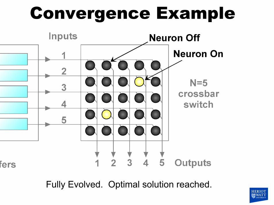
Convergence Example
Start state – all requested neurons are on.

Convergence Example
1/3 Evolved: Neurons (2, 4) and (4, 2) are beginning to inhibiting neuron (2, 2).

Convergence Example
2/3 Evolved: Neuron (2, 2) is nearly off.
Convergence Example
Fully Evolved. Optimal solution reached.

Neural Interconnect

Neural AlgorithmNext state defined by:
� � � ���
�
�
��
�
������ ��
��2CyByAt1txtx
n
ikkj
n
jkikijij
xij: Summation of all the inputs to the neuron referenced by ij: including the bias.
yij: Output of neuron ij.
A, B and C: Optimisation parameters.
� �ijxijij e1
1xfy��
�
�� �: Controls gain of neuron.
Neural transfer function:
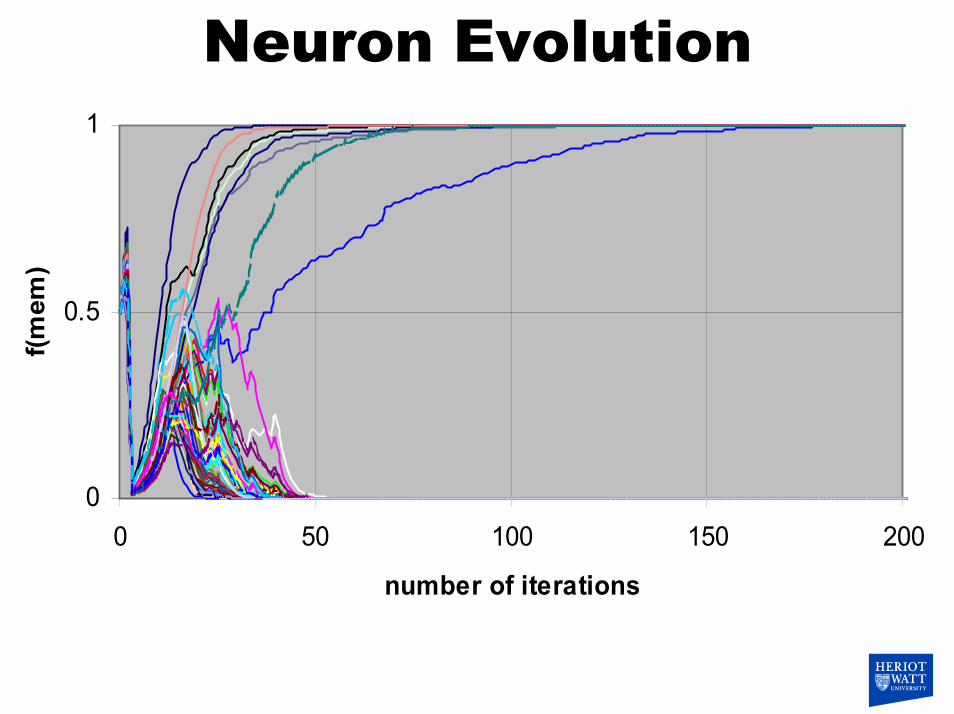
Neuron Evolution
0
0.5
1
0 50 100 150 200
number of iterations
f(mem
)

• Neural network scalability limited in silicon.
• Free-space optics can be used to perform interconnection.
• Only transfer function f(x) need be performed in silicon.
• Input summation is done in an inherently analogue manner.
• Noise added naturally.
Why Optoelectronics?

Crossbar switch interconnect.Banyan switch interconnect.
Optical Interconnect
DOE interconnect is space invariant.

Current System
Characteristics
• System uses 4×40MHz Texas Instruments 320C5x DSPs.
• DSPs perform transfer function.
• Transfer function fully programmable.
• Balance of analogue and digital hybridisation can be adjusted.

Actual System
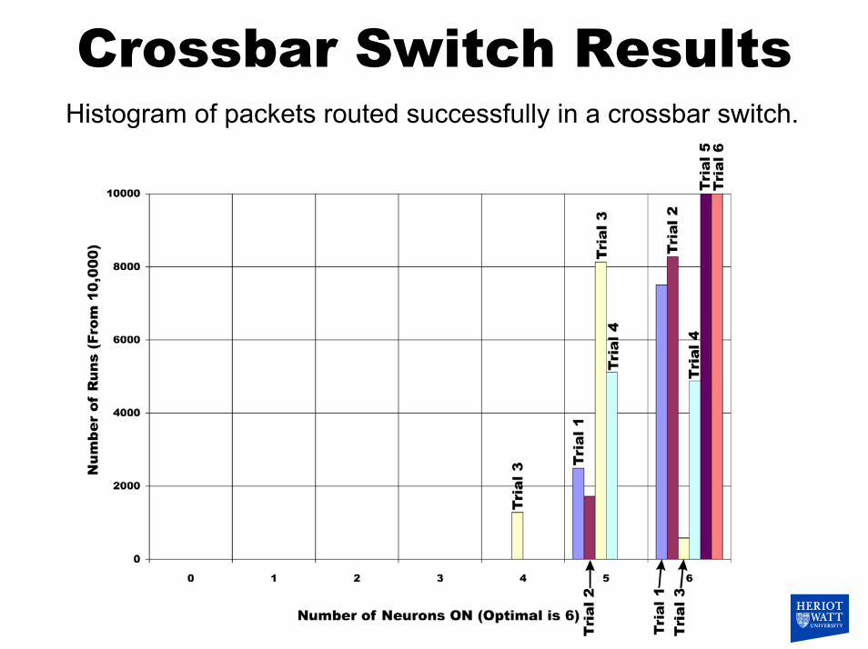
Crossbar Switch ResultsHistogram of packets routed successfully in a crossbar switch.
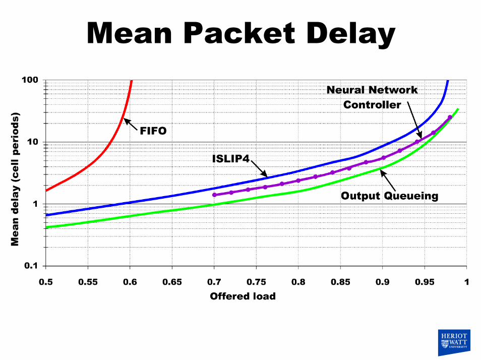
Mean Packet Delay

System Scalability

Digital vs. Analogue
Analogue: Optimal ~97%. Digital: Optimal ~91%.

Crossbar Switch Validity
0.95
1.1 1.
25
13
15
17
19
0
20
40
60
80
100
validity (%)
AB
80-100
60-80
40-60
20-40
0-20

Crossbar Switch Optimality
0.95 1.
05 1.15 1.
25
13
15
17
19
66.26.46.66.877.27.47.67.88
average number of neurons on
AB
7.8-8
7.6-7.8
7.4-7.6
7.2-7.4
7-7.2
6.8-7
6.6-6.8
6.4-6.6
6.2-6.4
6-6.2

Control loop optimisationControl system currently operated in software with test sets
Parameters A,B and C/2 can be adjusted to find point of maximum optimality within the valid region.
Control system also used for calibration, fault tolerance and diagnostics (e.g. alignment, finger prints on DOE etc.)

General Purpose Operation
• Algorithms can be changed by changing DOE elements.
• King, Queen and Knight problems performed• Noise removal and labelling• Correlation, FFT• General purpose digital or analogue machine (but not
necessarily efficient unless mapping is good).• Some algorithms require complex synchronisation of
steps and “superiterations”• Use of adaptive optics/weights possible.
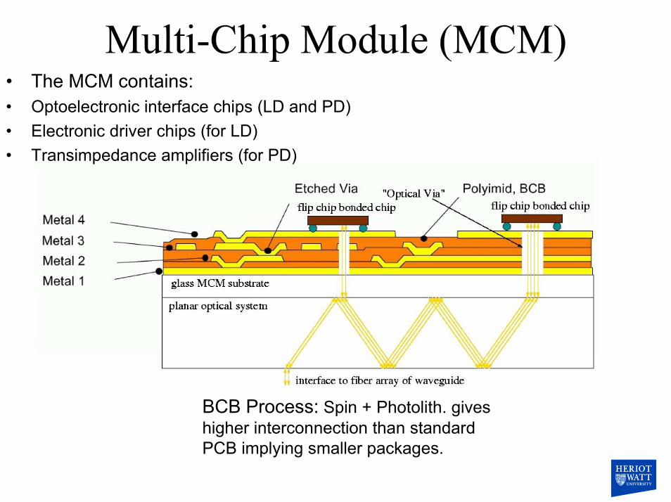
• The MCM contains:• Optoelectronic interface chips (LD and PD)• Electronic driver chips (for LD)• Transimpedance amplifiers (for PD)
BCB Process: Spin + Photolith. gives higher interconnection than standard PCB implying smaller packages.

Conclusions 1• System works completely and delivers good solutions
• Performance of 1GHz and higher feasible.• A digital system running at 1GHz could supply 2.5 million
switch configurations per second.
• Scalability mainly limited by VCSEL array size (N=8) -system copes well with noise and poor SNR.
• Scalability independent of number of inputs/outputs (N).
Conclusions 2• Very simple -fixed identical weights.• Simplicity implies very high performance can be reached.• Can be general purpose machine - several algorithms run.
• It really does work.
• Further work: Packaging and integration (maybe HOLMS MCM solution), customised electronics/FPGA? Adaptive optics/weights.


