Page 1
21st International Conference on Composite Materials
Xi’an, 20-25th August 2017
A NEW DESIGN OF END-TAB FOR THE TENSILE TESTING OF
UNIDIRECTIONAL THERMOPLASTIC COMPOSITES CF/PA6
Mazlina Mohd Tahir1,2, Wen-Xue Wang3 and Terutake Matsubara 3
1 Department of Aeronautics and Astronautics, Engineering School, Kyushu University, Motooka
Nishi-ku Fukuoka 819-0395, Japan, [email protected] 2 Department of Polytechnic Educational, W.P Putrajaya 62100, Malaysia
3 Research Institute for Applied Mechanics, Kyushu University, Kasuga, Fukuoka 816-8580, Japan,
[email protected] and [email protected]
Keywords: UD laminate, Tensile testing, End-tab design, Thermoplastic composites
ABSTRACT
This study proposes a new design of end-tab for the tensile testing of unidirectional (UD) carbon
fiber reinforced thermoplastic polyamide-6 (CF/PA6) to reduce stress concentration at the tab end. The
new tab has the same length as the UD CF/PA6 specimen to avoid the sudden change of geometry as
seen in conventional tabbed specimens. Three kinds of UD CF/PA6 materials made from different
manufacturers are used for the fabrication of tensile specimens. Specimens with new tab and
conventional non-tapered tab are tested, respectively. Finite element simulations of tensile testing for
UD specimens with new and conventional tabs are carried out. Experimental and simulation results
demonstrate that the new tab design can reduce the stress concentration near the tab end by about 10%
and improve the estimation of tensile strength of UD thermoplastic composite laminates.
1 INTRODUCTION
One of the most basic mechanical properties of continuous fiber reinforced composite materials is
the ultimate tensile strength of unidirectional (UD) composite materials in the fiber direction.
Therefore, reasonable measurement of tensile strength of UD composite materials in the fiber direction
is important for the design and application of composite materials. In the cases of conventional
homogeneous and isotropic materials, such as various metals and plastics, specimens for tensile testing
can be easily machined into dog-bone or hourglass geometries and be expected to fail in the waist
section of the specimen. However, in the case of continuous fiber reinforced composite materials, it is
difficult to machine a specimen of unidirectional composite laminate into a dog-bone or hourglass
shape because machining UD specimen into waist shape causes a discontinuity of fibers in the
specimen from the wide clamp region to the waist region. In addition, machining composite materials
easily induces various damages near the machined surface, which may reduce the tensile strength of
the specimen. High cost of machining a shaped specimen of composite materials is also a drawback.
For these reasons, various national and international standards [1-5] recommend flat and straight-side
specimen geometries with end tabs to prevent clamp failure. However, in tabbed specimens, there are
high stress concentrations near the tab end due to the sudden changes in geometry, in material, and in
the transmission of force from the shear and gripping pressure between tab and specimen to tension in
the specimen. High stress concentrations around the tab end cause the specimen failure near the tab
end and lead to an underestimation of tensile strength of UD composite specimen.
A few efforts [6-11] have been made to investigate the effects of tab shape and tab material on the
tensile testing results of UD composite laminates. Analysis of stress distribution in [6, 7] indicated that
stress concentration at the root of the non-tapered tab is much high than that at tapered tab. On the
other hand, Hojo et al. [8] experimentally investigated the effects of non-tapered tab and 10° tapered
tab on the tensile strength of UD carbon fiber reinforced (thermosetting) plastics (CFRP). Their
experimental results showed a small difference (3% to 4%) in the tensile strength in the fiber direction
of two types of tabbed specimens. Most specimens failed near the tab ends and inside tabs. 60% to
85% specimens with tapered tab broke inside the tab within the region between the tapered and non-
tapered parts and 20% to 55% specimen with straight tab broke slightly inside the tab. High shear
Page 2
Mazlina Mohd Tahir, Wen-Xue Wang. Author and Terutake Matsubara
stress and low shear strength in the tapered region between the tapered tab and the specimen easily
produce a delamination between the tapered part of the tab and the specimen. The delamination
significantly deletes the effectiveness of tapered part in the reduction of stress concentration at the tab
end. Maheri [9] and Wisnom et al. [10] developed a waist specimen through the thickness using a
drop-ply layup technique. Improvement of 9.4% to 13.7% in tensile strength was reported in [9]
compared to flat specimen through the thickness. However, the fabrication of this kind of waist
specimen is not cost effective. Baere et al. [11] investigated the effects of tab shape and tab layup on
the tensile strength of [(0, 90)]4s carbon fiber reinforced PPS (Poly Phenylene Sulfide) numerically
and experimentally. Here, PPS is a kind of thermoplastic resin and (0, 90) represents one layer of
fabric of 5-harness satin weave. In their numerical results, tapered tab gives lower stress concentration
at the tab end than non-tapered tab. However, due to that the chemical inertness of the PPS results a
poor bond between tab and specimen, authors proposed to use non-tapered tab for specimen of carbon
fiber reinforced thermoplastic (CFRTP). Thus, it is more difficult to expect the effectiveness of
tapered tab in the reduction of stress concentration at the clamping end of CFRTP specimens,
compared to thermosetting resin based composite specimens. Therefore, designing a cost-effective tab
for the tensile testing of unidirectional thermoplastic composite materials is still a hard challenge due
to the trade-off of specimen fabrication cost and the acceptable experimental results.
This study proposes a new design of aluminum tab for the tensile testing of UD carbon fiber
reinforced thermoplastic polyamide-6 (CF/PA6) to reduce stress concentration at the tab end. The new
tab aluminum has the same length as the UD CF/PA6 specimen to avoid the sudden change of
geometry as seen in conventional tabbed specimens. Three kinds of UD CF/PA6 laminates made from
different manufacturers are used for the fabrication of tensile specimens. Specimens with new
designed tab and conventional non-tapered tab are tested, respectively. Numerical simulations for UD
specimens with new and conventional tabs are carried out. The cost-effectiveness of the new tab
design is examined based on numerical and experimental results.
2 EXPERIMENTAL DETAILS
Experimental details are described in the following two subsections.
2.1 Materials and specimens
Three types of UD CF/PA6 laminates made from three different manufacturers of CF/PA6 tapes
are used to demonstrate the validity of new designed tab for the tensile testing of UD CF/PA6
laminates. First one is AFPT UD CF/PA6 laminate [0°]8 which is made from Celstran® CFR-TP PA6
tape and fabricated by AFPT GmBH (Germany) using laser assisted thermoplastic fiber placement
technology. The nominal thickness of AFPT laminate thickness is 1.2 mm. The process temperature is
250 ℃, tape speed is 9 mm/min, cooling temperature is 100℃, and consolidation pressure is 0.2 MPa.
The second one is Maruhachi UD CF/PA6 laminate [0°]8 which is made from spread tow carbon fiber
reinforced PA6 8exe®-U prepregs and fabricated by Maruhachi Cooperation (Japan) using hot
pressing technology. The nominal thickness of Maruhachi laminate is 1.4 mm. The process
temperature is 235 ℃ and the consolidation pressure is 3 MPa. The third one is TenCate CF/PA6
laminate [0°]8 which is made from TenCate Cetex®-TC910 CF/PA6 tape and fabricated by Maruhachi
Cooperation (Japan) using hot pressing technology. The nominal thickness of TenCate laminate is 1.2
mm. The process conditions are as same as those used in the fabrication of the second one. Aluminum
alloy 2024-T3 plate of 1 mm thickness is used to make the tabs since the aluminum alloy plate is
easily machined into any shape compared to carbon fiber reinforced plastics.
Specimen of 20×250×thickness (mm3) is cut from the UD CF/PA6 laminates using a water cooled
diamond cutter and is designed basically following the national standards of ASTM D 3039/D 3039M
and JIS K7073 with a gauge length of 150 mm. The specimen is 5 mm wider than the recommended
specimen width in the standards because the new tab has a long central hole with 6 mm width for
bonding the strain gauge on the specimen to measure a tensile strain. Dimensions of tabbed specimens
with two types of tabs are showed in Figure 1 and Figure 2, respectively. Conventional non-tapered
tab, as shown in Figure 1, is a rectangular tab of 20×50×1 (mm3). The new tab is depicted
Page 3
21st International Conference on Composite Materials
Xi’an, 20-25th August 2017
Figure 1: Dimensions of specimen with conventional non-tapered aluminum tab.
Figure 2: Dimensions of specimen with newly designed aluminum tab.
Figure 3: Images of typical tabbed specimens with different tabs.
in Figure 2. It has the same length as the CF/PA6 specimen to reduce the stress concentration at the tab
end due to the sudden change of geometry as seen in conventional tabbed specimens. A long hole at
the central area of the tab is made to measure the tensile strain at the center of CF/PA6 specimen. Tabs
are bonded to the two surfaces of specimens using 2-Ethyl cyanoacrylate adhesive CC-33A (Kyowa
Page 4
Mazlina Mohd Tahir, Wen-Xue Wang. Author and Terutake Matsubara
Electronic Instruments Co., LTD.). The bonding length between specimen surface and the tab is 50
mm at both ends of the specimen and a thin Kapton film is inserted at the gauge length between
CF/PA6 specimen and the new tab to prevent the adhesive from adhering throughout the gauge length.
Typical tabbed specimens are shown in Figure 3. One strain gauge is bonded to the central surface of
the tabbed CF/PA6 specimens. In the case of specimen with new tab, one more strain gauge is bonded
to the central surface of aluminum tab to measure the tensile strain of aluminum tab. According to the
limitation of composite laminates, three specimens for each type of tabbed specimens of AFPT
laminate and Maruhachi laminate, and six specimens for each type of tabbed specimens of TenCate
laminate are fabricated, respectively.
2.2 Tensile testing
Tensile tests of tabbed specimens are carried out using MTS 810 servo-hydraulic material testing
system at a constant crosshead speed 1 mm/min. The testing machine is operated using a personal
computer and a TestStar digital controller system. All tests are conducted under ambient conditions.
Each specimen is clamped by using hydraulic wedge grips. Clamping length is about 50 mm and
clamping pressure is set to 10 MPa. Tensile load and tensile strain occurred in the specimen are
recorded. In addition, three specimens of aluminum alloy plate that is used to make tabs are also
tested under tension to measure the elastoplastic stress-strain curve.
Tensile stress at the center of CF/PA6 specimen with conventional tab is calculated by
CFRTPCFRTP AF / (1)
Where F is the tensile load applied on the specimen and ACFRTP is the crass-section area at the center of
the CF/PA6 specimen. In the case of specimen with new tab, the tensile stress at the center of CF/PA6
specimen is calculated by
CFRTPAlAlCFRTP AAF /)( (2)
Where F is the tensile load applied on the specimen including aluminum tab, is the total crass-
section area of aluminum tab at the center, and is the stress occurred in the central parts of
aluminum tab and is calculated by the use of stress-strain curve obtained from the tensile test of
aluminum plate. Tensile strength of the CF/PA6 specimen is defined by the tensile stress at the
maximum tensile load. Tensile modulus of the CF/PA6 specimen is calculated from the chord
modulus of its stress-strain curve between 0.1% and 0.4 % strain levels [8] since the carbon fiber is
nonlinear elastic and the tensile modulus of the fiber increases with the increase of applied tensile
strain due to the re-orientation of graphite crystal in the fiber [12-14]. The fiber volume fraction for
each kinds of CF/PA6 laminates are evaluated based on the measured tensile modulus and the mixture
law.
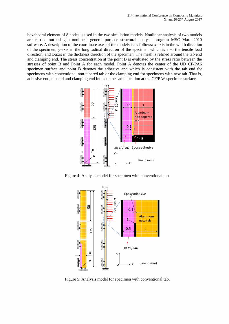
3 FINITE ELEMENT ANALYSIS
In addition to experimental, finite element (FE) simulations of tensile testing of UD CF/PA6
specimens with different tabs are also conducted to investigate the difference in the stress
concentration at the tab end or clamping end for two kinds of tabbed specimens. Geometries and
boundary conditions of two analysis models for specimens with conventional tab and with new tab are
described in Figure 4 and Figure 5, respectively.
According to the symmetry of the tabbed specimens, only 1/8 of the specimen was modeled for two
kinds of tabbed specimens. The adhesive layer between the tab and the specimen was modeled by a
thin resin layer of 0.1 mm thickness. The loading conditions applied on the tab surface are designated
by the horizontal and vertical arrows. The horizontal arrows represent the uniform clamping pressure
of 10 MPa and the vertical arrows indicate the applied uniform tensile displacement of 1.25 mm. The
UD CF/PA6 is considered as elastic and orthotropic laminate. The material constants of UD CF/PA6
used in the present simulation are listed in Table 1. Aluminum tab is considered as isotropic and
elastoplastic. The Young’s modulus is 70GPa, the Poisson’s ratio is 0.3, and the yield stress is 360
MPa. The elastoplastic stress-strain curve measured by the tensile testing of aluminum specimens is
used to simulate the elastoplastic deformation of aluminum tab. The adhesive layer is modeled as
isotropic and elastic material. The Young’s modulus is 3GPa, and its Poisson’s ratio is 0.42. The
Page 5
21st International Conference on Composite Materials
Xi’an, 20-25th August 2017
hexahedral element of 8 nodes is used in the two simulation models. Nonlinear analysis of two models
are carried out using a nonlinear general purpose structural analysis program MSC Marc 2010
software. A description of the coordinate axes of the models is as follows: x-axis in the width direction
of the specimen; y-axis in the longitudinal direction of the specimen which is also the tensile load
direction; and z-axis in the thickness direction of the specimen. The mesh is refined around the tab end
and clamping end. The stress concentration at the point B is evaluated by the stress ratio between the
stresses of point B and Point A for each model. Point A denotes the center of the UD CF/PA6
specimen surface and point B denotes the adhesive end which is consistent with the tab end for
specimens with conventional non-tapered tab or the clamping end for specimens with new tab. That is,
adhesive end, tab end and clamping end indicate the same location at the CF/PA6 specimen surface.
Figure 4: Analysis model for specimen with conventional tab.
Figure 5: Analysis model for specimen with conventional tab.
Page 6
Mazlina Mohd Tahir, Wen-Xue Wang. Author and Terutake Matsubara
Table 1: Material constants used in finite element analysis.
4 RESULTS AND DISCUSSIONS
Experimental and numerical analysis results are described in the following two subsections.
4.1 Experimental results
Microscopic images of three UD CF/PA6 laminates are presented in Figure 6: Images 6a and 6ba
are for AFPT laminate; Images 6c and 6d are for TenCate laminate, and Images 6e and 6f are for
Maruhachi laminate, respectively. In images 6a, 6c and 6e, the upper and lower photographs show the
polished surfaces normal to fibers and parallel to fibers, respectively. Enlarged images normal to fibers
are shown in 6b, 6d, and 6f for three UD CF/PA6 laminates, respectively. Layer-like fiber distribution
in AFPT laminate, bundle-like fiber distribution in TenCate laminate, and spread bundle-like fiber
distribution in Maruhachi laminate are observed. Different from nearly uniform fiber distribution in
conventional aircraft-grade UD CFRP laminas, present UD CF/PA6 laminas have non-uniform fiber
distribution. These non-uniform fiber distributions give a few influence on the testing results, as can be
seen late.
Figure 6: Microscopic images of three UD CF/PA6 laminates.
Stress-strain curves of three aluminum alloy specimens are described in Fig. 7 and very good
reproducibility is seen. For the simplicity, the stress-strain curve of aluminum alloy is described by a
bilinear curve expressed by following equations.
Page 7
21st International Conference on Composite Materials
Xi’an, 20-25th August 2017
,00525.0,70300 AlAlAl (3a)
00525.0,6.16737.358 AlAlAl (3b)
Where, the unit of stress is MPa. Then, the stress occurred at the center of the new tab can be easily
calculated using above equations.
Figure 7: Stress-strain curves of three aluminum alloy specimens.
Figure 8: Typical stress-strain curves of various UD CF/PA6 specimens under tension.
Typical stress-strain curves obtained from tensile testing of various CFRTP specimens are
described in Figure 8(a)-8(c), respectively, for three UD CF/PA6 laminates. Stresses are calculated
based on tensile load and Equation (1) for specimens with convention tab, Eq. (2) and Eqs. (3a) and
(3b) for specimens with new tab, respectively. It is obvious that higher tensile strength values and
higher failure strains are measured in the specimens with new tab than those measured in the
specimens with conventional tab. Results of tensile tests for various specimens are listed in Table 2.
AFPT laminate with new tab shows about 9% higher tensile strength, Maruhachi and TenCate
laminates with new tab show about 10% higher tensile strength, respectively, compared to the relative
specimens with conventional tab. These results demonstrate that the new tab is effective to obtain
Page 8
Mazlina Mohd Tahir, Wen-Xue Wang. Author and Terutake Matsubara
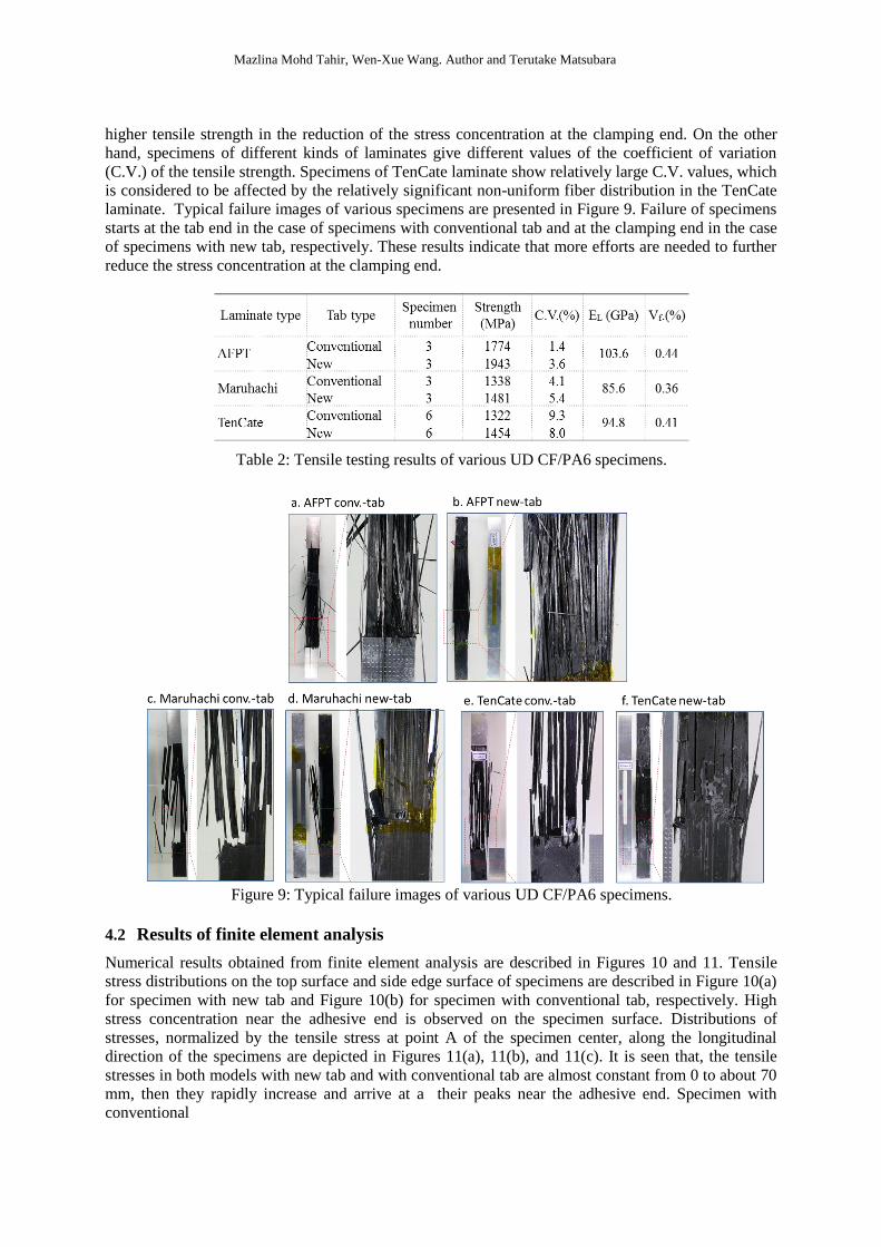
higher tensile strength in the reduction of the stress concentration at the clamping end. On the other
hand, specimens of different kinds of laminates give different values of the coefficient of variation
(C.V.) of the tensile strength. Specimens of TenCate laminate show relatively large C.V. values, which
is considered to be affected by the relatively significant non-uniform fiber distribution in the TenCate
laminate. Typical failure images of various specimens are presented in Figure 9. Failure of specimens
starts at the tab end in the case of specimens with conventional tab and at the clamping end in the case
of specimens with new tab, respectively. These results indicate that more efforts are needed to further
reduce the stress concentration at the clamping end.
Table 2: Tensile testing results of various UD CF/PA6 specimens.
Figure 9: Typical failure images of various UD CF/PA6 specimens.
4.2 Results of finite element analysis
Numerical results obtained from finite element analysis are described in Figures 10 and 11. Tensile
stress distributions on the top surface and side edge surface of specimens are described in Figure 10(a)
for specimen with new tab and Figure 10(b) for specimen with conventional tab, respectively. High
stress concentration near the adhesive end is observed on the specimen surface. Distributions of
stresses, normalized by the tensile stress at point A of the specimen center, along the longitudinal
direction of the specimens are depicted in Figures 11(a), 11(b), and 11(c). It is seen that, the tensile
stresses in both models with new tab and with conventional tab are almost constant from 0 to about 70
mm, then they rapidly increase and arrive at a their peaks near the adhesive end. Specimen with
conventional
Page 9
21st International Conference on Composite Materials
Xi’an, 20-25th August 2017
Figure 10: Tensile stress distributions on the top surface and side edge surface of specimens with
conventional tab and new tab.
Figure 11: Distributions of stresses along the longitudinal direction of the specimens, normalized by
the tensile stress at point A of the specimen center.
tab shows nearly 11% higher peak value of normalized tensile stress than that of specimen with new
tab. These analysis results are basically consistent with tensile testing results. Hence, it is indeed
available to use new tab for the reduction in the stress concentration at the adhesive end. Peeling stress
and interlaminar shear stress between the tab and the specimen are described in Figure 11(c).
Both kinds of specimens show similar stress distributions and the difference in their peak values is
negligible. It is noted that the values of these stress are taken from the values averaged at the nodes on
the model surface. Thus, these values are not the exact values of stresses on the surface and some
values of stresses below the surface are used in the calculation of averaged values at the nodes. That is
why these values are not zero before 75 mm. In spite of this approximation, quite high peeling stress
and interlaminar shear stress can be observed near the adhesive end. These stresses easily cause the
delamination between the tab and the specimen if the clamping end does not cover the adhesive end
because the adhesive strength between the tab and the CFRTP specimen is very low compared to the
tensile strength of the specimen.
Page 10
Mazlina Mohd Tahir, Wen-Xue Wang. Author and Terutake Matsubara
5 CONCLUSIONS
A new tab for the tensile tests of unidirectional CFRTP composites is proposed in this study to
reduce the stress concentration at the tab end. Tensile testing and finite element simulation for CFRTP
specimens with conventional tab and new tab are conducted. Based on the present experimental and
numerical analysis results, it is concluded that the new tab can reduce the stress concentration by
nearly 10% near the tab end. Thus, the new tab provides a cost-effective way to improve the
estimation of tensile strength in tensile testing of unidirectional CFRTP laminates. However, more
efforts are needed to further reduce the stress concentration.
ACKNOWLEDGEMENTS
Authors would like to thank Mr. Kenzou Yasuda and Mr. Hiroshi Kushiku from NHK Spring Co.,
Ltd. for providing the thermoplastic composite laminates in this research.
REFERENCES
[1] ASTM Standard D 3039/D 3039M-00. 2000. “Standard Test Method for Tensile Properties of
Polymer Matrix Composite Materials,” American Society for Testing and Materials, West
Conshohocken, PA.
[2] JIS K7073. 1988. “Testing method for tensile properties of carbon fiber reinforced plastics,”
Japan Industrial Standard.
[3] BS EN 2561. 1995. “Aerospace series - Carbon fibre reinforced plastics - Unidirectional
laminates - Tensile test parallel to the fibre direction,” British-Adopted European Standard.
[4] ISO 527-1 (2nd edition). 2012. “Plastics - Determination of tensile properties - Part 1 General
principles,” International organization for standardization.
[5] ISO 527-5. 1997. “Plastics - Determination of tensile properties - Part 5: Test conditions for
unidirectional fibre-reinforced plastic composites,” International organization for
standardization.
[6] Cunningham, M.E., Schoultz, S.V. and Toth, J.M. Jr. 1985. “Effect of End-Tab Design on
Tension Specimens Stress Concentrations”, Recent advances in Composites in the United States
and Japan, ASTM STP 864, pp. 253-262.
[7] Lévesque, M., Gilchrist, M. D., and Fisa, B. 2003. “A Theoretical Study of the Tensile Test for
Highly Anisotropic Composite Materials,” Composite Materials: Testing and Design
Fourteenth Volume, ASTM STP 1436, pp. 320-335.
[8] Hojo, M., Sawada, Y., and Miyairi, H. 1994. “Influence of clamping method on tensile
properties of unidirectional CFRP in 0° and 90° - round robin activity for international
standardization in Japan,” Composites, 25(8):786-796.
[9] Maheri, M.R.. 1995. “An improved method for testing unidirectional FRP composites in
tension” Composite Structures 33:27-34.
[10] Wisnom, M.R., Jones, M.I., and Cui W. 1995. “Failure of Tapered Composites Under Static and
Fatigue Tension Loading,” AIAA Journal, 33(5):911-918.
[11] I. De Baere, I.D., Paepegem, W.V., and Degrieck, J. 2009. “On the design of end tabs for
quasi-static and fatigue testing of fibre-reinforced composites,” Polymer Composites, 30(4):
381-390.
[12] G.J. Curtis, J.M. Milne, W.N. Reynolds, Non-hookean behavior of strong carbon fibres, Nature,
220 (1968), 1024-1025.
[13] T. Ishikawa, M. Matsushima, Y. Hayashi, Hardening non-linear behavior in longitudinal tension
of unidirectional carbon composites, Journal of Materials Science, 20 (1985), 4075-4083.
[14] M. Shioya, E. Hyakawa, A. Takaku, Non-hookean stress-strain response and changes in
crystallite orientation of carbon fibres, Journal of Materials Science 31 (1996), 4521-4532.