A new finite element for transverse vibration of rectangular thin plates under a moving mass _ Ismail Esen n Department of Mechanical Engineering, Karab¨ uk University, BalıklarKayasıMevkii, Karab¨ uk 78050, Turkey article info Article history: Received 6 April 2012 Received in revised form 9 November 2012 Accepted 13 November 2012 Available online 13 December 2012 Keywords: Finite element Plate vibrations Moving mass Moving force abstract In this paper a new finite element which can be used in the analysis of transverse vibrations of the plates under a moving point mass is presented. In this technique, which allows for the inclusion of inertial effects of the moving mass, the load is replaced with an equivalent finite element. By means of using the relations between nodal forces and nodal deflections of 16 DOF conforming plate element with C (1) continuity, on the one hand, and shape functions, on the other hand, mass, stiffness, and damping matrices of the new finite element are determined by the transverse inertia force, Coriolis force and centrifuge force, respectively. This method was first applied on a simply supported beam so as to provide a comparison with the previous studies in the literature, and it was proved that the results were within acceptable limits. Second, it was applied on a cantilevered plate so as to determine the dynamic response of the planer entry plate of a high-speed wood-cutting machine. & 2012 Elsevier B.V. All rights reserved. 1. Introduction Dynamic response of the structures under moving loads is a critical problem in engineering and has been studied by several researchers. Analysis of the dynamic response of a plate structure has also been an important area of interest for many designers. Fryba [1], as a perfect reference for simple situations with several analytical solution methods, conducted one of the first and most comprehensive studies on the moving load problem. In order to obtain the dynamic response of graded-thickness rectangular plates under moving loads, Takabataka [2] considered the con- tinuous change of bending stiffness and suggested an analytical method which used a characteristic function. Ghafoori and Asghari [3] studied the dynamic analysis of a laminated compo- site plate overrun by a moving mass depending on a first-order theory. Using finite element method, Shadnam et al. [4] studied this problem for isotropic plates. Wu et al. [5] and Yoshida and Weaver [6] analysed the dynamic response of plates subjected to various types of moving loads. Wu [7] attempted to find the equal beam models of a plate whose transverse directions are supported and longitudinal directions are free. Based on modified general- ized finite integral transformations and modified Strubles method, Gbadeyan and Oni [8] obtained some analytical results for the dynamic response of rectangular plates transversed by moving loads. Renard et al. [9] studied the dimensionless deflections and tensions of beams and plates under constant moving forces. They provided some asymptotic results of tran- sient deflections and stresses depending on the velocity and arrival time of the force. Esen [10] suggested a solution method that uses new finite element for the dynamic response of a beam under an accelerating moving mass. Esen et al. [11–13] studied the dynamic response of overhead crane beams under moving trolley using analytical and finite element methods. Monographic books and studies for structural and plate dynamics can be found in references [14–23]. Ahmadian et al. [24] studied the dynamic behavior of a laminated composite beam (LCB) supported by a generalized Pasternak-type viscoelastic foundation, subjected to a moving two-degree-of-freedom (DOFs) oscillator with a constant axial velocity, and they used the Galerkin method for the analytical solution. Sharbati and Szyszkowski [25,26] studied the dynamics of beam–moving mass systems and a ‘composite’ beam element was introduced, which explicitly identifies the Coriolis and centripetal effects dependent on the given current relative velocity of the particular mass. Lee, [27] investigated the onset of the separation between the moving mass and beam, and then took into account its effect in calculating the interaction forces and also in calculating the dynamic responses of the beams. He reported that the effects of separation become significant as the velocity of the moving mass and the mass ratio (mass of moving load/mass of structure) increase. Taking into consideration the inertial effects of the mass, moving load problem becomes even more complicated and studies in this area are limited. This paper offers a method of solution which accepts moving mass as a new finite element. Contents lists available at SciVerse ScienceDirect journal homepage: www.elsevier.com/locate/finel Finite Elements in Analysis and Design 0168-874X/$ - see front matter & 2012 Elsevier B.V. All rights reserved. http://dx.doi.org/10.1016/j.finel.2012.11.005 n Tel.: þ905053777046. E-mail address: [email protected]Finite Elements in Analysis and Design 66 (2013) 26–35
Transcript
Finite Elements in Analysis and Design 66 (2013) 26–35
Contents lists available at SciVerse ScienceDirect
Finite Elements in Analysis and Design
0168-87
http://d
n Tel.:
E-m
journal homepage: www.elsevier.com/locate/finel
A new finite element for transverse vibration of rectangular thin plates undera moving mass
_Ismail Esen n
Department of Mechanical Engineering, Karabuk University, BalıklarKayasıMevkii, Karabuk 78050, Turkey
a r t i c l e i n f o
Article history:
Received 6 April 2012
Received in revised form
9 November 2012
Accepted 13 November 2012Available online 13 December 2012
In this paper a new finite element which can be used in the analysis of transverse vibrations of the
plates under a moving point mass is presented. In this technique, which allows for the inclusion of
inertial effects of the moving mass, the load is replaced with an equivalent finite element. By means of
using the relations between nodal forces and nodal deflections of 16 DOF conforming plate element
with C(1) continuity, on the one hand, and shape functions, on the other hand, mass, stiffness, and
damping matrices of the new finite element are determined by the transverse inertia force, Coriolis
force and centrifuge force, respectively. This method was first applied on a simply supported beam so as
to provide a comparison with the previous studies in the literature, and it was proved that the results
were within acceptable limits. Second, it was applied on a cantilevered plate so as to determine the
dynamic response of the planer entry plate of a high-speed wood-cutting machine.
& 2012 Elsevier B.V. All rights reserved.
1. Introduction
Dynamic response of the structures under moving loads is acritical problem in engineering and has been studied by severalresearchers. Analysis of the dynamic response of a plate structurehas also been an important area of interest for many designers.Fryba [1], as a perfect reference for simple situations with severalanalytical solution methods, conducted one of the first and mostcomprehensive studies on the moving load problem. In order toobtain the dynamic response of graded-thickness rectangularplates under moving loads, Takabataka [2] considered the con-tinuous change of bending stiffness and suggested an analyticalmethod which used a characteristic function. Ghafoori andAsghari [3] studied the dynamic analysis of a laminated compo-site plate overrun by a moving mass depending on a first-ordertheory. Using finite element method, Shadnam et al. [4] studiedthis problem for isotropic plates. Wu et al. [5] and Yoshida andWeaver [6] analysed the dynamic response of plates subjected tovarious types of moving loads. Wu [7] attempted to find the equalbeam models of a plate whose transverse directions are supportedand longitudinal directions are free. Based on modified general-ized finite integral transformations and modified Strublesmethod, Gbadeyan and Oni [8] obtained some analytical resultsfor the dynamic response of rectangular plates transversed bymoving loads. Renard et al. [9] studied the dimensionless
All rights reserved.
deflections and tensions of beams and plates under constantmoving forces. They provided some asymptotic results of tran-sient deflections and stresses depending on the velocity andarrival time of the force. Esen [10] suggested a solution methodthat uses new finite element for the dynamic response of a beamunder an accelerating moving mass. Esen et al. [11–13] studiedthe dynamic response of overhead crane beams under movingtrolley using analytical and finite element methods. Monographicbooks and studies for structural and plate dynamics can be foundin references [14–23]. Ahmadian et al. [24] studied the dynamicbehavior of a laminated composite beam (LCB) supported by ageneralized Pasternak-type viscoelastic foundation, subjected to amoving two-degree-of-freedom (DOFs) oscillator with a constantaxial velocity, and they used the Galerkin method for theanalytical solution. Sharbati and Szyszkowski [25,26] studiedthe dynamics of beam–moving mass systems and a ‘composite’beam element was introduced, which explicitly identifies theCoriolis and centripetal effects dependent on the given currentrelative velocity of the particular mass. Lee, [27] investigated theonset of the separation between the moving mass and beam, andthen took into account its effect in calculating the interactionforces and also in calculating the dynamic responses of the beams.He reported that the effects of separation become significant asthe velocity of the moving mass and the mass ratio (mass ofmoving load/mass of structure) increase.
Taking into consideration the inertial effects of the mass,moving load problem becomes even more complicated andstudies in this area are limited. This paper offers a methodof solution which accepts moving mass as a new finite element.
Fig. 2. Equivalent node forces and node deflections of sth plate element onto
which moving mass m is applied at time t.
_I. Esen / Finite Elements in Analysis and Design 66 (2013) 26–35 27
The new finite element, representing the motion of a movingmass with all effects, is combined with the classical finite elementmethod. Analytical methods provided in the literature such asGbadeyan et al. [8] and Takabataka [2] can prove insufficient inthe solution of some complex-shaped plates under movingmasses. As suggested, the method in this study which can beapplied together with classical finite element method can beimplemented to plates with different geometries under all kindsof loading, boundary and damping conditions. With the suggestedmethod in this paper, one of recent important subjects that is thevehicle–structure interaction problem, can also be modelled andresults can be compared with the studies in the literature. Platesare structural elements which are widely used in machinemanufacturing as well as wood processing machines; theirdynamic behaviour has to be perfectly determined, so that somedesign and quality requirements can be met.
2. Mathematical modelling
Fig. 1 shows a rectangular plate, a moving lumped mass on it,and a finite element model, and the plate is divided into rectangularplate elements with the dimensions a and b. The plate has lx, lydimensions in the directions x and y with thickness h. The massmoves on the plate with a constant velocity v through a straightline which is at a distance e from the origin O as being parallel toaxis x. The thickness of the plate is low compared to otherdimensions; it was considered a Kirchhoff plate. The most impor-tant assumption of Kirchhoff plate theory is that the lines vertical tothe middle surface of the plate thickness are vertical and straight tothe deformed middle surface even after deformation. This theoryignores the deformations caused by share. In this study it isaccepted that deflections are small, and within Hook’s law andother assumptions of the Kirchhoff plate theory provided by [14]are valid. Accordingly, in the case that the system is an isotropicplate and there is no damping in the plate and loading system, thedifferential equation of the motion of the plate is [1,14]:
D@4w
@x4þ2
@4w
@x2@y2þ@4w
@y4
" #þm @
2w
@t2¼ p x,y,tð Þ, ð1Þ
where D¼Eh3/12(1�u2) is the flexural rigidity and E, m and u areYoung’s modulus of elasticity, mass per unit area and Poisson’sratio, respectively. While h is the constant thickness of the plate.
2.1. Finite element model of a moving mass on a plate
Fig. 2 shows the four-nodal rectangular sth plate element onwhich the moving mass m applies at time t as well as the nodalforces and deflections of this element. The mass moves with aconstant velocity v and a variable contact point Xm(t) with y axismeasure e. In this study it is assumed that the mass is in contactwith the plate during all travelling time. While the mass pro-gresses the plate vibrates, the interaction force is caused by
Fig. 1. A rectangular plate on which there is a moving lumped mass that moves
with a constant velocity vat distance e from the origin O as being parallel to axis x;
and finite element model that is divided into rectangular plate elements at
dimensions a and b.
gravity and the vibration acceleration of the plate; therefore, thetransverse (z) force component between the plate and movingmass induced by the curvature of the deformed plate and gravityis [14]:
f x,y,tð Þ ¼ mg�md2w Xm,Ym,tð Þ
dt2
" #d x�vtð Þd y�eð Þ, ð2Þ
where f(x, y, t) is the net force applied by the moving mass on x, y
points at time t. d x�vtð Þ and d y�eð Þ represent the Dirac deltafunctions in x and y directions, respectively. When the inertialeffect of the moving mass is taken into consideration, theacceleration d2w/dt2 is calculated from the second-order totaldifferential by accepting that x and y coordinates that determinethe motion of the load on the plate is a function of time. Theacceleration is obtained as follows when differential is takentwice according to the x and y variables.
In this equation Xm(t) and Ym(t) represent the overall x and y
coordinates of the mass on the plate, respectively. As there are novelocity components in y direction in this study, general Ym(t)term is constant and Ym(t)¼e. The derivation procedure of Eq. (3)is given in Appendix A. When Eq. (2) is rearranged according toEq. (3) the force equation is given by
where, � , signs show the derivatives of deflection depending ondimension and time.
Eq. (4) shows the general situation of the applied force. Ifmoving mass moves in x direction with a constant velocity andthere are no velocity components in y direction, €x and €y accel-eration terms and _y velocity term in y direction are equal to zero.In this case, Eq. (4) becomes
f x,y,tð Þ ¼ ½mg� mv2w00xþm €wþ2mv _w 0x� �
�d x�vtð Þd y�eð Þ, ð5Þ
where v shows the velocity of the moving mass and mv2w00x, m €w
and 2mv _w 0x show the centripetal force, inertia force and Coriolisforce components of the moving mass, respectively. Subscript ‘‘x’’shows that the deflection function is differentiated according to x.Eq. (5) is similar to the formulas given by Cifuentes [19] and Esen[10] for the beams under a moving mass. The reason for thissimilarity is the plate problem as two-dimensional situation ofthe beam. Nevertheless, as the shape functions of beam elementand plate elements are different from each other, Eq. (5) willyield different results for the beam element and plate element.
_I. Esen / Finite Elements in Analysis and Design 66 (2013) 26–3528
The rectangular plate element in Fig. 2 is a 16-DOF conformingplate element with C(1) continuity conditions at element bound-aries. It includes constant twist @2w/@x@y at corner nodes. Henceeach corner nodal displacement is [17]:
ui ¼ fui1 ui2 ui3 ui4gT ¼ fw yx yy yxyg
Ti
¼ w@w
@y�@w
@x
@2w
@x@y
( )T
i
i¼ 1, 2, 3, 4ð Þ, ð6Þ
where w is the vertical deflection of ith nodal point, and yxi, yyi
and yxyiare, respectively the rotation angles of ith nodal point
around axes x and y and twist at axes x and y. When thegravitational force and the inertia forces of the plate are takeninto consideration, the equivalent nodal forces of the sth plateelement are as given in Eq. (7) depending on the relevant shapefunctions.
f sn¼Nn½mg� mv2w00xþm €wþ2mv _w 0x
� �� n¼ 1, 2, 3,:::, 16ð Þ, ð7Þ
where Nn (n¼1, 2, 3, y, 16) are the shape functions of plateelement and given by [14].
N1 ¼ p1q1,
N2 ¼ p2q1,
N3 ¼ p1q2,
N4 ¼ p2q2,
N5 ¼ p1q3,
N6 ¼ p2q3,
N7 ¼ p1q4,
N8 ¼ p2q4,
N9 ¼ p3q3,
N10 ¼ p4q3,
N11 ¼ p3q4,
N12 ¼ p4q4,
N13 ¼ p3q1,
N14 ¼ p4q1,
N15 ¼ p3q2,
N16 ¼ p4q2,
ð8Þ
where pn and qn (n¼1–4) are hermitic polynomial componentsthat represent the shape functions of the plate at axes x and y,respectively.
p1 ¼ 1�3xðtÞ2þ2xðtÞ3,
p2 ¼ a½xðtÞ�2xðtÞ2þxðtÞ3�,p3 ¼ 3xðtÞ2�2xðtÞ3,
p4 ¼ a½xðtÞ3�xðtÞ2�,
q1 ¼ 1=b3½b3�3by2þ2y3�,
q2 ¼ 1=b2½b2y�2by2þy3�,
q3 ¼ 1=b3½3by2�2y3�,
q4 ¼ 1=b2½y3�by2�,
ð9aÞ
xðtÞ ¼ xmðtÞ=a,
y¼ ym ¼ Z¼ b=2,ð9bÞ
Here, as can be seen in Fig. 2, a and b are length and width ofsth plate element, respectively, whereas xm(t) is the distancebetween moving mass and the left end of sth plate element.ym¼Z is the constant distance between moving mass and axis x; itis assumed in this paper that this distance is on the line thatpasses through the middle point of the plate element. At any timet the relation between the deflection of any point at x and y
coordinates in plate element and shape functions is
w x,y,tð Þ ¼N1us1þN2us2
þN3us3þN4us4
þ � � � þN15us15þN16us16
,
ð10Þ
where usi (i¼1–16) is the deflections of nodes of the sth plateelement on which moving mass is located. The deflection equa-tion given in Eq. (10) is placed in the equivalent nodal forceequation of sth element given in Eq. (7); when the obtainedequations are organized in the form of a matrix, the followingmatrix equation is obtained:
ff g ¼ ½m�f €ugþ½c�f _ugþ½k�fug, ð11Þ
with,
ff g ¼ f s1f s2
f s3� � � f s16
h iT,
f €ug ¼ €us1€us2
€us3� � � €us16
h iT,
f _ug ¼ _us1_us2
_us3� � � _us16
h iT,
fug ¼ us1us2
us3� � � us16
h iT,
ð12aÞ
½m� ¼m
N12 N1N2 N1N3 � � � N1N16
N2N1 N22 N2N3 � � � N2N16
N3N1 N3N2 N32� � � N3N16
: : : � � � :
N16N1 N16N2 N16N3 � � � N162
26666664
37777775
,
½c� ¼ 2mv
N1N01 N1N02 N1N03 � � � N1N016
N2N01 N2N02 N2N03 � � � N2N016
N3N01 N3N02 N3N03 � � � N3N016
: : : � � � :
N16N01 N16N02 N16N03 � � � N16N016
26666664
37777775
,
½k� ¼mv2
N1N001 N1N002 N1N003 � � � N1N0016
N2N001 N2N002 N2N003 � � � N2N0016
N3N001 N3N002 N3N003 � � � N3N0016
: : : � � � :
N16N001 N16N002 N16N003 � � � N16N0016
26666664
37777775
, ð12bÞ
where [m], [c] and [k] are mass, damping and stiffness matrices ofthe new finite element, respectively. As the position of themoving mass changes by depending on time, the values of mass,damping and stiffness matrices, [m], [c] and [k], also change intime. Dimensions of these matrices of the new finite element arethe same as dimensions of mass, damping and stiffness matricesof the plate element, because the matrices of the new finiteelement are calculated from the equivalent nodal deflections andrelated shape functions of the plate element. As rectangular plateelement (see Fig. 2) has 4 deflections at each corner nodal point,the dimensions of the property matrices of the new finite elementwould be 16�16. The force vector (11) is calculated at each timestep according to xm(t) that is the instantaneous position of themoving mass on the element s. When moving mass travels atvariable speed (accelerating or decelerating), in this case theterms _w 0x €x and _w 0y €y in (11) do not vanish and the force vector(11) can be created with the contribution of these terms using theformulation given in Appendix C. For acceleration (þ), and fordeceleration (�) is used in Eq. (A.5).
3. Equation of the motion of the plate system under movingmass
Finite elements expression of the equation of the motion for asystem consisting of moving masses and plate is as follows.
½M�f€zðtÞgþ½C�f_zðtÞgþ½K�fzðtÞg ¼ fFðtÞg, ð13Þ
where ½M�, ½C� and ½K� are mass, damping and stiffness matrices ofthe entire system at time t, respectively; f€zðtÞg, f_zðtÞg and fzðtÞg arethe acceleration, velocity and deflection vectors of the system,respectively, and fFðtÞg is the external force vector of the system.
3.1. Overall stiffness and mass matrices of the structure
In cases where an additional load does not exist, overallstiffness K and mass M matrices of the plate system seen inFig. 1 can be obtained by combining Ke, Me element matrices of
_I. Esen / Finite Elements in Analysis and Design 66 (2013) 26–35 29
the plate and application of the given boundary conditions.Stiffness coefficients ke
ij of the element Ke matrix can be calculatedwith the following Equation [14]
keij ¼D
Z b
0
Z a
0
@2Ni
@x2
@2Nj
@x2þu
@2Ni
@x2
@2Nj
@y2þu
@2Nj
@x2
@2Ni
@y2
"
þ@2Ni
@y2
@2Nj
@y2þ2 1�uð Þ
@2Ni
@x@y
@2Nj
@x@y
#dx dy ð14Þ
meij coefficients of the Me kinematically consistent mass matrices are:
meij ¼ m
Z a
0
Z b
0Ni x,yð ÞNj x,yð Þ dx dy ð15Þ
where m is the mass of unit area of the plate, whereas a and b aredimensions of the plate in the directions x and y. When the movingmass exists, stiffness and mass matrices of the entire system can beobtained by taking into consideration the inertial and centripetalforces caused by moving mass. In this case, instant overall stiffnessand mass matrices are:
Kij ¼ Kij, Mij ¼Mij i,j¼ 1�n : total system DOFð Þ, ð16Þ
except for the coefficients of the sth plate element:
When the mass reaches sth element, we add the [m] and[k]matrices of the new finite element given in Eq. (12) to theelement mass and stiffness matrices of the sth plate element. Incalculating the instant values of [m], [k]and [c] time-dependentmatrices, it will be necessary to obtain equation x(t)¼xm(t)/a thatrepresents the position of the mass on sth element and toevaluate the shape functions according to this x(t) value andsubstitute it in Eq. (9); therefore, instant values of xm(t) and s aredetermined as follows
xmðtÞ ¼ vt� s�1ð Þlx
s¼ integer part of ½ elx=ba� �
þ vt=lx� �
�þ1,ð18Þ
3.2. Overall damping matrix of the structure
In order to investigate the effect of damping on the structure,damping matrix C can be obtained by using the Rayleigh dampingtheory which assumes that the damping matrix is proportionateto a combination of mass and stiffness matrix [15].
C ¼ a0Mþa1K ,
with,
a0
a1
( )¼ 2
oioj
oj2�oi
2
oj �oi
�1oj
�1oi
24
35 zi
zj
( ), ð19Þ
where the terms zi and zj are damping ratios related to the naturalfrequencies oi and oj. In terms of [15,16], z1 and z2 values aretaken in this paper as 0.005 and 0.006, respectively. In this case,the overall damping matrix of the system under moving mass is:
Cij ¼ Cij i,j¼ 1�n : total system DOFð Þ, ð20Þ
except for
Csi sj ¼ Csi sjþcij i,j¼ 1�16ð Þ, ð21Þ
3.3. Overall force vector of the structure
Overall force vector of the system is established by equatingall coefficients except for the nodal forces of the sth plate elementto zero. Thus, the instant force vector of the entire system is as
follows:
fFðtÞg ¼ 0 0 0 � � � f s1f s2
f s3� � � f s14
f s15f s16
� � � 0 0 0h iT
,
ð22Þ
where,
f si¼mgNi i¼ 1�16ð Þ ð23Þ
3.4. Calculations of the property matrices at every time step
For the calculation of the instantaneous overall mass andstiffness matrices and force vector (11) of the entire system atevery time step of Dt, one may use the following steps:
1.
Determine the mass and stiffness matrices of each plateelement.
2.
For time t, determine the element s on which the moving masslocates with (18).
3.
Determine xm(t) which is the time dependent position of themoving mass on the sth element with (18).
4.
Calculate the time dependent shape functions with (8), (9a),(9b) by substituting the value xm(t) which is defined in theprevious step.
5.
Calculate the mass, stiffness and damping matrices of the newfinite element with (12b).
6.
Calculate the mass and stiffness matricesof the sth elementwith the help of (16) and (17) by adding the defined mass andstiffness matrices of the new finite element. Calculate the forcevector.
7.
Calculate the instantaneous overall mass and stiffnessmatrices of the entire system by combining the mass andstiffness matrices of each plate element. Evaluate the overallforce vector with the help of (22). Then impose boundaryconditions.
8.
For tþDt go to step 2.
3.5. Separation between the moving mass and the plate
When the separation between the moving mass and plateoccurs, the interaction force of Eq. (2) must be forced to be zero.That is, during separation t1rtrt2, the dynamic equation ofmotion must be replaced by the following two equations [27]:
where vt1 and q represent the motion of moving mass due togravity. Eq. (25) represent the motion of the moving mass dueto the gravity during separation. When two separate solutions ofEq. (24) become equal again at t¼t2, which implies that themoving mass starts recontacting the beam, then the equation ofmotion (13) must be solved in sequence by using the solutions ofEq. (24) at t¼t2 as the new initial conditions for the dynamicresponse of the plate after t¼t2. As studied in Fryba [1], theseparation and the following impact may be very important inpractice for highway and railroad bridges [27].The effects ofseparation should be studied widely in a special study as reportedby [27]. In order not to exceed the limits of the study withoutaiming at investigating all possible effects of moving mass and theplate system but to make easy the understanding of present
_I. Esen / Finite Elements in Analysis and Design 66 (2013) 26–3530
results, the effects of the separation between the moving massand plate are not given in the numerical analysis in this study.
4. Results and discussion with numerical solutions
In this paper, the Newmark direct integration method [18] isused along with the time step t¼0.0001, b¼0.25 and g¼0.5values to obtain the solution of Eq. (13), where b and g areparameters that manage the sensitiveness and stability of theNewmark procedure. When b takes 0.25 value and g 0.5, thisnumerical procedure is unconditionally stable [14].
Example 1. Let us take a simple supported isotropic beam-platetransversed by a F¼4.4 N moving load. The dimensional andmaterial specifications of the plate are identical with those chosenin [23], i.e., lx¼10.36 cm; ly¼0.635 cm, h¼0.635 cm; E¼206.8 GPa,r¼10,686.9 kg/m3; Tf¼8.149 s, where Tf is the fundamental period.In Table 1, dynamic amplification factors (DAF), which are defined asthe ratio of the maximum dynamic deflection to the maximum static
Table 1Dynamic amplification factors (DAF) versus velocity.
V (m/s) Tf/T 1 2 3 4
15.6 0.125 1.045 1.042 1.063 1.025
31.2 0.25 1.350 1.082 1.151 1.121
62.4 0.5 1.273 1.266 1.281 1.258
93.6 0.75 1.572 – 1.586 1.572
124.8 1 1.704 1.662 1.704 1.701
156 1.25 1.716 – 1.727 1.719
250 2 1.542 1.518 1.542 1.548
(1) Present method using moving finite element.
(2) From Ref. [20].
(3) From Ref. [21].
(4) Analytical solution from Ref. [22].
Fig. 3. The first, second, third and fourth vibr
deflection, are compared with several previous numerical, analyticaland experimental results available in literature. It is noted that T isthe required time for moving load to travel the plate. It is seen thatthe results obtained by the new finite element (column 3) are veryclose to the analytical solution [22], and also the results of first ordershear deformation theory (FSDT) method [21].
Example 2. In this example, dynamic deflections of a cantilev-ered plate affected by moving masses are presented by using thenew finite element. Dimensions and material properties of theplate are: lx¼0.15 m, ly¼0.25 m (clamped), h¼0.01 mE¼210 GPa, r¼7850 kg/m3, u¼0.3. At each simulation, movingmass moves on the plate in x direction by following the fixedy¼ ly/2 middle line at a constant velocity from the clamped end tothe right end.
First of all, the right hand side of Eq. (13) was taken as zero,and eigenvalues and eigenvectors, meaning vibration modes andfrequencies of unloaded plate, were obtained; the first fourvibration modes and frequencies of the plate are shown inFig. 3. In order to obtain dynamic deflections of moving massesof different amounts at different velocities, an independentanalysis was made for fixed travelling velocities of differentmasses between 0 and 100 m/s with 1 m/s increments. Asdifferent load, the ratio of the load to the mass of the plate wastaken as e¼m/M 0.25, 0.5 and 1; thus, analysis was obtained forthree different mass amounts. The mass of the plate wasM¼2.94375 kg, whereas the masses of the load were¼0.7359375,1.471875 and 2.94375 kg, respectively.
Before examining the cases where the mass is moving, itseems like an obligation to examine the natural frequencies ofthe plate in the rest mass situation. For the rest mass, the firstpurpose of examining the frequency behaviour of the system is toshow the complexity of the behaviour. The change of the firstthree natural vibration frequencies of the plate depending on the
ation modes and frequencies of the plate.
0.00
0.50
1.00
1.50
2.00
2.50
3.00
3.50
4.00
0 10 20 30 40 50 60 70 80 90 100
DA
F
Velocity of moving mass (m/s)
ε=1 ε=0.5 ε=0.25
Fig. 5. Vertical non-damped moving mass responses of the middle point of the
free right end of the CFFF plate for different travel velocities and mass ratios. Solid
line (——) for e¼1. Dashed line (———) for e¼0.5. Dotted line (yy) for e¼0.25.
0.50
1.00
1.50
2.00
2.50
3.00
3.50D
AF
ε=1
ε=0.5
ε=0.25
_I. Esen / Finite Elements in Analysis and Design 66 (2013) 26–35 31
magnitude and the position of the mass on the plate are given inFig. 4. Straight lines (——) are for e¼1, dashed lines (———) are fore¼0.5 and dotted lines (::::::) are for e¼0.25.
When the mass positioned on the modal nodes of plate, thenatural frequency of any nth mode becomes equal to the naturalfrequency in the same mode when no additional mass exists.When the mass lies on any nodal point, the natural vibrationfrequency decrease, which is expected in plate and mass system,does not occur. As expected, with the exception of nodal points,any mass addition to the plate decreases natural vibrationfrequency. The more mass is added, the more natural vibrationfrequency decreases. Places of the minimum values in Fig. 4depend not only on the amount of the mass but also on theposition of the mass on the plate. Therefore, the place of theadditional mass on the plate is an important factor in terms of thedynamic behaviour of the plate system. The interesting thing hereis that overall maximum values do not occur at 2nd and 3rdmodes where the mass is at the right-hand side of the plate. Thechange interval of the decrease in natural frequency of vibrationmodes of the plate under constant mass is greater in a highermode compared to the previous mode. When Fig. 4 is examined, itbecomes clear that the range of the frequency change in 2ndmode is bigger than that in 1st mode, whereas the range of thefrequency change in 3rd mode is greater when compared to theone in 2nd mode. That is, the increasing mass causes further therange of change in frequency at each successive vibration mode.
Vertical deflections of the free end of CFFF plate for differenttravel velocities, mass ratios and damping and non-dampingsituations are provided in Figs. 5 and 6. When inertial effects ofmasses are ignored with the damping situation, which means thatthe moving force is accepted by merely taking the gravitationaleffect of the mass, the dynamic deflections are shown in Fig. 8.Depending on the mass and velocity in order to show themaximum deflections of the middle point of the right free endof the plate, the obtained dynamic deflection amount is dividedby the deflection amount when the velocity is zero and mass isaccepted as static at the right-end point - Dynamic AmplificationFactor (DAF). Here DAF is explained with the equation DAF¼wdin. (lx, ly/2, t)/wstatic (lx, ly/2).These deflections were obtained by aspecial program in MATLAB by using the Newmark direct inte-gration method. In order to gain these deflections, the effects of
Fig. 4. The first three natural frequencies of the plate with a fixed mass in the span
for different mass ratios. Solid line (——) for e¼1. Dashed line (———) for e¼0.5.
Dotted line (yy) for e¼0.25.
0.000 10 20 30 40 50 60 70 80 90 100
Velocity of moving mass (m/s)
Fig. 6. Vertical damped moving mass responses of the middle point of free end of
the CFFF plate for different travel velocities and mass ratios. Solid line (——) for
e¼1. Dashed line (———) for e¼0.5. Dotted line (yy) for e¼0.25. Damping ratios
z1¼0.005 and z2¼0.006.
the first 20 vibration modes of the plate were taken intoconsideration in numeric analysis. Here the most important factorthat determines the sensitiveness of the analysis is the magnitudeof time step. The magnitude of time step Dt must be equal to orsmaller than the vibration period of the largest vibration modeincluded in the evaluation. The time interval was chosen asDto¼T20/20, where T20 is the period of 20th vibration mode. Ifthe time interval is chosen larger than the period of the maximumvibration mode included in the calculation, we may not take intoaccount the vibration modes that occur in a time smaller than thetime interval; thus, the effect of these modes on total deflectionwill be ignored, and an inaccurate analytical result will beobtained. If the system is damped as its results are shown inFig. 6, the effect of the higher modes will be severely damped, sothat it will be useless to take into account the higher modes inanalysis. Depending on the conditions of damping, one can getacceptable accurate results by considering fewer modes such as
0.00
0.50
1.00
1.50
2.00
2.50
3.00
3.50
4.00
0.00 0.20 0.40 0.60 0.80 1.00
DA
F v=
20
ε
Undamped
Damped
Fig. 7. Nonlinear change of the maximum deflection depending on increase of
mass at v¼20 m/s constant travel velocity.
0.00
0.20
0.40
0.60
0.80
1.00
1.20
1.40
0 10 20 30 40 50 60 70 80 90 100
DA
F
Velocity of moving force (m/s)
mg/Mg=1
mg/Mg=0.5
mg/Mg=0.25
Fig. 8. Vertical damped moving force responses of the middle point of free end of
the CFFF plate for different travel velocities and mass ratios when inertial effects
of the moving masses are omitted. Damping ratios z1¼0.005 and z2¼0.006.
_I. Esen / Finite Elements in Analysis and Design 66 (2013) 26–3532
5 or 10. Even considering 2 or 3 modes in analysis maybesufficient for many heavily damped systems.
It can be seen from Figs. 5 and 6 that deflections increase asthe mass ratio rises as expected. In Fig. 7, DAF rising graph isgiven by depending on the increase of mass ratio e. However, theincrease in deflection in different mass ratios is not linear withincrease of mass as shown in Fig. 7. For example, when we doublethe mass ratio from 0.25 to 0.5 at 20 m/s travel velocity, theincrease rate of deflections (DAF) rises by 2.65. Again, when weincrease the mass ratio from 0.5 to 1.0, the increase rate ofdeflections (DAF) rises by 3.125. The primary effect of an increasein mass is an increase in deflections. As opposed to increase inmass, deflection increase is non-linear; therefore, it is understoodthat the amount of moving mass on the plate affects the shape ofits deformation. In damping (dashed line) and non-damping(straight line) situations, the increase in DAF is not linear, either.However, in non-damping situation, the increase in DAF is biggerwhen compared to the damping situation.
As seen in Figs. 5 and 6, there are many local maximum andminimum values of deflections according to deflection curvesdepending on the velocity and mass ratio. Nevertheless, for 20 m/svelocity, an overall maximum value is obtained. Dynamic deflec-tions, at the mass ratio e¼1 and velocity v¼20 m/s, increased byalmost 3.66 times compared to the zero velocity. Figures make itclear that the velocity of the mass considerably changes thedeflection rates of the plate. Contrary to the effect of mass, thechange here occurs in the direction of increase in small incrementsunder 20 m/s. Deflection reaches maximum levels for 20 m/s andbegins to decrease in higher velocities. It can be concluded that thevibration pattern of a mass under a moving load is affected by thevelocity of the moving mass rather than its magnitude. The reasonfor this is that the plate vibrates, while the mass moves on the plate.In some cases contrary to the gravity which affects the massdownwards, the movement direction of the point, on which themass is located, can be in the opposite direction, which is upwards.Moreover, as the position of the mass continuously changes, thefrequencies of the vibration modes of the plate also changeconstantly. Here a complex behaviour occurs in the plate dependingon the magnitude, position and velocity of the mass. In addition, aclose examination of Fig. 5 reveals that the deflection ratio inducedby 100 m/s mass velocity is smaller compared to the deflectionratios under this velocity. This is caused by the increased velocity ofthe mass and should be evaluated according to the examination oftwo limit cases, namely v¼0 and v¼N. In the first limit case, weapproach the quasi-static loading situation when the maximumdeflection of the plate consists merely of the stable mass, anddynamic effects of the mass are negligible. In the second limit case,the plate does not change its shape due to inertial effects andnegligible traversing time. The results given in Fig. 6 agree well withthe analytical solution results of a composite plate using theGalerkin method [24].
As can be seen from Fig. 6, the viscous damping decreasesdynamic deflections. The wavy deflection curve seen in Fig. 5becomes a relatively much smoother one in Fig. 6 due to theexistence of damping. The conclusion drawn from this situation isthat increasing internal and external damping decreases deflec-tions and provides several benefits for the control of excessivevibration of the structural system.
In the case of a moving force seen in Fig. 8 which is obtainedby the ignorance of inertial effects considering only the gravita-tional effect of the mass, DAF increase is maximum 30 percent.However, in the case of assuming moving mass under the samedamping conditions (Fig. 6), DAF increased by 325 percent.Figures look alike at velocities higher than 10 m/s. As can be seenin Fig. 8, in case of assuming moving force, the increase in forcedoes not affect DAF. However, in Figs. 5 and 6, an increase in themass does alter DAFs. This means that the deflection results ofmoving mass and assumption of moving force are considerablydifferent from each other. For this reason, the assumption ofmoving force cannot represent the real dynamic behaviour of theplate which is traversed by a high-speed mass. These results arein agreement with the conclusions of beam problems in literature.
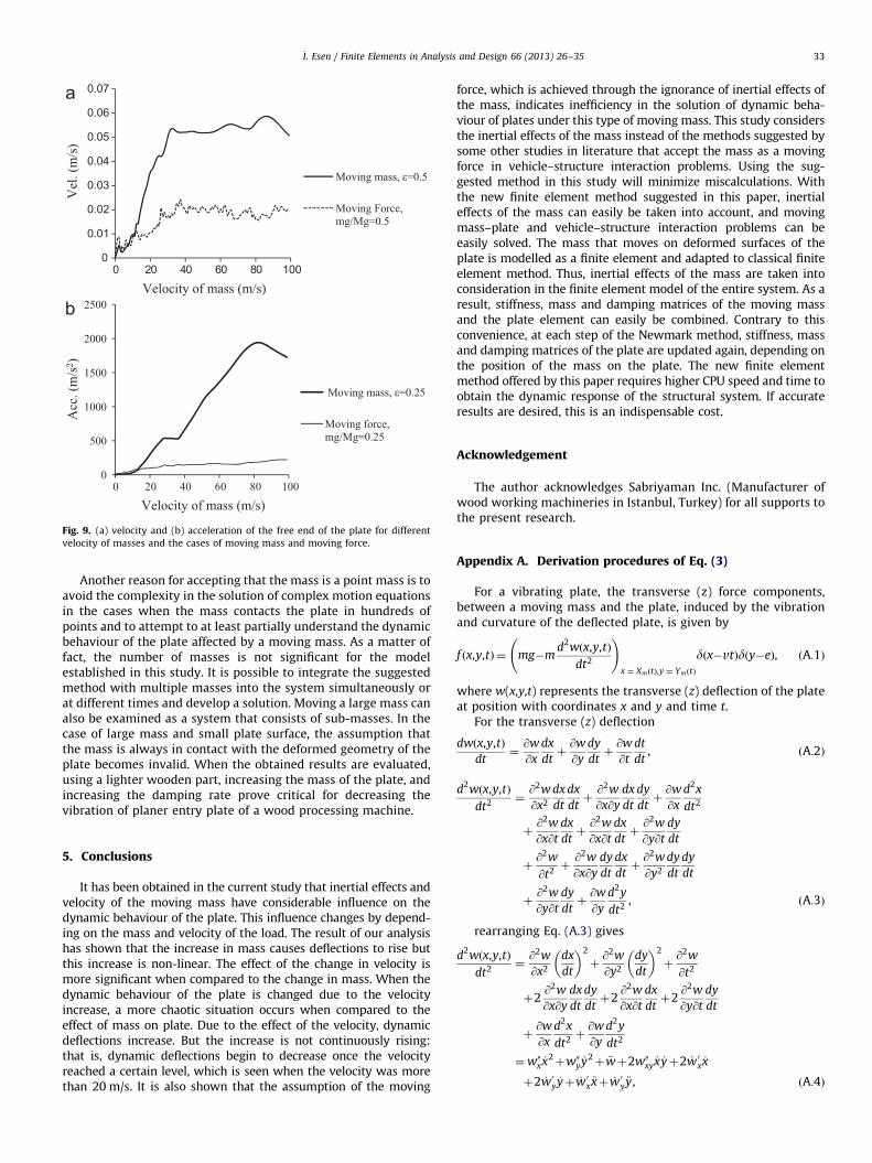
Velocities and accelerations of the middle point of the free endof the plate during vibration are given in Fig. 9a and b. In bothvelocity and acceleration curves, huge differences can be seenbetween moving mass and moving force assumptions. In smallermass-travel velocities, i.e., between 0 and 15 m/s, velocity andacceleration change with minor differences for both situations.Under the high velocity, the increases in both velocity andacceleration curves were massive; taking this viewpoint, it canbe understood that the ignorance of inertial effect of the massresulted in a failure to display the real behaviour of the plateunder moving mass.
The contact between the moving mass and the plate is notactually a point contact. In this paper, the case, when the contactis a point contact, meaning that the mass focuses on a certainpoint, is examined. The reason for this limitation is to be able tomake a comparison with the papers in literature that investigatemoving mass and carrier structures like bridges within thevehicle–structure interaction and then to approve of the applica-tion and conformity of the suggested method with previousstudies in literature.
Fig. 9. (a) velocity and (b) acceleration of the free end of the plate for different
velocity of masses and the cases of moving mass and moving force.
_I. Esen / Finite Elements in Analysis and Design 66 (2013) 26–35 33
Another reason for accepting that the mass is a point mass is toavoid the complexity in the solution of complex motion equationsin the cases when the mass contacts the plate in hundreds ofpoints and to attempt to at least partially understand the dynamicbehaviour of the plate affected by a moving mass. As a matter offact, the number of masses is not significant for the modelestablished in this study. It is possible to integrate the suggestedmethod with multiple masses into the system simultaneously orat different times and develop a solution. Moving a large mass canalso be examined as a system that consists of sub-masses. In thecase of large mass and small plate surface, the assumption thatthe mass is always in contact with the deformed geometry of theplate becomes invalid. When the obtained results are evaluated,using a lighter wooden part, increasing the mass of the plate, andincreasing the damping rate prove critical for decreasing thevibration of planer entry plate of a wood processing machine.
5. Conclusions
It has been obtained in the current study that inertial effects andvelocity of the moving mass have considerable influence on thedynamic behaviour of the plate. This influence changes by depend-ing on the mass and velocity of the load. The result of our analysishas shown that the increase in mass causes deflections to rise butthis increase is non-linear. The effect of the change in velocity ismore significant when compared to the change in mass. When thedynamic behaviour of the plate is changed due to the velocityincrease, a more chaotic situation occurs when compared to theeffect of mass on plate. Due to the effect of the velocity, dynamicdeflections increase. But the increase is not continuously rising:that is, dynamic deflections begin to decrease once the velocityreached a certain level, which is seen when the velocity was morethan 20 m/s. It is also shown that the assumption of the moving
force, which is achieved through the ignorance of inertial effects ofthe mass, indicates inefficiency in the solution of dynamic beha-viour of plates under this type of moving mass. This study considersthe inertial effects of the mass instead of the methods suggested bysome other studies in literature that accept the mass as a movingforce in vehicle–structure interaction problems. Using the sug-gested method in this study will minimize miscalculations. Withthe new finite element method suggested in this paper, inertialeffects of the mass can easily be taken into account, and movingmass–plate and vehicle–structure interaction problems can beeasily solved. The mass that moves on deformed surfaces of theplate is modelled as a finite element and adapted to classical finiteelement method. Thus, inertial effects of the mass are taken intoconsideration in the finite element model of the entire system. As aresult, stiffness, mass and damping matrices of the moving massand the plate element can easily be combined. Contrary to thisconvenience, at each step of the Newmark method, stiffness, massand damping matrices of the plate are updated again, depending onthe position of the mass on the plate. The new finite elementmethod offered by this paper requires higher CPU speed and time toobtain the dynamic response of the structural system. If accurateresults are desired, this is an indispensable cost.
Acknowledgement
The author acknowledges Sabriyaman Inc. (Manufacturer ofwood working machineries in Istanbul, Turkey) for all supports tothe present research.
Appendix A. Derivation procedures of Eq. (3)
For a vibrating plate, the transverse (z) force components,between a moving mass and the plate, induced by the vibrationand curvature of the deflected plate, is given by
f x,y,tð Þ ¼ mg�md2w x,y,tð Þ
dt2
!x ¼ XmðtÞ,y ¼ YmðtÞ
d x�vtð Þd y�eð Þ, ðA:1Þ
where w(x,y,t) represents the transverse (z) deflection of the plateat position with coordinates x and y and time t.
For the transverse (z) deflection
dw x,y,tð Þ
dt¼@w
@x
dx
dtþ@w
@y
dy
dtþ@w
@t
dt
dt, ðA:2Þ
d2w x,y,tð Þ
dt2¼@2w
@x2
dx
dt
dx
dtþ@2w
@x@y
dx
dt
dy
dtþ@w
@x
d2x
dt2
þ@2w
@x@t
dx
dtþ@2w
@x@t
dx
dtþ@2w
@y@t
dy
dt
þ@2w
@t2þ@2w
@x@y
dy
dt
dx
dtþ@2w
@y2
dy
dt
dy
dt
þ@2w
@y@t
dy
dtþ@w
@y
d2y
dt2, ðA:3Þ
rearranging Eq. (A.3) gives
d2w x,y,tð Þ
dt2¼@2w
@x2
dx
dt
� �2
þ@2w
@y2
dy
dt
� �2
þ@2w
@t2
þ2@2w
@x@y
dx
dt
dy
dtþ2
@2w
@x@t
dx
dtþ2
@2w
@y@t
dy
dt
þ@w
@x
d2x
dt2þ@w
@y
d2y
dt2
¼w00x _x2þw00y _y
2þ €wþ2w00xy
_x _yþ2 _w 0x _x
þ2 _w0y _yþ _w0x €xþ _w 0y €y, ðA:4Þ
_I. Esen / Finite Elements in Analysis and Design 66 (2013) 26–3534
Appendix B. Solution steps for Newmark integration method.
Using Newmark integration method, the solution of Eq. (13) isobtained according to the following steps. (16):
I.
Determine the integration parameters b and g and mag-nitude of the time interval Dt. In this study b¼0.25 andg¼0.5 is accepted for integration accuracy and stability.
II.
Calculate integration constants:
a0 ¼1
bDt2 , a1 ¼g
bDt , a2 ¼1
bDt , a3 ¼1
2b�1,
a4 ¼gb�1, a5 ¼
Dt2
gb�2� �
, a6 ¼Dt 1�g� �
, a7 ¼ gDt:
ðB:1Þ
III.
Using Sections 2.3 and 2.4, determine the mass, stiffnessand damping ½M�, ½K� and ½C� matrices at tn(¼tn�1þDt)time.
IV.
Calculate effective stiffness matrix at (¼tn�1þDt) time:
½_K � ¼ ½K�þa0½M�þa1½C�: ðB:2Þ
V.
Calculate effective force f_F ðtÞg at time tn(¼tn�1þDt):
where f €u tn�1ð Þg, f _u tn�1ð Þg, fu tn�1ð Þg are, respectively, theinitial conditions for the accelerations, velocities anddisplacements of the structural system at time t¼t0¼0.
VI.
Calculate deflections at tn time:
fu tnð Þg ¼ ½_K ��1f
_F tnð Þg: ðB:4Þ
VII.
Calculate accelerations and velocities at tn time:
f €u tnð Þg ¼ a0 fu tnð Þg�fu tn�1ð ÞgÞ�a2f _u tn�1ð Þg�a3f €u tn�1ð Þg,ð
ðB:5Þ
f _u tnð Þg ¼ f _u tn�1ð Þgþa6f €u tn�1ð Þgþa7f €u tnð Þg: ðB:6Þ
Steps III–VII, t¼tn¼tn�1þDt (n¼1, 2, 3,y. and t0¼0) arerepeated for all time steps and deflections fu tnð Þg, velocitiesf _u tnð Þg and accelerations f €u tnð Þgof the structural system arecalculated.
Appendix C. Derivation procedure of Eq. (11)
If the equation which expresses the relation between deflec-tion and shape functions given in Eq. (10) is substituted at theequation for nodal forces of plate element given in Eq. (7), nodalforce equations are obtained as follows.
f s1¼�N1mgþN1mv2 N001u1þN002u2þ � � � þN0016u16
� �þN1 N1 €u1þN2 €u2þ � � � þN16 €u16ð Þ
þN1 N01 _u1þN02 _u2þ � � � þN016_u16
� �,
f s2¼�N2mgþN2mv2 N001u1þN002u2þ � � � þN0016u16
� �þN2 N1 €u1þN2 €u2þ � � � þN16 €u16ð Þ
þN2 N01 _u1þN02 _u2þ � � � þN016_u16
� �,
:f s3¼�N3mgþN3mv2 N001u1þN002u2þ � � � þN0016u16
� �þN3 N1 €u1þN2 €u2þ � � � þN16 €u16ð Þ
þN3 N01 _u1þN02 _u2þ � � � þN016_u16
� �,:::
f s15¼�N15mgþN15mv2 N001u1þN002u2þ � � � þN0016u16
� �þN15 N1 €u1þN2 €u2þ � � � þN16 €u16ð Þ
þN15 N01 _u1þN02 _u2þ � � � þN016_u16
� �,
f s16¼�N16mgþN16mv2 N001u1þN002u2þ � � � þN0016u16
� �þN16 N1 €u1þN2 €u2þ � � � þN16 €u16ð Þ
þN16 N01 _u1þN02 _u2þ � � � þN016_u16
� �, ðC:1Þ
When the equities in Eq. (C.1) are organized in the form of amatrix, the following matrix equation is obtained.
f ¼ m½ � €u
þ c½ � _u
þ k� �
uf g, ðC:2Þ
References
[1] L., Fryba, Vibration Solids and Structures Under Moving Loads, ThomasTelford House, London, 1999.
[2] H. Takabataka, Dynamic analysis of rectangular plates with stepped thicknesssubjected to moving loads including additional mass, J. Sound Vib. 213 (1998)829.
[3] E. Ghafoori, M. Asghari, Dynamic analysis of laminated composite platestraversed by a moving mass based on a first-order theory, Compos. Struct. 92(2010) 1865.
[4] M.R. Shadnam, M. Mofid, J.E. Akin, On the dynamic response of rectangularplate with moving mass, Thin Walled Struct. 39 (2001) 797.
[5] J.S. Wu, M.L. Lee, T.S. Lai, The dynamic analysis of a flat plate under a movingload by the finite element method, Int. J. Numer. Methods Eng. 193 (1996)307.
[6] D.M. Yoshida, W. Weaver, Finite element analysis of beams and plates withmoving loads, Publ. Int. Assoc. Bridges Struct. Eng. 31 (1971) 79–195.
[7] J.J. Wu, Use of equivalent beam models for the dynamic analyses of beam-plates under moving forces, Comput. Struct. 81 (2003) 2749.
[8] J.A. Gbadeyan, S.T. Oni, Dynamic behaviour of beams and rectangular platesunder moving loads, J. Sound Vib. 182 (5) (1995) 677.
[9] J. Renard, M. Taazount, Transient responses of beams and platessubject to travelling load: miscellaneous results, Eur. J. Mech. A. Solids 21(2002) 301.
[10] _I. Esen, Dynamic response of a beam due to an accelerating moving massusing moving finite element approximation, Math. Comput. Appl. 16 (1)(2011) 171.
[11] _I. Esen, Dynamic Analysis of Overhead Crane Beams Under Moving Loads,Ph.D. Thesis, Istanbul Technical University, 2008.
[12] _I. Gerdemeli, D. Ozer, _I. Esen, Dynamic analysis of overhead crane beamunder moving loads, Proceedings of the Fifth. European Congress on Compu-tational Methods in Applied Sciences and Engineering (ECCOMAS 2008),Venice, Italy (2008).
[13] _I. Gerdemeli, _I. Esen, D. Ozer, Dynamic response of an overhead crane beamdue to a moving mass using moving finite element approximation, Key Eng.Mater. 450 (2011) 99.
[14] R. Szilard, Theories and Applications of Plate Analysis, Wiley, New Jersey,2004.
[15] H. Bachmann, et al., Vibration Problems in Structures, BirkhauserVerlag,Berlin, 1995.
[16] K.J. Bathe, Finite element Procedure in Engineering Analysis, Prentice-Hall,Englewood Cliffs (NJ), 1982.
[17] R.W. Clough, J. Penzien, Dynamics of Structures, third ed., Computers andStructures, Inc., Berkeley, 2003.
[18] L. WilsonE., Static and Dynamic Analysis of Structures, Chapter 20: DynamicAnalysis by Numerical Integration, Computers and Structures Inc., Berkeley,2002.
[19] A.O. Cifuentes, Dynamic response of a beam excited by a moving mass, FiniteElem. Anal. Des. 5 (1989) 237.
[20] M.R. Taheri Dynamic Response of Plates to Moving Loads, Structural Impe-dance and Finite Element Methods, Ph.D. Dissertation, Purdue University, IN;1987.
[21] M.H. Kadivar, S.R. Mohebpour, Finite element dynamic analysis ofunsymmetric composite laminated beams with shear effect and rotary
_I. Esen / Finite Elements in Analysis and Design 66 (2013) 26–35 35
inertia under the action of moving loads, Finite Elem. Anal. Des. 29 (1998)259.
[22] L. Meirovitch, Analytical Methods in Vibrations, The Macmillan Company,New York, 1967.
[23] J.N. Reddy, Energy and Variational Methods in Applied Mechanics, John Wileyand Sones, NewYork, 1984.
[24] M.T. Ahmadian, R.A. Jafari-Talookolaei, E. Esmailzadeh, Dynamics of alaminated composite beam on Pasternak visco-elastic foundation subjectedto a moving oscillator, J. Vib. Control 14 (6) (2008) 807.
[25] E. Sharbati, W. Szyszkowski, A new FEM approach for analysis of beams withrelative movements of masses, Finite Elem. Anal. Des. 47 (2011) 1047.
[26] W. Szyszkowski, E. Sharbati, On the FEM modelling of mechanical systems
controlled by relative motion of a member: a pendulum–mass interactiontest case, Finite Elem. Anal. Des. 45 (2009) 730.
[27] U. Lee, Separation between the Flexible Structure and the moving masssliding on it, J. Sound Vib. 209 (5) (1998) 867.