A New Method for High-Speed Motion-Picture Photography of Transparent Drops Albert Pfeiffer A new method applicable to high-speed motion-picture photography of moving transparent drops is described. Previous methods have not considered the optical properties of drops as image-forming, spherical convex lenses. By taking advantage of this property of transparent drops, it has been possible to produce sufficient light contrast between the drop and its illuminated background to enable drops to be photographed. It is concluded that high-speed motion-picture photography of transparent drops can be accomplished where it is possible to produce sufficient light contrast between the drop and its back- ground to make the drop visible. Two highly satisfactory methods of producing this contrast were tested experimentally and found to produce an excellent technique that could be used for a variety of investi- gations in the aerosol field. Drop photography is a very useful tool for investiga- tions in the fields of evaporation, condensation, coat- ing, stability, settling (mass subsidence), impaction, fluid dynamics, and production of aerosols. Only drops that are visible in a general optical sense, how- ever, can be photographed. The following methods have been used previously in an attempt to produce sufficient light contrast to make transparent drops optically distinguishable: dark-field illumination,' Schlieren, 2 shadow, 3 and sil- houette. 4 The latter method shows the silhouette of the drop in direct light. In these older methods, the drop usually photographs black against a bright back- ground. When the background is a dark color, it is impossible to obtain satisfactory photographs. Fur- thermore, these methods will work only if the optical axis of the camera and the illuminating light beam form a narrow limited angle with each other. All previous methods have failed to consider that the transparent drops are actually image-forming, spherical convex lenses. When these properties of the drop were studied, it was found possible to produce a sharp contrast between a drop and its surroundings by diffused reflected light. The author is with the U.S. Army, Chemical Corps Research and Development Command, Physicochemical Research Division, Chemical Research and Development Laboratories, Army Chemical Center, Maryland. Received 14 September 1962. Basic Optical Principles Elements of Optical System The basic optical system consists of the (1) light source, (2) drop, (3) limited background, (4) unlimited or general background, and (5) objective lens and ground glass of the camera (Fig. 1). Light rays from the light source incident upon the general background are reflected diffusely through the drop and objective lens, and the resultant image is brought into focus on the ground glass of the camera. As explained later, the transparent drop in this system acts as an image- forming optical lens; thus, the basic laws of optics as applied to lenses may be applied to this drop. Experimental Method Visibility of Drop A drop can be photographed only if it is visible, i.e., optically distinguishable from its surroundings. If a convex lens is used to look at some object, e.g., a page of print, a reverse picture of a certain area of the page can be seen in the lens (Fig. 2) when the lens, the eye, and the print are at certain distances from one another. If the object is large enough, it is possible to see two images simultaneously-a direct image of the print (seen around the outside of the lens) and an inverted imageof the print within the lens. This contrast between images enables the viewer to distinguish the lens itself. Since a transparent drop is also a lens, it too can be distinguished under similar December 1963 / Vol. 2, No. 12 / APPLIED OPTICS 1287
Transcript
A New Method for High-Speed Motion-Picture
Photography of Transparent Drops
Albert Pfeiffer
A new method applicable to high-speed motion-picture photography of moving transparent drops isdescribed. Previous methods have not considered the optical properties of drops as image-forming,spherical convex lenses. By taking advantage of this property of transparent drops, it has been possibleto produce sufficient light contrast between the drop and its illuminated background to enable drops to bephotographed. It is concluded that high-speed motion-picture photography of transparent drops canbe accomplished where it is possible to produce sufficient light contrast between the drop and its back-ground to make the drop visible. Two highly satisfactory methods of producing this contrast were testedexperimentally and found to produce an excellent technique that could be used for a variety of investi-gations in the aerosol field.
Drop photography is a very useful tool for investiga-tions in the fields of evaporation, condensation, coat-ing, stability, settling (mass subsidence), impaction,fluid dynamics, and production of aerosols. Onlydrops that are visible in a general optical sense, how-ever, can be photographed.
The following methods have been used previouslyin an attempt to produce sufficient light contrast tomake transparent drops optically distinguishable:dark-field illumination,' Schlieren,2 shadow,3 and sil-houette.4 The latter method shows the silhouette ofthe drop in direct light. In these older methods, thedrop usually photographs black against a bright back-ground. When the background is a dark color, it isimpossible to obtain satisfactory photographs. Fur-thermore, these methods will work only if the opticalaxis of the camera and the illuminating light beamform a narrow limited angle with each other.
All previous methods have failed to consider thatthe transparent drops are actually image-forming,spherical convex lenses. When these properties ofthe drop were studied, it was found possible to producea sharp contrast between a drop and its surroundingsby diffused reflected light.
The author is with the U.S. Army, Chemical Corps Researchand Development Command, Physicochemical Research Division,Chemical Research and Development Laboratories, ArmyChemical Center, Maryland.
Received 14 September 1962.
Basic Optical Principles
Elements of Optical System
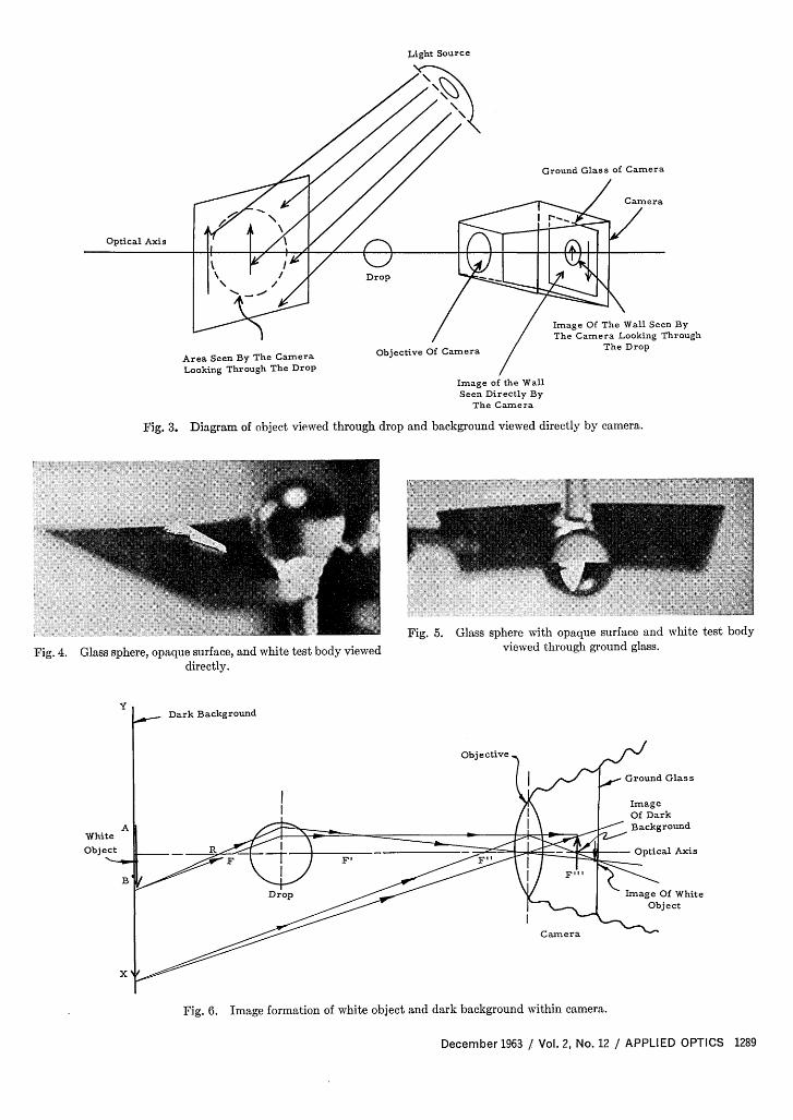
The basic optical system consists of the (1) lightsource, (2) drop, (3) limited background, (4) unlimitedor general background, and (5) objective lens andground glass of the camera (Fig. 1). Light rays fromthe light source incident upon the general backgroundare reflected diffusely through the drop and objectivelens, and the resultant image is brought into focus onthe ground glass of the camera. As explained later,the transparent drop in this system acts as an image-forming optical lens; thus, the basic laws of optics asapplied to lenses may be applied to this drop.
Experimental Method
Visibility of Drop
A drop can be photographed only if it is visible,i.e., optically distinguishable from its surroundings.If a convex lens is used to look at some object, e.g.,a page of print, a reverse picture of a certain area ofthe page can be seen in the lens (Fig. 2) when the lens,the eye, and the print are at certain distances from oneanother. If the object is large enough, it is possibleto see two images simultaneously-a direct image ofthe print (seen around the outside of the lens) and aninverted image of the print within the lens.
This contrast between images enables the viewer todistinguish the lens itself. Since a transparent dropis also a lens, it too can be distinguished under similar
conditions. Furthermore, the drop can be photo-graphed when these images are in contrast (Fig. 3).
Image Formation of Drop and Background onGround Glass of Camera
In order to develop a method by which sufficientlight contrast could be produced for satisfactory dropphotography, first it was necessary to determine howimages of the drop and background relate to each other.By first substituting transparent glass spheres 5 mm indiameter for drops, it was possible to develop and testcontrast techniques at the optical bench on a largescale.
Figure 4 shows the normal relationship between theglass sphere and the background elements. A whitetest body with a groove on its left side was placed uponthe dark opaque surface. Figure 5 shows how thebackground appears when photographed through the
Light S.-.ce
Are Seen By Eye L-okingOut.ide Of Les
Are Sen By Ey. Looking Throgh Lens
Fig. 2. Diagram of object viewed in and around convex lens.
drop. Although the background and sphere nowappear in an inverted position, the position of thewhite test body remains unchanged. (The grooveremains on the left side.)
This phenomenon can be explained graphically(Fig. 6): From any point on the white object AB,any number of light rays can be constructed. Forpurposes of illustration, consider two such rays leavingpoint B on the white object. The first ray passesthrough the R-point of the drop as a chief ray; it isrefracted by the drop and passes on through the centerof the objective lens. The second ray leaving point Bpasses through the focal point F of the drop, is refractedby the drop into a path parallel to the optical axis,strikes the objective lens where it is again refracted,and passes on through focal point F"' of the lens. Thetwo rays will intersect at a point behind the objectivelens within the camera. To obtain a sharp image ofthe white object, the ground glass must be positionedat this exact point.
Next, consider two rays leaving point X on thedarker background. The first ray passes directlythrough the center of the objective lens. The secondray passes through the focal point F" of the objectivelens and is refracted by the lens into a path parallelto the optical axis. These rays will also intersect.Their point of intersection, however, is in a differentimage plane from the one in which the image of thewhite object is located. This is a desirable factor inthe photography of the white object.
The inversion of the darker background with re-spect to the position of the white object within thecamera can be easily seen now from this graphicalconstruction.
Fig. 7. Typical picture of drop and backgrounds seen on groundglass of camera.
With the light source available in this work, picturesof moving drops could be obtained having a radiusas small as 30 /.z. It should not be difficult to obtainpictures of drops as small as 3 u if the light source were100 times more intense, but for drops as small as 3 i,
Fig. 8. Photograph of glass sphere viewed against illuminatedlimited background and dark general background.
Fig. 9. Experimental setup used to photograph transparentdrops against dark limited background and illuminated generalbackground: high-speed motion-picture camera, light source,light shield, atomizer, limited background shown by arrow,
general background.
the geometrical optics analysis would not be expectedto be sufficiently rigorous.
To calculate the actual drop size from the pictureof a drop, one has to measure the magnification at thepoint, in the field of view, where the drop will appear.This measurement can be made by using a calibratedscale. The optical justification for this procedure ofdetermining the magnification can be derived from aconsideration of Fig. 6 and the depth of field of theparticular camera used.
Procedure
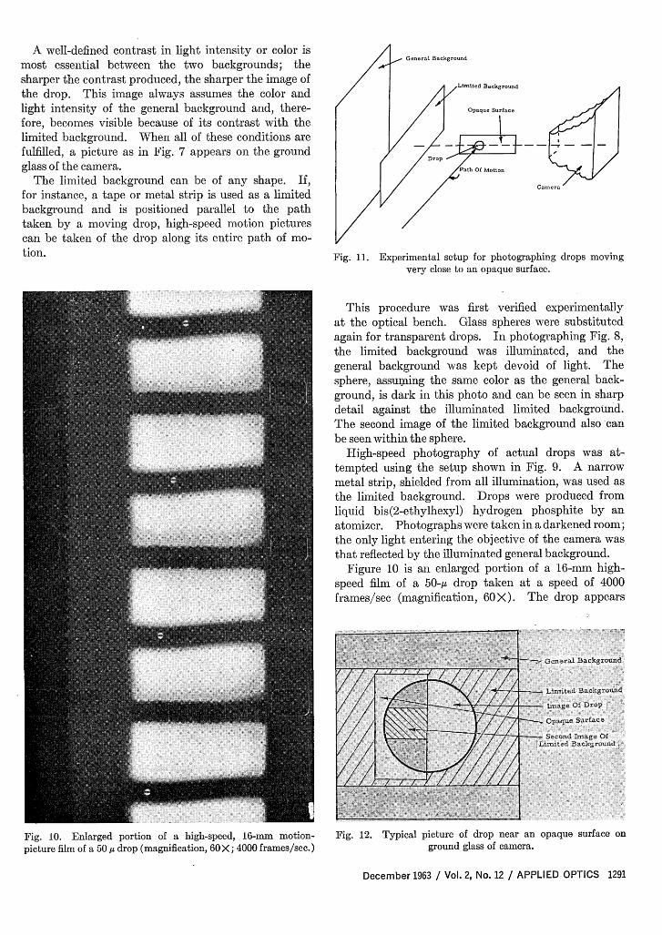
In this method, the drop is photographed with twobackgrounds contrasting in either color or intensity ofillumination (Fig. 1). The general background isunlimited in size. The limited background, however,must be large enough to give an image on the groundglass of the camera somewhat larger than the image ofthe drop. At the same time, this limited backgroundmust be small enough to give a second complete imageframed within the circumference of the drop image.
A well-defined contrast in light intensity or color is G
most essential between the two backgrounds; the GeneratBackgonnd
sharper the contrast produced, the sharper the image of /the drop. This image always assumes the color andlight intensity of the general background and, there- Opaq-eSurf ...
fore, becomes visible because of its contrast with thelimited background. When all of these conditions arefulfilled, a picture as in Fig. 7 appears on the ground , - ---
glass of the camera. P
The limited background can be of any shape. If, Came-a
for instance, a tape or metal strip is used as a limitedbackground and is positioned parallel to the pathtaken by a moving drop, high-speed motion picturescan be taken of the drop along its entire path of mo-tion. Fig. 11. Experimental setup for photographing drops moving
very close to an opaque surface.
This procedure was first verified experimentallyat the optical bench. Glass spheres were substitutedagain for transparent drops. In photographing Fig. 8,the limited background was illuminated, and thegeneral background was kept devoid of light. Thesphere, assuming the same color as the general back-ground, is dark in this photo and can be seen in sharpdetail against the illuminated limited background.The second image of the limited background also'canbe seen within the sphere.
High-speed photography of actual drops was at-tempted using the setup shown in Fig. 9. A narrowmetal strip, shielded from all illumination, was used asthe limited background. Drops were produced fromliquid bis(2-ethylhexyl) hydrogen phosphite by anatomizer. Photographs were taken in a darkened room;the only light entering the objective of the camera wasthat reflected by the illuminated general background.
Figure 10 is an enlarged portion of a 16-mm. high-speed film of a 5-p~ drop taken at a speed of 4000frames/sec (magnification, 6 >). The drop appears
Christie:, ~ ~ ~ ~ ~ ~ Goa~akS m
Fig. 10. Enlarged portion of a high-speed, 16-mm. motion- Fig. 12. Typical picture of drop near an opaque surface onpicture film of a 50 u drop (magnification, 60X; 4000 frames/sec.) ground glass of camera.
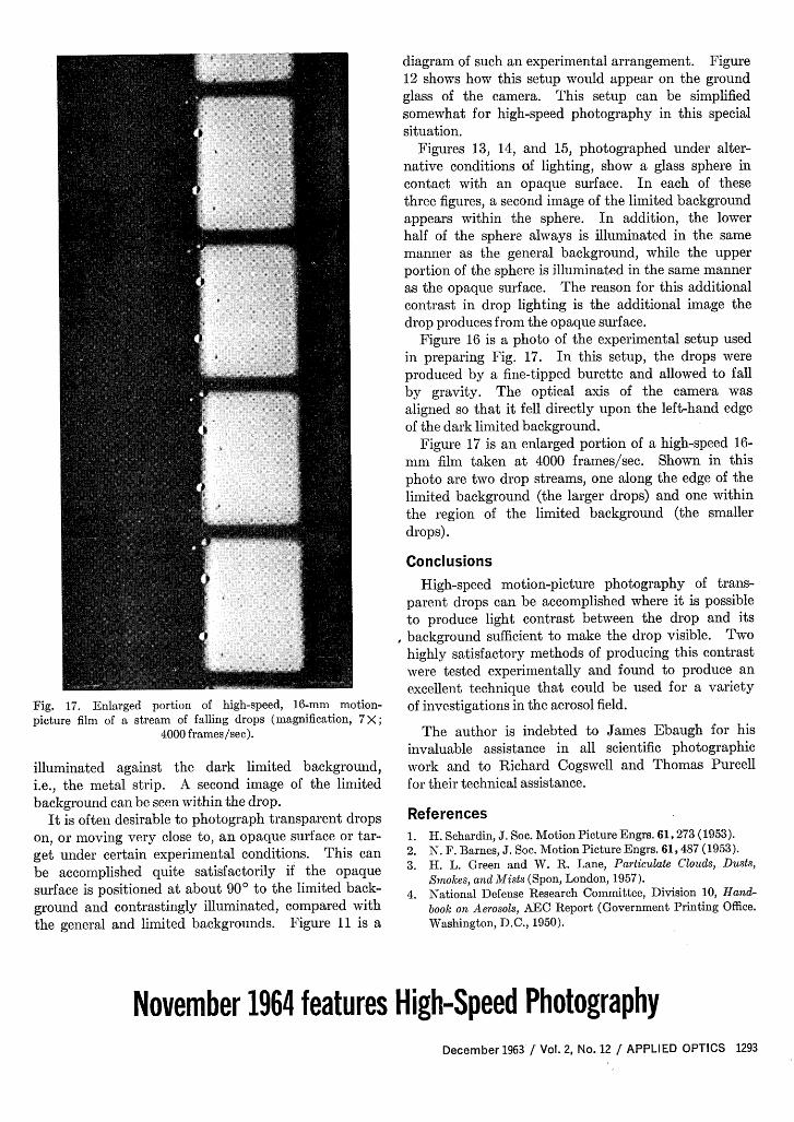
Fig. 17. Enlarged portion of high-speed, 16-mm motion-picture film of a stream of falling drops (magnification, 7X;
4000 frames/sec).
illuminated against the dark limited background,i.e., the metal strip. A second image of the limitedbackground can be seen within the drop.
It is often desirable to photograph transparent dropson, or moving very close to, an opaque surface or tar-get under certain experimental conditions. This canbe accomplished quite satisfactorily if the opaquesurface is positioned at about 90° to the limited back-ground and contrastingly illuminated, compared withthe general and limited backgrounds. Figure 11 is a
diagram of such an experimental arrangement. Figure12 shows how this setup would appear on the groundglass of the camera. This setup can be simplifiedsomewhat for high-speed photography in this specialsituation.
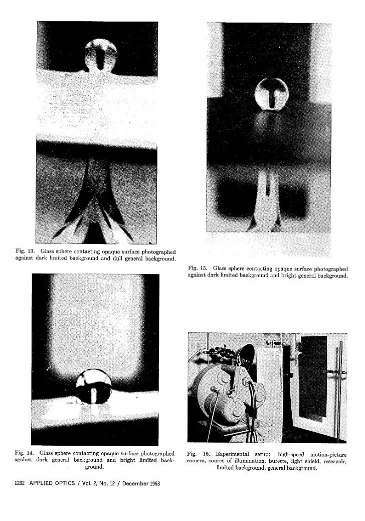
Figures 13, 14, and 15, photographed under alter-native conditions of lighting, show a glass sphere incontact with an opaque surface. In each of thesethree figures, a second image of the limited backgroundappears within the sphere. In addition, the lowerhalf of the sphere always is illuminated in the samemanner as the general background, while the upperportion of the sphere is illuminated in the same manneras the opaque surface. The reason for this additionalcontrast in drop lighting is the additional image thedrop produces from the opaque surface.
Figure 16 is a photo of the experimental setup usedin preparing Fig. 17. In this setup, the drops wereproduced by a fine-tipped burette and allowed to fallby gravity. The optical axis of the camera wasaligned so that it fell directly upon the left-hand edgeof the dark limited background.
Figure 17 is an enlarged portion of a high-speed 16-mm film taken at 4000 frames/sec. Shown in thisphoto are two drop streams, one along the edge of thelimited background (the larger drops) and one withinthe region of the limited background (the smallerdrops).
Conclusions
High-speed motion-picture photography of trans-parent drops can be accomplished where it is possibleto produce light contrast between the drop and itsbackground sufficient to make the drop visible. Twohighly satisfactory methods of producing this contrastwere tested experimentally and found to produce anexcellent technique that could be used for a varietyof investigations in the aerosol field.
The author is indebted to James Ebaugh for hisinvaluable assistance in all scientific photographicwork and to Richard Cogswell and Thomas Purcellfor their technical assistance.
References1. H. Schardin, J. Soc. Motion Picture Engrs. 61, 273 (1953).2. N. F. Barnes, J. Soc. Motion Picture Engrs. 61, 487 (1953).3. H. L. Green and W. R. Lane, Particulate Clouds, Dusts,
Smokes, and Mists (Spon, London, 1957).4. National Defense Research Committee, Division 10, Hand-
book on Aerosols, AEC Report (Government Printing Office.Washington, D.C., 1950).