Journal of Physics: Conference Series OPEN ACCESS A new MUSIC electromagnetic imaging method with enhanced resolution for small inclusions To cite this article: Yu Zhong and Xudong Chen 2008 J. Phys.: Conf. Ser. 135 012105 View the article online for updates and enhancements. You may also like Resolution improvement of dipole source localization for artificial lateral lines based on multiple signal classification Mingjiang Ji, Yong Zhang, Xiande Zheng et al. - An analytical approach to estimate the number of small scatterers in 2D inverse scattering problems Roohallah Fazli and Mansor Nakhkash - Robust multifrequency imaging with MUSIC Miguel Moscoso, Alexei Novikov, George Papanicolaou et al. - This content was downloaded from IP address 166.48.140.188 on 23/12/2021 at 23:14
Transcript
Journal of Physics Conference Series
OPEN ACCESS
A new MUSIC electromagnetic imaging methodwith enhanced resolution for small inclusionsTo cite this article Yu Zhong and Xudong Chen 2008 J Phys Conf Ser 135 012105
View the article online for updates and enhancements
You may also likeResolution improvement of dipole sourcelocalization for artificial lateral lines basedon multiple signal classificationMingjiang Ji Yong Zhang Xiande Zhenget al
-
An analytical approach to estimate thenumber of small scatterers in 2D inversescattering problemsRoohallah Fazli and Mansor Nakhkash
-
Robust multifrequency imaging withMUSICMiguel Moscoso Alexei Novikov GeorgePapanicolaou et al
-
This content was downloaded from IP address 16648140188 on 23122021 at 2314
A new MUSIC electromagnetic imaging method with
enhanced resolution for small inclusions
Yu Zhong and Xudong Chen
Department of Electrical and Computer EngineeringNational University of Singapore Singapore 117576
E-mail zhongyunusedusg
Abstract
This paper investigates the influence of test dipole on the resolution of the multiplesignal classification (MUSIC) imaging method applied to the electromagnetic inverse scatteringproblem of determining the locations of a collection of small objects embedded in a knownbackground medium Based on the analysis of the induced electric dipoles in eigenstates analgorithm is proposed to determine the test dipole that generates a pseudo-spectrum withenhanced resolution The amplitudes in three directions of the optimal test dipole are notnecessarily in phase ie the optimal test dipole may not correspond to a physical direction inthe real three-dimensional space In addition the proposed test-dipole-searching algorithm isable to deal with some special scenarios due to the shapes and materials of objects to whichthe standard MUSIC doesnrsquot apply
1 Introduction
The multiple signal classification (MUSIC) algorithm has been of great interest in the inversescattering community since it was proposed to locate point-like scatterers in 2000 [1] Positions ofthe small objects are retrieved from the multistatic response (MSR) matrix generated by an arrayof transceivers [2ndash6] MUSIC imaging method was first applied to acoustic imaging where scalarfield is involved The test function used to generate the MUSIC pseudo-spectrum is the Greenrsquosfunction of the background medium associated with a monopole source [357] Recently MUSICalgorithm was generalized to electromagnetic imaging of small three-dimensional targets [6 8]In case of electromagnetic scattering the induced sources inside small objects are electric dipolesandor magnetic dipoles not monopoles any more The test function that is used to generatethe MUSIC pseudo-spectrum is chosen to be the Greenrsquos function of the background mediumassociated with an electric or magnetic dipole source with an arbitrary orientation [6 8]
This paper focuses on two phenomena in electromagnetic MUSIC imaging that are differentfrom the ones in acoustic MUSIC imaging The first is regarding the spatial resolution in thepresence of noise In acoustic imaging the test function used to generate MUSIC pseudo-spectrum is the Greenrsquos function of the background medium associated with a monopole sourceIn electromagnetic imaging the test function that is used to generate the MUSIC pseudo-spectrum is chosen to be the Greenrsquos function of the background medium associated with anelectric or magnetic dipole Although the test dipole can be oriented in any direction in noisefree case for non-degenerate scatterers the MUSIC pseudo-spectrum depends noticeably on theorientation of the test dipole in noisy scenarios The second phenomenon is regarding degenerate
6th International Conference on Inverse Problems in Engineering Theory and Practice IOP PublishingJournal of Physics Conference Series 135 (2008) 012105 doi1010881742-65961351012105
ccopy 2008 IOP Publishing Ltd 1
scatterers in which only one or two independent components of an electric or magnetic dipoleare induced inside some small scatterers due to special shapes or composing materials of thescatterers For example a needle-like or disk-like small object may present only one or twodominant components of induced electric dipoles For an anisotropic small sphere when somecomponents in the principal axes of its permittivity tensor are equal to the permittivity ofthe background medium the number of independent electric dipole components are less thanthree In degenerate cases standard MUSIC algorithms [68] do not work because an arbitrarilychosen direction of test dipole is not necessarily located in the space spanned by actually inducedindependent dipole components
The choice of the test dipole direction has been investigated in [9 10] in two and threedimensional cases respectively to deal with degenerate scatterers However to the best ofour knowledge the effect of the choosing test dipole direction on the resolution of imaginghas not been investigated In this paper we propose an algorithm to obtain the directionof the test dipole that yields enhanced resolution and it can also deal with degenerate casesCompared with the previous MUSIC algorithms [68ndash10] that search for the test dipole directionso that the corresponding Greenrsquos function vector is orthogonal to the noise space that is theorthogonal complement to the range of the MSR matrix the proposed algorithm determines thetest dipole direction so that the corresponding Greenrsquos function vector is in the space spannedby the dominant eigenvectors of the MSR matrix Analysis of the induced electric dipoles ineigenstates provides the physical insight of the proposed method Theoretical and numericalresults show that three components of the optimal test dipole are not necessarily in phase iethe optimal test dipole may not correspond to a physical direction in the real three-dimensionalspace The proposed algorithm was tested through numerical simulations and was found to notonly provide better resolution than the standard MUSIC algorithm but also work well in thepresence of degenerate objects
2 Forward scattering problem
Consider M three-dimensional objects that are illuminated by time-harmonic electromagneticwaves radiated by an array of N antenna units The antenna units are located at rprime1 r
prime2 r
primeN
and each consists of 3 small dipole antennas oriented in the x y and z direction with the samelength l and driving current Iix Iiy Iiz respectively i = 1 2 N The M scatterers canbe of any shape but we consider only spherical or ellipsoidal objects in this paper for ease ofpresenting The size of each scatterer is much smaller than the wavelength so that Rayleighscattering occurs The centers of the scatterers are located at r1 r2 rM The scatterers aremade of isotropic or anisotropic materials The shape and composing material of each smallscatterer determine its polarization tenor macrξj [11 12] which relates the induced electric current
dipole Il(rj) inside the object to the total incident electric field Eint (rj) by Il(rj) = macrξj middotE
int (rj)
j = 1 2 M Expressions for macrξj for isotropic and anisotropic spheres and ellipsoids can befound in Ref [11] In this paper we assume all scatterers are non-magnetic and the backgroundmedium is free space
By using the Foldy-Lax equation the multi-static response (MSR) matrix that relatesscattered fields to driving current dipoles is given by [8 10]
identity matrix micro0 is the permeability of free space and macrΦ(j jprime) is null for j = jprime or is
imicro0macrG0(rj rjprime) for j 6= jprime with macrG0(r r
prime) being the dyadic Greenrsquos function in free space [13]The MSR matrix is characteristic of the collection of scatterers for given sets of transceivers atthe frequency of operation
6th International Conference on Inverse Problems in Engineering Theory and Practice IOP PublishingJournal of Physics Conference Series 135 (2008) 012105 doi1010881742-65961351012105
2
3 The MUSIC algorithm
31 Standard MUSIC algorithm
The MSR matrix macrK maps C3N the vector space of complex 3N -tuples to its range Sr sube C3N From the singular value decomposition (SVD) analysis [14] the MSR matrix could be represented
as macrK middot vp = σpup and macrKlowastmiddot up = σpvp p = 1 2 3N where the superscript lowast denotes
the Hermitian The vector space C3N can be decomposed into the direct sum of the rangeSr = spanup σp gt 0 and the orthogonal complement space Sn = spanup σp = 0 that isreferred to as noise space Consider non-degenerate scatterers in the absence of noise threeindependent electric current dipole components are induced in each scatterer and the scatteredfield Es is in the space S0 spanned by the background Greenrsquos function vectors associated withthe x y and z components of electric dipoles evaluated at the position of each scatterer ieEs isin S0 = span
Gx(rj) Gy(rj) Gz(rj) j = 1 2 M
where Gx(rj) Gy(rj) and Gz(rj)
are the [3(j minus 1) + 1]th [3(j minus 1) + 2]th and [3(j minus 1) + 3]th column of matrix macrR respectivelyGreenrsquos function vector Gl(r) l = x y z evaluated at an arbitrary position r can be definedsimilarly In this case it is easy to conclude that two subspaces Sr and S0 are identical [238]Due to the orthogonality between the range Sr and the noise space Sn we have
∣
∣ulowastpGl(rm)∣
∣ = 0and for σp = 0 m = 1 2 M and l = x y z The standard MUSIC algorithm [6 8] definesthe following pseudo-spectrum
Φ(r) =1
sum
σp=0
∣
∣ulowastpf(r)∣
∣
2 (2)
where test function f(r) can be any linear combination of Gx(r) Gy(r) and Gz(r) Thispseudo-spectrum becomes infinite at the position of every scatterer
32 MUSIC algorithm with the optimal test dipole direction
In degenerate cases however since the independent electric dipoles induced in a degeneratescatterer is less than three an arbitrarily chosen direction of test dipole is not necessarily locatedin the space spanned by actually induced independent dipole components Thus the standardMUSIC algorithm may fail to detect the degenerate scatterer [10] In addition even if there isno degenerate scatterers when scattered fields are noise contaminated the performance of theMUSIC algorithm is found to noticeably depend on the orientation of the test dipole
To find the optimal test dipole direction it is equivalent to determine a isin C3 subject to
||a|| = 1 so that the solution x to the equation
macrK middot x = macrG(r) middot a (3)
is most robust in the presence of noise where macrG(r) = [Gx(r) Gy(r) Gz(r)] The SVD of macrK isgiven by
macrK =
3Nsum
i=1
uiσivlowasti (4)
Assume eigenvalues are in non-increasing order σ1 ge σ2 ge ge σ3N ge 0 The least squaressolution of x is given by
x =3Nsum
i=1
ulowasti middotmacrG(r) middot a
σi
vi (5)
Note that the value of 1σi
is large for a small σi To obtain a stable solution x we should find a
so that ulowasti middotmacrG(r) middot a is non-zero for only the first few items Due to the orthogonality of ui we
6th International Conference on Inverse Problems in Engineering Theory and Practice IOP PublishingJournal of Physics Conference Series 135 (2008) 012105 doi1010881742-65961351012105
3
need to find a so that macrG(r) middot a is a linear combination of the first few ui
Lsum
i=1
λiui = macrG(r) middot a (6)
The proposed MUSIC algorithm is based on the analysis of the induced electric currentdipoles in the eigenstate which is referred to as the eigen-dipole hereafter Assume that the
current in the jth scatterer in the ith eigen-state is equal to J(i)j We have
ui =Msum
j=1
macrG(rj) middot J(i)j i = 1 2 L (7)
In the absence of noise (7) is exactly hold whereas in the presence of noise the quantities inthe left is approximately equal to that of the right and their difference is equal to the noise Thesubstitution of (7) into (6) yields
Msum
j=1
macrG(rj) middot
Lsum
i=1
λiJ(i)j = macrG(r) middot a (8)
There are two cases to be considered (a) when the test position r is not at any of the scatterersrj and (b) r is at one of the scatterers
Note that the Greenrsquos function vector macrG(r) are linearly independent to each other [5 6]When the test position r is not at any of the scatterers (8) is hold only when a = 0 and λi = 0
Therefore for any dipole direction a which satisfies ||a|| = 1 ulowasti middotmacrG(r) middot a is not equal to zero
for all 3N left singular vectors ui In this case the solution x is the linear combination of all3N right eigenvectors vi as shown in (5) The norm of x is large and it is not stable due to thepresence of small σi
When r is at one of the scatterers for example r = r1 (8) requires
Lsum
i=1
J(i)1 λi = a (9a)
Lsum
i=1
J(i)j λi = 0 j = 2 3 M (9b)
Eq (9b) amounts to determining the minimum value of L so that J (1) J (2) J (L) are linearly
dependent where J (i) is a column vector of length 3(M minus 1) consisting of J(i)j j = 2 3 M
Therefor when the test point r is at one of the scatterers the value of minimum L is equalto one plus the total number of independent dipoles induced in other scatterers For examplefor M isotropic spheres the value of L equals to 3M minus 2 It is stressed that the algorithmalso applies to degenerate cases When the nontrivial λi i = 1 2 L obtained from (9b) areplugged into (9a) the resulting a is generally a complex value When we force the vector a tobe real more eigen-states are needed to solve (9b) Thus from (5) we know that the solution isnot as robust as the one obtained from the previous complex a
An empirical approach to determine the approximate value of L is to find the total number ofdominant singular values from the spectrum The test dipole direction is determined by findinga isin C
3 subject to ||a|| = 1 so that macrG(r) middota is close to the space spanned by the first L dominant
6th International Conference on Inverse Problems in Engineering Theory and Practice IOP PublishingJournal of Physics Conference Series 135 (2008) 012105 doi1010881742-65961351012105
4
eigenvectors ui ie we aim at a minimum projection angle between the vector macrG(r) middot a and thespace spanned by the eigenvectors ui i = 1 2 L
a = arg maxa
sumLi=1 |u
lowasti middot
macrG(r) middot a|2
| macrG(r) middot a|2(10)
From the general eigenvalue decomposition we obtained the solution a that isgiven by the eigenvector corresponding to the maximum eigenvalue of the matrix(
macrG(r)lowast middot macrG(r))minus1 ([
macrU middot macrG(r)]lowast [
macrU middot macrG(r)])
where macrU = [u1 u2 uL]lowast Then the pseudo-
spectrum can be defined as
Φ(r) =1
1 minussumL
i=1|ulowast
imiddot macrG(r)middotamax|2
| macrG(r)middotamax|2
(11)
where amax is the optimal direction obtained by (10)
4 Numerical simulation
The inversion method proposed in previous section is tested through numerical simulations intwo scenarios noise free case and noise-contaminated case
We assume that three small spheres are located at r1 = (0084λ 0196λ 0084λ) r2 =(minus0168λminus0056λminus0112λ) and r3 = (minus0196λminus0084λ 0140λ) the first two of which areisotropic spheres with permittivity ǫ1 = ǫ2 = 2ǫ0 while the third is a rotated anisotropicsphere with permittivity tensor macrǫ3 = diag [ǫ0 3ǫ0 9ǫ0] and rotation Euler angles [8] (ψ φ θ) =(π4 π3 3π8) Here ǫ0 is the permittivity of the background free space These three spheresare electrically small with the same radius a = λ30 Note that the smallest distance between
Figure 1 Singular values and pseudo-spectrum obtained by the standard MUSICalgorithm in noise free case (a) The 10 baselogarithm of the singular values of the MSRmatrix (j = 1 2 48) (b) (c) and (d) arethe 10 base logarithm of the pseudo-spectrumin y = x + 0112λ plane obtained by thestandard MUSIC algorithm with test dipolesin x y and z directions respectively
Figure 2 Pseudo-spectrum obtained bythe proposed MUSIC algorithm in noise freecase (a) (b) (c) and (d) are the 10 baselogarithm of the pseudo-spectrum in y =x + 0112λ plane obtained by the proposedMUSIC algorithm corresponding to the L =4 5 6 and 7 cases respectively
6th International Conference on Inverse Problems in Engineering Theory and Practice IOP PublishingJournal of Physics Conference Series 135 (2008) 012105 doi1010881742-65961351012105
5
the centers of spheres is 0255λ (the distance between the second and the third one) and forthe convenience of depiction of the test results all three spheres are chosen to locate in they = x + 0112λ plane Note that from the constitutive parameters of the scatterers there areup to eight independent secondary sources induced inside the three scatterers
There are 16 antenna units employed in this simulation half of which are aligned along the yaxis while the other half aligned along the z axis in the x = minus13λ plane The two linear arraysare centered at (minus13λminus9λ 11λ) with 5λ separation distance between neighboring units
For the noise free case the MSR matrix is calculated by (1) under the aforementionedcircumstance The singular values of the MSR matrix are shown in Fig1(a) in which we seethat the first eight singular values are much larger than the rest since they are correspondingto the eight singular vectors spanning the signal space Fig1(b) Fig1(c) and Fig1(d) are thepseudo-spectrum in y = x+0112λ plane obtained by the standard MUSIC method using x- y-and z-oriented test dipole respectively Not surprisingly the standard MUSIC algorithm canonly find the first two isotropic spheres and fail to locate the third degenerate anisotropic targetHere since the pseudo-spectrum value is too large at the positions of the scatterers we plot thebase 10 logarithm of it and the horizontal and vertical axes in Fig1(b) Fig1(c) and Fig1(d)are the x and z coordinate of spatial points in y = x+ 0112λ plane so do the cases hereafterBy using (11) the pseudo-spectrum obtained by the proposed MUSIC algorithm are shown inFig2 with L = 4 5 6 and 7 From these results we see that to locate the first two isotropicspheres we only need L = 6 but to locate the third degenerate anisotropic sphere we need
Figure 3 Pseudo-spectrum obtained bythe proposed MUSIC algorithm in noise freecase when the test dipole is constrained tobe real (a) (b) (c) (d) (e) and (f) arethe 10 base logarithm of the pseudo-spectrumin y = x + 0112λ plane obtained by theproposed MUSIC algorithm corresponding tothe L = 4 5 6 7 8 and 9 cases respectively
Figure 4 Singular values and pseudo-spectrum obtained by the standard MUSICalgorithm in noise-contaminated case (30dB)(a) The 10 base logarithm of the singularvalues of the MSR matrix (j = 1 2 48)(b) (c) and (d) are the pseudo-spectrum iny = x+0112λ plane obtained by the standardMUSIC algorithm with test dipoles in x yand z directions respectively
6th International Conference on Inverse Problems in Engineering Theory and Practice IOP PublishingJournal of Physics Conference Series 135 (2008) 012105 doi1010881742-65961351012105
6
L = 7 This is due to the reason that when locating one of the first two isotropic spheres therest two spheres have only five independent induced dipoles which means that L = 6 is sufficientfor (9b) to have exact solutions but if we want to locate the third degenerate sphere the resttwo isotropic spheres have totally six independent induced dipoles thus only when L = 7 canwe solve (9b) For the L = 4 and 5 cases since the L is not large enough to solve (9b) noneof the three scatterers can be located precisely If L is further increased to 8 and 9 the resultwill be almost the same as the one in L = 7 case which are not presented here If we constrainthe test dipole to be real ie a in (10) and (11) is real the pseudo-spectrum is shown in Fig3We see that L needs to be larger in order to locate the scatterers ie to locate the first twoisotropic spheres L need to be at least 7 while to locate the third degenerate sphere L at least8 Such a phenomenon was expected based on the analysis in the previous section
For the noise-contaminated case we add additive white Gaussian noise to the MSR matrix
The noise level is quantified by the signal to noise ratio (SNR) in dB defined as 20 log10 macrKmacrκ
where macrκ is the additive white Gaussian noise and middot denotes the Frobenius norm of a matrix [2][8] In this simulation 30dB white Gaussian noise is added Fig4(a) shows the singular valuesof the noise-contaminated MSR matrix in which the singular values corresponding to the noisespace are much larger than those in the noise free case In such a case if we apply the standardMUSIC algorithm to locate the scatterers the pseudo-spectrum obtained by the test dipolesin x y and z direction are shown in Fig4(b) Fig4(c) and Fig4(d) respectively which showthat all the three test dipole directions fail to locate any of the three scatterers By using the
Figure 5 Pseudo-spectrum obtained bythe proposed MUSIC algorithm in noise-contaminated case (30dB) (a) (b) (c) (d)(e) and (f) are the pseudo-spectrum in y =x + 0112λ plane obtained by the proposedMUSIC algorithm corresponding to the L =4 5 6 7 8 and 9 cases respectively
Figure 6 Pseudo-spectrum obtained bythe proposed MUSIC algorithm in noise-contaminated case (30dB) when the testdipole is constrained to be real (a) (b)(c) (d) (e) and (f) are the pseudo-spectrumin y = x + 0112λ plane obtained by theproposed MUSIC algorithm corresponding tothe L = 4 5 6 7 8 and 9 cases respectively
6th International Conference on Inverse Problems in Engineering Theory and Practice IOP PublishingJournal of Physics Conference Series 135 (2008) 012105 doi1010881742-65961351012105
7
proposed MUSIC algorithm the pseudo-spectrum are drawn in Fig5 In Fig5 for the L = 45 6 and 7 cases similar results can be observed as in Fig2 however for the L = 8 and 9 casessome unwanted disturbance appear in between the second and the third spheres which showsthat the singular vector corresponding to the eighth singular value is contaminated by the noiseto an extent so that it cannot be regarded as in the signal space anymore We further constrainthe test dipole to be real and obtain the results shown in Fig6 from which we clearly see thatthe third sphere cannot be located precisely This result could also be predicted from the resultsshown in Fig3 and Fig5 From Fig3 we know that to locate the third degenerate case weneed the information from the singular vector corresponding to the eighth singular value whichhowever has be moderately contaminated by noise according to the result shown in Fig5
5 Conclusion
A MUSIC algorithm with choosing the optimal test dipole direction has been proposed in thispaper which not only obtains a better resolution than the standard MUSIC algorithm does butalso is able to deal with the degenerate scatterers Based on the analysis of the eigenstate of theMSR matrix the proposed MUSIC algorithm determines the test dipole direction so that thecorresponding Greenrsquos function vector is in the space spanned by the dominant eigenvectors ofthe MSR matrix In addition the three components of the optimal test dipole are not necessarilyin phase ie the optimal test dipole may not correspond to a physical direction in real three-dimensional space The proposed algorithm was tested through numerical simulations Such analgorithm is a good candidate imaging method in situations where partial-aspected low SNRdata are collected
References[1] A J Devaney ldquoSuper-resolution processing of multi-static data using time-reversal and MUSICrdquo available
at httpwwweceneuedufacultydevaneyajdpreprintshtm 2000[2] Devaney A J 2005 IEEE Trans Antennas Propag 53 1600[3] Devaney A J Marengo E A and Gruber F K 2005 J Acoust Soc Am 118 3129[4] Simonetti F 2006 Phys Rev E 73 036619[5] Kirsch A 2002 Inverse Probl 18 1025[6] Ammari H Iakovleva E Lesselier D and Perruson G 2007 SIAM Sci Comput 29 674[7] Cheney M 2001 Inverse Probl 17 591[8] Zhong Y and Chen X 2007 IEEE Trans Antennas Propag 55 3542[9] Chen X and Agarwal K 2007 accepted by IEEE Trans Antennas Propag
[10] Chen X and Zhong Y 2007 Inverse Problem submitted[11] Bohren C F and Huffman D R 1998 Absorption and Scattering of Light by Small Particles (Berlin Wiley)[12] Ammari H and Kang H 2004 Reconstruction of Small Inhomogeneities from Boundary Measurements (Berlin
Springer-Verlag)[13] Kong J A 2000 Electromagnetic Wave Theory (Cambridge MA EMW)[14] Horn A and Johnson C R 1986 Matrix Analysis (Cambridge UK Cambridge University Press)
6th International Conference on Inverse Problems in Engineering Theory and Practice IOP PublishingJournal of Physics Conference Series 135 (2008) 012105 doi1010881742-65961351012105
8
A new MUSIC electromagnetic imaging method with
enhanced resolution for small inclusions
Yu Zhong and Xudong Chen
Department of Electrical and Computer EngineeringNational University of Singapore Singapore 117576
E-mail zhongyunusedusg
Abstract
This paper investigates the influence of test dipole on the resolution of the multiplesignal classification (MUSIC) imaging method applied to the electromagnetic inverse scatteringproblem of determining the locations of a collection of small objects embedded in a knownbackground medium Based on the analysis of the induced electric dipoles in eigenstates analgorithm is proposed to determine the test dipole that generates a pseudo-spectrum withenhanced resolution The amplitudes in three directions of the optimal test dipole are notnecessarily in phase ie the optimal test dipole may not correspond to a physical direction inthe real three-dimensional space In addition the proposed test-dipole-searching algorithm isable to deal with some special scenarios due to the shapes and materials of objects to whichthe standard MUSIC doesnrsquot apply
1 Introduction
The multiple signal classification (MUSIC) algorithm has been of great interest in the inversescattering community since it was proposed to locate point-like scatterers in 2000 [1] Positions ofthe small objects are retrieved from the multistatic response (MSR) matrix generated by an arrayof transceivers [2ndash6] MUSIC imaging method was first applied to acoustic imaging where scalarfield is involved The test function used to generate the MUSIC pseudo-spectrum is the Greenrsquosfunction of the background medium associated with a monopole source [357] Recently MUSICalgorithm was generalized to electromagnetic imaging of small three-dimensional targets [6 8]In case of electromagnetic scattering the induced sources inside small objects are electric dipolesandor magnetic dipoles not monopoles any more The test function that is used to generatethe MUSIC pseudo-spectrum is chosen to be the Greenrsquos function of the background mediumassociated with an electric or magnetic dipole source with an arbitrary orientation [6 8]
This paper focuses on two phenomena in electromagnetic MUSIC imaging that are differentfrom the ones in acoustic MUSIC imaging The first is regarding the spatial resolution in thepresence of noise In acoustic imaging the test function used to generate MUSIC pseudo-spectrum is the Greenrsquos function of the background medium associated with a monopole sourceIn electromagnetic imaging the test function that is used to generate the MUSIC pseudo-spectrum is chosen to be the Greenrsquos function of the background medium associated with anelectric or magnetic dipole Although the test dipole can be oriented in any direction in noisefree case for non-degenerate scatterers the MUSIC pseudo-spectrum depends noticeably on theorientation of the test dipole in noisy scenarios The second phenomenon is regarding degenerate
6th International Conference on Inverse Problems in Engineering Theory and Practice IOP PublishingJournal of Physics Conference Series 135 (2008) 012105 doi1010881742-65961351012105
ccopy 2008 IOP Publishing Ltd 1
scatterers in which only one or two independent components of an electric or magnetic dipoleare induced inside some small scatterers due to special shapes or composing materials of thescatterers For example a needle-like or disk-like small object may present only one or twodominant components of induced electric dipoles For an anisotropic small sphere when somecomponents in the principal axes of its permittivity tensor are equal to the permittivity ofthe background medium the number of independent electric dipole components are less thanthree In degenerate cases standard MUSIC algorithms [68] do not work because an arbitrarilychosen direction of test dipole is not necessarily located in the space spanned by actually inducedindependent dipole components
The choice of the test dipole direction has been investigated in [9 10] in two and threedimensional cases respectively to deal with degenerate scatterers However to the best ofour knowledge the effect of the choosing test dipole direction on the resolution of imaginghas not been investigated In this paper we propose an algorithm to obtain the directionof the test dipole that yields enhanced resolution and it can also deal with degenerate casesCompared with the previous MUSIC algorithms [68ndash10] that search for the test dipole directionso that the corresponding Greenrsquos function vector is orthogonal to the noise space that is theorthogonal complement to the range of the MSR matrix the proposed algorithm determines thetest dipole direction so that the corresponding Greenrsquos function vector is in the space spannedby the dominant eigenvectors of the MSR matrix Analysis of the induced electric dipoles ineigenstates provides the physical insight of the proposed method Theoretical and numericalresults show that three components of the optimal test dipole are not necessarily in phase iethe optimal test dipole may not correspond to a physical direction in the real three-dimensionalspace The proposed algorithm was tested through numerical simulations and was found to notonly provide better resolution than the standard MUSIC algorithm but also work well in thepresence of degenerate objects
2 Forward scattering problem
Consider M three-dimensional objects that are illuminated by time-harmonic electromagneticwaves radiated by an array of N antenna units The antenna units are located at rprime1 r
prime2 r
primeN
and each consists of 3 small dipole antennas oriented in the x y and z direction with the samelength l and driving current Iix Iiy Iiz respectively i = 1 2 N The M scatterers canbe of any shape but we consider only spherical or ellipsoidal objects in this paper for ease ofpresenting The size of each scatterer is much smaller than the wavelength so that Rayleighscattering occurs The centers of the scatterers are located at r1 r2 rM The scatterers aremade of isotropic or anisotropic materials The shape and composing material of each smallscatterer determine its polarization tenor macrξj [11 12] which relates the induced electric current
dipole Il(rj) inside the object to the total incident electric field Eint (rj) by Il(rj) = macrξj middotE
int (rj)
j = 1 2 M Expressions for macrξj for isotropic and anisotropic spheres and ellipsoids can befound in Ref [11] In this paper we assume all scatterers are non-magnetic and the backgroundmedium is free space
By using the Foldy-Lax equation the multi-static response (MSR) matrix that relatesscattered fields to driving current dipoles is given by [8 10]
identity matrix micro0 is the permeability of free space and macrΦ(j jprime) is null for j = jprime or is
imicro0macrG0(rj rjprime) for j 6= jprime with macrG0(r r
prime) being the dyadic Greenrsquos function in free space [13]The MSR matrix is characteristic of the collection of scatterers for given sets of transceivers atthe frequency of operation
6th International Conference on Inverse Problems in Engineering Theory and Practice IOP PublishingJournal of Physics Conference Series 135 (2008) 012105 doi1010881742-65961351012105
2
3 The MUSIC algorithm
31 Standard MUSIC algorithm
The MSR matrix macrK maps C3N the vector space of complex 3N -tuples to its range Sr sube C3N From the singular value decomposition (SVD) analysis [14] the MSR matrix could be represented
as macrK middot vp = σpup and macrKlowastmiddot up = σpvp p = 1 2 3N where the superscript lowast denotes
the Hermitian The vector space C3N can be decomposed into the direct sum of the rangeSr = spanup σp gt 0 and the orthogonal complement space Sn = spanup σp = 0 that isreferred to as noise space Consider non-degenerate scatterers in the absence of noise threeindependent electric current dipole components are induced in each scatterer and the scatteredfield Es is in the space S0 spanned by the background Greenrsquos function vectors associated withthe x y and z components of electric dipoles evaluated at the position of each scatterer ieEs isin S0 = span
Gx(rj) Gy(rj) Gz(rj) j = 1 2 M
where Gx(rj) Gy(rj) and Gz(rj)
are the [3(j minus 1) + 1]th [3(j minus 1) + 2]th and [3(j minus 1) + 3]th column of matrix macrR respectivelyGreenrsquos function vector Gl(r) l = x y z evaluated at an arbitrary position r can be definedsimilarly In this case it is easy to conclude that two subspaces Sr and S0 are identical [238]Due to the orthogonality between the range Sr and the noise space Sn we have
∣
∣ulowastpGl(rm)∣
∣ = 0and for σp = 0 m = 1 2 M and l = x y z The standard MUSIC algorithm [6 8] definesthe following pseudo-spectrum
Φ(r) =1
sum
σp=0
∣
∣ulowastpf(r)∣
∣
2 (2)
where test function f(r) can be any linear combination of Gx(r) Gy(r) and Gz(r) Thispseudo-spectrum becomes infinite at the position of every scatterer
32 MUSIC algorithm with the optimal test dipole direction
In degenerate cases however since the independent electric dipoles induced in a degeneratescatterer is less than three an arbitrarily chosen direction of test dipole is not necessarily locatedin the space spanned by actually induced independent dipole components Thus the standardMUSIC algorithm may fail to detect the degenerate scatterer [10] In addition even if there isno degenerate scatterers when scattered fields are noise contaminated the performance of theMUSIC algorithm is found to noticeably depend on the orientation of the test dipole
To find the optimal test dipole direction it is equivalent to determine a isin C3 subject to
||a|| = 1 so that the solution x to the equation
macrK middot x = macrG(r) middot a (3)
is most robust in the presence of noise where macrG(r) = [Gx(r) Gy(r) Gz(r)] The SVD of macrK isgiven by
macrK =
3Nsum
i=1
uiσivlowasti (4)
Assume eigenvalues are in non-increasing order σ1 ge σ2 ge ge σ3N ge 0 The least squaressolution of x is given by
x =3Nsum
i=1
ulowasti middotmacrG(r) middot a
σi
vi (5)
Note that the value of 1σi
is large for a small σi To obtain a stable solution x we should find a
so that ulowasti middotmacrG(r) middot a is non-zero for only the first few items Due to the orthogonality of ui we
6th International Conference on Inverse Problems in Engineering Theory and Practice IOP PublishingJournal of Physics Conference Series 135 (2008) 012105 doi1010881742-65961351012105
3
need to find a so that macrG(r) middot a is a linear combination of the first few ui
Lsum
i=1
λiui = macrG(r) middot a (6)
The proposed MUSIC algorithm is based on the analysis of the induced electric currentdipoles in the eigenstate which is referred to as the eigen-dipole hereafter Assume that the
current in the jth scatterer in the ith eigen-state is equal to J(i)j We have
ui =Msum
j=1
macrG(rj) middot J(i)j i = 1 2 L (7)
In the absence of noise (7) is exactly hold whereas in the presence of noise the quantities inthe left is approximately equal to that of the right and their difference is equal to the noise Thesubstitution of (7) into (6) yields
Msum
j=1
macrG(rj) middot
Lsum
i=1
λiJ(i)j = macrG(r) middot a (8)
There are two cases to be considered (a) when the test position r is not at any of the scatterersrj and (b) r is at one of the scatterers
Note that the Greenrsquos function vector macrG(r) are linearly independent to each other [5 6]When the test position r is not at any of the scatterers (8) is hold only when a = 0 and λi = 0
Therefore for any dipole direction a which satisfies ||a|| = 1 ulowasti middotmacrG(r) middot a is not equal to zero
for all 3N left singular vectors ui In this case the solution x is the linear combination of all3N right eigenvectors vi as shown in (5) The norm of x is large and it is not stable due to thepresence of small σi
When r is at one of the scatterers for example r = r1 (8) requires
Lsum
i=1
J(i)1 λi = a (9a)
Lsum
i=1
J(i)j λi = 0 j = 2 3 M (9b)
Eq (9b) amounts to determining the minimum value of L so that J (1) J (2) J (L) are linearly
dependent where J (i) is a column vector of length 3(M minus 1) consisting of J(i)j j = 2 3 M
Therefor when the test point r is at one of the scatterers the value of minimum L is equalto one plus the total number of independent dipoles induced in other scatterers For examplefor M isotropic spheres the value of L equals to 3M minus 2 It is stressed that the algorithmalso applies to degenerate cases When the nontrivial λi i = 1 2 L obtained from (9b) areplugged into (9a) the resulting a is generally a complex value When we force the vector a tobe real more eigen-states are needed to solve (9b) Thus from (5) we know that the solution isnot as robust as the one obtained from the previous complex a
An empirical approach to determine the approximate value of L is to find the total number ofdominant singular values from the spectrum The test dipole direction is determined by findinga isin C
3 subject to ||a|| = 1 so that macrG(r) middota is close to the space spanned by the first L dominant
6th International Conference on Inverse Problems in Engineering Theory and Practice IOP PublishingJournal of Physics Conference Series 135 (2008) 012105 doi1010881742-65961351012105
4
eigenvectors ui ie we aim at a minimum projection angle between the vector macrG(r) middot a and thespace spanned by the eigenvectors ui i = 1 2 L
a = arg maxa
sumLi=1 |u
lowasti middot
macrG(r) middot a|2
| macrG(r) middot a|2(10)
From the general eigenvalue decomposition we obtained the solution a that isgiven by the eigenvector corresponding to the maximum eigenvalue of the matrix(
macrG(r)lowast middot macrG(r))minus1 ([
macrU middot macrG(r)]lowast [
macrU middot macrG(r)])
where macrU = [u1 u2 uL]lowast Then the pseudo-
spectrum can be defined as
Φ(r) =1
1 minussumL
i=1|ulowast
imiddot macrG(r)middotamax|2
| macrG(r)middotamax|2
(11)
where amax is the optimal direction obtained by (10)
4 Numerical simulation
The inversion method proposed in previous section is tested through numerical simulations intwo scenarios noise free case and noise-contaminated case
We assume that three small spheres are located at r1 = (0084λ 0196λ 0084λ) r2 =(minus0168λminus0056λminus0112λ) and r3 = (minus0196λminus0084λ 0140λ) the first two of which areisotropic spheres with permittivity ǫ1 = ǫ2 = 2ǫ0 while the third is a rotated anisotropicsphere with permittivity tensor macrǫ3 = diag [ǫ0 3ǫ0 9ǫ0] and rotation Euler angles [8] (ψ φ θ) =(π4 π3 3π8) Here ǫ0 is the permittivity of the background free space These three spheresare electrically small with the same radius a = λ30 Note that the smallest distance between
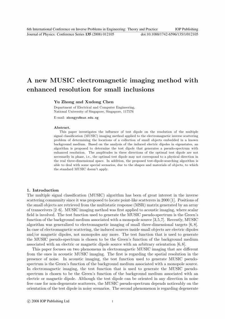
Figure 1 Singular values and pseudo-spectrum obtained by the standard MUSICalgorithm in noise free case (a) The 10 baselogarithm of the singular values of the MSRmatrix (j = 1 2 48) (b) (c) and (d) arethe 10 base logarithm of the pseudo-spectrumin y = x + 0112λ plane obtained by thestandard MUSIC algorithm with test dipolesin x y and z directions respectively
Figure 2 Pseudo-spectrum obtained bythe proposed MUSIC algorithm in noise freecase (a) (b) (c) and (d) are the 10 baselogarithm of the pseudo-spectrum in y =x + 0112λ plane obtained by the proposedMUSIC algorithm corresponding to the L =4 5 6 and 7 cases respectively
6th International Conference on Inverse Problems in Engineering Theory and Practice IOP PublishingJournal of Physics Conference Series 135 (2008) 012105 doi1010881742-65961351012105
5
the centers of spheres is 0255λ (the distance between the second and the third one) and forthe convenience of depiction of the test results all three spheres are chosen to locate in they = x + 0112λ plane Note that from the constitutive parameters of the scatterers there areup to eight independent secondary sources induced inside the three scatterers
There are 16 antenna units employed in this simulation half of which are aligned along the yaxis while the other half aligned along the z axis in the x = minus13λ plane The two linear arraysare centered at (minus13λminus9λ 11λ) with 5λ separation distance between neighboring units
For the noise free case the MSR matrix is calculated by (1) under the aforementionedcircumstance The singular values of the MSR matrix are shown in Fig1(a) in which we seethat the first eight singular values are much larger than the rest since they are correspondingto the eight singular vectors spanning the signal space Fig1(b) Fig1(c) and Fig1(d) are thepseudo-spectrum in y = x+0112λ plane obtained by the standard MUSIC method using x- y-and z-oriented test dipole respectively Not surprisingly the standard MUSIC algorithm canonly find the first two isotropic spheres and fail to locate the third degenerate anisotropic targetHere since the pseudo-spectrum value is too large at the positions of the scatterers we plot thebase 10 logarithm of it and the horizontal and vertical axes in Fig1(b) Fig1(c) and Fig1(d)are the x and z coordinate of spatial points in y = x+ 0112λ plane so do the cases hereafterBy using (11) the pseudo-spectrum obtained by the proposed MUSIC algorithm are shown inFig2 with L = 4 5 6 and 7 From these results we see that to locate the first two isotropicspheres we only need L = 6 but to locate the third degenerate anisotropic sphere we need
Figure 3 Pseudo-spectrum obtained bythe proposed MUSIC algorithm in noise freecase when the test dipole is constrained tobe real (a) (b) (c) (d) (e) and (f) arethe 10 base logarithm of the pseudo-spectrumin y = x + 0112λ plane obtained by theproposed MUSIC algorithm corresponding tothe L = 4 5 6 7 8 and 9 cases respectively
Figure 4 Singular values and pseudo-spectrum obtained by the standard MUSICalgorithm in noise-contaminated case (30dB)(a) The 10 base logarithm of the singularvalues of the MSR matrix (j = 1 2 48)(b) (c) and (d) are the pseudo-spectrum iny = x+0112λ plane obtained by the standardMUSIC algorithm with test dipoles in x yand z directions respectively
6th International Conference on Inverse Problems in Engineering Theory and Practice IOP PublishingJournal of Physics Conference Series 135 (2008) 012105 doi1010881742-65961351012105
6
L = 7 This is due to the reason that when locating one of the first two isotropic spheres therest two spheres have only five independent induced dipoles which means that L = 6 is sufficientfor (9b) to have exact solutions but if we want to locate the third degenerate sphere the resttwo isotropic spheres have totally six independent induced dipoles thus only when L = 7 canwe solve (9b) For the L = 4 and 5 cases since the L is not large enough to solve (9b) noneof the three scatterers can be located precisely If L is further increased to 8 and 9 the resultwill be almost the same as the one in L = 7 case which are not presented here If we constrainthe test dipole to be real ie a in (10) and (11) is real the pseudo-spectrum is shown in Fig3We see that L needs to be larger in order to locate the scatterers ie to locate the first twoisotropic spheres L need to be at least 7 while to locate the third degenerate sphere L at least8 Such a phenomenon was expected based on the analysis in the previous section
For the noise-contaminated case we add additive white Gaussian noise to the MSR matrix
The noise level is quantified by the signal to noise ratio (SNR) in dB defined as 20 log10 macrKmacrκ
where macrκ is the additive white Gaussian noise and middot denotes the Frobenius norm of a matrix [2][8] In this simulation 30dB white Gaussian noise is added Fig4(a) shows the singular valuesof the noise-contaminated MSR matrix in which the singular values corresponding to the noisespace are much larger than those in the noise free case In such a case if we apply the standardMUSIC algorithm to locate the scatterers the pseudo-spectrum obtained by the test dipolesin x y and z direction are shown in Fig4(b) Fig4(c) and Fig4(d) respectively which showthat all the three test dipole directions fail to locate any of the three scatterers By using the
Figure 5 Pseudo-spectrum obtained bythe proposed MUSIC algorithm in noise-contaminated case (30dB) (a) (b) (c) (d)(e) and (f) are the pseudo-spectrum in y =x + 0112λ plane obtained by the proposedMUSIC algorithm corresponding to the L =4 5 6 7 8 and 9 cases respectively
Figure 6 Pseudo-spectrum obtained bythe proposed MUSIC algorithm in noise-contaminated case (30dB) when the testdipole is constrained to be real (a) (b)(c) (d) (e) and (f) are the pseudo-spectrumin y = x + 0112λ plane obtained by theproposed MUSIC algorithm corresponding tothe L = 4 5 6 7 8 and 9 cases respectively
6th International Conference on Inverse Problems in Engineering Theory and Practice IOP PublishingJournal of Physics Conference Series 135 (2008) 012105 doi1010881742-65961351012105
7
proposed MUSIC algorithm the pseudo-spectrum are drawn in Fig5 In Fig5 for the L = 45 6 and 7 cases similar results can be observed as in Fig2 however for the L = 8 and 9 casessome unwanted disturbance appear in between the second and the third spheres which showsthat the singular vector corresponding to the eighth singular value is contaminated by the noiseto an extent so that it cannot be regarded as in the signal space anymore We further constrainthe test dipole to be real and obtain the results shown in Fig6 from which we clearly see thatthe third sphere cannot be located precisely This result could also be predicted from the resultsshown in Fig3 and Fig5 From Fig3 we know that to locate the third degenerate case weneed the information from the singular vector corresponding to the eighth singular value whichhowever has be moderately contaminated by noise according to the result shown in Fig5
5 Conclusion
A MUSIC algorithm with choosing the optimal test dipole direction has been proposed in thispaper which not only obtains a better resolution than the standard MUSIC algorithm does butalso is able to deal with the degenerate scatterers Based on the analysis of the eigenstate of theMSR matrix the proposed MUSIC algorithm determines the test dipole direction so that thecorresponding Greenrsquos function vector is in the space spanned by the dominant eigenvectors ofthe MSR matrix In addition the three components of the optimal test dipole are not necessarilyin phase ie the optimal test dipole may not correspond to a physical direction in real three-dimensional space The proposed algorithm was tested through numerical simulations Such analgorithm is a good candidate imaging method in situations where partial-aspected low SNRdata are collected
References[1] A J Devaney ldquoSuper-resolution processing of multi-static data using time-reversal and MUSICrdquo available
at httpwwweceneuedufacultydevaneyajdpreprintshtm 2000[2] Devaney A J 2005 IEEE Trans Antennas Propag 53 1600[3] Devaney A J Marengo E A and Gruber F K 2005 J Acoust Soc Am 118 3129[4] Simonetti F 2006 Phys Rev E 73 036619[5] Kirsch A 2002 Inverse Probl 18 1025[6] Ammari H Iakovleva E Lesselier D and Perruson G 2007 SIAM Sci Comput 29 674[7] Cheney M 2001 Inverse Probl 17 591[8] Zhong Y and Chen X 2007 IEEE Trans Antennas Propag 55 3542[9] Chen X and Agarwal K 2007 accepted by IEEE Trans Antennas Propag
[10] Chen X and Zhong Y 2007 Inverse Problem submitted[11] Bohren C F and Huffman D R 1998 Absorption and Scattering of Light by Small Particles (Berlin Wiley)[12] Ammari H and Kang H 2004 Reconstruction of Small Inhomogeneities from Boundary Measurements (Berlin
Springer-Verlag)[13] Kong J A 2000 Electromagnetic Wave Theory (Cambridge MA EMW)[14] Horn A and Johnson C R 1986 Matrix Analysis (Cambridge UK Cambridge University Press)
6th International Conference on Inverse Problems in Engineering Theory and Practice IOP PublishingJournal of Physics Conference Series 135 (2008) 012105 doi1010881742-65961351012105
8
scatterers in which only one or two independent components of an electric or magnetic dipoleare induced inside some small scatterers due to special shapes or composing materials of thescatterers For example a needle-like or disk-like small object may present only one or twodominant components of induced electric dipoles For an anisotropic small sphere when somecomponents in the principal axes of its permittivity tensor are equal to the permittivity ofthe background medium the number of independent electric dipole components are less thanthree In degenerate cases standard MUSIC algorithms [68] do not work because an arbitrarilychosen direction of test dipole is not necessarily located in the space spanned by actually inducedindependent dipole components
The choice of the test dipole direction has been investigated in [9 10] in two and threedimensional cases respectively to deal with degenerate scatterers However to the best ofour knowledge the effect of the choosing test dipole direction on the resolution of imaginghas not been investigated In this paper we propose an algorithm to obtain the directionof the test dipole that yields enhanced resolution and it can also deal with degenerate casesCompared with the previous MUSIC algorithms [68ndash10] that search for the test dipole directionso that the corresponding Greenrsquos function vector is orthogonal to the noise space that is theorthogonal complement to the range of the MSR matrix the proposed algorithm determines thetest dipole direction so that the corresponding Greenrsquos function vector is in the space spannedby the dominant eigenvectors of the MSR matrix Analysis of the induced electric dipoles ineigenstates provides the physical insight of the proposed method Theoretical and numericalresults show that three components of the optimal test dipole are not necessarily in phase iethe optimal test dipole may not correspond to a physical direction in the real three-dimensionalspace The proposed algorithm was tested through numerical simulations and was found to notonly provide better resolution than the standard MUSIC algorithm but also work well in thepresence of degenerate objects
2 Forward scattering problem
Consider M three-dimensional objects that are illuminated by time-harmonic electromagneticwaves radiated by an array of N antenna units The antenna units are located at rprime1 r
prime2 r
primeN
and each consists of 3 small dipole antennas oriented in the x y and z direction with the samelength l and driving current Iix Iiy Iiz respectively i = 1 2 N The M scatterers canbe of any shape but we consider only spherical or ellipsoidal objects in this paper for ease ofpresenting The size of each scatterer is much smaller than the wavelength so that Rayleighscattering occurs The centers of the scatterers are located at r1 r2 rM The scatterers aremade of isotropic or anisotropic materials The shape and composing material of each smallscatterer determine its polarization tenor macrξj [11 12] which relates the induced electric current
dipole Il(rj) inside the object to the total incident electric field Eint (rj) by Il(rj) = macrξj middotE
int (rj)
j = 1 2 M Expressions for macrξj for isotropic and anisotropic spheres and ellipsoids can befound in Ref [11] In this paper we assume all scatterers are non-magnetic and the backgroundmedium is free space
By using the Foldy-Lax equation the multi-static response (MSR) matrix that relatesscattered fields to driving current dipoles is given by [8 10]
identity matrix micro0 is the permeability of free space and macrΦ(j jprime) is null for j = jprime or is
imicro0macrG0(rj rjprime) for j 6= jprime with macrG0(r r
prime) being the dyadic Greenrsquos function in free space [13]The MSR matrix is characteristic of the collection of scatterers for given sets of transceivers atthe frequency of operation
6th International Conference on Inverse Problems in Engineering Theory and Practice IOP PublishingJournal of Physics Conference Series 135 (2008) 012105 doi1010881742-65961351012105
2
3 The MUSIC algorithm
31 Standard MUSIC algorithm
The MSR matrix macrK maps C3N the vector space of complex 3N -tuples to its range Sr sube C3N From the singular value decomposition (SVD) analysis [14] the MSR matrix could be represented
as macrK middot vp = σpup and macrKlowastmiddot up = σpvp p = 1 2 3N where the superscript lowast denotes
the Hermitian The vector space C3N can be decomposed into the direct sum of the rangeSr = spanup σp gt 0 and the orthogonal complement space Sn = spanup σp = 0 that isreferred to as noise space Consider non-degenerate scatterers in the absence of noise threeindependent electric current dipole components are induced in each scatterer and the scatteredfield Es is in the space S0 spanned by the background Greenrsquos function vectors associated withthe x y and z components of electric dipoles evaluated at the position of each scatterer ieEs isin S0 = span
Gx(rj) Gy(rj) Gz(rj) j = 1 2 M
where Gx(rj) Gy(rj) and Gz(rj)
are the [3(j minus 1) + 1]th [3(j minus 1) + 2]th and [3(j minus 1) + 3]th column of matrix macrR respectivelyGreenrsquos function vector Gl(r) l = x y z evaluated at an arbitrary position r can be definedsimilarly In this case it is easy to conclude that two subspaces Sr and S0 are identical [238]Due to the orthogonality between the range Sr and the noise space Sn we have
∣
∣ulowastpGl(rm)∣
∣ = 0and for σp = 0 m = 1 2 M and l = x y z The standard MUSIC algorithm [6 8] definesthe following pseudo-spectrum
Φ(r) =1
sum
σp=0
∣
∣ulowastpf(r)∣
∣
2 (2)
where test function f(r) can be any linear combination of Gx(r) Gy(r) and Gz(r) Thispseudo-spectrum becomes infinite at the position of every scatterer
32 MUSIC algorithm with the optimal test dipole direction
In degenerate cases however since the independent electric dipoles induced in a degeneratescatterer is less than three an arbitrarily chosen direction of test dipole is not necessarily locatedin the space spanned by actually induced independent dipole components Thus the standardMUSIC algorithm may fail to detect the degenerate scatterer [10] In addition even if there isno degenerate scatterers when scattered fields are noise contaminated the performance of theMUSIC algorithm is found to noticeably depend on the orientation of the test dipole
To find the optimal test dipole direction it is equivalent to determine a isin C3 subject to
||a|| = 1 so that the solution x to the equation
macrK middot x = macrG(r) middot a (3)
is most robust in the presence of noise where macrG(r) = [Gx(r) Gy(r) Gz(r)] The SVD of macrK isgiven by
macrK =
3Nsum
i=1
uiσivlowasti (4)
Assume eigenvalues are in non-increasing order σ1 ge σ2 ge ge σ3N ge 0 The least squaressolution of x is given by
x =3Nsum
i=1
ulowasti middotmacrG(r) middot a
σi
vi (5)
Note that the value of 1σi
is large for a small σi To obtain a stable solution x we should find a
so that ulowasti middotmacrG(r) middot a is non-zero for only the first few items Due to the orthogonality of ui we
6th International Conference on Inverse Problems in Engineering Theory and Practice IOP PublishingJournal of Physics Conference Series 135 (2008) 012105 doi1010881742-65961351012105
3
need to find a so that macrG(r) middot a is a linear combination of the first few ui
Lsum
i=1
λiui = macrG(r) middot a (6)
The proposed MUSIC algorithm is based on the analysis of the induced electric currentdipoles in the eigenstate which is referred to as the eigen-dipole hereafter Assume that the
current in the jth scatterer in the ith eigen-state is equal to J(i)j We have
ui =Msum
j=1
macrG(rj) middot J(i)j i = 1 2 L (7)
In the absence of noise (7) is exactly hold whereas in the presence of noise the quantities inthe left is approximately equal to that of the right and their difference is equal to the noise Thesubstitution of (7) into (6) yields
Msum
j=1
macrG(rj) middot
Lsum
i=1
λiJ(i)j = macrG(r) middot a (8)
There are two cases to be considered (a) when the test position r is not at any of the scatterersrj and (b) r is at one of the scatterers
Note that the Greenrsquos function vector macrG(r) are linearly independent to each other [5 6]When the test position r is not at any of the scatterers (8) is hold only when a = 0 and λi = 0
Therefore for any dipole direction a which satisfies ||a|| = 1 ulowasti middotmacrG(r) middot a is not equal to zero
for all 3N left singular vectors ui In this case the solution x is the linear combination of all3N right eigenvectors vi as shown in (5) The norm of x is large and it is not stable due to thepresence of small σi
When r is at one of the scatterers for example r = r1 (8) requires
Lsum
i=1
J(i)1 λi = a (9a)
Lsum
i=1
J(i)j λi = 0 j = 2 3 M (9b)
Eq (9b) amounts to determining the minimum value of L so that J (1) J (2) J (L) are linearly
dependent where J (i) is a column vector of length 3(M minus 1) consisting of J(i)j j = 2 3 M
Therefor when the test point r is at one of the scatterers the value of minimum L is equalto one plus the total number of independent dipoles induced in other scatterers For examplefor M isotropic spheres the value of L equals to 3M minus 2 It is stressed that the algorithmalso applies to degenerate cases When the nontrivial λi i = 1 2 L obtained from (9b) areplugged into (9a) the resulting a is generally a complex value When we force the vector a tobe real more eigen-states are needed to solve (9b) Thus from (5) we know that the solution isnot as robust as the one obtained from the previous complex a
An empirical approach to determine the approximate value of L is to find the total number ofdominant singular values from the spectrum The test dipole direction is determined by findinga isin C
3 subject to ||a|| = 1 so that macrG(r) middota is close to the space spanned by the first L dominant
6th International Conference on Inverse Problems in Engineering Theory and Practice IOP PublishingJournal of Physics Conference Series 135 (2008) 012105 doi1010881742-65961351012105
4
eigenvectors ui ie we aim at a minimum projection angle between the vector macrG(r) middot a and thespace spanned by the eigenvectors ui i = 1 2 L
a = arg maxa
sumLi=1 |u
lowasti middot
macrG(r) middot a|2
| macrG(r) middot a|2(10)
From the general eigenvalue decomposition we obtained the solution a that isgiven by the eigenvector corresponding to the maximum eigenvalue of the matrix(
macrG(r)lowast middot macrG(r))minus1 ([
macrU middot macrG(r)]lowast [
macrU middot macrG(r)])
where macrU = [u1 u2 uL]lowast Then the pseudo-
spectrum can be defined as
Φ(r) =1
1 minussumL
i=1|ulowast
imiddot macrG(r)middotamax|2
| macrG(r)middotamax|2
(11)
where amax is the optimal direction obtained by (10)
4 Numerical simulation
The inversion method proposed in previous section is tested through numerical simulations intwo scenarios noise free case and noise-contaminated case
We assume that three small spheres are located at r1 = (0084λ 0196λ 0084λ) r2 =(minus0168λminus0056λminus0112λ) and r3 = (minus0196λminus0084λ 0140λ) the first two of which areisotropic spheres with permittivity ǫ1 = ǫ2 = 2ǫ0 while the third is a rotated anisotropicsphere with permittivity tensor macrǫ3 = diag [ǫ0 3ǫ0 9ǫ0] and rotation Euler angles [8] (ψ φ θ) =(π4 π3 3π8) Here ǫ0 is the permittivity of the background free space These three spheresare electrically small with the same radius a = λ30 Note that the smallest distance between
Figure 1 Singular values and pseudo-spectrum obtained by the standard MUSICalgorithm in noise free case (a) The 10 baselogarithm of the singular values of the MSRmatrix (j = 1 2 48) (b) (c) and (d) arethe 10 base logarithm of the pseudo-spectrumin y = x + 0112λ plane obtained by thestandard MUSIC algorithm with test dipolesin x y and z directions respectively
Figure 2 Pseudo-spectrum obtained bythe proposed MUSIC algorithm in noise freecase (a) (b) (c) and (d) are the 10 baselogarithm of the pseudo-spectrum in y =x + 0112λ plane obtained by the proposedMUSIC algorithm corresponding to the L =4 5 6 and 7 cases respectively
6th International Conference on Inverse Problems in Engineering Theory and Practice IOP PublishingJournal of Physics Conference Series 135 (2008) 012105 doi1010881742-65961351012105
5
the centers of spheres is 0255λ (the distance between the second and the third one) and forthe convenience of depiction of the test results all three spheres are chosen to locate in they = x + 0112λ plane Note that from the constitutive parameters of the scatterers there areup to eight independent secondary sources induced inside the three scatterers
There are 16 antenna units employed in this simulation half of which are aligned along the yaxis while the other half aligned along the z axis in the x = minus13λ plane The two linear arraysare centered at (minus13λminus9λ 11λ) with 5λ separation distance between neighboring units
For the noise free case the MSR matrix is calculated by (1) under the aforementionedcircumstance The singular values of the MSR matrix are shown in Fig1(a) in which we seethat the first eight singular values are much larger than the rest since they are correspondingto the eight singular vectors spanning the signal space Fig1(b) Fig1(c) and Fig1(d) are thepseudo-spectrum in y = x+0112λ plane obtained by the standard MUSIC method using x- y-and z-oriented test dipole respectively Not surprisingly the standard MUSIC algorithm canonly find the first two isotropic spheres and fail to locate the third degenerate anisotropic targetHere since the pseudo-spectrum value is too large at the positions of the scatterers we plot thebase 10 logarithm of it and the horizontal and vertical axes in Fig1(b) Fig1(c) and Fig1(d)are the x and z coordinate of spatial points in y = x+ 0112λ plane so do the cases hereafterBy using (11) the pseudo-spectrum obtained by the proposed MUSIC algorithm are shown inFig2 with L = 4 5 6 and 7 From these results we see that to locate the first two isotropicspheres we only need L = 6 but to locate the third degenerate anisotropic sphere we need
Figure 3 Pseudo-spectrum obtained bythe proposed MUSIC algorithm in noise freecase when the test dipole is constrained tobe real (a) (b) (c) (d) (e) and (f) arethe 10 base logarithm of the pseudo-spectrumin y = x + 0112λ plane obtained by theproposed MUSIC algorithm corresponding tothe L = 4 5 6 7 8 and 9 cases respectively
Figure 4 Singular values and pseudo-spectrum obtained by the standard MUSICalgorithm in noise-contaminated case (30dB)(a) The 10 base logarithm of the singularvalues of the MSR matrix (j = 1 2 48)(b) (c) and (d) are the pseudo-spectrum iny = x+0112λ plane obtained by the standardMUSIC algorithm with test dipoles in x yand z directions respectively
6th International Conference on Inverse Problems in Engineering Theory and Practice IOP PublishingJournal of Physics Conference Series 135 (2008) 012105 doi1010881742-65961351012105
6
L = 7 This is due to the reason that when locating one of the first two isotropic spheres therest two spheres have only five independent induced dipoles which means that L = 6 is sufficientfor (9b) to have exact solutions but if we want to locate the third degenerate sphere the resttwo isotropic spheres have totally six independent induced dipoles thus only when L = 7 canwe solve (9b) For the L = 4 and 5 cases since the L is not large enough to solve (9b) noneof the three scatterers can be located precisely If L is further increased to 8 and 9 the resultwill be almost the same as the one in L = 7 case which are not presented here If we constrainthe test dipole to be real ie a in (10) and (11) is real the pseudo-spectrum is shown in Fig3We see that L needs to be larger in order to locate the scatterers ie to locate the first twoisotropic spheres L need to be at least 7 while to locate the third degenerate sphere L at least8 Such a phenomenon was expected based on the analysis in the previous section
For the noise-contaminated case we add additive white Gaussian noise to the MSR matrix
The noise level is quantified by the signal to noise ratio (SNR) in dB defined as 20 log10 macrKmacrκ
where macrκ is the additive white Gaussian noise and middot denotes the Frobenius norm of a matrix [2][8] In this simulation 30dB white Gaussian noise is added Fig4(a) shows the singular valuesof the noise-contaminated MSR matrix in which the singular values corresponding to the noisespace are much larger than those in the noise free case In such a case if we apply the standardMUSIC algorithm to locate the scatterers the pseudo-spectrum obtained by the test dipolesin x y and z direction are shown in Fig4(b) Fig4(c) and Fig4(d) respectively which showthat all the three test dipole directions fail to locate any of the three scatterers By using the
Figure 5 Pseudo-spectrum obtained bythe proposed MUSIC algorithm in noise-contaminated case (30dB) (a) (b) (c) (d)(e) and (f) are the pseudo-spectrum in y =x + 0112λ plane obtained by the proposedMUSIC algorithm corresponding to the L =4 5 6 7 8 and 9 cases respectively
Figure 6 Pseudo-spectrum obtained bythe proposed MUSIC algorithm in noise-contaminated case (30dB) when the testdipole is constrained to be real (a) (b)(c) (d) (e) and (f) are the pseudo-spectrumin y = x + 0112λ plane obtained by theproposed MUSIC algorithm corresponding tothe L = 4 5 6 7 8 and 9 cases respectively
6th International Conference on Inverse Problems in Engineering Theory and Practice IOP PublishingJournal of Physics Conference Series 135 (2008) 012105 doi1010881742-65961351012105
7
proposed MUSIC algorithm the pseudo-spectrum are drawn in Fig5 In Fig5 for the L = 45 6 and 7 cases similar results can be observed as in Fig2 however for the L = 8 and 9 casessome unwanted disturbance appear in between the second and the third spheres which showsthat the singular vector corresponding to the eighth singular value is contaminated by the noiseto an extent so that it cannot be regarded as in the signal space anymore We further constrainthe test dipole to be real and obtain the results shown in Fig6 from which we clearly see thatthe third sphere cannot be located precisely This result could also be predicted from the resultsshown in Fig3 and Fig5 From Fig3 we know that to locate the third degenerate case weneed the information from the singular vector corresponding to the eighth singular value whichhowever has be moderately contaminated by noise according to the result shown in Fig5
5 Conclusion
A MUSIC algorithm with choosing the optimal test dipole direction has been proposed in thispaper which not only obtains a better resolution than the standard MUSIC algorithm does butalso is able to deal with the degenerate scatterers Based on the analysis of the eigenstate of theMSR matrix the proposed MUSIC algorithm determines the test dipole direction so that thecorresponding Greenrsquos function vector is in the space spanned by the dominant eigenvectors ofthe MSR matrix In addition the three components of the optimal test dipole are not necessarilyin phase ie the optimal test dipole may not correspond to a physical direction in real three-dimensional space The proposed algorithm was tested through numerical simulations Such analgorithm is a good candidate imaging method in situations where partial-aspected low SNRdata are collected
References[1] A J Devaney ldquoSuper-resolution processing of multi-static data using time-reversal and MUSICrdquo available
at httpwwweceneuedufacultydevaneyajdpreprintshtm 2000[2] Devaney A J 2005 IEEE Trans Antennas Propag 53 1600[3] Devaney A J Marengo E A and Gruber F K 2005 J Acoust Soc Am 118 3129[4] Simonetti F 2006 Phys Rev E 73 036619[5] Kirsch A 2002 Inverse Probl 18 1025[6] Ammari H Iakovleva E Lesselier D and Perruson G 2007 SIAM Sci Comput 29 674[7] Cheney M 2001 Inverse Probl 17 591[8] Zhong Y and Chen X 2007 IEEE Trans Antennas Propag 55 3542[9] Chen X and Agarwal K 2007 accepted by IEEE Trans Antennas Propag
[10] Chen X and Zhong Y 2007 Inverse Problem submitted[11] Bohren C F and Huffman D R 1998 Absorption and Scattering of Light by Small Particles (Berlin Wiley)[12] Ammari H and Kang H 2004 Reconstruction of Small Inhomogeneities from Boundary Measurements (Berlin
Springer-Verlag)[13] Kong J A 2000 Electromagnetic Wave Theory (Cambridge MA EMW)[14] Horn A and Johnson C R 1986 Matrix Analysis (Cambridge UK Cambridge University Press)
6th International Conference on Inverse Problems in Engineering Theory and Practice IOP PublishingJournal of Physics Conference Series 135 (2008) 012105 doi1010881742-65961351012105
8
proposed MUSIC algorithm the pseudo-spectrum are drawn in Fig5 In Fig5 for the L = 45 6 and 7 cases similar results can be observed as in Fig2 however for the L = 8 and 9 casessome unwanted disturbance appear in between the second and the third spheres which showsthat the singular vector corresponding to the eighth singular value is contaminated by the noiseto an extent so that it cannot be regarded as in the signal space anymore We further constrainthe test dipole to be real and obtain the results shown in Fig6 from which we clearly see thatthe third sphere cannot be located precisely This result could also be predicted from the resultsshown in Fig3 and Fig5 From Fig3 we know that to locate the third degenerate case weneed the information from the singular vector corresponding to the eighth singular value whichhowever has be moderately contaminated by noise according to the result shown in Fig5
5 Conclusion
A MUSIC algorithm with choosing the optimal test dipole direction has been proposed in thispaper which not only obtains a better resolution than the standard MUSIC algorithm does butalso is able to deal with the degenerate scatterers Based on the analysis of the eigenstate of theMSR matrix the proposed MUSIC algorithm determines the test dipole direction so that thecorresponding Greenrsquos function vector is in the space spanned by the dominant eigenvectors ofthe MSR matrix In addition the three components of the optimal test dipole are not necessarilyin phase ie the optimal test dipole may not correspond to a physical direction in real three-dimensional space The proposed algorithm was tested through numerical simulations Such analgorithm is a good candidate imaging method in situations where partial-aspected low SNRdata are collected
References[1] A J Devaney ldquoSuper-resolution processing of multi-static data using time-reversal and MUSICrdquo available
at httpwwweceneuedufacultydevaneyajdpreprintshtm 2000[2] Devaney A J 2005 IEEE Trans Antennas Propag 53 1600[3] Devaney A J Marengo E A and Gruber F K 2005 J Acoust Soc Am 118 3129[4] Simonetti F 2006 Phys Rev E 73 036619[5] Kirsch A 2002 Inverse Probl 18 1025[6] Ammari H Iakovleva E Lesselier D and Perruson G 2007 SIAM Sci Comput 29 674[7] Cheney M 2001 Inverse Probl 17 591[8] Zhong Y and Chen X 2007 IEEE Trans Antennas Propag 55 3542[9] Chen X and Agarwal K 2007 accepted by IEEE Trans Antennas Propag
[10] Chen X and Zhong Y 2007 Inverse Problem submitted[11] Bohren C F and Huffman D R 1998 Absorption and Scattering of Light by Small Particles (Berlin Wiley)[12] Ammari H and Kang H 2004 Reconstruction of Small Inhomogeneities from Boundary Measurements (Berlin
Springer-Verlag)[13] Kong J A 2000 Electromagnetic Wave Theory (Cambridge MA EMW)[14] Horn A and Johnson C R 1986 Matrix Analysis (Cambridge UK Cambridge University Press)
6th International Conference on Inverse Problems in Engineering Theory and Practice IOP PublishingJournal of Physics Conference Series 135 (2008) 012105 doi1010881742-65961351012105