Indian Journal of Fibre & Textile Research Vol. 17 , December 1992, pp. 209-214 A new ring-and-traveller system as the key to more production from the ring spinning machine H Stalder Rieter Spinning Systems , Maschinenfabrik Rieter AG, CH-8406 Winterthur, Switzerland Received 30 March 1992 Due to high surface pressure between ring and traveller the thermal load capacity of the traveller is the key element for the limitation of the traveller speed and therefore the productivity of the ring frame. Reduction of the surface pressure is therefore a main goal in the ring/traveller development. In this pa- per, the new ORBIT ring/traveller system with a much lower surface pressure between ring and traveller is described. This system, accordingly, allows considerably higher traveller speeds. It furthermore re- duces the danger of damaging the yarn when spinning man-made fibres, which makes it possible to spin even man-made fibre at higher spindle speeds. Keywords: Oblique flange ring, ORBIT ring/traveller system, Ring spinning, Yarn damage 1 The Problem Faced It was rightly pointed out l recently that the ring- and-traveller system is a crucial element in the ef- forts to raise production on the ring spinning ma- chine. True, but besides this system there ate other elements in ring spinning which can place limit- ations in the path of productivity advances, such as the yarn stressing between drafting system and cop or the danger of yarn damage due to friction on the guiding elements. Nevertheless, in practice, the ring/ traveller system is the most common limiting factor. In the article mentioned, possibilities were indicated accordingly for achieving the highest production rates possible with the familiar T-section rings. Fur- ther to this, the present article will now describe how still more production gains are made possible by a new ring/traveller system. To maintain the stability of the spinning balloon, the ring/traveller system must ensure that the yarn tension 5 reaches a certain level. This value may be expressed as follows I: 2 VL sin a d R where is the coefficient of friction between ring and traveller; the traveller mass; a, the angle be- tween yarn from traveller to cop and straight line from traveller to spindle axis; V L , the traveller speed; and dR, the ring diameter. By transforming the stated proportionality we ob- tain: _ 5- -.- ·Z sma where Z is the centrifugal force. In practice, the variables and a are given. Moreover, the centrifugal force Z acting on the tra- veller may be substituted in good approximation by the normal force N occurring between ring and tra- veller. Thus,5:::::N In other words, a certain normal force is needed between ring and traveller to stabilize the balloon. Of course, this normal force sets up a friction force, which, in turn, leads to generation of heat. If the spindle speed is raised, and with it the normal force N, sooner or later a point is reached at which the li- mit of the thermal load capacity of the ring/traveller system is reached. And so the limitation of ring spinning by the ring/traveller system is clearly ther- mal in nature. In the article referred to it is shown that to assess the thermal loading state of the ring/traveller system the surface pressure FP between ring and traveller may be taken as a measure (Fig. 1): N Z FP=-:::::- F F where F represents the contact surface between ring and traveller. It therefore follows: Zmax ::::: F· F P.:ril
Transcript
Indian Journal of Fibre & Textile Research Vol. 17, December 1992, pp. 209-214
A new ring-and-traveller system as the key to more production from the ring spinning machine
Due to high surface pressure between ring and traveller the thermal load capacity of the traveller is the key element for the limitation of the traveller speed and therefore the productivity of the ring frame. Reduction of the surface pressure is therefore a main goal in the ring/traveller development. In this paper, the new ORBIT ring/traveller system with a much lower surface pressure between ring and traveller is described. This system, accordingly, allows considerably higher traveller speeds. It furthermore reduces the danger of damaging the yarn when spinning man-made fibres , which makes it possible to spin even man-made fibre at higher spindle speeds.
1 The Problem Faced It was rightly pointed out l recently that the ring
and-traveller system is a crucial element in the efforts to raise production on the ring spinning machine. True, but besides this system there ate other elements in ring spinning which can place limitations in the path of productivity advances, such as the yarn stressing between drafting system and cop or the danger of yarn damage due to friction on the guiding elements. Nevertheless, in practice, the ring/ traveller system is the most common limiting factor. In the article mentioned, possibilities were indicated accordingly for achieving the highest production rates possible with the familiar T-section rings. Further to this, the present article will now describe how still more production gains are made possible by a new ring/traveller system.
To maintain the stability of the spinning balloon, the ring/traveller system must ensure that the yarn tension 5 reaches a certain level. This value may be expressed as follows I:
2 5:::::~.mL· V L
sin a dR
where ~L is the coefficient of friction between ring and traveller; ~, the traveller mass; a, the angle between yarn from traveller to cop and straight line from traveller to spindle axis; VL, the traveller speed; and dR, the ring diameter.
By transforming the stated proportionality we obtain:
_ ~L 5- - . - ·Z
sma
where Z is the centrifugal force. In practice, the variables ~L and a are given.
Moreover, the centrifugal force Z acting on the traveller may be substituted in good approximation by the normal force N occurring between ring and traveller.
Thus,5:::::N
In other words, a certain normal force is needed between ring and traveller to stabilize the balloon. Of course, this normal force sets up a friction force, which, in turn, leads to generation of heat. If the spindle speed is raised, and with it the normal force N, sooner or later a point is reached at which the limit of the thermal load capacity of the ring/traveller system is reached. And so the limitation of ring spinning by the ring/traveller system is clearly thermal in nature.
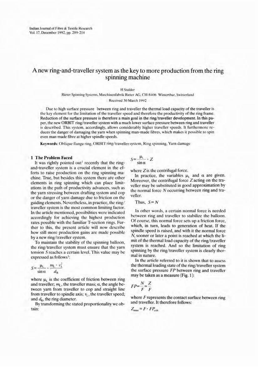
In the article referred to it is shown that to assess the thermal loading state of the ring/traveller system the surface pressure FP between ring and traveller may be taken as a measure (Fig. 1):
N Z FP=-:::::-
F F
where F represents the contact surface between ring and traveller. It therefore follows:
Zmax ::::: F· F P.:ril
210 INDlA'N J. FIBRE TEXT. RES .. DECEMBER 1992
0.7 -
L 0.6 -(Jl
E 0.5 -..... a (IJ 0.4 -1-------------/ 3 ~ 0.3 -1--------------1
~ 0.2 ------------1 a ..... t- 0.1 -I-----------_#..
Stable Phase
o -~, _==:::h==1::=~===
o Critical Surface pressurJ
Surface Pressure
Fig. l - Traveller wear in function"of the surface pressure
or with a given admissible surface pressure Fp.:rit :
Zma. "" F
m ''vi L t m """ F dR
It follows from this that increasing the contact surface between ring and traveller will make possible much higher traveller speeds.
2 The Oblique Flange Ring Concept If the T-flange ring shape is retained, it is virtually
impossible to increase the contact surface between ring and traveller. Consequently, sometime ago a search began for ring cross-sections that would allow this and these efforts were crowned with success in the early 1960s, when Russian development people introduced the so-called SU ring. This oblique flange ring is in fact able to satisfy the demand for more contact surface between ring and traveller (Fig. 2), providing about 4-5 times more surface than a T ring.
But besides their bigger contact surface, oblique flange rings have another advantage as well. For the same yarn tensions, i.e. same friction forces , with oblique flange rings the traveller weight may be reduced by 10-20% compared with T rings. In this way the loading of the ring/traveller system is lowered still further , or the speed potential of the traveller is raised further. The reason for this possibility of using lighter travellers with oblique flange rings lies in the geometry of the forces (Fig. 3). Because the traveller is in a steady state, the forces Z, 5 and N acting on it in the plane through the spindle axis form a closed triangle of forces . This triangle of
SU-Ring
Fig.2 - Systcrm of ring anu traveller
S - Yarn Tension N - Normal Force between
Ring and Traveller Z - Centrifugal Force
Fig.3- Forccs acting on the traveller in the plane of tht: traveller/ spindle axi~
forces is of general validity for given balloon conditions, i.e. in particular it is independent of the ring! traveller system employed. With the T ring there is only single normal force N between ring and traveller, whereas with the oblique flange ring this force is divided into two components N) and N2• Vectorwise the sum of N) and N2 is equal to the force N:
N) +N2 = N
Scalarwise, however, the sum of N) and N2 exceeds N:
N) +N2 > N
Hence, for the friction forces caused by the normal forces:
/AN) + /A N2 > /AN
R) +R2 > R
i.e. under the same boundary conditions (in particular same traveller masses and same coefficients of
STALDER: A NEW RING-ANO-TRAVELLER SYSTEM 211
friction) an oblique flange traveller sets up higher friction forces than a T ring. Consequently, for the same yarn forces , lighter travellers may be used with oblique flange rings than with T rings.
The SU ring/traveller system offers two major advantages: - Significantly bigger contact surface between
ring and traveller. - The possibility of using lighter travellers.
Yet despite these advantages of T rings, SU rings have not really earned industrial acceptance. This is because the SU ring/traveller system brings not only benefits but also certain problems: - The contact surface F) between ring and travell
er available for absorbing the force N) is very large indeed. On the other hand, the corresponding surface Fl for force Nl on the top of the ring is very small. As a result, the surface pressure FPz in the range offorce Nz is much higher than the surface pressure FP) in the range of N) :
FR = N) ) F) F) very large
F2 small
This means that although the surface pressure FP1 is very much lower than with a T ring, the surface pressure FPz is not lower but higher even than with this. Consequently, the performance limit of the SU ring/traveller is, in practice, not higher than that of the conventional T ring system. From Fig. 2 it is clear that owing to the different ring cross-sections the wire length of the SU traveller is significantly greater than that of the C traveller. Thus, for the same mass, SU travellers have a smaller wire cross-section than C travellers. This difference is magnified further by the peculiarity of the oblique flange system already mentioned, i.e. lighter travellers are required than for the T ring system. Since, for various reasons, there is a limit to how thin traveller wires can be made, it follows that the SU ring system cannot be used for spinning fine yarns. With the SU ring system there is a danger of the yarn unthreading on the inside of the ring during stop-start operations on the ring spinning machine, due to its proneness to snarling. This property is manifested in varying degrees depending on the yarn and fibre types. Nevertheless, it has resulted in many cases in such severe
increases in the number of ends down whe.1 starting that the use of SU rings was impossible.
To sum up, the basic principle of the oblique flange ring is highly commendable, but its embodiment so far in the form of the SU ring is still far removed from the possible optimum.
3 The Rieter Oblique Flange System Orbit In view of this situation, Rieter Spinning Systems
decided to develop further this inherently attractive principle of the oblique flange ring, with the aim of overcoming the above problems associated with the familiar SU rings. This work on new oblique flange ring system was performed in close collaboration with Bracker AG, Pfaffikon and Prosino s.r.I., Borgosesia. By dint of this couperation between makers of ring-spinning machines, rings and travellers, the targets set for this development were achieved in full. A brief account now follows of the approaches which led to this significant success of the Rieter oblique flange system.
3.1 Spinnability of Fine Yarns
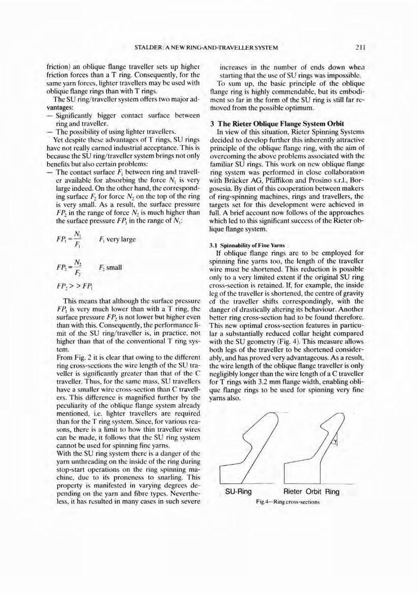
If oblique flange rings are to be employed for spinning fine yarns too, the length of the traveller wire must be shortened. This reduction is possible only to a very limited extent if the original SU ring cross-section is retained. If, for example, the inside leg of the traveller is shortened, the centre of gravity of the traveller shifts correspondingly, with the danger of drastically altering its behaviour. Another better ring cross-section had to be found therefore. This new optimal cross-section features in particular a substantially reduced collar height compared with the SU geometry (Fig. 4). This measure allows both legs of the traveller to be shortened considerably, and has proved very advantageous. As a result, the wire length of the oblique flange traveller is only negligibly longer than the wire length of a C traveller for T rings with 3.2 mm flange width, enabling oblique flange rings to be used for spinning very fine yarns also.
SU-Ring Rieter Orbit Ring Fig.4- Ring cross-sections
212 INDIAN J. FIBRE TEXT. RES., DECEMBER 1992
3.2 Reducing the Surface Pressure at the Top of the Ring
The division of the normal force N between ring and traveller into the two part forces Nl and N2 depends very much on the inclination of the conical ring surface. Therefore, to reduce the force N2 acting on the top of the' ring, the angle y (Fig. 4 ) was optimized accordingly. But only optimizing the angle is not sufficient to get an ideal ,distribution of the surface pressure. More detail provisions are required. Thanks to a systematic research on the Rieter Orbit Ring, the desired ideal surface pressure was realized.
3.3 Preventing Unthreading
With the SU ring there is a danger of the yarn unthreading from the traveller when the machine is stopped, because the inner leg is straight and open to the bottom. The torque present in the yarn may, therefore, cause the yarn to slip out of the traveller at the toe of the inside leg. Consequently, ways had to be found for depriving the yarn of this possibility, i.c. of preventing the yarn getting into the range of the inside traveller toe at all. To ensure this, a socalled supporting ring was evolved (Fig. 5 ). Unthreading is now ruled out, and with it the bugbear of virtually all of the end breaks at stop-start operations on the ring-spinning machine.
This supporting ring has revealed a secondary benefit as well. Comparative trials with and without it show that the formation of a load-bearing fibre lubrication film in the zone of the conical ring surface is noticeably accelerated by the supporting ring.
Spinning Ring Supporting Ring Fig.5-Rieter Orbit ring with integrated supporting ring
3.4 Optimizing the Ring Surface Since with the oblique flange ring system the sur
face pressure is less than with the conventional ring system, to obtain the best results the surfaces of the rings and travellers must of course be adapted to these changed boundary conditions. In particular, it must be ensured that the very important increase of the seizing resistance on the ring surface which takes place during running-in is encouraged. After protracted and intensive trials it has been possible to find a surface pairing for the oblique flange rings and travellers which meets these requirements in full. By a combination of the surface materials and the structures of these on the two friction partners it has been possible to shorten the running-in time of the rings perceptibly compared with ordinary rings , while at the same time assuring optimal performance after running-in. Furthermore, the characteristic colouring of the oblique flange rings and travellers assists finding the traveller when clearing end breaks manually.
3.5 Enlarging the Yarn Passage
The size of the yarn passage provided by a ring/ traveller system is a perennial subject for discussion, especially where man-made fibre spinning is concerned. With conventional T rings this passage is so confined that contact between yarn and ring surface cannot be avoided, especially if low-curving travellers with flat wire cross-section are employed. When spinning synthetic fibres , this leads to yarn damage resulting from melting points. Accordingly, when developing the oblique flange system, attention was given to obtaining as much space as possible for the yarn passage through the traveller. Ultra-fast exposures of the traveller rotating at full speed show clearly that this objective too has been achieved in full. The distinctly bigger yarn passage with the oblique flange system Orbit results from two circumstances:
With the oblique flange ring the ring surface diminishes strongly from the top of the ring towards the outside. Owing to the changed location of the force application points on the oblique flange traveller, the angle a on this traveller is only half as wide as on a conventional traveller.
Thus, when spinning fibres susceptible to damage, the oblique flange system offers additional advantages.
3.6 Results with the Rieter Oblique Flange System Orbit
As mentioned earlier, the thermal loading state of a ring/traveller system can be assessed very well from the amount of the surface pressure FP be-
STALDER: A NEW RING-AND-TRAVELLER SYSTEM 213
tween ring and traveller. Fig. 1 shows the corresponding relation between surface pressure and traveIJer wear for conventional T rings, with the curve kinked clearly in the critical surface pressure range. Assuming that the contact surface between ring and traveller remains constant, in the figure mentioned the surface pressure is taken to be proportional to the centrifugal force acting on the traveller:
Z Fp==:. -F
Therefore, with constant surface F: Fpz.Z
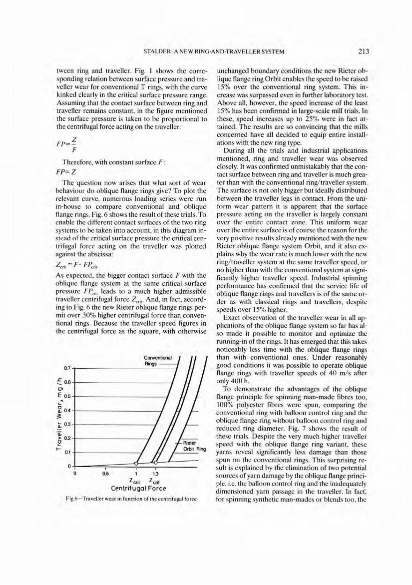
The question now arises that what sort of wear behaviour do oblique flange rings give? To plot the relevant curve, numerous loading series were run in-house to compare conventional and oblique flange rings. Fig. 6 shows the result of these trials. To enable the different contact surfaces of the two ring systems to be taken into account, in this diagram instead of the critical surface pressure the critical centrifugal force acting on the traveller was plotted against the abscissa:
Z crit ==:. F· F Pcrit
As expected, the bigger contact surface F with the oblique flange system at the same critical surface pressure FPcrit leads to a much higher admissible traveller centrifugal force Z crit. And, in fact, according to Fig. 6 the new Rieter oblique flange rings permit over 30% higher centrifugal force than conventional rings. Because the traveller speed figures in the centrifugal force as the square, with otherwise
Fig.6- Traveller wear in function of the centrifugal force
unchanged boundary conditions the new Rieter oblique flange ring Orbit enables the speed to be raised 15% over the conventional ring system. This increase was surpassed even in further laboratory test. Above all, however, the speed increase of the least 15% has been confirmed in large-scaie mill trials . In these, speed increases up to 25% were in fact attained. The results are so convincing that the mills concerned have all decided to equip entire installations with the new ring type.
During all the trials and industrial applications mentioned, ring and traveller wear was observed closely. It was confirmed unmistakably that the contact surface between ring and traveller is much greater than with the conventional ring/traveller system. The surface is not only bigger but ideally distributed between the traveller legs in contact. From the uniform wear pattern it is apparent that the surface pressure acting on the traveller is largely constant over the entire contact zone. This uniform wear over the entire surface is of course the reason for the very positive results already mentiOned with the new Rieter oblique flange system Orbit, and it also explains why the wear rate is much lower with the new ring/traveller system at the same traveller speed, or no higher than with the conventional system at significantly higher traveller speed. Industrial spinning performance has confirmed that the service life of oblique flange rings and travellers is of the same order as with classical rings and travellers, despite speeds over 15% higher.
Exact observation of the traveller wear in all applications of the oblique flange system so far has also made it possible to monitor and optimize the running-in of the rings. It has emerged that this takes noticeably less time with the oblique flange rings than with conventional ones. Under reasonably good conditions it was possible to operate oblique flange rings with traveller speeds of 40 ml s after only 400 h.
To demonstrate the advantages of the oblique flange principle for spinning man-made fibres too, 100% polyester fibres were spun, comparing the conventional ring with balloon control ring and the oblique flange ring without balloon control ring and reduced ring diameter. Fig. 7 shows the result of these trials. Despite thc very much higher traveller speed with the oblique flange ring variant, these yarns reveal significantly less damage than those spun on the conventional rings. This surprising result is explained by the elimination of two potential sources of yarn damage by the oblique flange principle, i.e. the balloon control ring and the inadequately dimensioned yarn passage in the traveller. In fact', for spinning synthetic man-mades or blends too, the
214 INDIAN 1. FIBRE TEXT. RES., DECEMBER 1992
100% PES: 1.1 dtex, 36 mm Ne 75
Traveller speed [mls) 34 42 I Ring diameter [mm) 45 38 1 Ring type T-Ring Orbitring I Balloon control ring with without I Traveller count ISO 50
Yarn damages
Fig. 7 - Rieter Orbit ring spinning tests
oblique flange concept opens up new possibilities for raising productivity.
For fitting oblique flange travellers on the rings without problems, there are of course the familiar Bracker-Rapid traveller appliances, in conjunction with the Bracker-Strap magazine system.
4 Summing-up and Prospects To ensure the stability of the spinning balloon, the
ring/traveller system must set up a certain spinning tension 5, which depends primarily on the traveller speed:
5"'" vl With yarns of low strength (e.g. soft-twisted
yarns), this yarn loading at higher speeds may lead to a steep rise in ends down. In such cases the productivity limit of the ring-spinning machine is determined by the yarn loading. In all other cases, however, the ring/traveller system itself is the productivity-limiting factor . A joint development by Bracker AG, Prosino s.r.I. and Rieter Spinning Systems has now made it possible to offer a new ring/traveller
system Orbit with significantly higher performance potential for these cases.
This new ring/traveller system (Patent pending) based on the oblique flange principle enables the traveller speed to be raised 15% or more compared with the orthodox T flange ring system, without sacrificing ring and traveller life. The known disadvantages of previous oblique flange rings have been eliminated completely by the new Rieter design, so that spinners now have a genuine high-performance ring/traveller system available with a wide application range. Besides notably higher traveller speeds the new Rieter ring system' offers further advantages when spinning man-made fibres, for the danger of yarn damage with this system is much less than with conventional T flange rings.
Needless to say, if the performance potential of this new high-performance ring/traveller Orbit system is to be fully exploited, there are a few conditions to be met-mostly of general validity: - The ring must be run-in properly. - After changing travellers it is advisable to carry
out a short traveller running-in programme. - Travellers must be changed before they are too
badly worn. - The lightest traveller weight possible must be
adopted . For oblique flange travellers and high speeds, the travellers should be at least three counts lighter than those recommended usually.
- The rings must be centered exactly. - On account of the high spindle speeds possible, it
is advisable to employ low-noise spindles.
With the new Rieter ring/traveller Orbit system it is possible to raise the performance limit to ring spinning by a further significant amount, enabling the machine to operate at spindle speeds yielding virtually optimal costs. In this way the yarn production costs of ring spinning can be cut still further, making it a really high-performance operation.
References I Stalder H , Melliand Textilber, 72 (1 99 1) 585.