Feature Report A New uonc%.pt in Structural Design for Mexico City Elevated Metro by Jose Ma. Rioboo Martin President Rioboo Consulting Engineers Mexico City, Mexico Also, Member of Mexico City Subcommittee on Design and Building Code. S inceAugust 1987, the Mexico City Metro (People's Rapid Transporta- tion System) has a new route in service. This is Line No. 9, whose eastern part runs 9 m (29.5 ft) above ground level. Mexico City Metro is now 153 km (95 miles) long. Since 1969, when the f'acil- ity first started operating, it has become one of the most economic, fastest and pollution-free transportation systems in the world. Today, the facility transports 5 million people per day. Metro Sys- tem comprises four different types of structural elements: tunnel, subway, street level and elevated structure. Construction of the system began in 1977, and since then it has gradually been enlarged to serve the ever growing urban population. Today, the population of Mexico City is about 18 million and by the year 2010 it is anticipated the city will grow to 34 million. These are stag- gering figures which only reflect the magnitude of the transportation problem. It has, therefore, been a continuing challenge to find simpler, more efficient and cost effective solutions with which to build such systems. The problem is compounded because of high inflation (resulting in tight budgets), over- crowded urban conditions, the suscep- tibility of strong earthquakes and the poor characteristics of Mexico City sub- soil. 112
Transcript
Feature Report
A New uonc%.pt inStructural Design for
Mexico City Elevated Metroby
Jose Ma. Rioboo MartinPresidentRioboo Consulting EngineersMexico City, MexicoAlso, Member of Mexico CitySubcommittee on Design andBuilding Code.
S inceAugust 1987, the Mexico CityMetro (People's Rapid Transporta-
tion System) has a new route in service.This is Line No. 9, whose eastern partruns 9 m (29.5 ft) above ground level.
Mexico City Metro is now 153 km (95miles) long. Since 1969, when the f'acil-ity first started operating, it has becomeone of the most economic, fastest andpollution-free transportation systems inthe world. Today, the facility transports5 million people per day. Metro Sys-tem comprises four different types ofstructural elements: tunnel, subway,street level and elevated structure.
Construction of the system began in1977, and since then it has gradually
been enlarged to serve the ever growingurban population. Today, the populationof Mexico City is about 18 million andby the year 2010 it is anticipated the citywill grow to 34 million. These are stag-gering figures which only reflect themagnitude of the transportation problem.
It has, therefore, been a continuingchallenge to find simpler, more efficientand cost effective solutions with whichto build such systems. The problem iscompounded because of high inflation(resulting in tight budgets), over-crowded urban conditions, the suscep-tibility of strong earthquakes and thepoor characteristics of Mexico City sub-soil.
112
The author describes the design and constructionfeatures of the new elevated line of Mexico City'sMetro. This 5.6 km (3.5 mile) long structure, withbeams spanning 40 m (131.23 ft), uses precastprestressed concrete extensively together withsome innovative structural design solutions.
The first structural design made for anelevated line of Mexico City Metro wasdone for Line No. 4 in 1982. This systemconsisted of simply supported post-ten-sioned box girders, cast-in-place, 35.0 m(114.83 ft) long, supported by very stoutcolumns. These columns were designedto resist, in cantilever, the entire seismicforce.
In 1987, a new elevated line wasbuilt; it is the eastern part of Line No. 9and consists of four passenger stations,five intermediate sections (betweenstations), and a warehouse for passengercars located at the end of the line (seeFig. 1).
It was decided to keep this portion of
Line No. 9 elevated because of the typeof underlying subsoil and the largenumber of street and freeway crossingsoccurring along it.
An innovative structural solution wasused for this line. The 5.6 km (3.5 mile)long structure was defined longitudi-nally by four main Gerber beams andtransversally by seven secondary beams,hereinafter referred to as diaphragms(see Fig. 2).
Each main beam is composed of acentral simply supported portion whichis located at the middle of the span andsupport beams that rest on the columnsof the substructure.
Both the central and support beams
PCI JQURNALJanuary- February 1988 113
N1
MEXICO CITYAIRPORT1
PANTITLAN TERMINAL.STATION CORRESPONDENCETO LINES NI AND N•5
Fig. 2. Elevation and typical cross section of Line No. 9.
rn114.83 t
SIMPLESUPPORTED BEAM
CAST IN PLACE787' 18.04'
POST- TENSIONED BEAMS
1_.o c aoaca nLine N° 4 (1982)
t, __ __ 131.23'
16.40 r
It4.83'
7.22 5 58'
CENTRAL BEAM SUPPORT
PRECAST PRETENSIONED BEAMS BEAM Z.62 18.04'
DOUBLE COLUMNS SYSTEM
Line N° 9 (1987)
rig. 3. tlevations 01 LineS No. 4 and No. 9.
ET1TfTTCAST IN PLACEPOST-TENSIONED BEAMS
Line N o 4 ( 1982 )
TOPPINGTi iii
PRECASTPRETENSIONED BEAMS
Line N° 9 (1987)
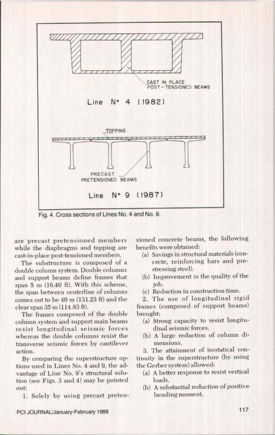
Fig. 4. Cross sections of Lines No. 4 and No. 9.
are precast pretensioned memberswhile the diaphragms and topping arecast-in-place post-tensioned members.
The substructure is composed of adouble column s ystem. Double columnsand support beams define frames thatspan 5 m (16.40 ft). With this scheme,the span between centerline of columnscomes out to be 40 m (131.23 ft) and theclear span 35 m (114.83 ft).
The frames composed of the doublecolumn system and support main beamsresist longitudinal seismic forceswhereas the double columns resist thetransverse seismic forces by cantileveraction.
By comparing the superstructure op-tions used in Lines No. 4 and 9, the ad-vantage of Line No. 9's structural solu-tion (see Figs. 3 and 4) may be pointedout:
1. Solely by using precast preten-
sioned concrete beams, the followingbenefits were obtained:
(a) Savings in structural materials (con-crete, reinforcing bars and pre-stressing steel).
(b) Improvement in the quality of thejob.
(c) Reduction in construction time.2. The use of longitudinal rigid
frames (composed of support beams)brought:
(a) Strong capacity to resist longitu-dinal seismic forces.
(b) A large reduction of column di-mensions.
3. The attainment of isostatical con-tinuity in the superstructure (by usingthe Gerber system) allowed:
(a) A better response to resist verticalloads.
(b) A substantial reduction of positivebending moment.
PCI JOURNALJanuary-February 1988 117
1 iy• u. our ICruUS to inarcn nonzontai railroaa curves in Lines No. 4 and No. 9 solutions.
(c) A considerable reduction of beamdeflections. It is important to notethat for these types of bridges, themaximum permissible deflectionis one-thousandth of the clearspan; thus, for simply supported
beams, a very heavy cross sectionis required.
(d) A greater capacity to withstanddifferential settlement in the ele-ments of the substructure, thusavoiding disruption of rail service
118
Fig. 6a. Overall view of curved railroad and station structure (foreground).
Fig. 6b. Overhead view of horizontal railroad curves.
PCI JOURNAUJanuary-February 1988 119
Fig. 7a. Panoramic view of curved railroad lines.
Fig. 7b. Side view of curved elevated railroad structure.
120
and other structural problems.4. The use of expansion joints be-
tween the supports and the centralbeams enabled:
(a) A large capacity which easily tookinto account beam volumechanges caused by temperaturevariations.
5. Due to the existence of two possi-ble rotation points at every section be-tween columns, instead of one as wouldbe the case in simply supported beams,there was a great capacity to match bothvertical and horizontal railroad curves(see Figs. 5, 6 and 7).
Despite the overwhelming success ofthis project, a few difficulties did arisein the structural design and reinforce-ment of the stepped ends of both typesof beams. In fact, these critical parts hadto be designed to take into account anypotential failure. All combinations ofpossible forces acting during differentstages, such as dead and live loads, windand seismic forces, and impact had to beconsidered. The live loads comprisedboth the normal weight of the vehicleand the maintenance equipment. It isalso important to note that because ofthe adopted solution, the combinedseismic forces and other forces did notgovern the design.
SEISMIC PERFORMANCEThe architectural and structural de-
sign of this project was developed fromMay 1984 to June 1986. The precastconcrete fabrication and the site castfoundation work began at the end of1984; therefore, by the end of 1985 asubstantial part of the project was al-ready completed.
Two unusually strong earthquakesshook Mexico City during the con-struction of Metro Line No. 9. The firstand strongest one occurred on Sep-tember 19, 1985, and the second one aday later. The first earthquake wasunique in that it had a spectral accelera-
tion as high as 1.17g and a period of vi-bration of 2 seconds, which surpassedseveral provisions of the 1976 MexicanCode.
Despite all these severe seismicshocks and the unfavorable location ofthe structure, its performance was ex-ceptionally good.*
In October 1985, as a consequence ofthese severe earthquakes, a ProvisionalIssue of Code Requirements was pub-lished by the Mexican authorities. Thespecifications were much more restric-tive than the 1976 Code requirements.Because of these changes, the designand construction requirements of LineNo. 9 elevated structure were revisedand the design of the structure wasshown to be highly satisfactory.
In August 1987, a new issue of theMexican Seismic Code was publishedand, once again, the structural design ofthis project was revised. The conclusionreached was that "the design of this im-portant structure is in accordance withthe new regulations."
It is important to point out that eventhough the original design was de-veloped based on seismic code re-quirements in force before the 1985earthquakes (which are therefore lessrestrictive than the recently adoptedspecifications), the load combinationsincluding seismic forces, do not governthe design of the structure.
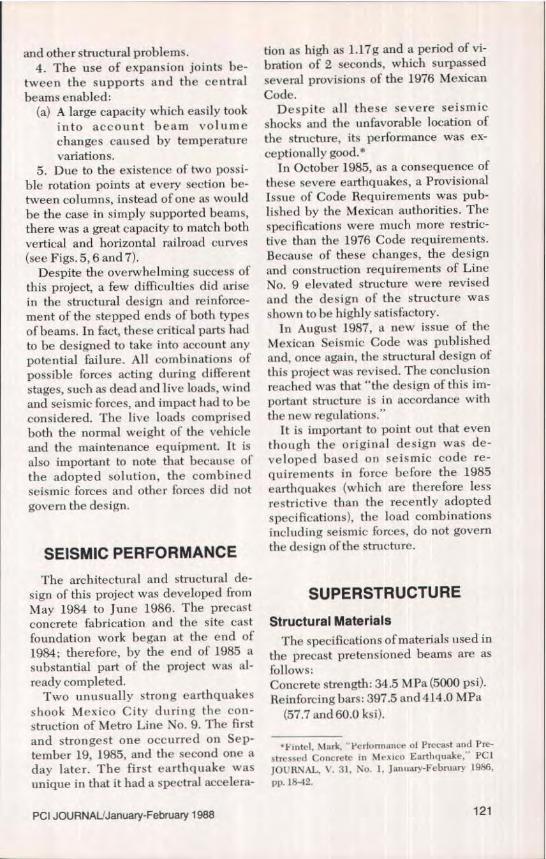
SUPERSTRUCTURE
Structural MaterialsThe specifications of materials used in
the precast pretensioned beams are asfollows:Concrete strength: 34.5 MPa (5000 psi).Reinforcing bars: 397.5 and 414.0MPa
(57,7 and 60.0 ksi).
9 Intel, Mark, ' 1 ertormance of Precast and Pre-
stressed Concrete in Mexico Earthquake," PCLJOURNAL, V. 31, No. 1, January-Februar y 1986,
pp. 18-42.
PCI JOURNAL'January-February 1988 121
N6.86
T,CC
5.58
- 3 15^ 7
4.72 .573.57t
5.58,
1.31'SEE__....^
TYPICAL CROSS SECTIONAT ENDS CROSS SECTION
+ +++ ^22j-I/2" STRANDS44-++++
ir ++++tom'+- ++++
1.31
DETAIL
G.,nr + L-,-...•a• s-'- . ,, cu bear I ' v, a I r 1 ueruer oeamsf are precast pretensloned.
LL ili80.38'
ELEVATION
Fig. 9. Overall view of Line No. 9 structure.
Prestressing steel: 1.86 MPa (270 ksi).Diameter of prestressing steel: 12.7 mm
( i/2 in.).
The specifications of materials used inthe cast-in-place diaphragms and top-pings are as follows:Concrete strength: 34.5 and 24.6 MPa
Central BeamsThese beams are 24.5 m (80.38 ft) long
and have a T cross section with smallflanges at their bottoms. They have aconstant depth of 1.70 m (5.58 ft) with anupper flange width of 2090 mm (6.86 ft).The upper flange thickness varies from80 to 120 mm (3.15 to 4.72 in.). The bot-tom flange width is 400 mm (1.31 ft),
with the thickness varying from 150 to2.50 mm (5.9 to 9.84 in.). The web thick-ness is 120 mm (4.72 in.) except at theends where it is 400 mm (1.31 ft). Thecentral beams are stepped at their endsso that they can rest on support beams.
To take into account any volumetricchanges produced by temperature vari-ations, the beam is provided with onefixed end and one sliding support at theother end (see Figs. 8 and 9).
The central beams are prestressedwith 26 straight strands, located at thebottom flange; some of them are un-bonded at their ends. The beams alsocontain 12.7 mm ( 1/2 in.) diameter verti-cal stirrups and ties.
Support BeamsThese beams are 16.46 m (54.0 ft) long
and have a T cross section, with smallflanges at their bottoms. They have aconstant depth of 2200 mm (7.22 ft) in
PCI JOURNAL'January-February 1988 123
6.86' H- 3.15"I .57„
5,58
7,22'
3.15"I.57"3.94'
7.22'
6.86'
^- 1.31'
TYPICAL CROSS SECTION
7t
t++ +++
DETAIL
I. 31'
AT COLUMNS CROSS SECTION
5 4' _
ELEVATION
Fin 1!1 a . .......••rr•.•,• •••,•.•^^^^ 1^^^^.^^^ ^.civci ueauii arc Niecasr pretensionea.
28.29'
IEI•
FROM CABLE4.49
I. STRANDS}
TO I
`POST-TENSIONED CABLESCABLE
4 STRANDS
TYPICAL CROSS SECTION ELEVATION
Fig. 11. End beam diaphragms (secondary beams) are cast-in -place post-tensloneu.
their central portion between columns;however, they are tapered at their ends,from 2200 to 1700 mm (7.22 to 5.58 ft).They have the same flange dimensionsas the central beams. The web thicknessis 200 mm (7.87 in.) except at the endswhere it is 400 mm (1.31 ft).
To provide support to the centralbeams, they are stepped at their ends(see Fig. 10).
The support beams are prestressedwith 24 straight strands, all of which arelocated at their top flange. These beamsalso have 12.7 mm (45 in.) diameter ver-tical stirrups and ties.
DiaphragmsThese seven beams which are per-
pendicular to the axis of the structureare cast in place, rectangular shaped,and they are 7.10 m (23.3 ft) long.
There are two types of diaphragms -those which are located at the columnaxis, and those which are placed at theends of both beams (central and supportbeams). There are also diaphragmswhich are placed at the middle of thecentral beams.
Column axis diaphragms are 900 min(2.95 ft) wide with a depth varying from2167 to 2152 mm (7.11 to 7.06 ft). Therest of the diaphragms are 300 mm (11.8in.) wide with a depth varying from 1369to 1503 mm (4.49 to 4.93 ft) as shown in
Figs. 11 and 12.Column diaphragms are provided
with two 8-strand upper cables and two8-strand bottom cables. The top andbottom parts of the end beam diaphragmare furnished with a 4-strand cable. Thediaphragms at the center of centralbeams are provided with a 4-strand
Fig. 12a. Underside view of diaphragms.
PCI JOURNAUJanuary- February 1988 125
I ^. Mr.
aI.4
to i
ir
I
1i1/
Fig. 12d. Support beams and main beam in place.
Fig. 12e. Connection detail of support beam and main beam.
rly. I o. tievauon ana aetails of sliding support.
11. 42" 4_
GROOVED SURFACEBASEIE_
27r' Aff+.77'
O-RIH9gAR_ VIRG+N TEFLON
286'
NEOPRENE PLATE 0.79°
1.60. 79"GAP
BOLTS
$1.r7" i^ ' T v5.58"4 II I I i 1
Y\PE TA I L . 2
GAP 7
GAP ^I.6'^
CENTRAL BEAM
ELEVATION
SUPPORT BEAM
DETAIL 2
1y. IY. ClevdLIUF, ana aeiaiis of tlxed support.
upper cable and a 12-strand bottomcable. These beams are also furnishedwith 12.7 mm ('/2 in.) diameter reinforc-ing steel.
ToppingAbove the main beams and dia-
phragms, a 24.6 MFa (3750 psi) 60 mm(2.36 in.) thick concrete topping is pro-vided. This topping is wire mesh rein-forced.
Sliding SupportEach sliding support placed at one end
of the main central beams is composedof 290x290x19mmand290x330x22mm (11.42 x 11.42 x 3/4 in. and 11.42 x13.0 x 7/s in.) embedded steel plates. An-chorage is provided with four 12.7 mm(1/2 in.) diameter bolts, which have ananchoring length of 675 mm (2.21 ft).
The main support beams are providedwith steel rings, having a 32 x 26 mm(1 1/4 x 1.02 in.) cross section, an exterior
128
ROOF TRANSVERSAL BEAM
46.57 1—DOME
ROOF CENTRAL ANDSUPPORTS BEAMS
CAST IN PLACECOLUMNS
PLATFORM
PLATFORM CENTRAL
STATION CENTRAL AND SUPPORT BEAMS
AND SUPPORT BEAMS
COLUMNS
i^ U 0 U U
Fig. 15. Typical cross section of station structure.
diameter of 292 mm (11.5 in.), and aninterior diameter of 266 mm (10.97 in.),Steel rings are welded to the steelplates. Stainless steel plates (A-304)are also provided.
Finally, to complete this support, aneoprene plate reinforced by a 1.2 mm(3.64 in.) thick fiberglass is providedalong with an O-RING of virgin tellon0.4 mm ( l/s4 in.) thick and another 20 mm(0.79 in.) thick plate as shown in Fig. 13.
Fixed SupportThese supports are similar to the
sliding ones but without fiberglass. Thesteel plates of the main central beamshave a grooved surface (see Fig. 14).
STATIONS
This line comprises four stations. The
Palacio de los Deportes station and thePuebla station are similar to each other,whereas the Velodromo station and thePantitlan station demanded special de-sign considerations.
The station structure is similar to thatof the intermediate line portions alreadydescribed. However, this particularstructure has two frames, one at the trainlevel and the other one at the roof level(see Figs. 15,16,17 and 18).
The station structures consist of adouble column system that spans 30.00,35.00 and 40.00 m (98.4, 114.8 and 131.2ft) between column centerlines.
The frames placed at train level con-sist of eight Gerber beams, four ofwhich, i.e., the ones located at the cen-tral portion, are similar to those of theintermediate line portions. The rest ofthe Gerber beams are placed laterallywith a vertical rise of 1500 mm (4.92 ft)above the plane of the previously de-
PC! JOURNALIJanuary-February 1988 129
Fig. 16. Station structure.
Fig. 17. Station's access.
130
Fig. 18. Station's interior.
scribed four beams, so as to define theplatforms of the station. Perpendicularto these eight beams there are alsoseven transverse beams, here referred toas diaphragms, which are cast in place inaddition to the topping.
Each of above described beams con-sist of central beams and support beams.The span of the central beams variesfrom 15.50 to 24.50 in (50.9 to 80.4 ft).Support beams are 16.46 m (54.0 ft) long.Dimensional characteristics of thesebeams, the diaphragms, and toppings,are similar to those of the intermediateline between stations.
The roof level frames are supportedby cast-in-place concrete columns,which act like an extension of the dou-ble columns. Roof frames consist of twoL longitudinal Gerber beams and sev-eral T beams to support the domes.
Every L beam is also composed of'central beams and support beams.
At the ends of the stations the roof
level is higher than the one in the mid-dle of them, to allow for space neededfor passenger walkway crossings.
Station Central BeamsThese beams are similar to the central
beams already described except they areonly 15.5 m or 24.5 m (50.9 ft or 80.4 ft)long and the upper flange is 1490 mm(4.89 ft) wide, with the depth varyingfrom 94 to 120 mm (3.7 to4.72 in.)
Station Support BeamsThese beams are also similar to the sup-port beams already described exceptthat the top flange is 1490 mm (4.89 ft)wide and its depth varies from 94 to 120mm (3.7 to 4.72 in.),
Platform Central BeamsThese beams are 24.5 m (80.38 ft) long
and T shaped with a small bottom
PCI JOURNAUJanuary-February 1988 131
7,22'
ITIRRU PS
-SEE DETAIL
31`
7. 22^
=dim
X05"3.94
TYPICAL CROSS SECTION
3 28^
4.17__1 0.5
1.31
AT ENDS CROSS SECTION
+ 1/2° STRANDS
+^;+ + + 5,91 and 80.38'
ELEVATION
DETAIL
rrg. 19. Platform central beams are precast pretensioned.
flange. They have a constant depth of2200 mm (7.22 ft). Its top flange is 1000mm (3.28 ft) wide, having a thicknessvarying from 106 to 120 mm (4.17 to 4.72in.)_ The bottom flange is 400 mm (1.31ft) wide and 150 mm (5.91 in.) thick. Theweb thickness is constant and equal to200 mm (7.87 in.) as shown in Fig, 19.
These beams have 14 straight strandslocated at the bottom flanges. Some ofthe strands are unbonded at the ends ofthe beams. In addition, there are stir-
nips, ties and reinforcing bars 112.7 mm( ys in.) in diameter] in the beams.
Platform Support BeamsThese beams are 16.46 m (54.00 ft)
Iong. Their dimensions and reinforce-ment are similar to the platform centralbeams (see Fig. 20).
Roof Central BeamsThese beams are 24.5 m (80.38 ft)
132
TIES
3,28' J
RIB ,
SEE DETAIL
1 7.2 2'TIRR11PS
5.91--11
3.28
7.2 2'
40
L31'
TYPICAL CROSS SECTION
X7.87
DETAIL
^ 1.3 1
AT ENDS CROSS SECTION
5 4.0 f T
ELEVATIONANDS
Fig. 20. Platform support beams are precast pretensioned.
long. They are L shaped with a depth of2000 mm (6.56 ft). The width of itsflange is 700 mm (2.30 ft) with a depthvarying from 350 to 1050 mm (1.15 to3.44 if).
The web width varies from 350 to 450mm (1.15 to 1.48 ft). At their ends theyhave a rectangular cross section. Thewidth varies from 600 to 700 mm (1.97 to2.30 ft) as shown in Fig. 21.
These beams have 26 straight strandslocated at their flanges. They also have
stirrups and other reinforcing bars [12.7mm ( r/2 in.) in diameter].
Roof Support BeamsThese beams are 16.44 m (53,94 It)
long and are also L shaped. They areprestressed with 26 straight strands,some of which are unbonded, and theyare reinforced with stirrups and bars[12.7 mm ( 1/2 in.) in diameter] as shownin Fig. 22.
PCI JOURNALJanuary-February 1988 133
DETAIL
'SEE DETAIL
80.30'+84 I 151 4_ °
2i30--4- ELEVATION
3.05
6.56'
2.38'
1.15'
1-
/2"1/2" STRAN
TYPICAL CROSS SECTION
i- g. 21. Hoot central beams are precast pretensioned.
Roof Transverse Beams
These transverse T beams are 14.19 m(46.57 ft) long. They have a depth of 700mm (2.30 ff) and the web thickness is250 mm (9.84 in.). Their flanges are 2500min (8.20 ft) and their thickness variesfrom 40 to 130 mm (1.57 to 5.11 in.).They are stepped at their ends so thatthey can be supported by the L beams.
The beams have 12 straight strandsand their stirrups are also 12.7 mm (14in.) in diameter, Their flanges are rein-Forced by a 6 x 6 - 6/6 wire mesh.
SUBSTRUCTUREThe substructure used for this project
consists of a double column system thatforms a type of frame with main supportbeams. These columns have a variabledepth, rectangular section and at theirtops they are crowned with a horizontalbeam which supports the main beams ofthe superstructure.
Due to the frame action between dou-ble columns and support beams, it waspossible to obtain smaller column sec-tions as compared with the ones used forLine No. 4, thus increasing the capacityto resist both vertical and horizontalloads (especially seismic forces).
The column cross sections vary from800 x 3100 mm (2.62 x 10.17 ft) at thebottom to 800 x 3600 mm (2,62 x 11.81 ft)(minimum dimension) at their upperside.
The horizontal beams are designed asan extension of the columns. Their pur-pose is to support main beams. Theyalso have rectangular sections 900 mm(2.95 ft) wide with a variable depth from500 to 800 m (1.64 to 2.62 ft). Thesebeams act also as diaphragms for thehorizontal Gerber frames (see Fig. 23).
These columns and transverse beamswere cast in place using a concretestrength of 34.5 MPa (5000 psi) andreinforcing bars of414 MPa (60 ksi). Thecolumn bars are 31.7 mm (P/4 in.) in di-
134
1.15'SEE OETAtL -h
Ii + 1/2 STRANDS
+ +
6.56
DETAIL
1.15
2.30 ^ 54: 00
TYPICAL CROSS SECTIONELEVATION
Fig. 22. Roof support beams are precast pretensioned.
ameter. There are 12.7 and 9.5 mm ('/sand % in.) diameter stirrups. They arealso reinforced with a vertical 6 x 6 - 8/8wire mesh. The horizontal beamsformed at their tops have 25.4 mm (1.0in.) diameter main reinforcing bars and12.7 mm ( yz in.) diameter stirrups andties.
FOUNDATIONThe foundation of this bridge is semi-
balanced and consists of cast-in-placecaissons and precast concrete frictionpiles. The caisson dimensions are 15.0 x8.0 m (49.21 x 26.25 ft) and 1.80 m (5.91ft) high. The dimensions of the stationcaissons are 20.0 x 10.0 m (65.62 x 32.81ft) and 2.20 in (7.22 ft) high.
CaissonsThese caissons are framed with lon-
gitudinal and transverse beams and two
slabs; one at their bottom and the otherone at their top side (see Fig. 23 For planand elevation details).
The beam width varies from 400 to850 mm (1.31 to 2.79 ft). The top slab is150 mm (5.91 in.) thick and the bottomslab is 300 mm (11.81 in.) thick.
The concrete strength is 24.6 MPa(3571 psi) and its reinforcing steel is 414MPa (60 ksi).
PilesEach caisson is supported on 20 fric-
tion piles, except at the station wherethey are supported by 49 piles.
Friction piles are 36.0 m (118.11 ft)long, having a square cross section 300 x300 mm (11.81 x 11.81 ft), They are di-vided into three 12 m (39.37 ft) longsections and are provided with weldedsteel plates at their ends. The concretestrength is 19.6 MPa (2845 psi) and theyield strength of the reinforcing bars is393 MPa (56 ksi).
PCI JOURNAL/January-February 1988 135
-I---. 26.58'
)SUPPORT SEAMS
A
Ui1LLi 4LI
MAIL
NPT
:±_
ELEVATION
list' 017
2,62'
CROSS SECTION A-A CROSS SECTION B8
COLUMNS
49,2 1'OLUMNS_. TOP SLAB
FRICCION BOTTOM--
P1LE5 SLAB
CAiSSON ELEVATION
7550 4921__Q__ _-_e8
L64
9.19
7.87 2625
1.64
9.19
CAISSON PLAN
i. oubsiructure and loundation (columns and caisson details).
136
EXPRESSWAY PEDESTRIAN BRIDGE PLAN
13,1216.56 1 1 6.561
3.15° - 1.57'3.94" 3.15"
1.57'
3.94
3.94 3_28 _ ^4'
TYPICAL CROSS SECTION
FROM 1320.9' TO 2521.61
SIMPLE-SUPPORTED BEAMS ELEVATION l SEE DETAIL 1)
2057' AND 2736'
L ---
GERBERSUPPORT BEAMS EL EVATIO N (SEE DETAIL 21
Uk!TRANDS + i.17ST;OS
DETAIL I DETAIL 2
Fig. 24. Expressway pedestrian bridge (from Velodromo station to bus station).
PCI JOURNALJJanuary-February 1988 137
Fig. 25. Pedestrian bridges
COMPLEMENTARYSTRUCTURES
Pantitlan Pedestrian BridgesSixteen pedestrian bridges were built
as complementary structures at the Pan-titlan terminal station. These bridgeshave spans ranging from 11.0 to 40 in(from 36.09 to 131.23 ft) and widths from1.5 to 14.2in (fromn4.92to49.59ft).Thetotal length of these bridges is 1800 m(5905.5 it). The components of thesebridges were mainly precast prestressedelements.
Expressway Pedestrian BridgeIn order to gain access from Velodromo
station of Line No. 9, which is located atthe northern side of' Miguel AlemanViaduct, to local bus stations located inthe southern side of this freeway, it wasnecessary to build a 144.9 in (475.39 ft)long pedestrian bridge to cross the
heavily traveled expressway.The structural solution of this pedes-
trian bridge consisted of four simplysupported beams that span 13.21, 19.08,21.21 and 25.22 in (43.34, 62.60, 69.59and 82.74 ft), respectively, and a Gerbersystem with three spans of 20.57, 20.61and 27.36 in (67.49, 67.62 and 89.76 ft).This Gerber system consists of one cen-tral beam, simply supported, 20,61 m(67.62 ft) long and two support beams20.57 and 27.36 in (67.49 and 89.76 ft)long.
These support beams are cantilev-ered on one side. The simply support-ed bean-► and the Gerber beams wereprecast and pretensioned in a plant lo-cated 80.0 km (50.0 miles) from the job-site. They are box sectioned with a verywide top flange (see Figs. 24,25 and 26).
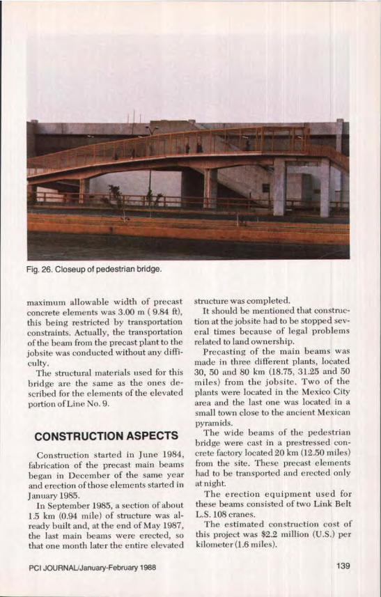
The major feature of this structure isthe wide width beams. They are 4.00 in(13.12 ft) wide and are the first elementsto be precast in Mexico City with a 4.00in (13.12 ft) width. Prior to this, the
138
Fig. 26. Closeup of pedestrian bridge.
maximum allowable width of precastconcrete elements was 3.00 m ( 9.84 ft),this being restricted by transportationconstraints. Actually, the transportationof the beam from the precast plant to thejobsite was conducted without any diffi-culty.
The structural materials used for thisbridge are the same as the ones de-scribed for the elements of the elevatedportion ofLine No. 9.
CONSTRUCTION ASPECTSConstruction started in June 1984,
fabrication of the precast main beamsbegan in December of the same yearand erection of those elements started inJanuary 1985.
In September 1985, a section of about1.5 km (0.94 mile) of structure was al-ready built and, at the end of May 1987,the last main beams were erected, sothat one month later the entire elevated
structure was completed.It should be mentioned that construc-
tion at the jobsite had to be stopped sev-eral times because of legal problemsrelated to land ownership.
Precasting of the main beams wasmade in three different plants, located30, 50 and 80 km (18.75, 31.25 and 50miles) from the jobsite. Two of theplants were located in the Mexico Cityarea and the last one was located in asmall town close to the ancient Mexicanpyramids.
The wide beams of the pedestrianbridge were cast in a prestressed con-crete factory located 20 km (12.50 miles)from the site. These precast elementshad to be transported and erected onlyat night.
The erection equipment used forthese beams consisted of two Link BeltL.S. 108 cranes.
The estimated construction cost ofthis project was $2.2 million (U.S.) perkilometer (1.6 miles).
PCI JOURNALJJanuary-February 1988 139
Fig. 27. Overall view of Line No. 9.
Fig. 28. Underside view of elevated Metro.
140
CONCLUDING REMARKSFrom the experiences gained on this
project, it has been shown that precastprestressed concrete is feasible andeconomically competitive for elevatedrapid transportation people systems(Metro) or guideway and railroad bridgesuperstructures. This despite the poorcharacteristics of the Mexico City sub-soil, the severe magnitude of seismicforces and the ever present budgetaryconstraints,
The adopted structural system can beused efficiently to account for very largehorizontal and vertical railroad curva-tures, taking advantage of the angularvariability of double column systems.
In addition, the construction tech-nique has proven to be successful usingthe 40 m (131.23 ft) prestressed beam,by reducing the depth and weight of thestructure with a high level of quality andaesthetics (see Figs. 27 and2S),
Another important feature is that theconstruction schedule was reduced byseveral months. This was made possibleby precasting the major structural ele-ments in a plant while the foundationwork and substructure could be carriedout simultaneously.
In retrospect, the results obtained bycontracting three precast prestressedplants to manufacture the structuralcomponents proved to be very satisfac-tory. Also, the mixture of precast ele-ments from three different plants fittedexceptionally well on site and did notpresent any difficulties.
This structural design system haswide possibilities of adaptation to dif-
ferent layouts. Currently, other elevatedIines are being designed. The designhas been improved and is now evenmore efficient, flexible and cost effec-tive. Unquestionably, precast and pre-stressed concrete will be used more ex-tensively in rapid transit systems notonly in Mexico but throughout theworld.
CREDITS
Owner: Departamento del Distrito Fed-eral, Secretaria General de Obras(Mexico City Authorities).
Promoter: Coinision de Vialidad yTransporte Urbano, COVITUR(Urban Transportation Commission).
Structural Architectural and Station In-stallation Designer: