James A. FitzPatrick Nuclear Power Plant 268 Lake Road P.O. Box 41 Lycoming, New York 13093 315-342-3840 A NewYorkPower S.Authorily Michael J. Colomb Site Executive Officer December 7, 1999 JAFP-99-0319 United States Nuclear Regulatory Commission Attn: Document Control Desk Mail Station P1-137 Washington, D.C. 20555 Subject: Additional Information Needed to Complete Review of FitzPatrick Proposed One-Time Only Change to Technical Specifications Regarding RHRSW Allowable Out of Service Time References: 1. JPN-99-030, September 29, 1999, Proposed One-Time-Only Change to the Technical Specifications Regarding RHRSW Allowable Out-of Service Time (JPTS-99-005) Dear Sir: The Reference 1 proposed amendment to the James A. FitzPatrick (JAF) Technical Specifications is currently under review by your staff. Attachment I is a Request for Additional Information (RAI) forwarded to our staff (via E-mail) from the technical reviewer on your staff to support his review of this proposed amendment. This RAI is answered in Attachments II, Ill, & IV of this letter as outlined below: "* Attachment II addresses questions 1, 3 and 4 of the RAI "* Attachment III addresses question 2 of the RAI "* Attachment IV is a compilation of relevant sections of the JAF Individual Plant Examination for reference in evaluating the answer to question 1 of the RAI Please note that the time period evaluated by Attachment II is 14 days. The Reference 1 proposed Technical Specification amendment requests a one-time-only extension to the RHRSW allowable out of service time to 11 days. The 14 day period evaluated in Attachment II is therefore conservative relative to the proposed amendment and risk exposure numbers can be linearly adjusted accordingly. Very truly yours, Michael J. Colom 7i MJC:MA:Ias Attachments as stated Cc: next page PaL, sYywO~Q>3 Doý ,M-
Transcript
James A. FitzPatrick Nuclear Power Plant 268 Lake Road P.O. Box 41 Lycoming, New York 13093
315-342-3840
A NewYorkPower S.Authorily
Michael J. Colomb Site Executive Officer
December 7, 1999 JAFP-99-0319
United States Nuclear Regulatory Commission Attn: Document Control Desk Mail Station P1-137 Washington, D.C. 20555
Subject: Additional Information Needed to Complete Review of FitzPatrick Proposed One-Time Only Change to Technical Specifications Regarding RHRSW Allowable Out of Service Time
References: 1. JPN-99-030, September 29, 1999, Proposed One-Time-Only Change to the Technical Specifications Regarding RHRSW Allowable Out-ofService Time (JPTS-99-005)
Dear Sir:
The Reference 1 proposed amendment to the James A. FitzPatrick (JAF) Technical Specifications is currently under review by your staff. Attachment I is a Request for Additional Information (RAI) forwarded to our staff (via E-mail) from the technical reviewer on your staff to support his review of this proposed amendment. This RAI is answered in Attachments II, Ill, & IV of this letter as outlined below:
"* Attachment II addresses questions 1, 3 and 4 of the RAI
"* Attachment III addresses question 2 of the RAI
"* Attachment IV is a compilation of relevant sections of the JAF Individual Plant Examination for reference in evaluating the answer to question 1 of the RAI
Please note that the time period evaluated by Attachment II is 14 days. The Reference 1 proposed Technical Specification amendment requests a one-time-only extension to the RHRSW allowable out of service time to 11 days. The 14 day period evaluated in Attachment II is therefore conservative relative to the proposed amendment and risk exposure numbers can be linearly adjusted accordingly.
Very truly yours,
Michael J. Colom 7i
MJC:MA:Ias Attachments as stated Cc: next page
PaL, sYywO~Q>3
Doý,M-
cc: Regional Administrator U. S. Nuclear Regulatory Commission 475 Allendale Road King of Prussia, PA 19406
Office of the Resident Inspector U. S. Nuclear Regulatory Commission P.O. Box 136 Lycoming, NY 13093
Mr. G. Vissing, Project Manager Project Directorate I Division of Licensing Project Management U. S. Nuclear Regulatory Commission Mail Stop OWFN 8C2 Washington, DC 20555
Mr. F. William Valentino, President New York State Energy Research and Development Authority Corporate Plaza West 296 Washington Avenue Extension Albany, NY 12203-6399
Attachment I
ONE-TIME-ONLY CHANGE TO THE TECHNICAL SPECIFICATIONS REGARDING RHRSW ALLOWABLE OUT-OF-SERVICE TIME
(JPTS-99-005)
Copy of NRC Request for Additional Information
New York Power Authority
JAMES A. FITZPATRICK NUCLEAR POWER PLANT Docket No. 50-333
DPR-59
11/01/99 Additional Information Needed to Complete Review of
Fitzpatrick Proposed One-Time Only Change to TS Regarding RHRSW Allowable Out-of-Service Time
1. To ensure that the specific PRA is adequate to support the requested TS change, please furnish the following information on PRA quality: - verification the PRA reflects the as-built, as-operated plant - a description of updates of the PRA since the last review cycle, including
corrections of weaknesses identified by past reviews - details of the peer review process, a summary of the peer review findings, and a
discussion of the independence of internal reviews/reviewers - a description of PRA quality assurance methods - results of reviews of pertinent accident sequences and cutsets for modelling
adequacy and completeness with respect to this application
2. Please describe the constraints that the CRMP would place on maintenance activities and the surveillances that will be required when RHRSW "A" is out of service, particularly with regard to safeguards bus 10600, battery control board 71BCB-2B, the remaining train of RHR service water, and the fire protection system. In determining whether other maintenance activities would be permitted concurrent with the RHRSW outage, what is the maximum CDF and LERF that would be permitted by the CRMP during the outage?
3. The extended outage would affect/increase the frequency of TW sequences, which typically involve containment failure prior to core damage. As such, the ALERF and CLERP associated with the request would appear to be close to the ACDF and CCDP for the request. Please describe the challenge to containment and the expected containment performance in sequences that are introduced/increased as a result of the request. Provide an estimate of the LERF and CLERP for the outage.
4. Loss of safeguards bus 10600 appears to lead directly to containment failure/leakage and subsequent core damage. Describe in more detail the consequential failures that occur as a result of losing bus 10600. Explain how the loss of the bus leads to containment rupture or leakage. Explain why operator failure to crosstie RHRSW with the fire protection system does not appear in any of the cutsets listed in Table 2 of JAF-ANAL-RHR-03422.
Attachment II
ONE-TIME-ONLY CHANGE TO THE TECHNICAL SPECIFICATIONS REGARDING RHRSW ALLOWABLE OUT-OF-SERVICE TIME
(JPTS-99-005)
Answers to NRC RAI Questions 1, 3 and 4
New York Power Authority
JAMES A. FITZPATRICK NUCLEAR POWER PLANT Docket No. 50-333
DPR-59
123 Main Street White Plains, New York 10601 914 681.6200
SNewYorkPower 4 Authority
November 8, 1999 RET-99-632
TO: M. Abramski
FROM : J.A. Circle
SUBJECT: JAF - Response to NRC Reviewer Questions on RHRSW Loop A Proposed Outaae
As per your request made on November 3, 1999, Reactor Engineering-NSA has responded to the three assigned requests made by Bob Palla of the NRC regarding possibly extending the LCO AOT to 14 days for replacement of RHRSW strainer 10S5A. As noted in the October 28, 1999 conference call, the analyses performed for the at power RHRSW loop A outage configuration was conservative and not risk significant. The response to assigned questions 1, 3, and 4 is attached.
Please note that the use of information for any other purpose other than the subiect matter of this memo is not recommended. This material is not a substitute for deterministic analysis of issues dealing with design basis accidents, Final Safety Analysis Report, and technical specifications requirements.
If you have any questions, please feel free to contact me at WPO extension 6562.
Approved by:
C.N. Yeh
Reviewed by:
7'J.A. F�vara
cc: H. Salmon; T. Dougherty; G. Grochowski; G. Tasick (JAF); T. Herrmann (JAF); NSA Group; NSA File 8.13
Excellence - Innovation - Integrity - Teamwork
Memorandum
CAý1ý
Additional Information Needed to Complete Review of Fitzpatrick Proposed One-Time Only Change to TS Regarding
RHRSW Allowable Out-of-Service Time
Request 1. To ensure that the specific PRA is adequate to support the requested TS change,
please furnish the following information on PRA quality: verification the PRA reflects the as-built, as-operated plant a description of updates of the PRA since the last review cycle, including corrections of weaknesses identified by past reviews details of the peer review process, a summary of the peer review findings, and a discussion of the independence of internal reviews/reviewers a description of PRA quality assurance methods results of reviews of pertinent accident sequences and cutsets for modeling adequacy and completeness with respect to this application.
Response
Please refer to the JAF IPE update1 sections 1.5 and 1.6 and chapters 5 and 6. They contain detailed information on the state of the data prior to the update, the reasons for the update, verification of the IPE, a comparison of results and data, and specific results of the peer review and BWROG certification process. The JAF IPE update was prepared in conformance with NYPA procedures such as DCM-12 2. The specific analysis for assessing the work during the initially proposed NMCA outage, JAF-ANALRHR-03422 3 was also performed and approved in conformance to DCM-12.
Request
3. The extended outage would affect/increase the frequency of TW sequences, which typically involve containment failure prior to core damage. As such, the LiLERF and CLERP associated with the request would appear to be close to the LICDF and CCDP for the request. Please describe the challenge to containment and the expected containment performance in sequences that are introduced/increased as a result of the request. Provide an estimate of the LERF and CLERP for the outage.
Response
The two dominant TW sequences, which together contribute 2.38 x 10⁶ per year to,
1 JAF-RPT-MULTI-02107, Rev. 1, "JAF Individual Plant Examination", April 1998 2 JAF Design Control Manual, "Review and Approval of NYPA Generated Documents", DCM-12A, Rev. 3,
April 1999. 3 JAF-ANAL-RHR-03422, Rev. 0, "Probabilistic Evaluation in Support of Technical Specification
Amendment to Extend RHR Service Water Loop A Outaqe", September 1999.
core damage and LERF for this configuration, are described as follows:
TDC-B-4-7(TDC-B*/B 1 *lIU *Wl *W2*Y-LOCAL*FLAG-RUP* U I -R* U3-R'V1 -R)
This sequence has a contribution of 1.19 x 10⁶ per year. It is initiated by a loss of 125V dc battery control board 71BCB-2B (division II), offsite power to one division only and HPCI are available. However, due to unavailability of loop A of RHRSW, suppression pool cooling and containment spray fail (WI *W2) resulting in high suppression pool pressure. Failure of division II dc results in failure of 4.16kV bus 10600 with subsequent failure of 120V ac division II ac distribution panel 71AC-B2, and containment vent valve 27AOV-1 17 to open via the relay room. Provisions for manually opening valves locally exist via EOP support procedure EP-6, however, in this sequence, operator fail to do so (Y-LOCAL). Containment overpressure eventually results in rupture (FLAG-RUP) with HPCI (UI-R), CRD (U3-R), and Condensate (VI-R) all failing post-rupture resulting in core damage.
This sequence has a contribution of 1.19 x 10⁶ per year. The scenario is similar to TDC-B-4-7 above except that it is initiated by a loss of 4.16kV bus 10600.
In the base IPE submittal, the large early release frequency (LERF) was estimated to be 6.62 x 10.7 per year and is dominated by SBO sequences. The contribution of TW sequences to LERF is 6.97 x 10⁸ per year which is 10.5% of the total frequency. For CDF, TW sequences contribute 2.72 x 10.7 per year, or approximately 12 percent to the total point-estimate CDF. A quantification of TW sequences leading to core damage was performed with an unavailable loop A of RHRSW and with retained maintenance unavailability terms. The resultant CDF is 3.83 x 10⁶ per year, or a 13.09 time increase over the base TW contribution to CDF. Applying this factor to the LERF TW contribution results in a TW contribution to LERF due to an unavailable loop A of RHRSW of 9.13 x 10 7 per year, or an increase of 8.43 x 10.7 per year over the base case. For a maximum planned 14-day AOT, the conditional large early release
probability (CLERP) is estimated to be 14 days 07 365 ays/earx 8.43 x 10 per year, or 3.23 x 365 days/year
108. This falls below the EPRI PSA Applications Guide 4 threshold of 10-7 for risk significance in a change in LERP.
Request
4 EPRI TR-1 05396, PSA Applications Guide, August 1995.
4. Loss of safeguards bus 10600 appears to lead directly to containment failure/leakage and subsequent core damage. Describe in more detail the consequential failures that occur as a result of losing bus 10600. Explain how the loss of the bus leads to containment rupture or leakage. Explain why operator failure to crosstie RHRSW with the fire protection system does not appear in any of the cutsets listed in Table 2 of JAF-ANAL-RHR-03422.
Response
Failure of 4.16kV bus 10600 while RHRSW loop A is unavailable will result in RHRSW loop B pumps 1 OP-1 B and 1OP-1 D to trip, which would lead to a loss of suppression pool cooling, if unmitigated by use of the fire water cross-tie. Under these conditions, core cooling and make-up can be accomplished via RCIC, CRD, SLC or the Condensate systems. However, the resulting increase in suppression pool temperature and pressure would eventually require the need to vent. If containment venting were unsuccessful, either the containment will fail by leakage or catastrophically by rupture. After failure, if core cooling cannot be re-established, core damage would ensue. A detailed description of TW sequences initiated by a loss of 4.16kV bus 10600 is contained in the IPE, section 3.1.4.8 (pp. 3-143 through 3-152).
For brevity, Table 2 of JAF-ANAL-RHR-03422 presented the first fifty minimal cut sets. The earliest appearance of one of the fire protection system recovery actions, NR-FPSRHRSW-MV, "Failure To Align Fire Protection System For Vessel Injection" (probability of non-recovery of 2.1 x 10³) is in cut set 53. An automated process using a rule file credits recoveries - a description of the rules used appears in the IPE submittal, Appendix M. Due to the large amount of cut set permutations, firewater recovery was conservatively credited only for the most likely (predominant) scenarios in the base IPE configuration. This scenario is when operators fail to open containment vent valves locally using EOP support procedure EP-6. However, crediting this recovery for local vent valves operation is conservative; it is recognized that fire water recoveries (either via cross-tie into loop A to inject RHRSW, or by direct vessel injection) can be credited for other conditions such as the random failures of the containment vent valves themselves. The addition of the non-recovery probabilities of the fire water cross-tie (either to supplant RHRSW or for direct vessel injection) will lower the already low CCDP and risk significance further.
Attachment III
ONE-TIME-ONLY CHANGE TO THE TECHNICAL SPECIFICATIONS REGARDING RHRSW ALLOWABLE OUT-OF-SERVICE TIME
(JPTS-99-005)
Answers to NRC RAI Questions 2
New York Power Authority
JAMES A. FITZPATRICK NUCLEAR POWER PLANT Docket No. 50-333
DPR-59
PURPOSE Assessment of week 02 "A" RHR/RHRSW LCO
GENERAL DESCRIPTION
The " RHR/RHRSW systems will be removed from service to perform preventive and corrective maintenance and to perform modification JD99-095, strainer improvement.
SAFETY ASSESSMENT
The assessment IAW AP 10.02 (JAF's CRMP) is MODERATE ORANGE, Significantly degraded. Marginal risk with a contingency plan to increase defense in depth.
Safety functions affected:
Containment Heat Removal Low Pressure Injection RPV Pressure Control (SDC)
Initiators of increased importance during this LCO are a loss of 10600 Bus or a loss of "B" DC power systems.
Loss of 10600 bus
An assessment of the workweek will be conducted for any impact on the ability to execute AOP-19 LOSS OF 10600 BUS. It will ensure full capability is maintained to implement AOP 19 during the LCO.
Loss of "B" DC power systems.
An assessment of the workweek will be conducted for any impact on the ability to execute AOP-46 LOSS OF DC POWER SYSTEM B. It will ensure full capability is maintained to implement AOP-46 during the LCO.
An assessment of the workweek will also ensure that:
"* Planned activities that have a potential to result in a plant transient, RPS, PCIS trip, ECCS actuation or failure are assessed for compatibility with the planned LCO.
"* NO planned degradation, through testing or maintenance, of any other Safety function is scheduled or permitted.
"* NO planned degradation of the Electric Power distribution Safety
Function is scheduled or permitted.
RESTORATION ACTION
The Shift manager should direct the LCO coordinator to initiate emergency restoration of the "A" RHR/RHRSW systems.
"* All in-progress work would be stopped and no new work commenced. Job supervisors will provide direction to workers for expeditious restoration of components.
"* A contingency work package and temporary modification will be available to install a plug in the RHRSW strainer such that firewater can be supplied to the RHR heat exchanger.
Attachment IV
ONE-TIME-ONLY CHANGE TO THE TECHNICAL SPECIFICATIONS REGARDING RHRSW ALLOWABLE OUT-OF-SERVICE TIME
(JPTS-99-005)
Compilation of Relevant Sections of JAF Individual Plant Examination for Reference in Evaluating the Answer to Question 1 of the RAI
New York Power Authority
JAMES A. FITZPATRICK NUCLEAR POWER PLANT Docket No. 50-333
DPR-59
1.4 OVERALL METHODOLOGY
The methodology adopted by the New York Power Authority satisfies the requirements of the NRC for performing an IPE. It comprised a Level I PRA and a containment performance analysis. A state-of-the-art approach using event-trees and linked fault-trees was adopted.
Event trees depict the accident sequences that follow the occurrence of an initiating event. The subsequent responses of systems determine the final status of the core and containment--the delineation of each sequence terminates with a determination of whether the core is safe, or damaged. Fault tree models were developedfor the systems depicted in the event trees and for their support systems. Both dependent and subtle failures were addressed in the study. A plantspecific failure database, human-error database, and common-cause-failure database were created to quantify the event sequences that lead to core damage.
After quantification, dominant accident sequences were reviewed to ensure their validity and to ascertain if recovery actions are feasible. System design documentation, emergency and abnormal operating procedures, emergency support procedures and testing and maintenance practices were reviewed to identify the viable recovery actions. Should recovery be feasible, the dominant accident sequences were requantified to account for it.
The containment performance analysis entailed the identification of plant damage states that characterize the reactor, containment, and core-cooling systems at the start of core damage, the modeling of the thermal-hydraulic behavior of the reactor and containment and in- and ex-vessel fission product behavior for each of the plant damage states, the characterization of containment failure modes, the selection of a containment event tree and its quantification for each plant damage state, and the characterization of radionuclide releases using a comparative approach.
1.5 CHANGES MADE IN THIS UPDATE
Significant changes have been made to the PRA model since completion of the original IPE. These changes were made to reflect both new data and calculations and modifications to the plant design and procedures.
1.5.1 Changes to Calculations and Databases
This updated IPE made use of:
* An updated initiating event database, including all scrams that occurred between 7/28/1975 and 12/31/1997.
Rev. 1 1-5
" An updated component failure and unavailability database that reflects failures that occurred between 1/1/1986 and 4/30/1995, more equipment groups in which common-cause failures may occur and current on-line maintenance practices.
"* A revised internal flooding analysis.
1.5.2 Changes to PRA Models and Data to Reflect Design and Procedure Modifications
In this update, changes were made to the PRA models to reflect design and procedure modifications made subsequent to preparation of the initial IPE. These modifications include:
" A modification to the fire protection system to allow it to supply EDG jacket cooling water directly through the ESW system cross-tie. This modification reduces the contribution to plant risk made by the dominant station blackout event. A step to direct the operator to use this cross-tie has been incorporated in procedures AOP-49 (Station Blackout) and OP-22 (Diesel Generator Emergency Power).
"* Installation of bonnet vents on the LPCI and core spray injection valves to preclude commoncause pressure locking of the valves.
" An Appendix R modification-the installation of a new keylock bypass switch that allows LPCI and core spray injection valves to be manually opened from the control room. The switch can be used to help recover from reactor pressure permissive logic failures that cause all low-pressure system injection valves to remain closed. The use of this switch would reduce the probability of core damage during LOCAs and transients with stuck open SRVs in which all low-pressure ECCSs are unavailable.
" Installation of a new keylock bypass switch to allow HPCI auto-transfer on high suppression pool level to be bypassed from the control room rather than by removing leads in a relay room panel. This action is important in ATWS events with MSIVs closed and in handling other transients and LOCAs. Steps directing the operator to use this switch in accident sequences identified in the original IPE have been incorporated in procedure EP-2 (Isolation/Interlock Overrides).
" Changes of the RHR minimum flow bypass valve positions from normally closed to normally open. This modification reduces the probability of pump damage as a result of loss of one emergency bus.
"* Installation of switches to permit transfer to the alternative power supply for LPCI injection valves to be made from the control room.
Rev. 1 1-6
" A modification to change the RCIC enclosure fan power supply from an ac feed to an ac inverter feed from a dc power source. This modification enhances the availability of the RCIC enclosure ventilation system during station blackout events
"* Revisions to OP- 19 (RCIC system), increased RCIC turbine exhaust trip set points
"* Revisions to OP-25 (CRD system) that direct operators to enhance the CRD flow in certain accident sequences.
" A new procedure EP- 10 (Fire Water Cross-tie to RHRSW Loop A When Directed by EOP-4) that directs operators to align the fire protection system to the tube side of the RHR heat exchanger in loss of containment heat removal accident sequences.
"* Revisions to AOP-49 (Station Blackout) that explicitly address bus recovery should safeguard bus tie breaker lockout relays inadvertently reset.
* Revisions to EP-6 (Post Accident Venting of Primary Containment) that direct operators to locally open valves 27AOV- 117 and 27AOV- 118 should it not be possible to open these valves from the relay room during loss of containment heat removal sequences.
Changes were also made to data to reflect revised technical specifications and changes in the ATTS instrumentation surveillance frequency from monthly to quarterly tests.
1.6 MAJOR FINDINGS
The conclusions, major findings and insights of this study are presented here and compared to the findings of the original IPE [76].
1.6.1 Conclusions
1.6.1.1 Core Damage
The total mean core damage frequency (CDF) at JAF that results from internal causes is approximately 2.44 x 10"6/ry. This frequency is significantly less than the core melt frequency safety goal of 1 x 10⁻⁴/ry.
Among the most important results of the analysis are the calculations of importance measures. The risk-reduction worth (RRW) or Fussel-Vesely importance measures rank the basic events by the reduction in CDF that would occur if that event probability were set to zero--they identify components in which improved reliability could significantly diminish
Rev. 1 1-7
the risk. The most significant risk-reduction events for the JAF internal core damage frequency are:
"* Failure to manually depressurize reactor vessel during transient (ADS-XHE-FO-X1T2).
"* Loss of power conversion system initiator (IE-T2).
"• Loss of offsite power initiator (IE-TI).
"* Loss of 125V dc battery control board 71BCB-2A initiator (IE-TDC-A).
"* RCIC pump fails to start upon demand (RCI-TDP-FS-RCIPM).
The complement to risk reduction worth is risk achievement worth (RAW). This importance measure ranks a basic event by its increase in CDF if the event's probability is set to 1. The most significant risk increase events for the JAF internal core damage frequency are:
"* RPV rupture (RPV-RUP).
"* Loss of 125V dc battery control boards 71BCB-2A and 71BCB-2B (IE-TDC-AB).
"* Common-cause failure of the station batteries (DC 1-CCF-HW-BATTS).
"* Reactor protection system failure (C).
"* Failure to manually depressurize the reactor vessel during transient (ADS-XHE-FO-X1T2).
The failure to manually depressurize the reactor during transient-initiated accident sequences appears high in both risk measures. Clearly, this event would be focused on in any attempt to further diminish risk.
The results of this study show that nine types of accidents dominate the internal core damage frequency. These accident types are transients, the loss of a division of dc power, station blackout, transients with loss of containment heat removal, anticipated transients without scram (ATWS), the loss of a 4.16kV ac safeguard bus, loss of both divisions of dc, relay room flooding and loss-of-coolant accidents (LOCAs). Their point estimates frequencies and contribution to the total internal core damage frequency are shown in Figure 1.6.1.1 and Table 1.6.1.1.
Rev. 1 1-8
Figure 1.6.1.1 Total Internal Event Core Damage Frequency
Station Blackout 15%
-- -K-ý
Transients 30%
LOCA <1%
ATWS 12%
Loss of a dc division 22%
Internal Flooding 1%
Loss of an ac division 4%
Loss of containment heat removal
Loss of both dc divisions 12% 3%
Rev. I 1-9
!
"W1-
Table 1.6.1.1
Accident Types and Their Contribution to Internal Core Damage Frequencies
Point Estimate Core Damage Frequency (/ry)
Transients with loss of all ECCS injection
Loss of a division of dc power
Station blackout
Transients with loss of containment heat removal (loss of 4.16kV ac safety bus)
ATWS
Loss of a 4.16kV ac safeguard bus
Loss of both dc divisions
Relay room flooding
LOCAs
6.56 x 10⁻⁷
% Contribution to Point Estimate Core Damage
Frequency 30
4.93 x 10⁻⁷
3.33 x 10⁻⁷
2.72 x 10⁻⁷
22
15
12
2.59 x 10⁻⁷ 12
9.23 x 10⁴
7.36 x 10⁻⁸
2.50 x 10⁻⁸
4
3
I
1.68 x 10s <1
1-10
Accident Type
Rev. I
Transients. The most important contributors to the core damage frequency initiated by internal events are transients. These sequences contribute approximately 30 percent of the total internal core damage frequency. The most dominant sequence is initiated by a complete loss of the power conversion system and subsequent random failures of HPCI and RCIC followed by the failure to depressurize to allow low-pressure coolant injection.
Loss of a division of dc power. Accident sequences with the second highest frequency are transients initiated by a loss of a division of 125V dc. These sequences contribute approximately 22 percent to total internal core damage frequency. The dominant sequences are accompanied by the loss of all high pressure injection systems requiring emergency reactor vessel depressurization, or by two stuck open relief valves. Low-pressure injection systems subsequently fail resulting in core damage.
Station blackout. Accident sequences with the third highest frequency are station blackout sequences initiated by a loss of offsite power. Station blackout accidents contribute approximately 15 percent of total internal core damage frequency. The station blackout sequence with the highest frequency is a long-term station blackout sequence where coolant injection is lost upon battery depletion.
Loss of containment heat removal. Transients with loss of containment heat removal that result in core damage are the fourth most important contributors to the internal core damage frequency. These events contribute approximately 12 percent to the total internal core damage frequency. Loss of containment heat removal will ultimately result in elevated containment pressures that will challenge containment and core integrity. Upon containment failure, core damage may then result if core-cooling systems fail to operate because of the inability of the SRVs to depressurize the reactor or because the integrity of core-cooling systems is compromised by the harsh environment created inside the reactor building following containment failure. The containment failure mode (leak or rupture) and the equipment's location determine whether equipment survives containment failure.
ATWS. ATWS sequences are the fifth most important contributors to the internal core damage frequency. ATWS sequences contribute approximately 12 percent of the total internal core damage frequency. The most dominant contributors are initiated either by a transient with the power conversion system available or a transient with the power conversion system unavailable. Core damage follows a failure of the reactor to scram and the failure of the operators to initiate SLC or boron injection using the CRD.
Loss of a division of 4.16kV ac safeguard bus. Sequences initiated by a loss of a division of 4.16kV ac are the sixth most important contributors to the internal core damage frequency. These sequences contribute approximately 4 percent to the total internal core damage frequency. The most dominant sequences are accompanied by failure of high pressure injection systems and SRVs to depressurize the reactor.
Rev. 1 1-11
Loss of both 125V dc divisions. Loss of both 125V dc divisions is the seventh most important contributor to core damage. Failure of both battery control boards result in station blackout with loss of high and low pressure injection systems and subsequent core damage. This sequence contributes approximately 3 percent to the total internal core damage frequency.
Internal flooding. An accident sequence initiated by internal flooding in the relay room contributes approximately 1 percent of the total internal core damage frequency. In this sequence, flooding causes the MSIVs to close due to relay damage in multiple panels, thus affecting other safety functions.
LOCAs. The final type of accident sequences that contribute to core damage are LOCAs. These sequences contribute less than 1 percent of the total core damage frequency. The most dominant LOCA is a catastrophic rupture of the reactor pressure vessel.
Loss of containment heat removal sequences which result in containment failure are dominated by sequences initiated by the loss of a 4.16kV ac safety bus or of a dc bus that in turn results in the failure of a 4.16kV ac bus. The subsequent failure of suppression pool cooling and failure to operate the RHR system in the torus/drywell spray mode and the failure of long-term containment venting by manual action results in containment failure by leaking (in which core damage occurs after CRD vessel injection fails) or by rupture (in which case core damage occurs after CRD injection fails and the ADS fail). The importance of the loss of a safety bus is due to the unique RHR and RHR service water (RHRSW) power supply configuration at JAF--loss of a safety bus results in the functional loss of 3 of the 4 RHR pumps. Therefore, only a single random failure or maintenance on the opposite division that eliminates the remaining pump train from service is then required for complete loss of containment heat removal capability to occur. Furthermore, the extended loss of the 4.16kV ac safety bus will result in depletion of a battery train and will cause main steam isolation valve (MSIV) closure. The condenser is then rendered unavailable for heat removal. Their contribution to the total loss of containment heat removal frequency is 2.40 x 10⁷/ry and also shown in Figure 1.6.1.2.
Rev. 1 1-12
Figure 1.6.1.2 Total Loss of Containment Heat Removal Frequency
Loss of a 4.16kV bus 99%
LOCA <1% Loss of offsite power
/ • <1%
Transients Loss of a dc division <1% <1%
Rev. I 1-13
1.6.1.2 Plant Damage States
Plant damage states define the status of the reactor, containment, and core-cooling systems at the time of core damage. Eleven plant damage states were required to adequately characterize the release of fission products. These states involve a variety of LOCA, transient and SBO events. The mean frequencies of the plant damage states and their relative contribution to the total frequency of core damage resulting from internal events (the total internal core damage frequency) are shown in Table 1.6.1.2 together with brief descriptions of the PDSs.
Plant damage state 1 is associated with 0.58 percent of the total internal core damage frequency. This plant damage state results from a short-term large loss-of-coolant accident (LOCA). HPCI and RCIC are lost on low reactor steam pressure. Subsequently the low pressure emergency core cooling systems are unavailable because of reactor pressure permissive logic faults that prevent all low pressure ECCS injection valves from opening. The ensuing boiloff of primary coolant and core damage occurs at a low reactor vessel pressure.
Plant damage state 2 is associated with 7.6 percent of the total internal core damage frequency. This plant damage state is similar to plant damage state 1, except that in plant damage state 2, an intermediate LOCA occurs.
Plant damage state 3 is associated with 50.0 percent of the total internal core damage frequency. This plant damage state results from a plant transients (non-LOCA) event. There are no stuckopen SRVs. HPCI and RCIC both fail from random mechanical faults. Subsequently, reactor depressurization fails, precluding adequate core cooling from all low-pressure reactor make-up systems. The ensuring primary coolant boil-off leads to core damage at high reactor pressure.
Plant damage state 4 is associated with 8.6 percent of the total internal core damage frequency. This plant damage state results from a long-term station blackout. While HPCI or RCIC initially work, as ac power is not recovered, the station batteries deplete, resulting in HPCI and RCIC injection failure, reclosure of the SRVs/ADS valves, and repressurization of the reactor vessel. The ensuing boiloff of primary coolant and core damage occurs at a high reactor vessel pressure-at the SRV setpoint pressure.
Plant damage state 5 is associated with 1.8 percent of the total internal core damage frequency. This plant damage state results from a short-term station blackout with early dc power failure that results in the immediate inability of HPCI or RCIC to provide high pressure coolant injection into the reactor vessel and of the SRVs/ADS valves to depressurize the reactor vessel. Core damage occurs in less than 4 hours at a high reactor vessel pressure.
Plant damage state 6 is associated with 3.5 percent of the total internal core damage frequency. This plant damage state is similar to plant damage state 4, except that in plant damage state 6, one SRV is stuck open. As a result, the boiloff of primary coolant and core damage occurs at a
Rev. 1 1-14
Table 1.6.1.2 Internal Events Plant Damage State Frequencies
Plant Damage
State Plant Damage State Vector
PDS- I A-B I -DC I -nP-RX3-I3-E3-R3-Y2-CT1-ST
Point Estimate
PDS freq./rySimplified Description
Short-term large LOCA with loss of core cooling. Core damage results at low reactor pressure. Late injection and containment heat removal is available.
1.28 x 10'
% of Total Core
Damage Frequency
0.58
PDS-2 SI-BI-DCI-nP-RX3-13-E3-R3-Y2-CTI-ST
PDS-3 T-B I-DCI -nP-RX2-13-E3-R3-Y2-CT1-ST
PDS-4 TB-B2-DC2-nP-RXI-II-EI-RI-Y2-CTI-LT
PDS-5 TB-B2-DC2-nP-RX 1-I I-El-RI -Y2-CTI-ST
PDS-6 TB-B2-DCI-P-RX3-II-El-RI-Y2-CTI-LT
Short-term medium size LOCA with loss of core cooling. Core damage results at reactor pressure. Late injection, and containment heat removal are available.
Short-term transient with loss of core cooling. Core damage results at high reactor pressure. Late injection, and containment heat removal are available.
Long-term SBO with battery depletion. Core damage results at high reactor pressure. All accident-mitigating functions are recoverable when ac power is restored.
Short-term SBO with no dc power. Core damage results high reactor pressure. All accident-mitigating functions are recoverable when ac power is restored.
Long-term SBO involving a loss of high -pressure injection because of one stuck-open safety relief valve. Core damage results at low reactor pressure. All
accident-mitigating functions are recoverable when ac power is restored.
Rev. I
1.69 x 10.
7.56 x 10.7
1.86 x 10-'
2.90 x 10.8
7.08 x 10s
7.62
49.90
8.56
1.84
3.47
1-15
Table 1.6.1.2 Internal Events Plant Damage State Frequencies
Plant Point % of Total Damage Estimate Core
State Plant Damage State Vector Simplified Description PDS Damage freq./ry Frequency
PDS-7 TB-B2-DCI-P-RX3-II-EI-RI-Y2-CTI-ST Short-term SBO involving a loss of high-pressure 5.68 x 10⁻⁹ 0.26 injection because of two stuck-open safety relief valve. Core damage results at low reactor pressure. All accident mitigating functions are recoverable when ac power is restored
PDS-8 T-BI-DCI-P-RX3-13-E3-R3-Y2-CTI-ST Short-term transient with loss of core cooling. Core 3.56 x 10.8 1.60 damage results at low reactor pressure. Late injection, and containment heat removal are available.
PDS-9 TC-BI-DCI-P-RX2-I3-E3-R3-Y2-CTI-ST Short-term ATWS with one stuck-open safety relief 1.44 x 10'8 0.65 valve that leads to early core damage at low reactor pressure following loss of reactivity control. Late injection and containment heat removal is available.
PDS-10 TC-BI-DCI-nP-RX2-I3-E3-R3-Y2-CTI-ST Short-term ATWS that leads to early core damage at 2.50 x 10' 11.25 high reactor pressure following loss of reactivity control. Late injection and containment heat removal is available.
PDS- I1 TW-BI-DC l-nP-RX2-I3-E3-R2-Y2-CT2/CT3 Transient with a loss of long-term decay heat 2.67 x 10-' 12.05 removal. Core damage results at high reactor pressure. Late in-vessel and ex-vessel injection is available.
Rev. 1 1-16
low reactor vessel pressure--a pressure below the setpoint of the SRVs.
Plant damage state 7 is associated with 0.26 percent of the total internal core damage frequency. This plant damage state results from a short-term station blackout with one stuck-open SRV in which dc power is available. Therefore, while HPCI or RCIC can operate initially, they both fail as a result of low reactor steam pressure. Early core damage occurs at low reactor vessel pressure.
Plant damage state 8 is associated with 1.60 percent of the total internal core damage frequency. This plant damage state results from a loss of offsite power and the subsequent sticking open of a single SRV. While HPCI and RCIC work initially, they fail on low reactor steam pressure, and all other coolant injection systems capable of preventing core damage are unavailable because of reactor pressure permissive logic faults that prevent all low pressure ECCS injection valves from opening. The boiloff of primary coolant and core damage occurs at a low reactor vessel pressure.
Plant damage state 9 is associated with 0.65 percent of the total internal core damage frequency. This plant damage state results from a short-term ATWS event. Initially, reactor subcriticality is achieved by tripping the recirculation pumps and inhibiting the ADS function. The SRVs open to reduce reactor pressure, but two or more SRVs fail to reclose. Subsequently, boron injection fails and core damage ensues at high reactor pressure.
Plant damage state 10 is associated with 11.25 percent of the total internal core damage frequency. This plant damage state is similar to plant damage state 9, except that in plant damage state 10, no SRV is stuck open.
Plant damage state 11 is associated with 12.05 percent of the total internal core damage frequency. This plant damage state results from transients with loss of long-term containment decay heat removal. Loss of containment heat removal results in elevated containment pressures that challenge containment integrity. Core damage results at high reactor pressure because of the inability of the SRVs to depressurize the reactor or because the harsh environment inside the reactor building compromises the integrity of core-cooling systems.
1.6.1.3 Accident Progression Analysis
A containment event tree was developed to model the progression of accidents from incipient core damage to containment failure. Each accident progression sequence was then assigned to an accident progression category (or bin) defined by the top events of the containment event tree and source terms were estimated for every outcome. The source terms were characterized according to the timing (early/late) and magnitude (low/medium-low/medium-highlhigh) of the release. Several important insights were derived from the accident progression analysis:
& No unique containment failure mechanisms were identified or extremely high containment
Rev. 1 1-17
failure frequencies found.
" Early containment failure is more probable than late containment failure. The conditional probabilities and frequencies of containment failure resulting from internal events are shown in Figure 1.6.1.3.
"* The conditional probability of containment failure is high for all plant damage states.
"* In long-term station blackout plant damage states, the conditional probability of early containment failure caused by drywell liner melt-through is high.
"* The probability of arresting core damage once coolant injection to the reactor vessel is restored is low for all plant damage states.
"* Early or late wetwell failure is unlikely because, if wetwell venting can be established before vessel breach, wetwell failure is precluded.
"* Drywell failure is the most probable mode of containment failure.
"* The high probabilities associated with the cooling of core debris can be attributed to the high probability of maintaining coolant injection or drywell sprays operation.
" Drywell sprays are an effective means of providing water to the top of the core debris after the debris is released from the reactor vessel, cooling the debris, and making core-concrete interaction less likely. In the absence of drywell sprays, core-concrete interactions are likely, assuring a higher probability for drywell liner melt-through, the dominant early containment failure mode.
Rev. 1 1-18
Figure 1.6.1.3 Containment Failure Summary
Early Drywell Failure 9.69E-06/ry
45%No Containment Failure
6.22E-07/ry
28%
Late Wetwell Failure 3.27E-07/ry
15%
Late Drywell Failure 1.20E-07/ry
5%
Rev. 1
Early Wetwell Failure - 1.57E-07/ry
7%
1-19
1.6.1.4 Source Term Analysis
Radionuclide releases were characterized as being high, medium-high, medium-low, and low, according to the consequences of the release. The frequencies of these radionuclide release categories are shown in Figure 1.6.1.4. The total large early release frequency of radionuclide releases resulting from internal causes is 6.62 x 1 0-7/ry. This frequency is less than the large early release frequency safety goal of 1 x 10'/ry. The anticipated dominance of high source terms results from the dominance of station blackout, ATWS, and loss of containment heat removal plant damage states. These plant damage states initiate accident progressions with high probabilities of drywell melt through and early containment failure that will lead to high source term releases. Specifically, early high releases are dominated by station blackout accident progressions; this can be attributed to drywell failures with no drywell spray operation and either dry or flooded molten core-concrete interaction. Similarly, the ATWS plant damage states and the loss of containment heat removal plant damage state dominate the early-mediumlow/medium-high release categories. For the ATWS plant damage states, the likelihood of wetwell venting (and subsequent fission products scrubbing) and the availability of late water supply (from injection or drywell sprays) for ex-vessel debris cooling leads to a lower release magnitude. For the containment loss containment heat removal plant damage state, the dominant containment failure modes are drywell head leak and wetwell leak--containment failure of this type are predicted to have a low release magnitude.
Conversely, late radionuclide releases are dominated by accident progressions initiated by transients. This can be attributed to the likely availability of late water supply. The availability of late water supply from injection or drywell sprays operation reduces the amount of airborne radionuclides by scrubbing any potential release by vessel breach blowdown or core-concrete interactions. This scrubbing results in a lower release magnitude.
Rev. 1 1-20
Figure 1.6.1.4 Total Radionuclide Release Category Contribution
No Containment Failure 5.57E-07/ry
28%
Early High Release 1.95E-07/ry
9%
Late Low Release 1.09E-08/ry
0%
Late Medium Low Release 3.89E-07/ry
18%
Late Medium High Release 4.11E-I l/ry
.. 0%
ILate High Release 6.09E-08/ry
3%
V
Early Medium High Release 4.67E-07/ry
21%
Early -Low Release O.OOE-00/ry
0%
Early Medium Low Release 4.62E-07/ry
21%
Rev. I 1-21
1.6.2 Uncertainty Considerations
The conclusions presented above are incomplete unless the results of the uncertainty calculations are considered. The development of a probabilistic model of nuclear power plant failure involves combining many individual basic events (e.g., hardware faults, human errors) into accident sequences from which core damage frequency can be estimated. Uncertainty is associated with both the probabilities of events and the failure models themselves. These uncertainties are propagated in quantification to give the uncertainty associated with the core damage frequency. For JAF, the total mean core damage frequency resulting from internal causes (2.44 x 1 06/ry) has a 95 percent, upper bound, value of 7.28 x 10⁻⁶/ry and a 5 percent, lower bound, value of 4.74 x 1 04/ry. The cumulative probability distribution and probability density function of the frequency of core damage caused by internal events are present in figures 1.6.2.1 and 1.6.2.2, respectively. To investigate uncertainty, sensitivity analyses were performed on station blackout (and the sensitivity with respect to battery depletion time) and human error probabilities.
In addition, the principal causes of uncertainties in the data associated with the following events:
"* Failure to manually depressurize reactor vessel during transient (ADS-XHE-FO-X1T2).
"* RCIC pump fails to start on demand (RCI-TDP-FS-RCIPM).
"* Loss of power conversion system initiator (IE-T2).
"* Reactor protection system failure (C).
"* HPCI turbine driven pump fails to start on demand (HCI-TDP-FS-HCIPM).
Rev. 1 1-22
Figure 1.6.2.1 Core Damage Frequency Cumulative Distribution
Figure 1.6.2.2 Core Damage Frequency Density Function
Relative Frequency
r
Mean (M 2.44E-06 5% ( []) 4.74E-07 50% (x] 144E-06 95%(]} ( 7.28E-06 Std Dev .4.84E.06
1.E-6 2.E-6 3.E-61
i.E-5 -5 3.E-5 1E-4
J Frequency I Probability
Rev. I
1.OOE-1
8.00E-2
6.O0E-2
4.OOE-2
2.OOE-2-
Li Pff im
O.OOE+O ,•
2.E-7 31E-7L I
1-24
1.6.3 Core Damage--Comparison to the Original JAF IPE
The results of this update were compared with those presented in the original JAF IPE, published in 1991 [76].
The results show that the overall estimate of the core damage frequency arising from internal events is slightly higher in this update and that the relative contributions to core damage frequency have changed. In this update, the total internal mean core damage frequency was estimated to be 2.44 x 1 06/ry, the dominant causes being transients (30 percent), transients initiated by a loss of a dc bus (22 percent), station blackout events (15 percent), loss-ofcontainment heat removal (12 percent), ATWS events (12 percent), loss of a 4.16kV ac bus (4 percent), and loss of both 125V dc divisions (3 percent). Relay room flooding and LOCAs contribute approximately 1 percent each to the internal core damage frequency. In the original IPE, this frequency was estimated to be 1.92 x 10⁶/ry, the dominant causes being station blackout events (mainly initiated by a loss-of-offsite-power) which contributed 91.1 percent of the internal event induced causes of core damage. Transients with stuck open relief valves with loss of all low pressure injection contributed 6.2 percent and transients initiated by the loss of an ac or dc bus resulting in a loss of containment heat removal contributed 1.6 percent of the internal event induced causes of core damage. LOCAs and ATWS contributed less than one percent each of the internal event induced causes of core damage.
There are eleven principal reasons for the differences seen:
A. The following five changes were based on the insights from NRC Report NUREG-1560, "Individual Plant Examination Program: Perspectives on Reactor Safety and Plant Performance":
1. Operators are directed to inhibit ADS for transients as well as for ATWS events. Therefore, a failure to manually depressurize the reactor will fail ADS. Core damage sequences which entail immediate loss of high pressure systems, such as HPCI or RCIC, will directly result in core damage upon a subsequent failure to manually depressurize the reactor vessel.
2. Refinements to the SLCS model (with updated human reliability probabilities and the more conservative assumption that core damage results given a failure to initiate SLCS) have increased the ATWS contribution.
3. Changes to the original internal flooding analysis were made. In particular, rupture of fire protection system piping and JAF fire suppression effects analysis were considered.
4. The accident sequence quantification truncation limit has been lowered from 109 to
Rev. I 1-25
10I". This resulted in the inclusion of more accident sequence minimal cut sets to the overall core damage frequency.
5. More common-cause equipment failure groups such as fans, check valves, dampers, and transmitters have been included in the analysis.
B. The following four changes were based on the recommendations from the BWROG PSA certification team:
1. The core damage definition was changed from the original definition given in NUREG/CR-4550, "Analysis of Core Damage Frequency - Internal Events Methodology", which defines core damage as reactor water level less than two feet above the bottom of the active fuel to the definition given in EPRI Report TR105396, "PSA Applications Guide", which defines core damage as peak clad temperatures greater than or equal to 2200 OF. The greatest impact of the change in core damage definition was a decrease in the time available for operators to perform post-accident actions and thus an increase in the human error probabilities (HEPs) for certain actions.
2. Refinements to the loss of a dc battery control board model assume the loss of all ac power in the same division in which there is a loss of dc.
3. A catastrophic common cause failure of both 125V dc battery control boards 71BCB2A and 71BCB-2B was included as an initiator, which results in a station blackout with loss of HPCI and RCIC and subsequent core damage.
4. A catastrophic, non-recoverable failure of the reactor pressure vessel was included as an initiator. This resulted in a higher LOCA contribution to the overall core damage frequency.
C. The follow two changes in the IPE results were due to additional plant data and modifications:
1. Updated plant operating data has lowered the initiating event frequencies for transient events. However, the initiator frequency of the most dominant accident sequence, loss of the power conversion system (T2), has increased by 19 percent.
2. A 53-percent reduction in the initiating event frequency for loss-of-offsite-power (Ti), along with the procedural enhancement to use the fire water system to provide EDG jacket cooling in the event of a loss of emergency service water system, has significantly reduced the contributions of station blackout events to internal core damage frequency.
Rev. 1 1-26
1.6.4 Containment Performance--Comparison to The Original IPE
The results of the containment performance analysis in this study were compared with those presented for JAF in the original IPE [76]. Although the predicted containment failure frequencies differ between the two studies, this is due primarily to differences in predicted core damage frequencies and their dominant causes. Otherwise, the insights gained from the accident progression analysis in this update are those found in the original IPE.
1.6.5 Insights and Recommendations
The systems analysis was emphasized in this study: detailed fault trees were developed for each system. These fault trees explicitly model system dependencies and interactions. In addition, these dependencies and interactions were also addressed in the event tree analysis. As a result, a number of insights were gained. These will now be discussed.
The estimates of the frequency of core damage and loss of containment heat removal resulting from internal causes were based on the dominant accident sequences. Human recovery actions were an integral part of these sequences. Eight human recovery actions were found to be particularly important:
"* Manually depressurizing the reactor during transients when all high pressure injection systems are lost.
"* Initiating standby liquid control (SLC) during ATWS events and subsequently controlling the reactor water level at the top of active fuel (TAF) with and without MSIVs open.
"• Containment venting locally at valves 27AOV- 117 and 27AOV- 118, if containment heat removal capability is lost.
"* Recovery of the relay room after flooding.
"• Recovery of offsite power before 13 hours in station blackout sequences.
"* Failure to enhance CRD system flow to provide coolant for injection in various transients.
"• Failure to provide an alternate source of dc power.
" Manually opening emergency core-cooling system (ECCS) injection valves locally during transients that include two or more stuck-open SRVs or LOCA, should all low-pressure emergency core-cooling injection systems fail.
Rev. 1 1-27
Human recovery actions reduce the estimated frequency of core damage resulting from internal events by a factor of 6.64. In this study, credit was taken only for those human recovery actions that are described in the plant emergency, emergency support, and abnormal operating procedures. The above dominant human recovery actions are therefore recommended to be emphasized in the operator training programs on accident management.
A number of plant specific design and operating features tend to lower the likelihood of core damage and radionuclide release. They include:
" Primary Containment (Drywell or Torus) Venting. At JAF the primary containment vent path consists of hard piping from the containment to the inlet transition piece of the standby gas treatment (SBGT) system filter train. This piping has a pressure rating of 150 psig, which is above the postulated primary containment failure pressure. Because the SBGT transition piece is located outside the reactor building pressure boundary, failure of the transition piece on high pressure venting will not damage plant equipment other than the SBGT system and loss of the SBGT system will not increase core damage frequency. Therefore, the survivability and accessibility of vital plant equipment are not compromised by releases within the SBGT room following primary containment venting.
" Alternate Boron Injection. At JAF, there is a hose connection in the reactor building from the SLC tank, on the 326-ft elevation, to the CRD pump cage area, on the 272-ft elevation. For those ATWS sequences in which boron injection via the SLC system fails, an operator can connect the hose to one of the CRD pumps and inject boron from the SLC tank into the vessel using a CRD pump. This action, coupled with reactor water level control at TAF (top of active fuel), allows for further power reduction after a failure to scram and a failure of the SLC system and so reduces the likelihood that an ATWS sequence results in core damage.
" Fire Protection System. At JAF, the fire protection system can be cross-tied to the RHRSW A header which can also be cross-tied to the "A" LPCI injection path. This alternative injection path further reduces the core damage frequency associated with loss-of- injection accident sequences. The fire protection system can also be cross-tied to the RHR heat exchanger "A" should RHRSW system A and C pumps be unavailable, reducing the contribution to the core damage frequency resulting from loss of containment heat removal accident sequences. In addition, the fire protection system has been modified to enable it to provide emergency diesel generator jacket cooling through the cross-tie to the ESW header. This alternative path reduces the contribution to core damage frequency associated with station blackout accident sequences.
" RHR Pump Seals. Failure to provide cooling to the RHR pump seals does not result in loss of the pumps. While loss of cooling can result in a mechanical seal failure, it does not have any adverse effect on the RHR pumps-at worst, a small leakage will occur from the pump and onto the reactor building floor. Therefore, should the reactor building closed loop
Rev. 1 1-28
cooling or the emergency service water systems fail while the RHR system is operating in its LPCI mode, coolant injection will continue. This feature helps ensure the availability of the RHR system and reduces the frequency with which loss-of-injection sequences result from phenomenological effects.
" Core Spray Pump Seals. The core spray system pump seals are self-cooled by the pumped liquid. While the seals may fail when the operating fluid exceeds the temperature for which they are qualified, seal failure does not have any adverse effects on the pumps' ability to inject coolant. Therefore, when the core spray system provides coolant injection and relies on a high-temperature water source, it will continue to function. This feature helps ensure the availability of the core spray system and reduces the frequency with which loss-ofinjection sequences result from phenomenological effects.
" HPCI Turbine. The HPCI high turbine exhaust pressure trip is set at 150 psig. For accident sequences that entail a loss of heat removal (i.e., "TW" or ATWS sequences), HPCI will not fail upon high containment pressure. The importance of this feature is that it gives the operator additional time in which to mitigate sequences involving containment overpressurization and thereby reduce their frequency of occurrence.
" MSIV Isolation. The MSIV isolation signal on low reactor water level was changed from 118 in. to 59.5 in. above TAF. This change increases the availability of the PCS for coolant make-up and heat removal and reduces the frequency of sequences involving a turbine trip in which the PCS is available initially or feedwater is lost.
"- HPCI and RCIC High Temperature Trip. Plant procedure F-AOP-49, "Loss of AC Power Station Blackout", provides directions to reduce the likelihood of HPCI and RCIC loss because of room heat-up. The procedure directs that the HPCI and RCIC high temperature trips be prevented by placing keylock switches on panel 9-21 in the control room in the "TEST" position. It also directs that doors to the HPCI and RCIC enclosures be opened so that natural circulation is established. This procedure helps ensure the availability of HPCI and RCIC under station blackout conditions, further reducing the core damage frequency of station blackout sequences.
"* RCIC Suction. RCIC has no provision for auto transfer from the CST to the torus on high torus water level. Therefore, RCIC is not vulnerable to failures on high torus temperatures. This feature increases the availability of RCIC and further reduces the frequency with which loss-of-injection sequences result from phenomenological effects.
Emergency Diesel Generators. Two 2600-kW emergency diesel generators feed both 4.16kV safeguard buses. Any one of these four diesel generators is capable of providing power sufficient for shutdown in the event of a transient. Should a LOCA with loss of offsite power occur, one pair of diesel generators, force-paralleled, rapidly provides a stable and
Rev. 1 1-29
adequate source of power. These features lower the expected core damage frequency resulting from the loss of power from a 4.16kV safeguard bus.
Finally, four recommendations for measures that would further enhance plant safety were made in the course of this update:
1. A procedure change to Step 9.1 of surveillance test ST-76Z (Fire Barrier Penetration Inspection and Damper Operability) to require initials to be entered to verify that the dampers are left open with fusible links installed after the test. The concern was that should any one or all of the dampers be left closed, it is likely that this condition would not be detected until the monthly testing of the EDGs. This procedure change has been completed but not included in this update for evaluation.
2. To prevent flooding of the relay room or to mitigate its consequences, one or more of the following actions could be taken:
" Add a step to the appropriate procedure(s) requiring that a visual check be made of the relay room within 5 minutes of a fire pump starting to ascertain whether a rupture has occurred within the relay room. Should a rupture have occurred, direct the operators to isolate the break.
"* Revise AOP-43 to address flooding in the relay room and reflect the fact that the Adivision of emergency power is available.
3. Develop plant procedures to use fire protection water for drywell sprays. (Drywell sprays provide direct scrubbing of fission product aerosols and increase residence time, thus enhancing the effectiveness of natural decontamination mechanisms).
4. Proceduralize either using the key-locked bypass switch (1OA-S22A or B) in the control room or disconnecting leads in the relay room (panel 09-32 or 09-33) to defeat the LPCI injection valve pressure interlock during accident sequences involving reactor vessel depressurization and subsequent loss of all low pressure injection systems due to a malfunction of the pressure permissive circuit. Such a malfunction could be caused, for example, by failure of reactor pressure transmitters 02-3PT-52A and B, failure of reactor pressure transmitters 02-3PT-52C and D, or as a result of failure of master trip units 023MTU-252A or B or failure of 02-3MTU-252C and D. The IPE currently credits recovery of such failures by assigning a probability for operators locally opening a LPCI injection valve. However, using a key-locked bypass switch or disconnecting leads would improve reliability
and personnel safety (from a radiological exposure, accessibility, and efficiency standpoint) than opening the valves locally.
The above recommendations are presented from the analysts' perspective. It must be emphasized
Rev. 1 1-30
that these actions are presented without regard for the costs entailed in implementing the actions. Clearly this aspect needs to be addressed before recommendations are implemented. Should the
modifications be implemented, they will be incorporated in the next IPE update.
The back-end analysis demonstrated that the early radionuclide releases were dominated by accident progressions initiated by long-term station blackout accident sequences, ATWS sequences and loss of containment heat removal sequences that resulted in drywell liner meltthrough, significant core-concrete interactions and containment failure prior to core damage.
Sensitivity studies were performed to evaluate the impact on radionuclide release of preventing drywell liner melt-through, ensuring the operation of drywell sprays throughout the accident, and venting the containment whenever the containment pressure exceeds 62 psig. While none of these measures had a particularly strong influence on the overall likelihood of containment failure, all would likely affect the radiological source term. The implementation of steps to reduce the consequences of radionuclide releases is deferred, however, until the development of severe accident management guidelines is complete.
Rev. 1 1-31
Section 5
UTILITY PARTICIPATION AND INTERNAL REVIEW TEAM
5.1 IPE PROGRAM ORGANIZATION
An important feature of the IPE is the involvement of the utility's staff in all aspects of the examination. This, the NRC believes, will benefit the utility by facilitating integration of the knowledge gained from the examination into operating procedures and training programs. The involvement of New York Power Authority staff was achieved by:
"* Having New York Power Authority staff manage the IPE and perform the bulk of the examination and, in particular, the event tree and system fault tree analyses.
"* Having utility engineers who are intimately familiar with design, controls, procedures and system configurations participate in the analysis as well as in the technical review.
" Formally including an independent in-house review to ensure the accuracy of the documentation packages and to validate both the IPE process and its results. This independent review is addressed in Sections 5.2 and 5.3.
"* Having plant staff review all insights gathered and recommendations made in the study.
"* Ensuring that staff are well trained in all technology and methodologies relevant to this examination.
As a result, the New York Power Authority's staff:
* Examined and understood the plant emergency operating procedures, design, operations, maintenance, and surveillance tests to develop potential severe accident sequence models for the plant
"* Quantified the expected accident sequences
"* Determined the leading contributors to core damage and unusually poor containment performance
"* Identified proposed plant improvements for the prevention and mitigation of severe accidents
5-1Rev. I
Examined each of the proposed improvements, including design modifications as well as changes in maintenance, operating and emergency operating procedures, surveillance tests, staffing, and training programs
* Identified which of the proposed improvements will be considered for implementation.
While this IPE was conducted primarily by NYPA staff, outside consultants reviewed work completed by utility staff and provided particular expertise in specific areas, such as human failure data analysis and radionuclide release characterization in the back-end analysis.
Lastly, before the completion of the IPE update, the Power Authority participated in the BWR Owner's Group PSA peer review certification process. The PSA Certification process used a team of experienced PSA and system analysts to provide both an objective review of the PSA technical elements and a subjective assessment based on their PSA experience regarding the acceptability of the PSA elements for potential applications. The results and recommendations of the certification team are found in section 5.3.3 of this report.
The staffs responsible for conducting this IPE and the IPE Update are identified in Table 5.1.1.1 and Table 5.1.1.2 respectively; a partial listing of relevant courses, workshops, and seminars staff have attended is presented in Table 5.1.1.3; staff participation in activities related to IPEs is described in Table 5.1.1.4.
Rev. 1 5-2
IPE
Task
Direction and Management
Accident sequence delineation and quantification
Systems analysis
Thermal-hydraulic analyses
Plant specific data analysis
Human error data analysis Pre-accident Post-accident
Common cause data analysis
Internal flooding analysis
Vulnerability, decay heat removal, and USI and GSI screening
Binning
Containment failure characterization
Containment event trees
Radionuclide release characterization
Insights and recommendations
NYPA -- New Y NYPA-NSA -- New Y SAIC - SAICA NUS -- NUS C RMA -- Risk M;
Table 5.1.1.1
Program Organization
Primary Responsibility
NYPA-NSA
NYPA-NSA
NYPA-NSA
NYPA-NSA
NUS/NYPA-NSA
NYPA-NSA SAIC/NYPA-NSA
NYPA-NSA
NYPA-NSA
NYPA-NSA
Review
NYPA/SAIC
NYPA
RMA
NYPA
SAIC/NYPA NYPA
SAIC
SAIC
NYPA
NYPA-NSA SAIC/NYPA
NYPA-NSA/RMA NYPA
SAIC/NYPA-NSA NYPA
SAIC/NYPA-NSA NYPA
NYPA-NSA NYPA
)rk Power Authority staff )rk Power Authority Nuclear Systems Analysis Group staff dbuquerque staff orporation staff anagement Associates staff
Rev. 1 5-35-3Rev. I
Table 5.1.1.2
IPE Update Program Organization
Task Primary Responsibility
Direction and Management NYPA-NSA
Accident sequence NYPA-NSA delineation and quantification
Systems analysis NYPA-NSA
Thermal-hydraulic analyses NYPA-NSA
Plant specific data analysis NYPA-NSA
Human error data analysis Pre-accident NYPA-NSA Post-accident NYPA-NSA
Common cause data analysis NYPA-NSA
Internal flooding analysis NYPA-NSA
Vulnerability, decay heat removal, NYPA-NSA and USI and GSI screening Binning NYPA-NSA
Containment failure characterization NYPA-NSA
Containment event trees NYPA-NSA
Radionuclide release NYPA-NSA characterization
Insights and recommendations NYPA-NSA
NYPA -
NYPA-NSA -
Scientech --
Review
NYPA/Scientech
NYPA/Scientech
NYPA!Scientech
NYPA/Scientech NYPAlScientech
Scientech
NYPA/Scientech
NYPA/Scientech
NYPA/Scientech
NYPA/Scientech
NYPA/Scientech
NYPA/Scientech
NYPA
New York Power Authority staff New York Power Authority Nuclear Systems Analysis Group staff Scientech Staff
Rev. 1
5-45-4Rev. I
Table 5.1.1.3
Training, Seminars and Workshops, Attended by NYPA Nuclear Systems Analysis Staff
Course
System Reliability Engineering
SETS Computer Code
HRA in Engineered Systems Analysis
Reliability Engineering, Testing, and Maintainability Engineering
CAFTA Code Training Course
GO Modeling
RISKMAN Computer Code
SETS/SEP Code Applications
Fundamentals of Reliability, Availability, Maintainability
IPE Workshop
Advanced Fault Tree Modeling
PRA Seminar and Workshop
Data Analysis Training Course
PRA Management Training Course
Root Cause Analysis
PRA Fundamentals Training Course
Date(s)
6/81 6/83
7/82
6/83
10/86
12/86
12/86
4/87
5/87
5/87
5/87
6/87
2/88
5/88
6/88
6/88
7/88
Sponsor
JBF Associates
Sandia
JBF Associates
NY Polytechnic
SAIC
EPRI/EI
PL&G
El
TRC Associates
NRC
El
Westinghouse
SAIC
EI
EG&G
El
Rev. 1
5-55-5Rev. 1
Table 5.1.1.3 (Continued)
Training, Seminars and Workshops, Attended by NYPA Nuclear Systems Analysis Staff
Course Date(s) Sponsor
Workshop on Risk-Based Tech Specs 9/88 EPRI/Battelle
INPO Training on CFAR (NPRDS) 9/88 INPO
Workshop on Common-Cause Failures 12/88 EPRI
SETS Code Training Course 12/88 EI
Guidance on IPE 2/89 NRC
PSA 4/89 ANS-ENS
NUMARC Severe Accident Issues Workshop 10/89 NUMARC
APRIL Computer Code Seminar 4/90 ESEERCO/RPI
Workshop on HRA 7/90 EPRI
Rev. 1
5-6
I
Rev. I 5-6
Table 5.1.1.4
Participation in Industry IPE Activities by NYPA Nuclear Systems Analysis Staff
Activity
EPRI Systems Analysis Forum 1987 - present/ continuing
NUMARC/EPRI Severe Accident Meeting SAM Workshop
NUMARC Joint Owners Group Accident Management Advisory Committee
EPRI Nuclear Safety Technology Task force Safety Performance Subcommittee
BWROG Meetings - Risk Assessment Issues/IPE - Severe Accident Evaluation
Committee
Inter-RAM Conferences
PC-Parallel Processing System Users Group Meetings (sponsored by RMA)
1989 1997
1990-1993
1990 - present/ continuing (Chairman 1991)
1988 1990
1989 - present/ continuing
1989
BWROG IRBR Committee
WOG RBTWG Committee
BWROG PSA Certification
1992 - present/ continuing
1994 - present/ continuing
1997-1998
Rev. 1 5-7
Date(s)
5-7Rev. I
5.2 COMPOSITION OF THE INDEPENDENT REVIEW TEAM
The methodology, data, results, and conclusions of both the original IPE and subsequent IPE update were reviewed at several levels:
NYPA Systems Analysis Group staff and consultants examined each other's work at each stage of development. These reviews focused on the accuracy and consistency of areas of specialized expertise: thermal-hydraulic calculations, human reliability assessment, common-cause failures, data analysis, and internal flooding analysis.
NYPA staff from the licensing, operating and maintenance, site engineering and technical services departments were kept apprised of the progress made; they reviewed the Methodology and Guidelines Document, the system work packages and accident sequences. These reviews entailed the scrutiny of documents and plant site meetings to ensure the accuracy and adequacy of the models used. These reviews and meetings were an integral part of the information gathering process for the IPE and IFE update. The consultations were comprehensive and conducted to the satisfaction of the authors of the IPE and plant and other Authority staff.
Cognizant departments at JAF--licensing, operations, maintenance, training, instrumentation and control, planning, and technical services--reviewed the system work packages and major accident sequences at two formal site reviews. They also reviewed the insights and recommendations derived from the study at a third, formal, review.
* Formal, independent, reviews were made of the draft final reports.
* Finally, the WPE underwent a review by the BWR Owner's Group for PSA Certification.
The independent review committees comprised both NYPA staff and prominent outside experts:
5.2.1 Original IPE (Rev. 0)
NYPA Staff.
0 Herschel Specter--Technical Advisor to the Executive Vice President, Nuclear Generation (Chairman of the Review Committee)
As chairman of the independent review committee, Mr Specter coordinated the review and prepared a final report.
Mr Wilverding focused on the comparison of JAF and Peach Bottom.
Frank Pesce--Director, Quality Assurance
Mr Pesce's review addressed conformance with the NRC guidelines for the development of the IPE.
Verne Childs--Senior Nuclear Licensing Engineer, JAF
Mr Childs' review focused on ensuring that systems, operating procedures, plant response to initiating events, and subtle dependencies were portrayed accurately.
Outside Consultants
* Dr. Norman C. Rasmussen, McAfee Professor of Engineering, Massachusetts Institute of Technology
Professor Rasmussen provided an overview of the methodology, the application of fault trees and event trees, and confirmation of the "reasonableness" of the results when examined both in isolation and in comparison with Peach Bottom.
Dr. Gareth W. Parry, NUS Corporation
Dr. Parry confirmed the adequacy and applicability of the accident sequences and reviewed the scope of the analysis of subtle dependencies and data.
Dr. Alan D. Swain
Dr. Swain validated the human reliability analysis described in the draft report with respect to its methodology, adequacy, and accuracy of results.
5.2.2 IPE Update (Rev. 1)
The independent review committee of the IPE update comprised of three prominent outside experts from Scientech:
* Mr. Robert Bertucio, Consultant, Scientech Inc.
Mr. Bertucio reviewed the event trees, system analyses, data and results of the accident sequence quantification.
5-9Rev. I
* Mr. Jeff Julius
Mr. Julius reviewed the human reliability analysis.
* Dr. James Fulford
Dr Fulford reviewed the containment performance analysis and the overall reasonableness of the results.
5.3 MAJOR COMMENTS AND THEIR RESOLUTION
The comments of the internal reviewers were conveyed orally, as mark-ups of the draft report, or in detailed reports that addressed individual items in the draft report. The reviewers' comments can be characterized as being technical or editorial. Technical comments and their resolution will first be summarized and then addressed in detail. Although editorial comments concerning the presentation of the methodology and results will not be described here, they were addressed by changes to the text.
5.3.1 Comments on Original IPE (Rev. 0)
5.3.1.1 Summary of Comments on Original IPE
The consensus of the reviewers was that the report was "well laid out and clearly written." Professor Rasmussen also noted that he was able to take one of the dominant sequences and follow it through the study. The reviewers' suggestions for changes that would clarify statements and make the task of the reviewers and readers easier were adopted for the most part.
Technical comments were both detailed and general. Professor Rasmussen found the methodology used to identify the accident initiating events "logical and consistent with current.... ..practice." He also found the review of common-cause failures, data gathering, and human error probabilities to be good.
Dr. Parry expressed two principal concerns: the initial assumption that operator recovery actions in ATWS sequences were independent, and the use of a time-based failure probability rather than a demand-based failure probability for battery failure in station blackout sequences. The first concern was resolved by the conservative assumption of complete dependency between operator recovery actions in ATWS sequences; the second by a recalculation of the probability of battery failure by treating it as a failure on demand. Dr. Parry's other comments concerned details of the human reliability analysis and the evolution of the accident sequences. These were resolved in discussions with Dr. Parry and changes were made as appropriate to the analysis and this report.
Rev. I 5-10
Dr. Parry concurred that there will be no significant difference between the common-cause data used in this stfidy and that derived using the methodology presented in NUREG/CR-4780, "Procedures for Treating Common-Cause Failures in Safety and Reliability Studies."
Dr. Swain's comments addressed the derivation of human error probabilities. His concerns were
resolved in discussions with NYPA staff and consultants. Again, appropriate changes were made to the analyses and this report. He did state, however, that his overall impression was favorable. In particular, he noted the use of information from simulator exercises and the fact that the use of ASEP HRAP methodology [5] provided a built-in conservatism that would serve to counter any concern as to the levels of dependence and other performance aspects assessed. He was also impressed with the conservatism of the human reliability analysis of pre-accident tasks that is a corollary of the assumption of complete dependence for human errors in performing the same actions on different components in the same system--the assumption that an error in one action would be repeated.
The internal review team's comments largely pertained to details of the analysis and the analysts interpretation and depiction of systems and sequences of events. Their suggestions were incorporated in this report.
To summarize, the independent review team concluded that the study had been performed in a logical, reasonable, and thorough manner, and that although certain changes were recommended, none of these changes would require a major revision of the analysis or the results obtained. The recommended changes were examined with the review team and appropriate changes were made to the analysis and the report.
5.3.1.2 Detailed Review Comments on Original IPE
The comments made about the original IPE by each member of the review team will now be summarized together with the response of the authors of the IPE to them.
Herschel Specter (Technical advisor to the Executive Vice President. Nuclear Generation)
The majority of Mr Specter's questions and comments were made to clarify statements made in the draft report:
"....(how can the 10- /year cut-off value for sequence development be reconciled with the 10-9
truncation value, excluding initiating event frequency, used in accident sequence quantification ?)..."
The 10.8 cut-off value for sequence development was applied to sequences in which:
- The probability of the first two or three events (including the initiating event) was
Rev. 1 5-11
< 10-8/year
Additional failure events with probabilities of 10.2 or less would have to occur to cause core damage.
Therefore while the 10-8/year was quoted to curtail discussion of accident sequences in the IPE report, the cut-off value used to stop sequence development was actually 101° /year or less. For example, sequences which entail a large LOCA (A) and loss of offsite power occasioned by random failures (B1) start with a probability of 6.73 x 10⁻⁹/year (the product of 10-4/year (A) and 6.73 x 10⁻⁵ (B 1)). Because further events must be included in each sequence to cause core damage and these events have failure probabilities of 10-2
to 10-3, sequences containing the events A and BI were developed no further.
The 10-9 sequence probability, excluding initiating event frequency, was the value used to truncate sequence quantification in the sequences developed.
"* "(..the assertion that 'if containment fails before core damage, a greater release offission products to the environment occurs' is not always true. For example, if the failure occurred in the wetwell air space, the releases would be less than those resulting from drywell failure that occurred after reactor vessel failure)."
The report was modified appropriately.
" ...query the validity of certain dominant SBO accident sequences."
These sequences were subsequently reevaluated with an additional emphasis on recovery actions.
"* "A decision to omit piping ruptures from system models cannot apply to breaks that initiate LOCAs. "
A correction was made to the text.
Frank Pesce (Ouality Assurance)
While Mr. Pesce and his colleagues found no specific deficiencies in the contents of the report, they did identify programmatic weaknesses in the documentation of internal reviews and the control of changes, software and records. The programmatic weaknesses are based on the assertion that the EPE should be treated as a safety-related document because of its use to support decisions relating to safety. However, the authors of the JAF IPE took the position that without a NRC-mandated formal record program with attendant quality program requirements, the retention of all documents essential to an audit required in Generic Letter 88-20 met all
Rev. I 5-12
reasonable requirements'. Accordingly, no steps were taken to enhance documentation and
control of chafiges, software and records.
George Wilverding (Manager, Nuclear Safety Evaluation)
Mr. Wilverding's comments were essentially editorial in nature.
Mr Childs' review focused on the accuracy of the descriptions of systems, their functions, and
behavior. For example, he pointed out that:
"• Discharge of reactor coolant through the RHR heat exchanger tube sheet gasket was not a
feasible V sequence (interface system LOCA).
" Success of high pressure coolant injection using RCIC with suction remaining on CST in
small break LOCAs implied that RCIC provides reactor make-up during, rather than after,
containment venting.
"* The operator may be required to realign loads supplied by the 4.16-kV electric power system
during full load testing of the EDGs as well as upon loss of a bus.
" The double 4.16-kV bus tie/isolation breakers connecting safeguard buses to their non-safety
related normal supplies trip before, rather than upon, closure of the EDG output breakers to
prevent EDG overload and to separate the safety-related and nonsafety-related power distribution systems.
In addition to the internal peer-review, three outside experts also made a detailed review of a
draft of the final IPE report.
Professor Norman C. Rasmussen
Professor Rasmussen summarized his comments by stating that he found the report to be "well
laid out and clearly written. The essential information ... seems to all be there." He did,
however, pose a number of questions and remark upon specific changes that he felt would be
desirable. Most of these questions and changes were editorial in nature and the text of the IPE
report was changed to address them. Other changes and questions were technical. These
changes and questions and their resolution are as follows:
[1] "Use of a 10-8 cut-off in the event sequences may cause concern unless you can show
'These requirements are further detailed in NUREG-1407, "Procedure and Submittal Guidance for the Individual Plant Examination of External Events for Severe
Accident Vulnerabilities," Appendix D. Pg D-4, Staff response to Question 1.5.
Rev. 1 5-13
what is eliminated is much less (than) that what is kept."
As noted in the response to Mr Specter's comment, a cut-off of <10-10/year was used to curtail sequence development. In event sequence quantification, a sequence probability of 10-9 excluding initiating event frequency, was used for event sequence truncation. This cut off level ensured that the causes of at least 95 percent of the accident sequence frequency were computed.
[2] "You eliminated floods (as a potential cause or contributor to core damage) but also suggested some changes to the plant to better cope with floods. This seems somewhat inconsistent."
The internal flooding analysis did recommend that additional protection be provided to protect motor control centers BMCC1 (for RCIC) and BMCC2 (for HPCI) from spraying or splashing effects. These motor control centers are close to the stairways in the reactor building. This recommendation was retained as it provides a simple and inexpensive way to eliminate a potential minor contributor to causes of core damage at JAF, regardless of the fact that its risk significance is low.
[3] "A core melt starts at 11 hrs. so it is not clear that electricity recovered in 11 hours will save the day. It seems to me that this may not be conservative... The probability of nonrecovery of power is very important in determining (core damage frequency)."
In the dominant sequences initiated by a loss of offsite power, recovery of offsite power was considered--a probability of 0.0 13 for the non-recovery of LOSP in 13 hours was included for requantification. This time allowed for HPCI failure on battery depletion after 8 hours and core damage after 13 hours. It was assumed that core cooling would be implemented rapidly after power recovery.
Rev. 1 5-14
Rev. I 5-14
Dr.Gareth W. Parry
Dr. Parry in his summary of comments upon the IPE stated that "the project staff are to be complimented on the thoroughness of the analysis which will produce a high quality PRA. Because the team has done such a thorough job, I have relatively few comments to make that would significantly alter the results of the study, although I do feel the core damage frequency is a little low." Dr. Parry divided his comments into four main groups: accident sequence development, parameter estimation, sequence quantification and recovery analysis, and others. His non-editorial comments and their resolution follow.
Accident Sequence Development
[1] "In the ATWS event trees, the need for blowdown to maintain pool temperature below the HCTL has not been addressed. The significance of depressurization is that it allows low pressure systems to inject. While there is an instruction to secure all injection other than SLC, CRD, and RCIC, if the operators forget a low pressure system such as condensate, they could after blowdown experience a sudden injection of cold water. This may not be a significant effect numerically, so I wouldn't change the trees right now. However, it is worth discussing with training! operations to stress the need to think of the condensate systems. Condensate is picked out because it is (not) a safety system as such, and might be overlooked (and was in the case of one simulator exercise that was observed, although not at JAF)."
Because of the low probability, the need for blowdown and securing a low pressure injection system was not addressed explicitly in the event trees. Furthermore, the Authority contends that the EOPs are clear and that level control procedures will mitigate any failure to secure the condensate system.
Parameter Estimates
[2] "The battery failure rate assumed a mission time model rather than a standby failure rate."
The fault tree model was changed to reflect the use of a standby failure rate.
[3] "The failure rates for the diesel generator... as backed out from the CCF (common-cause failure) rates appear to be very low compared to other assessments ( 1O3 for fails to start, and lO-4 forfails to run). I think you ought to make sure that these are defendable."
The probability of a common-cause failure of four diesel-generators to start was calculated as the product of a probability of 1.15 x 10⁻³, the plant-specific independent failure to start probability for a single diesel generator, and a beta factor of 0.038. The common-cause failure probability is therefore 4.37 x 10⁵ . The probability of a common-
Rev. 1 5-15
cause failure to start four diesel-generators was calculated with a beta factor of 0.013; the comm6n-cause failure probability is 1.5 x 10⁻⁵. The beta factors were taken from NUREG/CR-4550, Volume 1, Revision 1, Table 6.2-1.
[4] "The CCF analysis, using NUREG-1150 values for the common cause factors, is not a plant specific analysis. While the numbers that result appear in the right ballpark, the way the analysis was done does not give any insight into why CCFs at the plant have such low values. I would strongly recommend that, at some point, the staff should review the data on which these parameter estimates are based... concentrating on failure mechanisms and defenses to enable the project staff to give plant-specific reasons why the CCF probabilities are expected to be low."
This issue is addressed in detail in the response to Item 13. In summary, the basic methodology employed in the common-cause failure analysis was that described in NUREG/CR-4550, Volume 1, Revision 1, Section 6 and is described in the JAF IPE, Volume 1, Section 3.2.3.3. To account for potential common cause failures, redundant components were systematically examined and potential common-cause failures were included in the system models at appropriate levels. Because no JAF plant-specific common-cause failure data were identified, beta factors from NUREG/CR-4550, Table 6.2-1 were used in the development of all common-cause failure probabilities except those for battery failures.
[5] "The use of actual train/component maintenance unavailability rather than using values pooled across the system, gives rise to an unwarranted model asymmetry. What is done in the JAF PRA is not standard PSA practice."
This issue is addressed in detail in the response to Item 8. In summary, if a train is rendered unavailable by the removal from service of certain components or subsystems within the train, then the unavailability of the train occasioned by tests and maintenance can be calculated as the sum of test and maintenance unavailabilities of the components or subsystems. Estimates of train level unavailabilities occasioned by test and maintenance were based on the daily plant status reports (DSRs) issued at JAF and supplemented by data from the plant logs and the maintenance work order packages. The Authority believes that the use of actual train data is appropriate because these data reflect real differences between trains.
Sequence Ouantification and Recovery Analysis
[6] "7]-33 (and others like it). The recovery action identified is recovery of offsite power to re-establish the condensate system as an injection source. Since the principal cutsets are associated with valve failures, manually opening these valves would be a more appropriate recovery action, given that it would take some time to restart the condensate systems."
5-16Rev. I
The po-ssibility of recovery in accident sequences associated with valve failures was reevaluated with credit taken for the manual opening of valves as a recovery action. This action is described in the JAF IPE, Volume 2, Section E3.3.1.
[7] "There are many ATWS sequences with multiple recovery actions (that).. are treated as being independent... (However), these recovery actions.. are dependent."
The ATWS tree was restructured such that failure to determine the need to inject SLC (event C 1) would preclude any subsequent recovery associated with power control.
[8] "Use of the 10`3 cutoff on sequences. I'm still a little concerned about losing some contribution to core damage frequency, since with the very large number of basic events, caused by a more detailed decomposition than used in more "standard" PRA component boundaries, the combinatorial factors could mount up."
This concern is addressed in the response to Professor Rasmussen's comment [1].
Miscellaneous Items
[9] "Some sensitivity studies would help. One that was identified was the use of a four hour rather than an eight hour depletion time under SBO conditions. The allocation of a zero probability to the chance of the depletion time being less than eight hours is too optimistic."
Sensitivity studies were performed for station blackout and for human recovery events. For station blackout, the mean core damage frequency from internal causes is dominated by long-term station blackout sequences. This frequency was estimated assuming battery depletion in 8 hours and non-recovery of offsite power at 13 hours. To determine the sensitivity of internal core damage frequency to the battery depletion time, two analyses were performed. In these, the core damage frequency resulting from internal causes was recalculated assuming a) 4 hour battery depletion and non-recovery of offsite power at 8 hours and b) 6 hour battery depletion and non-recovery of offsite power at 11 hours. The results of these sensitivity analysis were presented in the JAF IPE, Volume 1, Table 3.3.6.9. It was concluded that the core damage frequency would rise from 1.92 x 10.6 to 2.56 x 10⁻⁶ /year if 4 hour battery depletion and non-recovery of offsite power at 8 hours were assumed.
[10] "The distributions on certain basic event probabilities produce random samples with values greater than unity. Either use a distribution like beta, or a much smaller error factor to remove this unwanted, and unphysical, figment of the analysis."
The few basic event probabilities with high means and error factor were treated as point
5-17Rev. I
estimates in uncertainty analysis to avoid errors.
[11] "The treatment of the battery as a backup to loss of battery chargers in the D.C. fault trees should be looked at again. The mission time for the battery ought to be the average repair time for a charger or, if this time is longer than the depletion time, no credit
should be taken."
No credit was taken in SBO sequences for the possible repair of failed battery chargers.
Dr. Alan D. Swain
Dr. Swain's comments focused upon the human reliability assessment. Dr. Swain stated that his "initial impression is largely favorable... Obviously considerable thought has been given to the influence of potential human errors on the accident sequences evaluated. There seems to be considerably more information about the role of operators in this PRA than in others I have evaluated. One of the most impressive features of the HRA is the use of information from simulator exercises representing a large number of accident sequences analyzed in the PRA."
Dr. Swain also noted that "...the primary HRA method and data bank used are those presented in NUREG/CR-4772, Accident Sequence Evaluation Program Human Reliability Analysis Procedure (ASEP HRAP). The use of this generic procedure is intended to provide more conservatism in an HRA than would be the case were use made of the more analytical methodology and data bank in NUREG/CR-1278, Handbook of Human Reliability Analysis With Emphasis on Nuclear Power Plant Applications. Thus, even though there might be some uncertainty or disagreement among HRA experts as to levels of dependence and other performance aspects assessed in the JAF PRA, there is built in conservatism, which, in my opinion, is desirable in a risk assessment."
The built-in conservatism associated with the ASEP HRAP is an important aspect of the HRA performed for the JAF IPE as it serves to allay concerns about the human error probabilities (HEPs) used.
Dr. Swain asked many questions and made many comments. While some of these were essentially editorial or related to problems with traceability or the correction of small errors, others were of more technical import. The latter questions and comments and the Authority's response to them are as follows:
[1] "In the Peach Bottom PRA, the published HRA included a reluctance factor of 2 for activation of SLC. In my separate, unpublished HRA I felt this assessment was inappropriate, based on interviews with trainers and operators."
In the JAF IPE, the reluctance factor for operation of SLC was based on actual simulator
5-18Rev. I
experience and interviews with trainers and operators. As noted in the JAF IPE, Volume 2, Appendix E, Section E2.1.3, no reluctance to activate SLC was observed.
[2] "Use of different crews for calibration of redundant channels is recommended. Is this policy followed at JAF? Was credit taken for such a policy? Is this explained somewhere? Reference here to some other section would be helpful."
The schedule for the calibration of redundant channels at JAF is designed to ensure that they are calibrated at different times and by different crews. This schedule applies to instrument functional test and calibration of trip units and level and pressure switches, etc. Credit was taken in the IPE for the use of different crews to calibrate redundant channels.
[3] "Have operators been training to use the firewater system as described, and does the EOP/AOP include this? Was PRA credit given for this possibility? In general, I usually take the position that without adequate practice of operator recovery functions, there should be no credit given in the PRA. I hope this is covered elsewhere in the report."
The operators have been trained to use the fire water system to inject water into the core through the RHRSW A header as described in OP-13. This notwithstanding, no credit was taken in the JAF IPE for use of the firewater system.
[4] "Do system responses include human performance? I note that human performance rarely appears in the system event trees beginning on p 3-15. This could be a cause for some criticism of the PRA. The tendency now is to put important operator terms into the system event trees, as was done in the Grand Gulf PRA. Perhaps the document could state a few words on this point about how human performance has been incorporated into the event trees. Perhaps the absence of human performance terms is more apparent than real."
The event trees were modified to include human actions.
[5] "Observations (on the performance of the various operating crews) are very useful in a qualitative sense and can be used as a basis to lower or raise the tabled HEPs in the ASEP HRAP. If this is what was done, some detailed description of such adjustments should be made so that it can be evaluated, i.e., so that what was done is traceable. One need not apologize for using such qualitative information to adjust estimated HEPs, but the procedure for doing so should be described."
No specific rules were generated to apply these observations. Rather, observations were made to ensure that there were no deficiencies that would undermine the determination of HEPs. While the quality of the crews demonstrated in simulator exercises provides a strong basis for the HEPs derived using ASEP HRAP, the findings based on observations
5-19Rev. 1
of their behavior in simulator exercises were used conservatively.
[6] "Section 3.3.3.5, Pre-Accident HRA Results and associated tables. Traceability is inadequate at this point in the document. Where is the source, e.g., ASEP table number and item number? I think this should go in the table, as was done in the Grand Gulf HRA. There is no way I can evaluate these estimated HEPs without further information. Perhaps this information comes later in the report. If so, reference in Section 3.3.3.5 should be made to the appropriate place. (As I later discovered, the HRA document does not include this necessary information.)"
A new table for the pre-accident results was constructed and an introduction describing the table was provided for Section 3.3.3.5. Subsequently, Dr. Swain wrote "I did review each HEP calculation, assuming that the claims for recovery factors and the number of activities assessed were indeed correct, and that these claims can be substantiated in a clearer and more detailed description of the underlying human activities for the task assessed. I found each arithmetic calculation to be correct, but I emphasize this is only a check on the arithmetic."
[7] "HEP (for miscalibration of steam line high flow transmitters) is questionable. There appear to be some possible misapplications of the pre-accident assessment rules from the ASEP HRAP. If thefollowing problems are only the result of inadequate written communication, and the assessment of recoveryfactors and number of critical actions is correct, then the assessed HEP is OK. At the very least, considerably more explanation is needed.
a. Under "ACTIVITIES," it looks like Activity C has two critical actions while Activity D has a different two critical actions. Isn't it true that any one or more of the four "adjustments" would be considered a failure? If so, the equation for the NHEP for 23DPT-76 would have a multiplier of 4 rather than 2, an increase in NHEP by a factor of 2.
b. The terms used in Activities C and D confuse me: "adjust zero adjust, " "adjust zero, " and "adjust span adjust," which is used twice.
c. Under "DEPENDENCY," item (1) implies to me that Activity C applies to one component (e.g., 23DPT-76) while Activity D applies to the other component (e.g., 23DPT-77). But in item (2) it states that there is only one component. Very confusing language.
d. Under "RECOVERY, "para 1 appears to be claiming too many recovery factors.
1) First, there is no description of the activity involved in Step 5.3.3.4 or in Step 5.4.3.4 which are supposed to "verify" that the two separate steps in
5-20Rev. I
Activity C and the two steps in Activity D were carried out correctly. What does "verify" mean? Is some kind of real test conducted, or does the original performer just look at some displays to see what the values are? I do not give any recovery credit for one person checking his own activities unless these checking activities are separated from the original activities in both time and space. I would need more description of what takes place before allowing any credit at all.
2) Second, even if it were valid to allow credit for Optimum Condition #2 (the PC test), it does not seem correct to also allow credit for Optimum Condition #3. This smacks of double credit, in my opinion. Also it does appear that the "different time and place" requirement of T5-1 #4c(2) is not met. In short, Ifail to see any rationale for any recovery credit from Optimum Conditions #2 and #3. Obviously, some clarification is needed here.
e. Paragraph 3 under "RECOVERY," claims credit for a daily check (Optimum Condition #4). No mention is made of the use of a written checkoff list per T5-1 #4d. If such a list were used for all daily checks, this information could be stated once in the introductory information related to the pre-accident HRA. Based on oral information from Ms. Drouin, I shall assume that a written checkoff list is used.
f If Optimum Condition #3 is not correct, but Optimum Conditions #2 and #4 are correct, the result is Case IX in T5-3. For this case, the HEP would be identical to the HEP assessed. If only Optimum Condition #4 is correct, the HEP would have to be increased.
g. It would be helpful to a reviewer to include the correct Case number from ASEP HRAP Table 5-3 in the section on "RECOVERY" in the HRA for each HEP."
The Authority's response to each item raised is as follows:
a. In both cases the tasks are highly related and constitute one step in the written procedures. Thus, complete dependence was assumed.
b. This terminology is used in the procedure.
c. The activities apply to each of the components.
d. 1. Admittedly this was confusing, but the post-calibration check is an actual calibration test directed by the procedure.
Rev. 1 5-21
2. The verification task ensures that the restoration of the component is complete and it is checked-off (written check list) by a second individual. In addition, there are several indicators in the control room that must clear after restoration and these are also checked.
e. A written check-off list is used.
f. The HEP is correct.
g. RFs applied to each step or component were included in tables.
Finally, Dr Swain noted that "The equation for the total NHEP in which any error on the calibration of one component is assumed to carry over to the second component provides conservatism, which many reviewers would find laudable."
[8] "Are the JAF ROs (reactor operators) required to memorize the entry conditions for the 10 JAF EOPs? If so, how often are they tested to ensure that they really have memorized the entry conditions? I note that the first entry in Table 3.3.3.2 assesses a negligible <]E-5 HEP for entering the wrong EOP. Required memorization and frequent testing could provide a rationale for this HEP. Otherwise, why should a reviewer believe the <1E-5?"
Operators at JAF are required to memorize the entry conditions to the EOPs and practice them at least monthly during simulator exercises.
[9] "Another concern is the appearance of an arbitrary use of a factor of 5 or a factor of 10 reduction in the nominal HEPs obtained through use of the methodology and data base in NUREG/CR-4772, Accident Sequence Evaluation Program Human Reliability Analysis Procedure (ASEP HRAP). There are two points to be made here. First, insufficient rationale was sometimes provided to justify a reduction in the nominal HEP. Second, the ASEP HRAP itself provides for use of lower bounds of nominal HEPs if sufficient justification is provided."
While not strictly in keeping with the ASEP HRAP methodology, reduction of nominal HEPs by factors of 5 or 10 was not arbitrary. Lower bound values and recovery credits in the ASEP HRAP methodology generally result in reductions by factors of 5 or 10. In situations where the HEPs generated with ASEP HRAP resulted in values that seemed overly conservative given the circumstances in which the human action is expected to occur, judgement was used to determine the reduction factor. Reductions were based on such aspects as the simplicity of accident conditions, quality of the EOPs with regard to the accident conditions, operator training and familiarity with the accident scenario, the decision and response time available, criticality of the action under consideration, and crew performance during simulator exercises. These issues were addressed in the
5-22Rev. I
introduction to Appendix E of the JAF IPE, Volume 2, and each reduction was explicitly justified at the appropriate place in the text.
[10] "Another concern was inappropriate use of Table 8-5 in the ASEP HRAP. In several cases, seemingly independent (or at least not fully dependent) human actions were assessed as the equivalent of one action, and a single HEP was assessed for the entire set of actions. This simplification could lead to optimistic estimates of critical HEPs. This problem is mitigated to some extent by the fact that the generic HEPs in Table 8-5 are deliberately conservative.
Part of this problem, at least for me as the reviewer, was the lack of sufficient documentation, especially drawings, information on specific training and practice provisions of critical tasks, minimum control room staffing and estimated times of arrival of other personnel after the initiation of some accident sequence, and so on, as described more fully in the attachment to this letter.
Ms. Drouin and her staff will make a more detailed evaluation of what does constitute a set of completely dependent actions, and re-assess the resultant HEPs accordingly. We went over a few of the operator actions involved, and it was apparent to me that some grouping of actions would indeed be appropriate. It would also be most inappropriate, and grossly pessimistic, to consider each action to be completely independent, and assign a nominal ASEP HEP of 2E-2 to each such action."
The resolution of what constitutes a completely dependent set of actions is not easy. The approach taken in the JAF IPE was to group actions and consider them dependent if the actions were "spelled out" in a logical sequence in a written procedure and if the actions were to be carried out to achieve a single goal. Other factors considered in determining whether complete dependence existed in a set of actions were whether operators will double check the procedural actions, the simplicity of the actions and procedure being followed, the time available, and the apparent understanding of the procedure demonstrated by the operators during the plant walkthroughs. During discussions with Dr. Swain, agreement was not always reached concerning which actions should be considered dependent. Where disagreements existed, justification for our position was provided in the JAF IPE.
[11] "The treatment of errorfactors (EFs) is not that recommended in NUREG/CR-4772, the ASEP HRAP. It is stated that "In general, if the desired HEP was a composite of several HEPs, the error factor selected was that associated with the dominant HEP. " The ASEP HRAP provides a computer program for propagating the error bounds through an HRA event tree consisting of more than one HEP. The JAF method would result in a final EF than would be smaller than the EF derived by propagating the EF associated with each HEP in some set of actions. Frankly, this does not really bother me, as I think too much
5-23Rev. I
has been made of error bounds. Given the generic nature of the HEPs in the ASEP HRAP,-the associated EFs are not to be considered accurate estimates. In my work in HRA I preferred merely to use the median HEPs. With the data available for estimating HEPs, the careful statistical treatment of EFs provides verisimilitude that is most inappropriate."
Final EFs were determined as described in the text. The Authority agrees with Dr. Swain's comments regarding EFs and chose not to use the computer program for propagating error bounds.
[12] "E2.1.2: I cannot tellfrom the document which operator is involved and what and where the displays are located. SAIC information indicates the RO is normally near Panel 095. 1 agree that 'failure to diagnose" can be ignored. However, if NUREG/CR-4 772 is being used as the HRA procedure and data base, rather than <IE 5for failing to verify and initiate ARI and RPT and to override ADS, it would be more appropriate to assess the HEPfor these immediate actions from T8-1 #9f and T8-5 #10 (my shorthand notation for Table 8-1, item #9f and Table 8-5, item #10), and use 1E-3 as the nominal HEP. Then if one can justify (in the document) the use of the lower bound, the revised HEP would be ]E-4. In general, if one is using the ASEP HRA Procedure, rather than simply make some untabled (sic) estimate, it is preferable to refer to some ASEP HRAP table and item number and make appropriate adjustments from that starting point."
In the JAF IPE, Volume 2,Appendix E, it was noted that when an HEP was determined to be negligible, it was assigned a value of "<10.5" and the "<" sign was dropped for systems analysis purposes. ASEP HRAP allows the assignment of "negligible" HEPs in some circumstances, e.g., Table 8-1, item g. A negligible probability of failure is traditionally assigned a value of 10`5 and the differences in "negligible" do not seem critical. Thus, the values were not changed.
[13] "E2.2.5.2: I assume that AOP-37 has each of the steps in this lengthy procedure fully documented. If not, the assumption of a step-by-step task would be inappropriate. The taking of time measurements in a simulation of the task is obviously far superior to taking someone's time estimates. My problem here is the assessment of just one HEPfor the entire task consisting of many apparently critical actions. I see many opportunities for errors of omission. If the task is not practiced, errors of commission could also occur. Without more familiarity with this task, all I can say is that I believe the assignment of a single HEPfor all the critical actions taken together is probably too optimistic. I cannot agree with the HEP. Note the first footnote in T8-5 which states, "The HEPs are for independent actions or independent sets of actions in which the actions making up the set can be judged to be completely dependent..." The assessment of one HEP is equivalent to saying that if one of the many actions is done, the others will all be done. To me, this is not credible. I would probably not think it reasonable to assess a .02 HEPfor each critical action; there are bound to be some RFs and dependencies. But with the
Rev. I 5-24
information I have, I cannot make a realistic assessment."
The Authority elected to stay with the assumption that all the actions were dependent. The general reasons for making such an assumption are described in item [10] above. Furthermore, while the times listed for task performance in the report are single operator times, a second operator would be double checking the performance and could assist in carrying out the actions. In addition, a maintenance crew would also be available. Given that the steps are clearly spelled out in the procedure and the fact that during the plant walkthroughs a reactor operator who had only been licensed for two days was found to be completely familiar with the procedure, it was felt that complete dependence was justified.
[14] "E2.3.5.1: Following is my original evaluation, which was based in part on a misunderstanding of the accident sequence: "It is difficult for me to try to evaluate the level of stress involved if things get so bad that depressurization is required. Obviously, the analysts assumed only a moderately-high stress level. I think more justification is needed for that assessment, especially in view of the use of the lower bound diagnosis HEPs assessed. My strong impression is that the assessment is unduly optimistic." My misunderstanding indicates that further information and justification is needed in the text.
Mary Drouin pointed out that long before Emergency Depressurization would be required, the crew would have been trying to maintain level with all systems available. And with the accident sequences being assessed, the need for rapid, full emergency depressurization would not likely occur. I think this could be made clearer in both Figure E2.15 (p E-47) and in the related text. It seems to me that two analyses could be made to assess: (1) the probability that the full-scale, rapid depressurization would have to be done, and (2) given (1), the probability that it would not be accomplished. Moderatelyhigh stress would be appropriate to (1), and extremely-high stress might well be appropriate to (2).
Regardless of what is done, I still find no good justification for using the lower bound HEPs from Figure 8-1 in the ASEP HRAP."
The Authority contends that all operators are particularly aware of the fact that they must depressurize to use the low pressure systems. In addition, they are trained extensively to do this when the appropriate situation arises. Thus, the lower bound was felt to be appropriate.
[15] "E3.3. 1.1: 1 disagree with the first sentence. To me, this is analogous to a statement made by an NRC person at a meeting of HRA specialists. He stated unequivocally that it does not matter how many annunciators are screaming for the operators' attention. He believed that the operators will simply ignore those that are not relevant to the situation
Rev. 1 5-25
and concentrate on those that are relevant. Para I in E3.3.].I explains away all problems. I find it not to be a credible statement. If we are talking about a large LOCA, remember that an extremely-high stress level is assessed from t = 0.
In discussions with Mary Drouin, she strongly believes that my assessment of extremelyhigh stress for a Large LOCA is no longer appropriate so many years after WASH-1400. This is obviously a judgment call. I prefer to stick with the extremely-high stress assessment. A large LOCA is never, I repeat, never anticipated. "It just cannot happen here." In my judgment, the incredulity effect will be great."
The Authority believes that there are enough cues available for the crew to determine that a problem exists. Our experience with operating crews is that they attempt to diagnose problems and in this situation there are simple cues available and 50 minutes are available for the diagnosis. Furthermore, extremely high stress was assessed for the LOCA case.
[16] "E3.4.1.2: The nominal HEP of.02 seems OK, but the factor of 10 reduction is not adequately justified. At the most, from the description of skill levels involved in this task, only a factor of 5 reduction can be assessed per the ASEP HRAP."
This is clearly a matter of judgement. However, given the simplicity of the task and the training the operators receive to make sure the task is accomplished, the reduction of 10 was felt to be appropriate.
[17] "E3.6.1.1: The argument seems reasonable, but the diagnosis median HEP for 660 minutes in F8-1 is about 2E-5 rather than IE-5."
Dr. Swain is correct. The HEP was changed
[18] "E3.6.1.2: The assessment of task type and stress level seem appropriate, but the use of a single HEP for the combination of several actions is not given an adequate rationale. Read the first footnote in T8-5."
This task requires the operator to open or close a valve or breaker. With only one or two things to do, dependence seems appropriate. In addition, with up to 11 hours available, there is likely to be plenty of time to recognize any problems. However, because the actions are performed outside the control room, no credit was given for a second check. Accordingly, the 0.02 value used is conservative.
Finally, in summarizing the technical findings and recommendations made in the peer-review process, it should be noted that all members of the review team stated that they did not expect any of these comments to result in a major change to the predictions and conclusions of the JAF IPE.
Rev. I 5-26
5.3.2 Comments on Updated IPE (Rev. 1)
5.3.2.1 Summary of Comments on Updated IPE
The consensus of the reviewers was that the report was technically sound.
Mr. Bertucio had no major technical comments about systems analysis. He did, however, have specific comments and questions about the results of the quantification.
In reviewing the human reliability analysis, Mr. Julius concluded that the "application of the ASEP HRA methodology for identification and quantification of individual human error probabilities is consistent and sound and meets the IPE guidelines."
Dr. Fulford concluded that "the approach (used in the containment performance analysis) was reasonable and would provide the information needed, that is I concur with the NRC SER finding (that the IPE met the intent of GL88-20)." In both the original IPE and this update, the internal review team's comments largely pertained to details of the analysis and the analysts interpretation and depiction of systems and sequences of events. Their suggestions were incorporated in the reports.
To summarize, the independent review team concluded that the study had been performed in a logical, reasonable, and thorough manner and that although certain changes were recommended, none of these changes would require a major revision of the analysis or the results obtained. The recommended changes were examined with the review team and appropriate changes were made to the analysis and the report.
5.3.2.2 Detailed Review Comments on Updated IPE
The comments made about the updated IPE by each reviewer team will now be summarized together with the response of the authors of the IPE to them.
Mr. Robert Bertucio
Mr. Bertucio reviewed both the event tree and systems analyses and the results. His non-editorial comments and their resolution follow.
Event Trees
[1] It is not obvious what you do with CV (core vulnerable) sequences and undeveloped sequences.
Rev. I 5-27
Sequeiices that are labeled as being 'undeveloped' are those that have a frequency of 10 - 0/ry or less and that require additional failures for core damage to occur. Sequences that result in a vulnerable core were developed to core damage only when their frequency exceeds 10 '0/ry.
[2] It is not obvious what you do with the CtF and CtV sequences and the amount offeedback between the Level II and Level I (analyses).
CtF sequences are those in which containment failure occurs prior to core damage. CtV sequences are those in which core damage occurs at a time at which the containment has not failed. For such sequences, the potential for containment failure always exists. CtF and CtV sequences are addressed in the plant damage state binning process in which Question 10 asks about the containment state prior to core damage.
[3] The PDS write-up implies you may need to bin sequences on a cut-set basis. If true, it must be a computerized sort because you could never control the QA of hand binning all cut sets. If this is not true, then you need to make sure the PDS categories are compatible with sequence end states.
Sequences were binned by examining cut sets that contribute to the top 95 percent of all causes of core damage. The process is tedious but quite feasible.
Systems Analysis
[4] There are several places (in which) you make statements about the methodology or scope of investigation ... but then state that you dismissed some of the issues that you previously implied you were going to include .... I would rather you stated the disposition of these thinks and less on the intended scope and methods. For example, several times you say "CCDF was investigated or examined." This statement begs the question, did you include them or not. It does not appear that they were always included. I suggest you anticipate these questions and state what you included and what you omitted.
The offending passages were clarified. In particular, where mention is made of commoncause failures, it is now explicitly stated that they were modeled.
[5] For MSIVs you omitted CCF's due to instrument air contamination, for no stated reason.
Should contamination of the instrument air supply by excessive moisture or corrosion products occur, it will result in failures for supported end users. Therefore, any such contamination will be reflected in elevated plant-specific failure rates used for the instrument air system. The statement that implied that instrument air contamination was
Rev. I 5-28
not addressed in any way has been deleted.
[6] On all modes of the RHR pumps, the success criteria imply that an RHR pump can only do one mode of operation at once - CS or LPCI or SPC. Most PRA 's don't require this because it means you need two RHR pumps, unless you have analysis to show how long you can terminate injection to the vessel without causing core damage.
We do not agree that the event tree system success criteria imply that an RHR pump can only support one mode of operation at a time. On the contrary, the criteria and models do not allow for the possibility that the capacity of available RHR pumps will be inadequate to support more than one mode of operation. This slight non-conservatism was introduced for modeling simplicity and has a minimal effect on quantification as the dominant failure modes for the RHR system in its various modes of operation are associated with the low-pressure interlocks rather than with the pumps.
Results of Ouantification
[7] Why does A-45 only apply to TW sequences? Why doesn't (T2-39)fall under the A-45 domain? (T2-39), sequence rank #1 - core damage occurs because you can not remove sufficient decay heat from the core. Why isn't that A-45 ?
T2-39 is an accident sequence in which there is a failure to depressurize after highpressure injection systems fail. Though the usual low-pressure decay heat removal systems may be available, we cannot depressurize to take advantage of them. Unresolved Safety Issue A-45 essentially addresses the adequacy of long-term decay heat removal (and thus for JAD the reliability and adequacy of the RHR system). Thus the characterization of T2-39 as a decay heat removal concern is not useful as almost all sequences that result in core damage do so because of an inability to remove decay heat.
[81 Where is the SBO cut set that says T1 *BAT-CM. Recovery is not possible. Where is this one hidden?
This cut set (reflecting a loss-of-offsite power and the common-cause failure of the batteries) ranks 15th overall and thus is not listed in the text. It is the top cut set of sequence TI-38-TB-5 in which all injection is lost following an SBO. The frequency of the cut set is 2.41 x 10⁸/ry (the T1 initiating frequency is 0.027/ry; the probability of the common-cause failure--DC1-CCF-HW-BATfS--is 8.92 x 10⁻⁷).
Mr. Jeff Julius
Mr. Julius's comments focused upon the human reliability assessment. Mr. Julius divided his comments into three groups: general comments, pre-accident human error probabilities and post-
Rev. I 5-29
accident human error probabilities. His non-editorial comments and their resolution follow.
General Comments
[1] The summary write-up in Section 3.3.3 discusses quantification of individual human error probabilities and does not describe how these were integrated into the sequence quantification. Was a screening quantification done? What truncation was used in sequence quantification?
Individual human error probabilities were integrated into sequence quantification as follows. Pre-accident human error was, in all cases, modeled explicitly in fault trees. Human error in post-accident response actions was for the most part modeled in fault trees though, if human error dominated equipment failure as a cause of failure to complete the response action, it might also be modeled in the event tree. In contrast, recovery actions were applied to dominant cut sets where appropriate.
In all cases, human error probabilities were obtained from detailed calculations. Therefore, no screening calculations were performed to eliminate human error from the models and cut sets: such screening as was done was employed only to restrict the consideration of recovery actions to dominant sequences.
The truncation value used in event tree quantification was a frequency of 10-1 1/ry.
The text of Section 3.3 was changed to clarify the issues raised in this comment.
[2] References are needed for the timing estimates listed in Appendix E. When the write-up says there is a 45-minute time window, what is the source?
The estimates for the times in which post-accident recovery and response actions must be taken were derived from thermal-hydraulic calculations.
[3] The lower bound value was used instead of the normal value for most of the quantification. Was the impact of this assumption checked in a sensitivity study?
The impact of this assumption was checked by calculating importance measures for human error as well as mechanical failures, etc. These important calculations are discussed and the results presented in Sections 3.3.5 and 3.3.6.
[4] The general write-up for Appendix E. 1.1 should note that the diagnosis is modeled in two pieces, one general piece for failure to enter the EOPs and one for failure to diagnose the need for each specific action.
This distinction was not made here as a failure to enter the EOPs was assigned a
5-30Rev. I
negligible probability.
[5] In Section E2.3.5, the quantification of X1 is non-conservative (because of an inconsistent treatment of the impact of recovery).
An error was fixed. It had no impact on the results of sequence quantification.
[6] (In) the seal leak write-up, E3.4.1, it is not clear that the sump indication is sufficient to complete the diagnosis. Is there one sump per pump or does the procedure isolate all pumps on the sump alarm?
The section was reworded as follows: "The operator is alerted to seal problems by annunciator and meter indication on panel 09-4 in the control room: seal cavity pressure indication and outer seal leakage high flow and seal staging high/low flow annunciators are provided."
[7] (In) Section E3.6, it is not clear whether this recovery is of a Type A operator action [a pre-accident human error] (which I think it is) or of a T&M basic event (which may not be recoverable). I believe the recovery would apply to the test fraction of the T&M but this would have to be evaluated on a plant specific basis.
Section E3.6 addresses the recovery of specific misaligned components, ie, the rectification of specific pre-accident human errors.
[8] Dependencies in E4.1. Was the event HEPEOP modeled as a common term in each HEP such that 1E-5 is the combined HEP? The write-up discusses dependencies with C3 but the text says this is for MSIVs closed and not open, that C1 is for MSIVs open. For QIXT and Cl-T-d it appears that the operator must diagnose the need for boron injection and then, if it fails, override the MSIV isolation within 2 minutes. It appears nonconservative to use a 0.4 conditional probability in this case. If it is C3, with MSIVs closed, a 45-minute time window exists for C3 (producing a diagnostic HEP of 1.4E-3 which is too low if the time window is really 2 minutes as indicated.
Regarding the dependence between operator actions C3 and Q1X-T, the quantification does indeed assume that if the operators fail to diagnose the need for boron injection, that they will also fail to diagnose the need to override MSIV isolation. Therefore, 0.4 conditional probability is correct.
The event HEPEOP represents a common failure to enter any or all of the pertinent EOPs. As such its probability should provide a minimum HEP. However, two points can be
made about such a minimum. First, the probability of HEPEOP is not 10`5 but rather < 10-. Secondly, a review of combined HEPs shows only one to have a probability of <105. This event is described in Section E4.5.5 and is justified by operator training and
Rev. 1 5-31
the long time available to perform the action.
Dr. Robert Fulford
Dr. Fulford's comments focused upon the containment performance analysis.
[1] It is my impression that the phenomenological material has remained as in the original submittal and has not been significantly updated. In any event, there is not a section providing a technical review of the state-of-the-art for advances since the original analysis. This would be a useful adjunct for the Severe Accident Management Guideline implementation which requires that state-of-the-art information be incorporated.
Dr. Fulford is correct in his impression that in this update containment performance phenomena are addressed in a manner similar to how they were addressed in the original IPE. Updating the methodology and the treatment of containment performance phenomena would be a major undertaking and as such has been deferred to the next update.
[2] The number of plant damage states has increased since the original submittal. This leads to a better delineation of the spectrum of results, though four of the states contribute less than a percent of the total frequency.
The results are presented on the basis of plant damage states. It would be helpful if these would be aggregated to an overall plant basis. Given that the CET quantification basis (split fractions) has remained as in the original IPE, the outcomes should be similar to the original submittals save for the different PDS spectrum and different frequencies.
The change in answers is then driven primarily by the updated changes in the Level ] analysis and there is no reason to expect that the reasonableness and completeness of the results is significantly different from the original submittal as reviewed (by the NRC).
[3] The EVNTRE format produces results that are difficult to interpret and manipulate. For a living PRA, consideration should be given to transferring to a model platform that could more readily support plant day-to-day operations.
Rev. I 5-32
Section 6
PLANT IMPROVEMENTS AND UNIQUE SAFETY FEATURES
6.1 INTRODUCTION
In the course of this study, numerous important qnd urique plant safety features were identified. The unique features that significantly lower the core damage frequency are documented in Section 6.2; Section 6.3 discusses potential improvements related to unresolved generic phenomenological issues.
6.2 UNIQUE SAFETY FEATURES
This section describes the safety features at JAF that make a significant contribution to the achievement of the low core damage frequency - that are important in mitigating the highfrequency core damage sequences found previously for similar plants (ie, Peach Bottom). These features and their impact on the accident are described below.
" Primary Containment (Drywell or Torus) Ventin2. At JAF the primary containment vent path consists of hard piping from the containment to the inlet transition piece of the standby gas treatment (SBGT) system filter train. This piping has a pressure rating of 150 psig, which is above the postulated primary containment failure pressure. Because the SBGT transition piece is located outside the reactor building pressure boundary, failure of the transition piece on high pressure venting will not damage plant equipment other than the SBGT system and lvýs of the SBGT system will not increase core damage trequency. Therefore, the survivability and accessibility of vital plant equipment are not compromised by releases within the SBGT room following primary containment venting.
" Alternate Boron Iniection. At JAF, there is a hose connection in the reactor building from the SLC tank, on the 326-ft elevation, to the CRD pump cage area, on the 272-ft elevation. For J1ose ATWS sequences in which boron injection via the SLC system fails, an operator can connect the hose to one of the CRD pumps and inject boron from the SLC tank into the vessel using a CRD pump. This action, coupled with reactor water level control at TAF (top of active fuel), allows for further power reduction after a failure to scram and a failure of the SLC system and so reduces the likelihood that an ATWS sequence results in core damage.
" Fire Protection System. At JAF, the fire protection system can be cross-tied to the RHRSW A header which can also be cross-tied to the "A" LPCI injection path. This alternative injection path further reduces the core damage frequency associated with loss-of- injection accident sequences. The fire protection system can also be cross-tied to the RHR heat exchanger "A" should A and C pumps be unavailable, reducing the contribution to the core
Rev. 1 6-1
damage frequency resulting from loss of containment heat removal accident sequences. In addition, the fire protection system has been modified to enable it to provide emergency diesel generator jacket cooling through the cross-ties to the ESW header. This alternative path reduces the contribution to core damage frequency associated with station blackout accident sequences.
"* RHR Pump Seals. Failure to provide cooling to the RHR pump seals does not result in loss of the pumps. While loss of cooling can result in a mechanical seal failure, it does not have any adverse effect on the RHR pumps-at worst, a small leakage will occur from the pump and onto the reactor building floor. Therefore, should the reactor building closed loop cooling or the emergency service water systems fail while the RHR system is operating in its LPCI mode, coolant injection will continue. This feature helps ensure the availability of the RHR system and reduces the frequency with which loss-of-injection sequences result from phenomenological effects.
" Core Spray Pump Seals. The core spray system pump seals are self-cooled by the pumped liquid. While the seals may fail when the operating fluid exceeds the temperature for which they are qualified, seal failure does not have any a±__:erse effects on the pumps' ability to inject coolant. Therefore, when the core spray system provides coolant injection and relies on a high-temperature water source, it will continue to function. This feature helps ensure the availability of the core spray system and reduces the frequency with which loss-of-injection sequences result from phenomenological effects.
" HPCI Turbine. The HPCI high turbine exhaust pressure trip is set at 150 psig. For accident sequences that entail a loss of heat removal (ie, "TW" or ATWS sequences), HPCI will not fail upon high containment pressure. The importance of this feature is that it gives the operator additional time in which to mitigate sequences involving containment overpressurization and thereby reduce their frequency of occurrence.
" MSIV Isolation. The MSIV isolation signal on low reactor water level was changed from 118 in. to 59.5 in. above TAF. This change increases the availability of the PCS for coolant make-up and heat removal and reduces the frequency of sequences involving a turbine trip in which the PCS is available initially or feedwater is lost.
" HPCI and RCIC High Temperature Trip. Plant procedure F-AOP-49, "Loss of AC Power Station Blackout", provides directions to reduce the likelihood of HPCI and RCIC loss because of room heat-up. The procedure directs that the HPCI and RCIC high temperature trips be prevented by placing keylock switches in panel 9-21 in the control room in the "TEST" position. It also directs that doors to the HPCI and RCIC enclosures be opened so that natural circulation is established. This procedure helps ensure the availability of HPCI and RCIC under station blackout conditions, further reducing the core damage frequency of station blackout sequences.
Rev. 1 6-2
" RCIC Suction. RCIC has no provision for auto transfer from the CST to the torus on high torus water level. Therefore, RCIC is not vulnerable to failures on high torus temperatures. This feature increases the availability of RCIC and further reduces the frequency with which loss-of-injection sequences result from phenomenological effects.
" Emergency Diesel Generators. Both 4.16-kV safeguard buses are fed by two 2600-kW emergency diesel generators. Any one of these four diesel generators is capable of providing power sufficient for shutdown in the event of a transient. Should a LOCA with loss of offsite power occur, one pair of diesel generators, force-paralleled, rapidly provides a stable and adequate source of power. These features lower the expected core damage frequency resulting from the loss of power from a 4.16-kV safeguard bus.
6.3 IMPROVEMENTS RELATED TO UNRESOLVED GENERIC PHENOMENOLOGICAL ISSUES
It was concluded that no undue risks are associated with unresolved generic phenomenological i.ues addressed in the NRC Containment Performance Improvement Program at JAF and, therefore, no improvements are recommended. Further information on the Containment Performance Improvement Program as it pertains to JAF, can be found in Section 4.10.


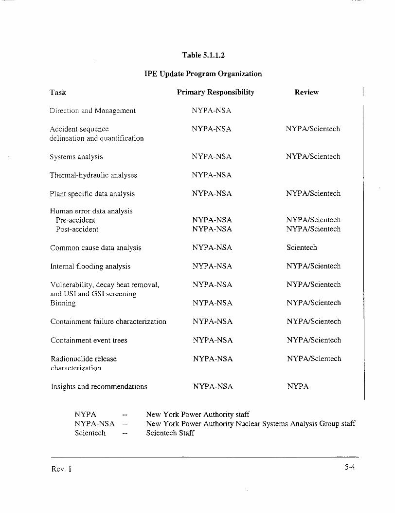
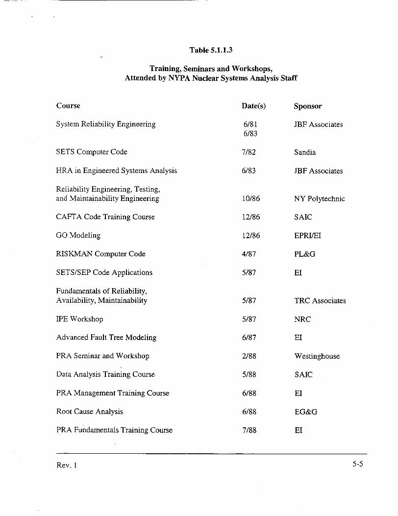


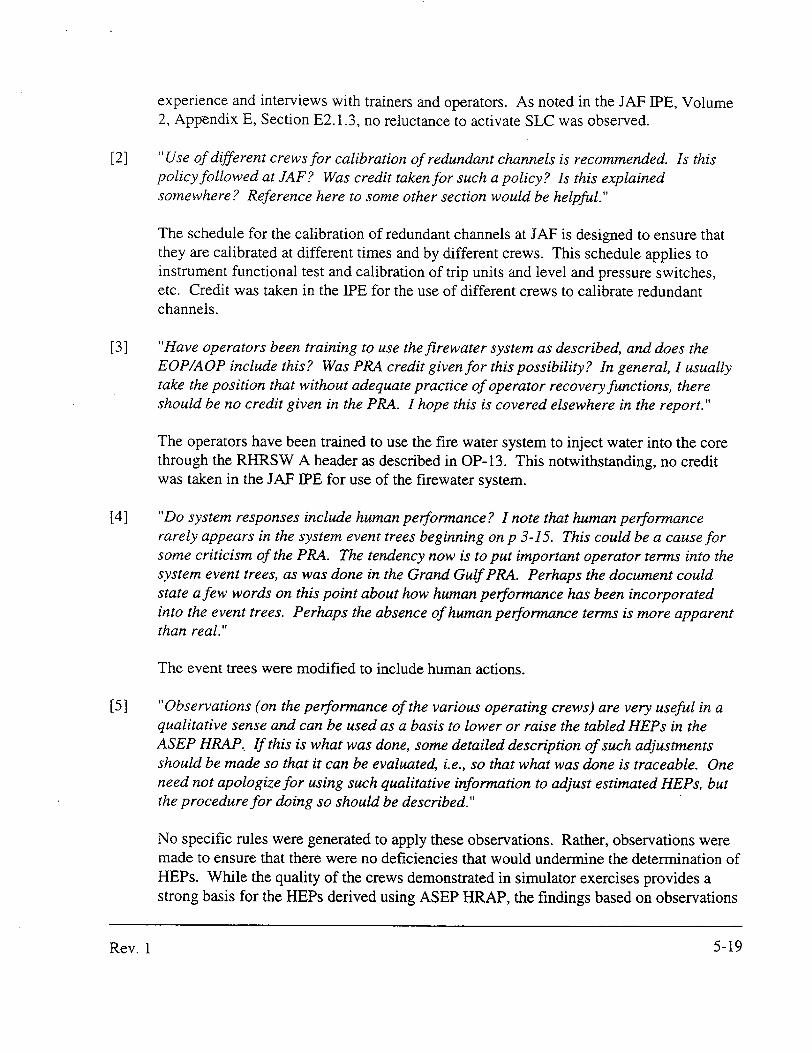


![[Update1] Ramadan Dialogue](https://static.documents.pub/doc/80x56/577cc74d1a28aba711a09749/update1-ramadan-dialogue.jpg)


