Abstract: This paper proposes a new analytical thermal resistance model which provides a specific temperature estimation for integrated power modules. Unlike the conventional two-resistor compact model, two case nodes are introduced into the proposed model to reflect the temperatures of junction and inductor. Multiple heat sources are also included in the model. FEA simulation is applied to evaluate the thermal model and verify that the accuracy of junction temperature estimation is significantly improved. It is noted that reducing thermal resistance between the junction and IC top case node can significantly enhance the cooling performance, which enables flexible methods to modify the thermal performance.
I. INTRODUCTION
Integrated power modules featuring high efficiency, high power density and high reliability are widely demanded in computer server, telecommunication equipment and industrial applications. For instance, Buck converters shown in Fig. 1 are one of the most commonly used power electronic products [1] [2]. A power module integrates the function of a Buck regulator, several auxiliary components and an inductor in one small package. The input range of these converters ranges from 5V to 48V, the output voltage can be 0.6V to 12V, and the maximum output current can be up to 50A. [3] Generally, as the output power of a module increases, larger footprint or heat sinks are required in order to provide more cooling paths. Thermal modeling is an effective method to provide an advisable mechanical dimension and verify whether the power module is over heated at full load. Thermal performance of the products affect not only the performances but also the reliability. Especially for the power modules using state of art technologies offer increasing power densities, thermal
management becomes a significant design challenge. As a consequence, thermal evaluation is a critical issue.
The most straightforward and commonly used method is the thermal equivalent circuit model. It introduces resistors and capacitors to simulate thermal resistances and capacities. The ambient temperature is modeled as a voltage source and power losses are modeled as current sources. The Two-resistor compact model shown in Fig. 2 can be applied to almost any IC or power module to estimate the thermal performance. The junction to case thermal resistance (θJC) and junction to ambient resistance (θJA) are critical parameters that enable the estimation of junction temperature [4] [5]. The thermal resistance values can be found in the datasheet and the junction temperature can be simply calculated as long as the heat dissipation is obtained. Methods such as thermal simulation and temperature sensing are utilized in addition to modelling to assist in thermal analysis [6]-[10]. However, these thermal resistances are only suitable to describe the thermal characteristics of
normal ICs which are in compact package with only one heat source, or the small packages where the temperature is almost evenly distributed on the surfaces. For the power modules or integrated multi-phase converters with more than one source of heat, each heat source has an impact on the others and the distribution of heat dissipation is not uniform. Thus the temperature rise of the case and junction are not always the same.
In this paper, a modified thermal resistance model with multiple case nodes is proposed. This model can be utilized to calculate the thermal performance of the integrated power module and evaluate thermal designs based on different structures and material. ANSYS FEA (Finite Element Analysis) is also applied to verify the accuracy of the thermal model and provide a more detailed thermal evaluation. The paper is organized as follows: Section II describes the theory of the modified thermal model and presents a typical model of power module, Section III shows the idea of the thermal model based on unique structure of power modules, i.e. 3D power modules in this paper. Section IV presents the FEA simulation results and the experimental results. Section V concludes the paper.
II. PRINCIPLE OF THE PROPOSED THERMAL MODEL
Fig. 3 illustrates an isometric drawing of a typical Power Supply in Inductor (PSI2) power module. The power module consists of one voltage regulator (including two switches and a controller), one inductor and several auxiliary components, the case is replaced by a magnetic core in order to improve the thermal performance and efficiency [11]-[15]. The size of the power module is 15mm*9mm, which is much larger than the voltage regulator itself. With two different amount of power losses in IC and inductor, the temperature will not distribute uniformly. The concept of the proposed thermal resistance model is illustrated in Fig. 4, the inductor winding is modelled as the second heat source and two more paths of heat transfer are added into the model. In order to describe the junction temperature more precisely, two direct case nodes (IC top case node and inductor top case node) are used to model the junction to case node. The IC top case node is the closest point to the regulator on the case and it reflects the junction temperature directly. These two nodes can provide a more reliable estimation of the IC and inductor winding temperatures. R_CA1 represents the IC top case node to ambient thermal resistance and R_CA2 is the inductor case node to ambient thermal resistance. One more thermal resistance R_c is added between the case nodes because the
Fig. 4. Modified Thermal Equivalent Circuit Model Fig. 5. Thermal Image with 2 Hot Spots
Fig. 6. Modified Thermal Equivalent Circuit Model
Fig. 7. Thermal Image with 3 Hot Spots
3107
thermal resistance of the case is not negligible and there is a temperature drop between the nodes.
In addition to the typical power module, the idea of divided heat sources and direct IC top and inductor case nodes can be applied to modeling of multi-phase Buck converters. The equivalent circuit model of a single phase power module is shown in Fig. 4, more case resistances are added into the model. Fig. 5 shows the thermal image of a normal Buck power module. Fig. 6 shows the model of a two phase integrated converter. Fig. 7 presents the actual thermal performance of a two phase Buck converter with a footprint size of 15mm*15mm, the three hot spots (two inductors and one regulator) correspond to the three case nodes in Fig. 6.
The test power module is a 7.5-28V input, 1-5V output integrated Buck converter. The operating frequency is 800 kHz and maximum output current is 8A. Thermal resistances are calculated and evaluated by ANSYS FEA simulation, and the values are listed in Table 1 as well as their physical representations. The losses are estimated at 12V input, 5V output voltage with 6A load current (#1) and 8A load current (#2), the winding loss is calculated by (1): = ( + ) ∗ (1 + ( − 25))(1)
Where α is the temperature coefficient of resistance for copper and T is the operating temperature. The core loss is a simulation result from ANSYS magnetic simulation and the regulator loss is the total loss minus the inductor losses. Generally, the equivalent circuit model uses only one resistor to represent the thermal resistance between the case and ambient, so Δ - Y transform is applied in order to combine RCA1 and RCA2 into a single resistor (only one case to ambient
resistance exists in the topology). The temperature of two case nodes can still be measured. The equivalent resistances in Fig. 8 are calculated by (2)-(4). = _ __ _ _ (2)
= _ __ _ _ (3)
= _ __ _ _ (4)
Fig. 9 and 10 shows the completed thermal models. The temperature of junction, winding, two case nodes and PCB can be easily calculated with this model. Values in Fig .9 correspond to the thermal performance with 6A load, and the loss is 1.85W in total; Fig. 10 shows the result when the load is 8A and the total loss is 4W. The results match with the measured value from IR camera closely for both load conditions. It can also be concluded that, for the above operating condition, 20% of the heat (20% of the total current in the model) dissipates through the case top so that the
Fig. 8. Δ - Y Transform of Thermal Resistances
Fig. 9. Proposed Equivalent Circuit Model with 6A Output
TABLE I: DEFINITION AND VALUES FOR THERMAL MODEL
Designator Thermal resistance/ Power loss Value R1 Equivalent thermal resistance (Δ-Y
transform from R_C, R_CA1, R_CA2) 72K/W
R2 Equivalent thermal resistance 32K/W R3 Equivalent thermal resistance 32K/W R4 Contact thermal resistance from the
regulator IC to the case 120K/W
R5 Joints from the regulator to the substrate
16K/W
R6 Thermal resistance between the coil and the magnetic material case 1.2K/W
R7 Joints thermal resistance from the pin of the coil to the substrate
28K/W
R8 Joints thermal resistance, from the substrate to the host board
1.5K/W
R9 Thermal board resistance from the top of the host thermal board to ambient 14K/W
R10 Resistance from case to board 205K/W P1 First power dissipation by regulator
loss 1.14
(2.70)W P2 Second power dissipation by core loss 0.164
(0.22)W P3 Third power dissipation by winding
loss 0.54
(1.10)W T1,T2 Ambient temperature 22°C
3108
junction to case top thermal resistance has a considerable impact.
III. MODIFICATION ON 3D POWER MODULES
This section utlizes the modified analytical model to analyze 3D power modules and explores the impact of several fators on thermal performance. 3D power modules feature high power density and many other advantages, but require more on thermal management [16]-[21]. Fig. 11 and 12 show the mechanical structures of a PSI2 3D power module and a plastic molded power module respectively. Compared with the conventional plastic molded power module, the PSI2 power module envolopes the voltage regultor and several auxilary componets with the Inductor, which also serves as the case of the whole integrated power module. According to the convection law (5-8), thermal resistance is determined by the thermal conductivity of path material, so the resistance will be decreased by 4 times since the thermal conductivity of magnetic core (3W/k.m) is 3-4 times larger than normal plastic material (0.7~1W/k.m). ∆ = ∗ (5) = + (6) = ∗ ∗ (7) = 1ℎ∗ (8)
The 3D power module integrates the inducator winding and IC together, therefore only one hot spot exists on the module top case. The inductor winding is on the top part of the module and it heats the case up, thus the tempearture of top case can only indicate the thermal performance of the winding. Based on the idea of sperating heat sources and adding extra nodes inside the module, the 3D analytical model introduces a thermal resistance (R4 in the topology) which is added between the IC and the winding on the top in order to estimate the tempearture more accurately.
Fig. 10. Proposed Equivalent Circuit Model with 8A Output
Fig. 11. Sturcture of 3D PSI2 Power Module
Fig. 12. Sturcture of 3D Plastic Molded Power Module
TABLE II: DEFINITION AND VALUES FOR THERMAL MODEL
Designator Thermal Resistance IPM PPM R1 Total case to ambient
thermal resistance 142K/W 155K/W
R2 Junction through the walls to top case
77K/W 320K/W
R3 Between coil & core 9K/W 14.5K/W R4 Contact resistance from
the IC to the inductor 12K/W 111K/W
R5 Joints from the IC to the substrate
14K/W 15.5K/W
R6 Resistance from coil winding to the substrate
6.5K/W 19.5K/W
R7 Joints thermal resistance from the module to PCB
3.5K/W 3.5K/W
R8 From the top of host board to ambient
17K/W 17K/W
Rx Thermal resistance from inductor core to case
1K/W 21K/W
P1 Regulator loss 1.15W 1.15W
P2 Core loss 0.164W 0.164W
P3 Winding loss 0.54W 0.54W
3109
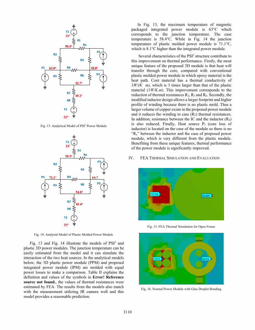
Fig. 13 and Fig. 14 illustrate the models of PSI2 and plastic 3D power modules. The junction temperature can be easily estimated from the model and it can simulate the interaction of the two heat sources. In the analytical models below, the 3D plastic power module (PPM) and proposed integrated power module (IPM) are molded with equal power losses to make a comparison. Table II explains the definition and values of the symbols in Error! Reference source not found., the values of thermal resistances were estimated by FEA. The results from the models also match with the measurement utilizing IR camera well and this model provides a reasonable prediction.
In Fig. 13, the maximum temperature of magnetic packaged integrated power module is 63°C which corresponds to the junction temperature. The case temperature is 58.4°C. While in Fig. 14 the junction temperature of plastic molded power module is 71.1°C, which is 8.1°C higher than the integrated power module.
Several characteristics of the PSI2 structure contribute to this improvement on thermal performance. Firstly, the most unique feature of the proposed 3D module is that heat will transfer through the core, compared with conventional plastic molded power module in which epoxy material is the heat path. Core material has a thermal conductivity of 3W/(K�m), which is 3 times larger than that of the plastic material (1W/K.m). This improvement corresponds to the reduction of thermal resistances R2, R5 and R6. Secondly, the modified inductor design allows a larger footprint and higher profile of winding because there is no plastic mold. Thus a larger volume of copper exists in the proposed power module and it reduces the winding to case (R3) thermal resistances. In addition, resistance between the IC and the inductor (R4) is also reduced. Finally, Heat source P2 (core loss of inductor) is located on the case of the module so there is no “Rx” between the inductor and the case of proposed power module, which is very different from the plastic module. Benefiting from these unique features, thermal performance of the power module is significantly improved.
IV. FEA THERMAL SIMULATION AND EVALUATION
Fig. 13. Analytical Model of PSI2 Power Module
Fig. 14. Analytial Model of Plastic Molded Power Module
Fig. 15. FEA Thermal Simulation for Open Frame
Fig. 16. Normal Power Module with Glue Droplet Bonding
3110
This section utilizes ANSYS FEA simulation to verify the accuracy of the proposed thermal model at different load conditions. Several cases with various potting material inside the cavity of inductor are also executed. FEA simulation is one of the most effective methods to evaluate the thermal performance of power modules and verify the thermal analysis. It provides very detailed temperature images but
requires complex mechanical models and usually takes a long time. According to the simulation, the maximum temperature of the power module under 12V input, 5V output and 8A load condition is 110.7°C. The thermal shut down condition is also simulated and the hottest point is 152.0°C. The estimation of junction temperature from the analytical model are 107.8°C and 148.4°C respectively. The loss of regulator changes from 2.68W, under normal operating conditions, to 4W, at the shutdown condition, and the junction to IC top case node temperature difference rises from 29°C to 44°C according to the FEA simulation, which is in direct proportion to the loss.
Using the modified thermal model, the thermal design of power modules can be evaluated more efficiently. For the target power module, it requires a wide input range (7.5 to 28V) and moderate output current (8A). Thus, for this module, the IC loss represents the largest power loss. Therefore, cooling of the whole module can be significantly improved by reducing the resistance between the regulator and IC top case node, which can be realized by improving the thermal conductivity between the IC and the case. On the other hand, for high output current power modules, the inductor loss will dominate the total loss. Thus reducing the inductor to case thermal resistance is more effective for those kind of modules.
A series of FEA simulations were executed to evaluate the impact of thermal resistance on the regulator side. For the PSI2 power modules, there is a cavity inside the inductor and the voltage regulator is located in this cavity. Different bonding methods and potting material will result in different regulator to IC top case thermal resistance. As shown in Fig. 15-18, four cases are analyzed: Fig. 15 shows an open frame
Fig. 17. Power Module Filled with Glue
Fig. 18. CAD Drawing of the Target Power Module
TABLE III. COMPARISON OF DIFFERENT 3D CONFIGURATIONS
Variables The open frame version
Normal glue droplet
Silicone glue droplet
Filled with thermal paste
R4(K/W) NA 120 60 25 R5(K/W) 16 16 16 15
Junction temperature in analytical model(°C) NA 107.3 104.9 100.5
Junction temperature in FEA simulation(°C) 115.6 110.7 106.7 99.8
Fig. 19 (a) Temperature versus junction to case resistance (b) Temperature versus Inductor to Case Resistance
90
95
100
105
110
160 140 120 100 80 60 40 20
Tem
pera
ture
(°C
)
Junction to case resistance (K/W)
Impact on regulator side
Junction temperature
Case Temperature
80
85
90
95
100
105
110
70 60 50 40 30 20 10 1
Tem
pera
ture
(°C
)
Inductor to case resistance (K/W)
Impact on inductor side
junction temperature
Case temperature
3111
power module whose regulator and case are contactless; in Fig. 16 the regulator is bonded to the case by glue droplets (with a thermal conductivity of 0.26W/K.m); in Fig. 17 the regulator is bonded to the case by glue with higher thermal conductivity (2W/K.m) and in Fig.18 the cavity is filled with high thermal conduct glue which envelopes the whole regulator. Table III presents the simulation results in comparison to the analytical model. Among the four conditions, open frame power module has the worst thermal performance. The maximum temperature inside the power module is reduced by 10°C from Fig .16 to Fig. 18 only by increasing the junction to IC top case thermal conductivity. Fig. 19 summarizes the results of the analytical model and also shows the results of the calculation performed for the inductor side.
A series of experiments were conducted on the target prototype. A hole was drilled in the top of power module and both thermal images from IR camera and measurement from thermocouples were used to measure the temperature. Fig. 20 shows the thermal image under the same operating conditions as the simulation. The maximum temperature of the regulator is 109°C. Thermal paste was injected into the hole to fill the cavity of the case and according to the thermal image in Fig. 20 and 21, the maximum case temperature is the same but the IC top case node temperature is higher. A thermocouple is used to measure the temperature inside the cavity and the result is 100°C, which also matches the simulation.
V. CONCLUSION
This paper proposes a modified analytical thermal equivalent circuit model to help with thermal management design of multiple-heat sources devices in the power modules. This model explores the use of additional nodes to describe the temperature of IC and inductor respectively and it can reduce the error of junction temperature estimation. Another model approaching the thermal performance of 3D power modules is also presented. Based on calculations using the modified thermal model the thermal resistance on the regulator side plays an important role in cooling performance. In an experiment performed with a test prototype module, the temperature is reduced by 10°C
through improving the thermal contact between the IC and the case. Further analysis on optimizing the structure, material and inductor based on the proposed model to achieve better thermal performance will be the future work.
Industrial and lab-scale power module technologies: A review. In IEEE Industrial Electronics, IECON 2006-32nd Annual
[2] Skoplaki, E., & Palyvos, J. A. (2009). On the temperature dependence of photovoltaic module electrical performance: A review of efficiency/power correlations. Solar energy, 83(5), 614-624.
[3] Cooper, David. "Power Module Integration: A new approach." IEEE Power Electronics Magazine 3.3 (2016): 31-36.
[4] JEDEC standard: Jesd 51 “ Methodology for the thermal measurement of component packages ” , JEDEC solid state technology association.
[6] Takahashi, Tomohiro, and Q. Yu. "Precision evaluation for thermal fatigue life of power module using coupled electrical-thermal-mechanical analysis." Electronics Packaging Technology Conference (EPTC), 2010 12th IEEE, 2010:201-205.
[7] Hirohata, K., Hisano, K., Mukai, M., Aoki, H., Takubo, C., Kawakami, T., & Pecht, M. G. (2010). Coupled thermal-stress analysis for FC-BGA packaging reliability design. Components and Packaging Technologies, IEEE Transactions on, 33(2), 347-358.
[8] Yamada, Y., Yu, Q., Takahashi, T., & Takagi, Y. (2012, December). Study on thermal design due to downsizing of power module using coupled electrical-thermal-mechanical analysis. In Electronic Materials and Packaging (EMAP), 2012 14th International Conference on (pp. 1-7). IEEE.
[9] Ménager, L., Martin, C., Allard, B., & Bley, V. (2006, November). Industrial and lab-scale power module technologies: A review. In IEEE Industrial Electronics, IECON 2006-32nd Annual Conference on (pp. 2426-2431). IEEE.
[10] Liu, Tianshu, et al. "A novel asymmetrical three-level BUCK (ATL BUCK) converter for point-of-load (POL) application." Energy Conversion Congress and Exposition (ECCE), 2015 IEEE, 2015.
[11] Laili Wang, W. Liu, D. Malcolm and Y-F. Liu. "Thermal Analysis of a Magnetic Packaged Power Module" Applied Power Electronics Conference and Exposition, 2016. APEC 2016. Thirty-first Annual IEEE, 2016.
[12] Laili Wang, D. Malcolm and Y-F. Liu. "An Innovative Power Module with Power-System-In-Inductor Structure" Applied Power Electronics Conference and Exposition, 2016. APEC 2016. Thirty-first Annual IEEE, 2016
Fig. 20 Thermal Image Normal Glue Bonding Fig. 21 Power Module Filled with Thermal Paste
Regulator109°C
Case 89°C
IC top 85°C
Case 91°C
3112
[13] Wang, L., Hu, Z., Liu, Y. F., Pei, Y., Yang, X., & Wang, Z. (2013). A Horizontal-Winding Multipermeability LTCC Inductor for a Low-profile Hybrid DC/DC Converter. Power Electronics, IEEE Transactions on, 28(9), 4365-4375.
[14] Wang, L., Hu, Z., Qiu, Y., Wang, H., & Liu, Y. F. (2014, March). A new model for designing multi-hole multi-permeability nonlinear LTCC inductors. In Applied Power Electronics Conference and Exposition (APEC), 2014 Twenty-Ninth Annual IEEE (pp. 757-762). IEEE.
[15] Wang, L., Hu, Z., Liu, Y. F., Pei, Y., & Yang, X. (2013). Multi-permeability Inductors for Increasing the Inductance and Improving the Efficiency of High-Frequency DC/DC Converters. Power Electronics, IEEE Transactions on, 28(9), 4402-4413.
[16] Davis, W.R., Wilson, J., Mick, S., Xu, J., Hua, H., Mineo, C., Sule, A.M., Steer, M. and Franzon, P.D., 2005. Demystifying 3D ICs: the pros and cons of going vertical. Design & Test of Computers, IEEE, 22(6), pp.498-510.
[17] Hirohata, K., Hisano, K., Mukai, M., Aoki, H., Takubo, C., Kawakami, T., & Pecht, M. G. (2010). Coupled thermal-stress analysis for FC-BGA packaging reliability design. Components and Packaging Technologies, IEEE Transactions on, 33(2), 347-358.
[18] Yamada, Y., Yu, Q., Takahashi, T., & Takagi, Y. (2012, December). Study on thermal design due to downsizing of power module using coupled electrical-thermal-mechanical analysis. In Electronic Materials and Packaging (EMAP), 2012 14th International Conference on (pp. 1-7). IEEE.
[19] Lan, Jia Shen, and M. L. Wu. "An analytical model for thermal failure analysis of 3D IC packaging." Thermal, mechanical and multi-physics simulation and experiments in microelectronics and microsystems (EuroSime), 2014 15th international conference on IEEE, 2014:1-5.
[20] Hirohata, K., Hisano, K., Mukai, M., Aoki, H., Takubo, C., Kawakami, T., & Pecht, M. G. (2010). Coupled thermal-stress analysis for FC-BGA packaging reliability design. Components and Packaging Technologies, IEEE Transactions on, 33 (2), 347-358.
[21] Yamada, Y., Yu, Q., Takahashi, T., & Takagi, Y. (2012, December). Study on thermal design due to downsizing of power module using coupled electrical-thermal-mechanical analysis. InElectronic Materials and Packaging (EMAP), 2012 14th International Conference on (pp. 1-7). IEEE.