Texas A&M University Mechanical Engineering Department Turbomachinery laboratory A Novel FE Bulk-Flow Model Improving Predictions of Force Coefficients in Off-Centered Grooved Oil Seals Research Progress Report to the Turbomachinery Research Consortium TRC- SEAL-1-08 Adolfo Delgado Research Assistant Luis San Andrés Mast-Childs Professor Principal Investigator June 2008 TEES project 32513/1519T7
Transcript
Texas A&M University Mechanical Engineering Department
Turbomachinery laboratory
A Novel FE Bulk-Flow Model Improving Predictions of Force
Coefficients in Off-Centered Grooved Oil Seals
Research Progress Report to the Turbomachinery Research Consortium
TRC- SEAL-1-08
Adolfo Delgado Research Assistant
Luis San Andrés
Mast-Childs Professor Principal Investigator
June 2008
TEES project 32513/1519T7
TRC- SEAL-1-08 2
Executive Summary
TRC-Seal-1-08 A Novel FE Bulk-Flow Model Improving Predictions of Force Coefficients in Off-Centered
Grooved Oil Seals
Oil seals in centrifugal compressors reduce leakage of the process gas into the support
bearings and ambient. Under certain operating conditions of speed and pressure, oil seals
lock, becoming a source of hydrodynamic instability due to excessively large cross
coupled stiffness coefficients. It is a common practice to machine circumferential grooves,
breaking the seal land, to isolate shear flow induced film pressures in contiguous lands,
and hence reducing the seal cross coupled stiffnesses. Exhaustive oil seal testing
performed by Childs and students shows that an inner land groove, shallow or deep, does
not actually reduce the cross-stiffnesses as much as conventional models predict. In
addition, the tested grooved oil seals show overly large added mass coefficients; while
predictive models, based on classical lubrication theory, miss entirely the fluid inertia
effect.
A 2007 TRC report introduces a fluid inertia, bulk-flow model that properly accounts
for the flow and moment transport at the groove-land interfaces. The novel model
predicts with exactness the force coefficients of multiple-groove laminar flow oil seals at
their centered condition. The analysis relies on an effective groove depth, different from
the physical groove depth, which delimits the upper boundary for the flow induced by
dynamic (fluid squeezing) motions in the grooved region of a seal.
The current report extends the bulk-flow analysis to predict the leakage, reaction
forces and dynamic force coefficients of grooved oil seals operating at an off-centered
(eccentric) locked condition. Predictions of rotordynamic force coefficients are compared
to published test coefficients for a smooth land seal and a seal with a single groove seal
with a depth of 15 times the land clearance (c=85.9 μm). The test data represents
operation at 10 krpm and 70 bar oil feed pressure, and four journal eccentricity ratios
(e/c= 0, 0.3, 0.5, 0.7). The enhanced model predicts accurately the smooth and grooved
seals’ leakage, reaction force, and rotordynamic force coefficients for the lowest
eccentricities (e/c= 0, 0.3). The model yields moderate to good correlation with the test
force coefficients for e/c=0.5. For the largest journal eccentricity, e/c=0.7, significant
discrepancies between the predictions and experimental results arise. The test data
TRC- SEAL-1-08 3
technical report does not offer details on operating conditions leading to large power
dissipation that may have affected the lubricant properties and seal clearance.
The model completed is a significant improvement that predicts accurately the
rotordynamic force coefficients of locked multiple-grooved oil seals. Prior to the current
results, the cross-coupled stiffness coefficients of grooved oil seals were largely under
predicted, and the direct added mass coefficients ignored or largely under predicted (up
10 times). The computational tool integrates a XLTRC2 type GUI to the FEM solution of
the flow equations.
Note: The P.I. edited this report five times, English and technical content, prior to its release to TRC members.
TRC- SEAL-1-08 4
Table of Contents Executive Summary ............................................................................................................ 2
List of Tables ...................................................................................................................... 5
List of Figures ..................................................................................................................... 5
Figure 7 Graphical user interface for XLFEGLOSeal® code (SI units) .......................... 22
Figure 8 Configuration of parallel oil seals tested in Ref. [6] .......................................... 23
Figure 9 Measured journal centerline locus for smooth and grooved seal (cg =15c). (70
bar, 10000 rpm) [7] ................................................................................................... 24
Figure 10 Seal reaction forces. Experiments for smooth seal and seal with inner land
groove (cg= 15c), 10000 rpm, 70 bar [7]. Predictions for smooth seal and seal with
inner land groove (cη = 7c) ....................................................................................... 25
Figure 11 Direct stiffness coefficient (Kii) versus eccentricity. Experiments for smooth
seal and seal with inner land groove (cg= 15c), 10000 rpm, 70 bar [7]. Predictions
for smooth seal and seal with inner land groove (cη = 7c)........................................ 26
Figure 12 Cross-coupled stiffness coefficients (Kij) versus eccentricity. Experiments for
smooth seal and seal with inner land groove (cg= 15c), 10000 rpm, 70 bar [7].
Predictions for smooth seal and seal with inner land groove (cη = 7c)..................... 27
Figure 13 Cross-coupled stiffness coefficients (Kxy) versus shaft speed at two journal
eccentricities (0, 0.3). Experiments for smooth seal and seal with inner land groove
TRC- SEAL-1-08 6
(cg= 15c), 10000 rpm, 70 bar [7]. Predictions for smooth seal and seal with inner
land groove (cη = 7c)................................................................................................. 28
Figure 14 Direct damping coefficients (Cii) versus eccentricity. Experiments for smooth
seal and seal with inner land groove (cg= 15c), 10000 rpm, 70 bar [7]. Predictions
for smooth seal and seal with inner land groove (cη = 7c)........................................ 29
Figure 15 Cross-coupled damping coefficients (Cij) versus eccentricity. Experiments for
smooth seal and seal with inner land groove (cg= 15c), 10000 rpm, 70 bar [7].
Predictions for smooth seal and seal with inner land groove (cη = 7c)..................... 30
Figure 16 Added Mass coefficient (Mxx, Myy) versus eccentricity. Experiments for smooth
seal and seal with inner land groove (cg= 15c), 10000 rpm, 70 bar [7]. Predictions
for smooth seal and seal with inner land groove using (cη = 7c).............................. 31
Figure 17 Seal leakage versus eccentricity. Experiments for smooth seal and seal with
inner land groove (cg= 15c), 10000 rpm, 70 bar [7]. Predictions for smooth seal and
seal with inner land groove using (cη = 7c) .............................................................. 32
TRC- SEAL-1-08 7
Nomenclature Cij Direct damping coefficients [N.s/m] i,j=x,y c Clearance [m] cη Characteristic clearance [m]
dη Characteristic groove depth [m]
e0 Journal eccentricity [m] h Film thickness [m] L Axial length [m] Kij Direct stiffness coefficients [N/m] i,j=x,y Mij Added mass coefficient [Kg] i,j=x,y
,x zm Mass flow rates [kg/s] N Number of flow regions in flow domain Nem Number of elements (FEM mesh) npe Number of Nodes per element (FEM mesh) P Pressure [Pa] PX,PY First-order pressure fields [Pa] i Imaginary number ( 1− ) R Journal radius [m] ReA VAcρ/μ. Axial flow Reynolds number
*Re ρωcη2/12μ. Modified squeeze film Reynolds number
s Zeroth order pressure axial gradient [Pa/m] t Time [s] Vx,Vz Bulk flow velocities [m/s] X,Y,Z Inertial coordinate system [m] x,z Circumferential and axial coordinates [m] Δe Displacement amplitude [m] ε Eccentricity ratio (e/c) μ Absolute viscosity [Pa.s] ν Kinematic viscosity [m2/s] Ω Rotor rotational speed [rad/s] ω Rotor whirling frequency [rad/s] ρ Oil density [kg/m3] θ Angular coordinate [deg] ψ Interpolation functions (FEM) Subscripts 0 Zeroth order solution exp. Derived from experiments g groove N Last annular cavity section model Derived from predictions α α-th annular cavity section σ X,Y coordinates
TRC- SEAL-1-08 8
I Introduction
Oil seals are used in centrifugal compressors to reduce leakage of the process gas into
the support oil lubricated bearings as well as into ambient [1]. An oil seal, shown in Fig.
1, comprises of a floating ring and elastic support that, under certain operation conditions,
may lock up and act as a hydrodynamic journal bearing [3]. These seals are known as
potential sources of instability due to the generation of large cross-coupled stiffnesses [1,
4]. A common practice to minimize the destabilizing effect of oil seals is to machine
circumferential grooves to isolate and divide the seal land into shorter length lands, thus
reducing the hydrodynamic fluid film forces. To date, there are major discrepancies
between predicted and experimental force coefficients obtained for grooved seals.
Experimental results detailed in Refs. [1, 6, 7] show that incorporating circumferential
grooves do reduce cross-coupled force coefficients but to a lesser extent than predictions
otherwise indicate. Furthermore, experimental added mass coefficients are found to be
very large and not modeled in common predictive tools.
Figure 1 Oil seal ring assembly, Ref. [2]
A prior TRC report [8] introduces a novel analysis to obtain the force coefficients of
centered grooved oil seals. The bulk-flow formulation determines seal force coefficients
from an amplitude perturbation analysis about a centered position. Extending the original
bulk flow analysis, this report details the implementation of a finite element method to
obtain the oil seal force coefficient for journal (rotor) off-centered conditions.
TRC- SEAL-1-08 9
The following review presents the analytical and experimental work on laminar-flow
grooved oil seals.
II Literature Review
The archival literature for laminar flow oil grooved seals is rather scant [1,9]. Most of
the work has been conducted to analyze turbulent flow annular pressure seals typical in
high pressure compressors and pumps [9]. This literature review includes the current
available computational tools and experimental results valid for laminar-flow grooved oil
seals, i.e. axial flow Reynolds number (ReA=Va*c/ν) ≤ 2000, with Va as the axial mean
flow velocity, c as the film clearance, and ν is the kinematic viscosity.
Analytical work Semanate and San Andrés [3] present an isoviscous bulk flow analysis to predict
force coefficients of a grooved oil seal operating under either laminar or turbulent flow
regimes and not accounting for fluid inertia terms. The analysis includes surface
roughness, fluid inertia and viscous effects at the seal inlet plane, and variable clearance
(i.e. tapered seal). The bulk flow equations are solved for small amplitude motions using
a perturbation analysis and an iterative finite difference scheme. The force coefficients
are presented in terms of the ring eccentricity ratio for three cases: single land, two lands
and three lands. The numerical results indicate that both the cross-coupled stiffnesses and
direct damping coefficients are substantially reduced. These findings imply that the
grooves effectively separate the seal lands, thus reducing the seal force coefficients.
However, the whirl frequency ratio (WFR), a stability indicator, remains relatively
constant, and thus there is not significant improvement of the seal rotordynamic stability
characteristics. Regarding the entrance effects due to viscous and inertia effects, the
predictions indicate that such effects are of importance only for high pressure
applications.
Baheti and Kirk [4] analyze the dynamic forced response of grooved oil seals
including thermal effects but still neglecting fluid inertia. The coupled pressure and
temperature transport equations, developed in terms of a perturbation analysis for small
amplitude journal motions, are modeled with a finite element scheme. The study includes
arc and square groove geometries located at the seal mid-land length. The numerical
TRC- SEAL-1-08 10
results show a reduction of 40% in the direct damping and cross-coupled stiffness
coefficients of an oil seal when including a square groove with a groove depth to
clearance ratio (dg/c) equal to 6. On the other hand, when using a deeper groove (dg/c =
15) the force coefficients are reduced by a factor of 4 by adding a single groove, and by
10 when adding two grooves. Thus, for the latter case, the results indicate that an inner
groove effectively isolates the pressure distribution of contiguous film lands.
San Andrés and Delgado [8] present a bulk-flow fluid inertia analysis to predict the
force coefficients of grooved oils seals and squeeze film dampers operating at their
centered position. A perturbation analysis yields zeroth and first order flow equations at
each individual flow region (land and grooves) of constant clearance ( c ). The authors
present an analytical solution for circular centered journal orbits of small amplitude. The
model relies on defining an effective groove depth that represents the actual upper
boundary of the dynamic (squeeze) flow. A parametric study using multiple effective
groove depths (dη) show that there is an excellent correlation between the predicted and
experimental force coefficients of a grooved oil seal [6] for a narrow range of effective
groove depths. Specifically, for a short length and shallow groove at the mid-land of the
seal, predictions of added mass, cross-coupled stiffness, and damping coefficients
correlate best with experimental data [6] when using a fraction (50% or less) of the actual
groove depth. Most importantly, the predictions demonstrate that the inner groove in the
oil seal does not isolate the adjacent film lands.
Experimental work Childs et al. [1] identify experimentally the rotordynamic force coefficients and
measure the leakage of smooth land and grooved oil seals operating under laminar flow
conditions. The authors aim to quantify the influence of inner-land grooves on the
rotordynamic coefficients of oil seals and to evaluate the accuracy of existing predictive
models. Ref. [1] includes a detailed description of smooth and grooved oil seals and their
operating features, and a comprehensive literature review of prior work conducted on oil
seals operating in the laminar flow regime. Particularly, the authors indicate that, prior to
their publication, the only published experimental work on laminar-flow oil seals was
conducted by Kaneko [10] on smooth land seals. In Ref. [1], static and dynamic force
coefficients are identified for a smooth seal, a 1-groove seal, and a 3-groove seal (with
dg/c = 6). The experimental force coefficients for the smooth seal correlate well with
TRC- SEAL-1-08 11
predictions from an annular seal model given in Ref. [11], except for the added mass
coefficient that the analysis underestimates by a factor of about 10. The authors note that
the large volume of the oil supply central groove may explain the large discrepancy.
However, pressure measurements at both the feed groove and exit cavity show no
dynamic pressure oscillations. The experimental force coefficients for the grooved oil
seals are largely underestimated by the model of Semanate and San Andrés [3]. The test
results suggest that, contrary to the accepted assumptions, inner-land grooves are not
deep enough to isolate the hydrodynamic pressures from contiguous seal film lands.
Childs et al. [6] present experimental results evidencing the effect of groove depth on
the dynamic force response and leakage of a test oil seal. Rotordynamic force coefficients
are identified for four seals, including a smooth land seal and three seals with a single
groove at the middle of the land. The three grooved seals present different groove depth
to clearance ratios; dg/c = 5, 10, and 15. The identified seal force coefficients and leakage
are presented as a function of the seal journal eccentricity for three speeds and three oil
supply pressures. The test results indicate that the seal force coefficients decrease as the
groove depth increases, except for the added mass coefficients. However, predictions
based on Ref. [3] largely underestimate the grooved seal oil cross-coupled stiffnesses and
direct damping coefficients even for the test seal with the deepest groove. Thus, the
experiments reveal that, even for a groove depth to clearance ratio as large as 15, a
groove does not completely isolate the hydrodynamic pressures of the two adjacent seal
lands (i.e. for the cross-coupled stiffness coefficients: Kxy (2 lands) ≠ ¼ Kxy (1 land), and
the direct damping coefficients: Cxx(2 lands) ≠ ¼ Cxx(1 land) as predictions reported in [3].
In addition, the experimental results also show relatively large added mass coefficients
that increase as the groove depth increases. However, a prediction of added mass
coefficient, based on a classical lubrication model [12], yields only 2.8 kg (i.e. 10 times
smaller than the experimental value). On the other hand, the predicted added mass
coefficients obtained with the novel model in Ref.[8] show a remarkable correlation with
the test data.
III Analysis
The literature review reveals the need for an improved model that properly predicts
the force coefficients of a (laminar flow) grooved ring seal for eccentric journal operation.
TRC- SEAL-1-08 12
This deficiency is addressed by updating the bulk flow model advanced in Ref. [8] for
off-centered journal operation using a finite element analysis. The derivation of the bulk
flow equation for the oil seal follows.
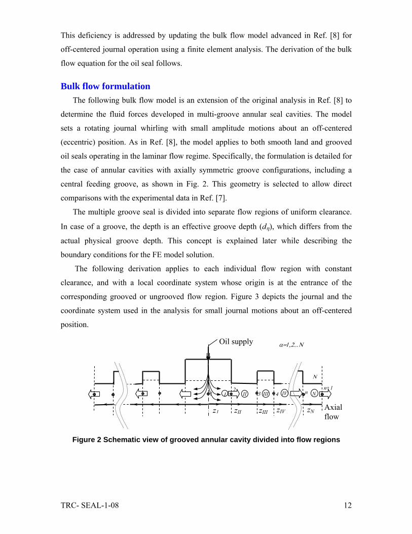
Bulk flow formulation The following bulk flow model is an extension of the original analysis in Ref. [8] to
determine the fluid forces developed in multi-groove annular seal cavities. The model
sets a rotating journal whirling with small amplitude motions about an off-centered
(eccentric) position. As in Ref. [8], the model applies to both smooth land and grooved
oil seals operating in the laminar flow regime. Specifically, the formulation is detailed for
the case of annular cavities with axially symmetric groove configurations, including a
central feeding groove, as shown in Fig. 2. This geometry is selected to allow direct
comparisons with the experimental data in Ref. [7].
The multiple groove seal is divided into separate flow regions of uniform clearance.
In case of a groove, the depth is an effective groove depth (dη), which differs from the
actual physical groove depth. This concept is explained later while describing the
boundary conditions for the FE model solution.
The following derivation applies to each individual flow region with constant
clearance, and with a local coordinate system whose origin is at the entrance of the
corresponding grooved or ungrooved flow region. Figure 3 depicts the journal and the
coordinate system used in the analysis for small journal motions about an off-centered
position.
Figure 2 Schematic view of grooved annular cavity divided into flow regions
Oil supply
n+1
z1 zIII zII zIV
12
3 4
zN
n I II III IV
Ν
N
α=1,2...Ν
Axial flow
TRC- SEAL-1-08 13
Figure 3 View of rotating and whirling journal and coordinate system for bulk-flow
analysis
Within each individual flow region the mass flow rates in the circumferential (x) and
axial (z) directions are:
;x x z zm h V m h V
α α α αα αρ ρ= = , ,...I II Nα = (1) where hα is the film thickness, ( ,x zV V
α α) are bulk-flow velocities in each flow region α,
and ρ is the lubricant density.
The bulk-flow continuity and moment transport equations without fluid advection
terms are [13]:
( ) ( ) ( ) 0x zm m hx z tα α α
α
ρ∂ ∂ ∂+ + =
∂ ∂ ∂ (2)
( )
2x
x x
mP Rh k Vx h t
α
α
αα
α
μ ∂∂ Ω⎛ ⎞− = − +⎜ ⎟∂ ∂⎝ ⎠ (3)
( )zz
z
mVPh kz h t
αααα
α α
μ∂∂
− = +∂ ∂
; , ,...I II Nα = (4)
x= θR
Y
X
Δe
ω
h Ω
R
Ω= rotational speed
Δe= journal displacement ω= whirl frequency
exo
eyo
journal
TRC- SEAL-1-08 14
with kx=kz=12 for laminar flow. Above, μ is the lubricant viscosity and Pα is the pressure
at each flow region. Equations (3) and (4) are rewritten as:
( )
( )
3 2
3 2
;2
; , ,...
xx
x x
zz
z z
mh P h h Rmk x k t
mh P hm I II Nk z k t
α
α
α
α
α α α α
α α α
α
ρ ρ ρμ μ
ρ ρ αμ μ
∂∂ Ω= − − +
∂ ∂
∂∂= − − =
∂ ∂
(5)
Differentiating xm
α with respect to x, and zm
α with respect to zα, adding both
equations, and disregarding second order terms yields a Reynolds-like equation for the
The journal describes motions of small amplitude (ΔeX , ΔeY )<< c αη and frequency
ω about an static position (eXo, eYo). The film thickness (hα) equals [13]
{ }0 0cos sin ; 1; ,
, ,...
i t i tX Yh = h + e ( ) + e ( ) h + e h i = X Ye e
I II Nα α
ω ωα σ σθ θ σ
α
Δ Δ = Δ − =
= (7)
with ( ) ( )
00 cos sinX Yh c e e c e hα α αη η σ σθ θ= + + = + ; ( ) ( )cos , sinX Yh hθ θ= = (8)
and ( )αα ηη dcc += is the effective clearance over the grooved flow regions. Note that
αηd
is the effective groove depth, and c cαη = in an ungrooved (seal land) flow region. The
pressure is expressed as a superposition of a zeroth order field (Po) and first order
(dynamic) fields ( ,X YP Pα α
)
0 ; , ,...i tP = P + e P I II Neα α
ωα σ σ αΔ = (9)
Substitution of Eqs. (7) and (9), into Eq. (6) gives the zeroth order equations for the
equilibrium pressure
TRC- SEAL-1-08 15
( )0 03 30 0 06
, ,...
P Ph h R h
x x z z xI II N
α α
α α αα α
μ
α
∂ ∂⎛ ⎞ ⎛ ⎞∂ ∂ ∂+ = Ω⎜ ⎟ ⎜ ⎟∂ ∂ ∂ ∂ ∂⎝ ⎠ ⎝ ⎠
=
(10)
and the first order equations for journal dynamic displacements along the X and Y directions
{ }3 3*
0 02 20 0
12 1 Re 6
- 3 3 ;
, ; , ,...
P P dhh h i i h Rx x z z dx
P Ph h h h
x x z zX Y I II N
α αα
α α
α α
σ σ σα α σ
α α
σ σ
μ ω μ
σ α
∂ ∂⎛ ⎞ ⎛ ⎞∂ ∂+ = + + Ω⎜ ⎟ ⎜ ⎟∂ ∂ ∂ ∂⎝ ⎠ ⎝ ⎠
∂ ∂⎛ ⎞ ⎛ ⎞∂ ∂−⎜ ⎟ ⎜ ⎟∂ ∂ ∂ ∂⎝ ⎠ ⎝ ⎠
= =
(11)
where 2
*Re12
cα
α
ηρωμ
= is a local squeeze film Reynolds number. Once Eq. (10) and Eq.
(11) are solved, the fluid film reaction forces at a static journal position (eXo, eYo) are
0 0 , ; 1 0
; LN
X YF h P R d dzα
ασ σ α σα θ
θ ==
= ∑ ∫ ∫ (12)
The seal force coefficients are also obtained by integrating the dynamic pressure fields over the flow domain [13],
( ) ( ), , 1 0
i ; ; = cos , = sin
, ,...
LN2
X Y X Y- + h P R d dz h hCK M
I II N
α
α α α ασβ σβ σβ σ β α σ βα θ
ω θ θ θω
α
==
= −
=
∑ ∫ ∫
(13)
Finite element solution The procedure implemented for solving the Reynolds-like Eq. (11) with the finite
element method (FEM) is similar to that in Refs. [13,14]. The implementation of the
current development into a FORTRAN® code follows from modifying an existing code
that predicts force coefficient for smooth seals without including inertia effects [3].
Without loss of generality, the solution is presented for a symmetric oil seal with an inlet
groove and a single mid-land groove similar to the seal tested in Ref. [7]. A similar
solution can be applied to multi-groove seals.
TRC- SEAL-1-08 16
Following the discretization of the domain into elements ( eΩ ), as shown in Fig. 4, the
static and dynamic pressure fields are represented as the linear combination of nodal
values i
eP within each element as
YX
n
i
ei
en
i
ei
epe
i
pe
iPPPP ,
1100 ; , =
==∑∑ Ψ=Ψ= σσσ (11)
where ψe are bilinear interpolation functions. The equation to be solved for each element
follows from the representation of the fluid differential equations (10, 11) in its
variational or weak form [13] using the interpolation functions as weight functions.
`
Figure 4 Coordinate system and sample mesh for oil seal FEM computational code
The weak variational form of Eq. (10) for the zeroth order pressure yields
k P q fije e
j
n
ie
ie
j
pe
01=
∑ = − + (12)
with
Inlet plane
Outlet plane
θ
z
z x=θR
Grooves
0h α
eΩ
eΓ
1 2
3 4
Inlet
Outlet
2π 0P=Psupply
P=Pexit
TRC- SEAL-1-08 17
e
30
12
e ej je i i
ij
hk dx dz
x x z zα
∂ ∂∂ ∂μ ∂ ∂ ∂ ∂
Ω
⎛ ⎞ Ψ Ψ⎧ ⎫Ψ Ψ= +⎜ ⎟ ⎨ ⎬⎜ ⎟ ⎩ ⎭⎝ ⎠
∫∫ (13)
e0 0
2i
ee iRf h dx dz
xα
∂∂Ω
ΨΩ= ∫∫ (14)
00ie
e e ei nq q d
Γ
= Ψ Γ∫ ; with 0
30 00
12 2n x
h h RPq nn
α α∂μ ∂
Ω= − + (15)
Similarly for the first order perturbed pressure fields, PX and PY, the set of equations
for the nodal pressures in a finite element are
0 , 1 1
; pe pe
j i ij j i
n ne e e e e eij X Y
j jk P f S P qσ σ σ σ σ =
= =
= − −∑ ∑ (16)
where
e e
220
2 12i
ee e ei
i iRf h h dx dz h dx dz
x ασ σ σ∂ ρ ω ω∂ μ
Ω Ω
⎡ ⎤ΨΩ ⎡ ⎤= + Ψ − Ψ⎢ ⎥ ⎣ ⎦⎣ ⎦
∫∫ ∫∫i (17)
203
12ij
e
e ej je i i
hS h dx dz
x x z zα
σ σ
∂ ∂∂ ∂μ ∂ ∂ ∂ ∂Ω
⎛ ⎞ Ψ Ψ⎧ ⎫Ψ Ψ= +⎜ ⎟ ⎨ ⎬⎜ ⎟ ⎩ ⎭⎝ ⎠
∫∫ (18)
ie
e e ei nq q d
σσΓ
= Ψ Γ∫ ; 3 20 0 0
312 12 2n x
h hP P Rq h h nn n
α α
σ
σσ σ
∂ ∂μ ∂ μ ∂
⎛ ⎞ Ω= − − +⎜ ⎟⎜ ⎟
⎝ ⎠ (19)
with n as the normal vector to the boundary eΓ of an element. Note that Eq. (17) includes
the temporal fluid inertia term (second term in first integral). The integrals in Eq. (13)
through Eq. (19) are evaluated numerically over a master element ( Ω̂ ) with normalized
coordinates (isoparametric element). Reddy and Gartling [15] detail the coordinate
transformation and numerical integration procedure using Gauss-Legendre quadrature
formulas.
Equations (12) and (16), for each element of the flow domain, are assembled to form
a linear system of equations represented as
TRC- SEAL-1-08 18
[ ] { } { } { }
[ ] { } { } { } [ ] { }
0
0
; : 0
; : ,
Global Global Global Global
Global Global GlobalGlobal Global Global
k P Q F
k P Q F S P X Y
γ γ
γ γ γ
γ
γ
= +
= + +
(20)
where
[ ] [ ] { } { } { } { }1 1 1
, ,Nem Nem Neme ee
Global Global Globale e e
k k Q q F fγ γ γ γ= = =
= = =∪ ∪ ∪ , γ:0,X,Y. (21)
The resulting global fluidity matrix [ ]Global
k is symmetric and can be easily
decomposed into its upper and lower triangular form, i.e.
[ ] [ ] [ ] [ ] [ ]TGGGGG LLULk == (22)
Thus, once the L, LT and F matrices are obtained, and stating the pressure at the inlet
and exit planes of the flow domain, a process of back- and forward-substitutions renders
the discrete zeroth order pressure field { }0 GP . Using the results from the fluidity matrix
and the zeroth order pressure field, the first order pressure field,{ }G
Pγ , are obtained. The
selection of the appropriate boundary conditions, based on the physics of the problem, is
essential for obtaining the force coefficients in the grooved seal geometry.
Boundary Conditions Figure 5 shows the mesh for ½ a flow domain on an oil seal with an inlet (supply)
groove and an inner groove, and the nodes of interest to enforce boundary conditions.
Both the zeroth and first order fields are periodic in the circumferential direction,
( , ) ( 2 , )P z P zγ γθ θ π= + ; γ=0, X, Y (23)
The fluid pressure must be greater than the lubricant cavitation pressure (Pcav). In the
current analysis, the Gumbel condition of oil cavitation is enforced for the zeroth and first
order pressure fields.
Note that Eqs. (15) and (19) automatically satisfy the flow continuity at the boundary
between a smooth land and groove, for example. Hence, no special considerations in
regard to flow matching are required. Other boundary conditions are:
TRC- SEAL-1-08 19
Zeroth Order Pressure Field A) Constant static pressure at inlet plane (z= 0). This condition is set to the lower
nodes of elements along the inlet plane.
0 supply e
z LP P
== (24)
B) Constant static pressure at exit plane (z= L). This condition is set to the upper
nodes of elements along the exit plane.
0 exit0
e
zP P
== (25)
Figure 5 FEM mesh depicting nodes of interest for implementation of boundary
conditions
First Order Pressure Fields A) Null dynamic pressure at exit plane (z= L). While the static pressure is constant, it
is assumed that there is not generation of dynamic pressure at the exit (discharge)
plane. This condition is set to the upper nodes of elements along the exit plane.
0 e
z LPγ =
= (26)
B) At the inlet plane (feed or supply central groove) the axial flow induced by the
dynamic (fluid squeezing) motions is set to zero due to axial symmetry.
z=0= 0
zq (27)
Pγ(θ,z)=Pγ(θ+2π,z)
Outlet plane
x
z
Groove
Groove
A
B P=Psupply Inlet plane
γ =0,x,y
P=Pexit
TRC- SEAL-1-08 20
This boundary condition implies that the “perturbed” axial flow does not cross the
middle plane and that there is a non-zero dynamic pressure field at this plane. This is a
Neumann type B.C. implemented by treating the nodes at inlet plane as internal nodes.
Effective groove depth
As advanced in Ref. [8], the laminar flow pattern at the groove is characterized by a
recirculation region and a thru flow region. These regions are divided by a stream line
that is considered to act as a physical boundary. Figure 5 shows a representation of the
streamlines pattern for a pressure driven flow through a (symmetric) annular cavity with
a supply groove and two mid-land grooves. The figure also depicts a close-up of CFD
simulations of the pressure driven flow at the mid-land groove for two groove depths
(10c and 15c). In this configuration the flow pattern at the supply and mid-land grooves is
characterized by two regions, a recirculation region and a thru flow region. Furthermore,
the dividing streamlines for the 10c and 15c groove depths present a similar penetration
depth. In the proposed analysis, the streamlines dividing the two flow regions are
assumed to act as physical boundaries delimiting the domain for the flow induced due to
dynamic (fluid squeezing) journal motions. Thus, the fluid film clearance at the groove is
represented in terms of an effective clearance cη= (dη+ c), with dη as an effective groove
depth and c as the clearance of the ungrooved portion or land.
TRC- SEAL-1-08 21
Figure 6 a) Schematic view of streamlines in axially symmetric grooved annular cavity (ΔP= Ps-Pd). b) CFD simulation of pressure driven streamlines across a 10c and 15c circumferential mid-land groove in an oil seal tested in Ref. [7]. (c= 86 mm, ω=10000 RPM, D= 117 mm)
Excel program interface The MS Excel® user interface is named XLFEGLOSeal® (Excel Finite element
grooved laminar oil seal), as depicted in Fig. 7. The user inputs include:
-Fluid properties: Density and viscosity
-Operating conditions: Inlet and outlet pressures, static journal eccentricity.
-Geometry: Rotor diameter, clearance, groove depth, number of grooves, inlet and outlet
land length, inter-groove length, groove length. The mid-land groove depth is set to the
actual physical value for groove depths less than (6c), considering that the effective
groove depth and actual groove depth are relatively similar. For deeper short mid-land
grooves, as those found in oil seals, the pressure driven flow streamlines remain
y
zPs- Pd >0 Pd :discharge pressure
feed plenum groove mid-land groove
oil supply, Ps>Pa
15c
10c
2 mm
Pd
a)
b)
Pd < Ps
TRC- SEAL-1-08 22
relatively constant regardless of the actual depth, as shown in Fig. 6. For this case, a
constant effective groove depth of dη=6c is used.
The code outputs direct and cross-coupled force coefficients, seal reactions forces and
leakage as a function of shaft speed journal eccentricity. The program can handle
multiple groove configurations.
Figure 7 Graphical user interface for XLFEGLOSeal® code (SI units)
IV Model Predictions and Validation to Test Data This section presents comparisons of experimental and predicted damping, stiffness
and mass coefficients for the oil ring seal tested by Graviss [7]. Figure 8 depicts the
actual dimensions of the test seal, and Table 1 lists the seal physical dimensions, fluid
properties, operating conditions, and number of elements of the FE mesh. Figure 9 shows
the actual journal locus obtained from four measured journal eccentricities. Considering
that the external load is along the Y direction, the closeness of the journal center to the Y
axis (i.e. small journal attitude angle) clearly indicates the presence of oil cavitation, in
particular for the largest eccentricity ratios.
As in the tests, the analysis reports results for half of the axially symmetric grooved
seal configuration. Published test data and predictions follow for a smooth land oil seal
TRC- SEAL-1-08 23
and for the same seal land with an inner groove of 15c depth. Following the results of the
parametric study in Ref. [8], the effective clearance for the inlet oil supply (central)
groove is set to 10c. This effective clearance presents the best correlation with all the
force coefficients obtained for the smooth seal (i.e. no mid-land groove). For the oil seal
with a mid-land groove, the inlet oil supply groove effective groove depth remains
constant and the inner land groove effective clearance is set to 7c.
Figure 8 Configuration of parallel oil seals tested in Ref. [6]
Table 1 Oil seal configuration, operating conditions fluid properties and number of elements for FE mesh
Dimensions Journal Diameter 117 mm Seal length 24.89 mm Clearance 85.9 μm Inlet groove length 17 mm Inlet groove depth 136c Inner land groove length 2 mm Inner land groove depth 0-15c Parameters Shaft speed 4000-10000 rpm Oil density 850 kg/m3
Static eccentricity 0-0.7 Oil viscosity (smooth seal) 0.016 Pa.s (54 0C) Oil viscosity (grooved seal) 0.019 Pa.s (49 0C) Supply pressure 70 bar FEM mesh (elements) Circumference 60 Seal land 12 Inlet groove 12 Inner land groove 6
13 mm
76*c
c
76*c
(0-15)*c
24.89 mm
4 mm
136*c
11.4 mm 11.4 mm
Oil supply Seal length Discharge plenum
Buffer seal Journal
Mid-land
TRC- SEAL-1-08 24
-1.00
-0.75
-0.50
-0.25
0.00
0.25
-0.3 0.0 0.3 0.5 0.8 1.0
εx
−εy
smooth seal
Grooved seal
Figure 9 Measured journal centerline locus for smooth and grooved seal (cg =15c). (70 bar, 10000 rpm) [7]
Figure 10 shows the seal reaction forces versus the static journal eccentricity.
Predictions and experimental results present good correlation for journal eccentricities up
to e/c = 0.5 for the grooved and smooth seals. For the largest journal eccentricity
(e/c=0.7), predictions are within 20 % of the experimental results for the smooth seal. On
the other hand, the reaction force of the grooved seal is underpredicted by a factor of 2
for the largest journal eccentricity. For the largest journal eccentricities the oil
temperature is expected to significantly increase due to the small film thickness (i.e. large
shear forces and power loss). Thus, the actual seal clearance and oil properties for the
largest eccentricity may differ significantly from the nominal values and have a large
uncertainty. However, Ref. [7] does not detail information on the exit temperature or
measurements of hot clearances (immediately after testing). Presently, predictions are
compared with test data for the low to mid-range journal eccentricities (i.e. ε= 0, 0.3, 0.5)
only.
Load
TRC- SEAL-1-08 25
0
1000
2000
3000
4000
5000
6000
7000
8000
0 0.2 0.4 0.6 0.8
Static journal eccentricity ratio (e/c)
Forc
e [N
]
Figure 10 Seal reaction forces. Experiments for smooth seal and seal with inner
land groove (cg= 15c), 10000 rpm, 70 bar [7]. Predictions for smooth seal and seal with inner land groove (cη = 7c)
Figures 11 and 12 depict the direct and crossed-coupled stiffness coefficients (Kij ;
i,j=x,y) versus the operating journal eccentricity, respectively. The predictions correlate
well with the test data for the lower journal eccentricity ratios (ε= 0, 0.3). For the 50 %
eccentricity ratio there are discrepancies. The differences can be attributed in part to the
lack of knowledge in actual clearance and oil exit temperature, not reported in Ref. [7].
Smooth seal- Predictions
Smooth seal- Experiments
Grooved seal- Predictions
Grooved seal- Experiments
TRC- SEAL-1-08 26
-50
0
50
100
150
200
250
0 0.1 0.2 0.3 0.4 0.5 0.6
Static journal eccentricity ratio (e/c)
Stif
fnes
s [M
N/m
]
0
50
100
150
200
250
0 0.1 0.2 0.3 0.4 0.5 0.6
Static journal eccentricity ratio (e/c)
Stiff
ness
[MN
/m]
Figure 11 Direct stiffness coefficient (Kii) versus eccentricity. Experiments for
smooth seal and seal with inner land groove (cg= 15c), 10000 rpm, 70 bar [7]. Predictions for smooth seal and seal with inner land groove (cη = 7c)
Kxx
Smooth seal- Predictions
Smooth seal- Experiments
Grooved seal- Predictions
Grooved seal- Experiments
Smooth seal- Predictions
Smooth seal- Experiments
Grooved seal- Predictions
Grooved seal- Experiments
Kyy
TRC- SEAL-1-08 27
-200
-150
-100
-50
0
50
100
150
0 0.1 0.2 0.3 0.4 0.5 0.6
Static journal eccentricity ratio (e/c)
Stiff
ness
[MN
/m]
-200
-150
-100
-50
0
50
100
0 0.1 0.2 0.3 0.4 0.5 0.6
Static journal eccentricity ratio (e/c)
Stiff
ness
[MN
/m]
Figure 12 Cross-coupled stiffness coefficients (Kij) versus eccentricity.
Experiments for smooth seal and seal with inner land groove (cg= 15c), 10000 rpm, 70 bar [7]. Predictions for smooth seal and seal with inner land groove (cη = 7c)
Figure 13 show the cross-coupled stiffness coefficients versus rotor speed for two
journal eccentricities (e/c=0, 0.3). The predictions are in good correlation with the
experimental results. In particular, the model adequately predicts the reduction of the
cross-coupled coefficients after adding the inner groove to the smooth land seal.
Kxy
Kyx
Smooth seal- Predictions
Smooth seal- Experiments
Grooved seal- Predictions
Grooved seal- Experiments
Smooth seal- Predictions
Smooth seal- Experiments
Grooved seal- Predictions
Grooved seal- Experiments
TRC- SEAL-1-08 28
0
10
20
30
40
50
60
0 2000 4000 6000 8000 10000 12000
Rotor speed (RPM)
Stiff
ness
[MN
/m]
0
10
20
30
40
50
60
0 2000 4000 6000 8000 10000 12000
Rotor speed (RPM)
Stiff
ness
[MN
/m]
Figure 13 Cross-coupled stiffness coefficients (Kxy) versus shaft speed at two
journal eccentricities (0, 0.3). Experiments for smooth seal and seal with inner land groove (cg= 15c), 10000 rpm, 70 bar [7]. Predictions for smooth seal and seal with inner land groove (cη = 7c)
Figures 14 and 15 present the direct and cross-coupled damping coefficients (Cij ;
i,j=x,y) versus static journal eccentricity ratio, respectively. The direct damping coefficients
(Cxx, Cyy) show excellent correlation for the all the eccentricity ratios, except for the Cxx
coefficient of the smooth seal that is 20% underpredicted for e/c=0.5. The cross-coupled
coefficients are much smaller than the direct damping coefficients and present moderate
to good correlation for the different test journal eccentricities.
εo=0
εo=0.3
Smooth seal- Predictions
Smooth seal- Experiments
Grooved seal- Predictions
Grooved seal- Experiments
Smooth seal- Predictions
Smooth seal- Experiments
Grooved seal- Predictions
Grooved seal- Experiments
Kxy
Kxy
TRC- SEAL-1-08 29
0
100
200
300
0 0.2 0.4 0.6
Static journal eccentricity ratio (e/c)
Dam
ping
[kN
.s/m
]
0
100
200
300
0 0.2 0.4 0.6
Static journal eccentricity ratio (e/c)
Dam
ping
[kN
.s/m
]
Figure 14 Direct damping coefficients (Cii) versus eccentricity. Experiments for
smooth seal and seal with inner land groove (cg= 15c), 10000 rpm, 70 bar [7]. Predictions for smooth seal and seal with inner land groove (cη = 7c)
Cxx
Cyy
Smooth seal- Predictions
Smooth seal- Experiments
Grooved seal- Predictions
Grooved seal- Experiments
Smooth seal- Predictions
Smooth seal- Experiments
Grooved seal- Predictions
Grooved seal- Experiments
TRC- SEAL-1-08 30
-150
-100
-50
0
50
0 0.2 0.4 0.6
Static journal eccentricity ratio (e/c)
Dam
ping
[kN
.s/m
]
-150
-100
-50
0
50
0 0.2 0.4 0.6
Static journal eccentricity ratio (e/c)
Dam
ping
[kN
.s/m
]
Figure 15 Cross-coupled damping coefficients (Cij) versus eccentricity.
Experiments for smooth seal and seal with inner land groove (cg= 15c), 10000 rpm, 70 bar [7]. Predictions for smooth seal and seal with inner land groove (cη = 7c)
Figure 16 depicts the direct added mass coefficients versus the static journal
eccentricity ratio. Predicted and experimental cross-coupled added mass coefficients (Mxy,
Myx) are nearly null and not presented. The direct added mass coefficients (Mxx, Myy)
present good correlation with the experimental data. In particular, the analysis predicts a
larger added mass coefficient for the grooved oil seal as the experiments also reveal. Note
Cyx
Cxy
Smooth seal- Predictions
Smooth seal- Experiments
Grooved seal- Predictions
Grooved seal- Experiments
Smooth seal- Predictions
Smooth seal- Experiments
Grooved seal- Predictions
Grooved seal- Experiments
TRC- SEAL-1-08 31
that the predicted added mass coefficient is nearly constant for all the test journal
eccentricities.
0
5
10
15
20
25
30
35
40
0 0.1 0.2 0.3 0.4 0.5 0.6
Static journal eccentricity ratio (e/c)
Add
ed M
ass
[kg]
0
5
10
15
20
25
30
35
40
0 0.1 0.2 0.3 0.4 0.5 0.6
Static journal eccentricity ratio (e/c)
Add
ed M
ass
[kg]
Figure 16 Added Mass coefficient (Mxx, Myy) versus eccentricity. Experiments for
smooth seal and seal with inner land groove (cg= 15c), 10000 rpm, 70 bar [7]. Predictions for smooth seal and seal with inner land groove using (cη = 7c)
Figure 17 depicts the seal leakage versus static journal eccentricity for operation at
10,000 rpm and 70 bar feed pressure. There is good correlation between experiments and
predictions with a variation of less than ~15 % for both seals. The good correlation
indicates that the selected boundary conditions represent well the physical boundaries of
Mxx
Myy
Classical theory [12]
Classical theory [12]
Smooth seal- Predictions
Smooth seal- Experiments
Grooved seal- Predictions
Grooved seal- Experiments
Smooth seal- Predictions
Smooth seal- Experiments
Grooved seal- Predictions
Grooved seal- Experiments
TRC- SEAL-1-08 32
the through flow. Note that the experiments and predictions show that the smooth seal
leaks more than the grooved seal because its effective viscosity (land clearance) is
slightly lower (larger) due to larger power losses inducing a temperature rise.
0.000.050.100.150.200.250.300.350.400.45
0 0.2 0.4 0.6
Static journal eccentricity ratio (e/c)
Leak
age
[kg/
s]
Figure 17 Seal leakage versus eccentricity. Experiments for smooth seal and seal
with inner land groove (cg= 15c), 10000 rpm, 70 bar [7]. Predictions for smooth seal and seal with inner land groove using (cη = 7c)
V Conclusions and Recommendations
This report presents a bulk-flow formulation to obtain fluid film forces developed in
grooved oil seals and details the implementation of a finite element method to obtain the
force coefficient for journal off-centered operation. The current analysis extends an
original bulk-flow model [8] developed for small amplitude journal motions about a
centered position. The present analysis also predicts added mass coefficients, largely
ignored in previous analyses of laminar-flow oil seals.
The force coefficients, leakage and reaction forces of a smooth and grooved oil seal
are predicted and compared to experimental results reported in Ref. [7]. The test grooved
oil seal includes a rectangular central groove located at the seal mid-land plane with a
Smooth seal- Predictions
Smooth seal- Experiments
Grooved seal- Predictions
Grooved seal- Experiments
TRC- SEAL-1-08 33
depth of 15 times the seal clearance (c=85.9 μm). The predicted parameters are compared
to experimental results for four journal eccentricities (e/c=0, 0.3, 0.5, 0.7) at 10,000 rpm
and with a 70 bar oil feed pressure.
Predicted and experimental force coefficients present good correlation for the direct
force coefficients for the lower journal eccentricities (e/c=0,0.3) and moderate to good
correlation for e/c=0.5. The cross-coupled stiffness coefficients are also accurately
predicted for the lower journal eccentricities. In particular, the current model accurately
predicts the reduction of the direct stiffness, direct damping, and cross-coupled stiffness
coefficients when adding a circumferential groove to the seal land. The added mass
coefficients for both seals are also predicted accurately (within 20 %). Furthermore, the
analysis and experimental results indicate that a grooved seal shows larger direct added
mass coefficient than a smooth seal.
For journal eccentricity ratios (ε) up to 70% there are discrepancies between the
experimental results and (current) predictions for some of the force coefficients. These
discrepancies are attributed to (unknown) changes in seal clearance and oil viscosity
induced by thermal effects when operating at large eccentricities. Nevertheless, the test
data reported in Ref. [7] does not offer enough details on operating conditions and the
variation of the lubricant properties and seal clearance. Therefore, the predictions are
compared with experimental results only for the low to mid-range eccentricities (i.e. ε= 0,
0.3, 0.5).
The current analysis represents a significant improvement over the current predictive
tools available to analyze grooved oil seals. More importantly, the improved predictions
of the grooved oil seal force coefficients can lead to a more accurate estimation of critical
speeds and stability thresholds in centrifugal compressors.
TRC- SEAL-1-08 34
VI References
[1] Childs, D. W. Rodriguez, L. E., Cullotta, V., Al-Ghasem, A., and Graviss, M., 2006, “Rotordynamic-Coefficients and Static (Equilibrium Loci and Leakage) Characteristics for Short, Laminar-Flow Annular Seals,” J. Tribol., 128(2), pp. 378-387
[2] Kirk, R., 1986, “Oil Seal Dynamic Considerations for Analysis of Centrifugal Compressors,” Proc. 15th Turbomachinery Symposium, Houston, TX, pp. 25-34.
[3] Semanate, J., and San Andrés, L., 1993, “Analysis of Multi-Land High Pressure Oil Seals,” STLE Tribol. Trans., 36(4), pp 661–669
[4] Baheti, S., and Kirk, R., 1995, “Finite Element Thermo-Hydrodynamic Solution of Floating Ring Seals for High Pressure Compressors Using the Finite-Element Method,” STLE Tribol. Trans., 38, pp. 86-97.
[5] Allaire, P. E., and Kocur, J. A. Jr., 1985, “Oil Seal Effects and Subsynchronous Vibrations in High-Speed Compressors,” NASA Conf. Publ., pp. 205-223
[6] Childs, D. W., Graviss, M., and Rodriguez, L. E., 2007, “The Influence of Groove Size on the Static and Rotordynamic Characteristics of Short, Laminar-Flow Annular Seals,” ASME J. Tribol, 129(2), 398-406.
[7] Graviss, M., 2005, “The Influence of a Central Groove on Static and Dynamic Characteristics of an Annular Liquid Seal with Laminar Flow,” M.S. Thesis, Texas A&M Univ., College Station, TX.
[8] San Andrés, L., and Delgado, A., 2007, “Parameter Identification of an End Sealed SFD Part II: Improved Predictions of Added Mass Coefficients for Grooved SFDs and Oil Seals,” TRC report, TRC-SFD-2-06, Jun.
[9] Childs, D., 1993, Turbomachinery Rotordynamics, John Wiley & Sons, Inc., NY, Chap. 3.
[10] Kaneko, S., Hori, Y., and Tanaka, M., 1984, “Static and Dynamic Characteristics of Annular Plain Seals,” Proc. Third IMechE Int. Conf. Vibrations in Rotating Machinery, York, England, Sep., pp. 205-214.
[11] Zirkelback, N., and San Andrés, L., 1996, “Bulk-Flow Model for the Transition to Turbulence Regime in Annular Seals,” STLE Tribol. Trans., 39(4), pp. 835–842.
[12] Reinhardt, F., and Lund, J. W., 1975, “The Influence of Fluid Inertia on the Dynamic Properties of Journal Bearings,” ASME J. Lubr. Technol., 97(1), pp. 154-167.
[13] San Andrés, L., “Modern Hydrodynamic Lubrication Theory,” Tribology Group, Texas A&M University, http://phn.tamu.edu/me626. [accessed April 2008]
[14] San Andrés, L., 2007, “ Modern Lubrication Notes # 7-Analysis of Finite Length Bearings: Reaction Forces and Dynamic Force Coefficients Including Temporal Fluid Inertia Effects,” Internal Communication, Tribology Group
[15] Reddy J. N., Gartling, D. K., 2001, The Finite Element Method in Heat transfer and Fluid Dynamics, CRC Press, Florida, Chap. 2.