A novel hysteresis band current controller scheme for three phase AC chopper Murat Kale a,⇑ , Murat Karabacak b , Bilal Saracoglu a a Duzce University, Faculty of Technology, Electrical and Electronics Engineering Department, Konuralp, Duzce, Turkey b Duzce University, Duzce Higher Vocational School, Department of Electronics Technology, Duzce, Turkey article info Article history: Received 2 August 2011 Received in revised form 13 June 2012 Accepted 5 July 2012 Available online 26 September 2012 Keywords: Three phase PWM AC chopper Hysteresis band current control Pulse width modulation (PWM) abstract This paper presents the application of the hysteresis band current controller (HBCC) technique to the three phase pulse width modulation (PWM) AC chopper used for the purpose of controlling the magni- tude of the sinusoidal currents and voltages applied to an AC load. If the HBCC technique used in the inverters is directly employed in the three phase PWM AC chopper, it causes the AC chopper to fail to provide balanced three phase sinusoidal currents for a three phase AC load. In return, this situation leads some unavoidable and serious faults to occur in the hardware of the three phase PWM AC chopper. In respect to this case, the detailed analysis expressing the related faults is presented. Consequently, for the first time, a novel HBCC technique overcoming these faults is proposed for the three phase PWM AC chopper. The proposed method is tested under various operating conditions and a very precise control performance is achieved. Simulation results prove the feasibility and validity of the proposed method. Ó 2012 Elsevier Ltd. All rights reserved. 1. Introduction In order to obtain regulated AC supply, AC choppers are widely used in the applications such as lightening control, industrial heat- ing and soft starting of induction motors. The simplest way to con- trol an AC chopper consisting of a pair of triacs is the phase angle control (PAC) because of its simplicity and the ability of controlling a large amount of power economically [1,2], which is called the conventional AC chopper. However, it has several limitations due to the inherent characteristics of the PAC. That is, a lagging power factor appears at the supply side even for a resistive load [3,4]. As a result of PAC, the harmonic content of the output voltage and cur- rent of the AC chopper is large, where requires a relatively large fil- tering stage [5]. Moreover, a discontinuity of power flow appears at both the supply and load sides of the AC chopper as well, which leads to another serious drawback in driving dynamic loads such as electric motors [1]. In order to eliminate these drawbacks arising from the inherent characteristics of these controllers, line- commutated conventional AC controllers can be replaced by PWM AC choppers having better overall performance such as sinu- soidal supply current with unity power factor, fast dynamics and significant reduction in filter size [1]. Using the high frequency switching devices such as IGBT and MOSFET, the supply voltage can be chopped by changing the duty ratio of the PWM modulation signal so as to regulate the load voltage [6]. In the inverters, in order to control the load current, HBCC among the various PWM techniques is widely used because of its inherent simplicity and fast dynamic response [7–14]. In [15,16], the AC load current is controlled by using HBCC in the single phase AC chopper. In [17], an adaptive HBCC technique is proposed for the three phase PWM AC chopper. In that study, the HBCC technique is established based on the claim that ‘‘the operation principle of the HBCC technique of a three-phase AC chopper is the same one as that of the three-phase inverter’’ [17]. In contrast to this claim, the HBCC technique employed in a three phase PWM AC chopper has to be structurally different from its counterparts in an inverter and/or a single phase PWM AC chopper. Otherwise, it is inevitable for the power switches such as IGBT or MOSFET of three phase PWM AC chopper to be subject to some unavoidable and serious faults since the continuity of load currents is not ensured. There- fore, in [17], the HBCC technique proposed for the three phase PWM AC chopper lacks theoretical validation and so it is not pos- sible to be implemented experimentally. In the literature, there is not any study that proposes and evi- dently proves the application of HBCC technique to a three phase PWM AC chopper. As a result, this case formed the motivation of this study. The novelty of this study is to present a detailed analysis inter- ested in the faults mentioned above and accordingly propose a novel HBCC technique eliminating them. The proposed HBCC tech- nique for three phase PWM AC chopper, which is seen in Fig. 1, is simulated in Matlab/Simulink and detailed results are obtained for various operating points that also contain the case of unbalanced supply voltages. Since all the faults are eliminated, it is guaranteed 0142-0615/$ - see front matter Ó 2012 Elsevier Ltd. All rights reserved. http://dx.doi.org/10.1016/j.ijepes.2012.07.013 ⇑ Corresponding author. Tel.: +90 380 5421133x2248; fax: +90 380 5421134. E-mail addresses: [email protected](M. Kale), muratkarabacak@duzce .edu.tr (M. Karabacak), [email protected](B. Saracoglu). Electrical Power and Energy Systems 44 (2013) 219–226 Contents lists available at SciVerse ScienceDirect Electrical Power and Energy Systems journal homepage: www.elsevier.com/locate/ijepes
Transcript
Electrical Power and Energy Systems 44 (2013) 219–226
Contents lists available at SciVerse ScienceDirect
Electrical Power and Energy Systems
journal homepage: www.elsevier .com/locate / i jepes
A novel hysteresis band current controller scheme for three phase AC chopper
Murat Kale a,⇑, Murat Karabacak b, Bilal Saracoglu a
a Duzce University, Faculty of Technology, Electrical and Electronics Engineering Department, Konuralp, Duzce, Turkeyb Duzce University, Duzce Higher Vocational School, Department of Electronics Technology, Duzce, Turkey
a r t i c l e i n f o
Article history:Received 2 August 2011Received in revised form 13 June 2012Accepted 5 July 2012Available online 26 September 2012
Keywords:Three phase PWM AC chopperHysteresis band current controlPulse width modulation (PWM)
0142-0615/$ - see front matter � 2012 Elsevier Ltd. Ahttp://dx.doi.org/10.1016/j.ijepes.2012.07.013
This paper presents the application of the hysteresis band current controller (HBCC) technique to thethree phase pulse width modulation (PWM) AC chopper used for the purpose of controlling the magni-tude of the sinusoidal currents and voltages applied to an AC load. If the HBCC technique used in theinverters is directly employed in the three phase PWM AC chopper, it causes the AC chopper to fail toprovide balanced three phase sinusoidal currents for a three phase AC load. In return, this situation leadssome unavoidable and serious faults to occur in the hardware of the three phase PWM AC chopper. Inrespect to this case, the detailed analysis expressing the related faults is presented. Consequently, forthe first time, a novel HBCC technique overcoming these faults is proposed for the three phase PWMAC chopper. The proposed method is tested under various operating conditions and a very precise controlperformance is achieved. Simulation results prove the feasibility and validity of the proposed method.
� 2012 Elsevier Ltd. All rights reserved.
1. Introduction
In order to obtain regulated AC supply, AC choppers are widelyused in the applications such as lightening control, industrial heat-ing and soft starting of induction motors. The simplest way to con-trol an AC chopper consisting of a pair of triacs is the phase anglecontrol (PAC) because of its simplicity and the ability of controllinga large amount of power economically [1,2], which is called theconventional AC chopper. However, it has several limitations dueto the inherent characteristics of the PAC. That is, a lagging powerfactor appears at the supply side even for a resistive load [3,4]. As aresult of PAC, the harmonic content of the output voltage and cur-rent of the AC chopper is large, where requires a relatively large fil-tering stage [5]. Moreover, a discontinuity of power flow appears atboth the supply and load sides of the AC chopper as well, whichleads to another serious drawback in driving dynamic loads suchas electric motors [1]. In order to eliminate these drawbacks arisingfrom the inherent characteristics of these controllers, line-commutated conventional AC controllers can be replaced byPWM AC choppers having better overall performance such as sinu-soidal supply current with unity power factor, fast dynamics andsignificant reduction in filter size [1]. Using the high frequencyswitching devices such as IGBT and MOSFET, the supply voltagecan be chopped by changing the duty ratio of the PWM modulationsignal so as to regulate the load voltage [6].
In the inverters, in order to control the load current, HBCCamong the various PWM techniques is widely used because of itsinherent simplicity and fast dynamic response [7–14]. In [15,16],the AC load current is controlled by using HBCC in the single phaseAC chopper.
In [17], an adaptive HBCC technique is proposed for the threephase PWM AC chopper. In that study, the HBCC technique isestablished based on the claim that ‘‘the operation principle ofthe HBCC technique of a three-phase AC chopper is the same oneas that of the three-phase inverter’’ [17]. In contrast to this claim,the HBCC technique employed in a three phase PWM AC chopperhas to be structurally different from its counterparts in an inverterand/or a single phase PWM AC chopper. Otherwise, it is inevitablefor the power switches such as IGBT or MOSFET of three phasePWM AC chopper to be subject to some unavoidable and seriousfaults since the continuity of load currents is not ensured. There-fore, in [17], the HBCC technique proposed for the three phasePWM AC chopper lacks theoretical validation and so it is not pos-sible to be implemented experimentally.
In the literature, there is not any study that proposes and evi-dently proves the application of HBCC technique to a three phasePWM AC chopper. As a result, this case formed the motivation ofthis study.
The novelty of this study is to present a detailed analysis inter-ested in the faults mentioned above and accordingly propose anovel HBCC technique eliminating them. The proposed HBCC tech-nique for three phase PWM AC chopper, which is seen in Fig. 1, issimulated in Matlab/Simulink and detailed results are obtained forvarious operating points that also contain the case of unbalancedsupply voltages. Since all the faults are eliminated, it is guaranteed
In the inverter, the HBCC is only based on that the switching sig-nals are obtained by means of comparing the desired sinusoidalreference currents at the desired frequency and amplitude withthe actual load currents, which is clearly seen in Fig. 2.
Where i�La; i�Lb and i�Lc are the reference three phase currents
aimed at applying to a three phase inductive AC load, iLa, iLb andiLc are the actual three phase load currents. R and L are also resis-tance and inductance of the AC load respectively. Thanks to the factthat the three phase current errors maintain within a hysteresisband, it is ensured the actual load current vector follows the refer-ence trajectory.
Due to the inherent nature of the HBCC, the switching signals ofeach phase are exactly independent of each other [18]. This impliesthat all the switching states given in Table 1 are possible to be per-formed at any moment in time according to the dynamics of the loaddriven. Moreover, including all the initial conditions of the load cur-rents, the continuity of the load currents are provided on account oftheinverseparalleldiodesoftheIGBTs. Inthiscontext,thereisnopos-siblefaulttobeabletooccurasregardstheswitchingsequence.Inthistechnique, the DC-bus voltage of the inverter and the phase angle ofthe load are not required to be measured and/or calculated.
Besides, the width of the hysteresis band has a direct influenceon the switching frequency and peak to peak ripples in the loadcurrents. In the literature, there are many studies about adaptivelyselecting the width of hysteresis band and thereby keeping theswitching frequency constant, called adaptive hysteresis band.However, this is out of the scope of this study.
2.1. Analysis of thepossible faults interested in application of the HBCCto the three phase PWM AC chopper
At this stage, we aim at applying the HBCC to the three phasePWM AC chopper. In this respect, the HBCC technique used in
+-
+-
+-
iLa*
iLb*
iLc*
iLa
iLb
iLc
NOT
NOT
NOT
HB controller Switching Signalsfor IGBTs
Fig. 2. The HBCC in the t
the three phase inverter is directly applied to the three phasePWM AC chopper feeding a load with isolated neutral withoutany modification or improvement. Correspondingly, it is inevitablethat some important and serious faults occur. In terms of analysisof the faults, we assumed the assumption below is valid.
A1 In the course of the time t0, randomly selected polarities ofthe phase A, phase B and phase C load currents are negative, posi-tive and positive respectively. In this moment, the initial values ofphase A, phase B and phase C currents are iLa(0) = �9A, iLb(0) = 6Aand iLc(0) = 3A respectively.
It should be noted that, according to the dynamics of the loaddriven, any of the eight possible switching states listed in Table 1is possible to immediately be in effect as soon as the time t0 passes.The general formulation of the phase voltages is given in thefollowing:
vSa
vSb
vSc
24
35 ¼ r1 0 0
0 r2 00 0 r3
24
35 ia
ib
ic
24
35þ L1 0 0
0 L2 00 0 L3
24
35
diLadt
diLbdt
diLcdt
264
375
þ 13
1 1 11 1 11 1 1
24
35 vSa
vSb
vSc
24
35 ð1Þ
Therefore, after an infinitely small time following the time t0, we as-sumed the switching states given below are put into effect in order.
R L
L
L
R
R
iLa
iLb
iLc
IsolatedNeutral
Three Phase Two Level
Voltage Fed Inverter
hree phase inverters.
(a) (b)
(c) (d)
(e) (f)
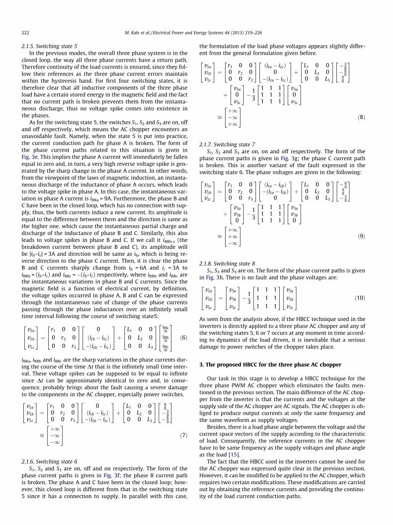
(g) (h)Fig. 3. The phase current path relations in connection with the application of the HBCC to the AC Chopper.
M. Kale et al. / Electrical Power and Energy Systems 44 (2013) 219–226 221
2.1.1. Switching state 1S1, S2 and S3 are off, which the form of the phase current paths is
given in Fig. 3a, then the load phase voltages are equal to zero asthe following:
vLa
vLb
vLc
264
375 ¼
000
264
375� 1
3
1 1 11 1 11 1 1
264
375
000
264
375 ¼
000
264
375 ð2Þ
It is clear that there is no fault.
2.1.2. Switching state 2S1 and S2 are off and S3 is on. The form of the phase current
paths is given in Fig. 3b, which implies no fault.
vLa
vLb
vLc
264
375 ¼
vSa
0vSc
264
375� 1
3
1 1 11 1 11 1 1
264
375
vSa
0vSc
264
375 ð3Þ
2.1.3. Switching state 3S1 and S3 are off and S2 is on. That means there is no fault. The
form of the phase current paths is given in Fig. 3c.
vLa
vLb
vLc
264
375 ¼
vSa
vSb
0
264
375� 1
3
1 1 11 1 11 1 1
264
375
vSa
vSb
0
264
375 ð4Þ
2.1.4. Switching state 4S1 is off and S2 and S3 are on. The form of the phase current
paths is given in Fig. 3d. There is no fault and resulting equationyields:
vLa
vLb
vLc
264
375 ¼
vSa
vSb
vSc
264
375� 1
3
1 1 11 1 11 1 1
264
375
vSa
vSb
vSc
264
375 ð5Þ
222 M. Kale et al. / Electrical Power and Energy Systems 44 (2013) 219–226
2.1.5. Switching state 5In the previous modes, the overall three phase system is in the
closed loop, the way all three phase currents have a return path.Therefore continuity of the load currents is ensured, since they fol-low their references as the three phase current errors maintainwithin the hysteresis band. For first four switching states, it istherefore clear that all inductive components of the three phaseload have a certain stored energy in the magnetic field and the factthat no current path is broken prevents them from the instanta-neous discharge, thus no voltage spike comes into existence inthe phases.
As for the switching state 5, the switches S1, S2 and S3 are on, offand off respectively, which means the AC chopper encounters anunavoidable fault. Namely, when the state 5 is put into practice,the current conduction path for phase A is broken. The form ofthe phase current paths related to this situation is given inFig. 3e. This implies the phase A current will immediately be fallenequal to zero and, in turn, a very high reverse voltage spike is gen-erated by the sharp change in the phase A current. In other words,from the viewpoint of the laws of magnetic induction, an instanta-neous discharge of the inductance of phase A occurs, which leadsto the voltage spike in phase A. In this case, the instantaneous var-iation in phase A current is iBRa = 9A. Furthermore, the phase B andC have been in the closed loop, which has no connection with sup-ply, thus, the both currents induce a new current. Its amplitude isequal to the difference between them and the direction is same asthe higher one, which cause the instantaneous partial charge anddischarge of the inductance of phase B and C. Similarly, this alsoleads to voltage spikes in phase B and C. If we call it iBRb-c (thebreakdown current between phase B and C), its amplitude willbe |ib–ic| = 3A and direction will be same as ib, which is being re-verse direction to the phase C current. Then, it is clear the phaseB and C currents sharply change from ib = 6A and ic = 3A toiBRb = (ib–ic) and iBRc = �(ib–ic) respectively, where iBRb and iBRc arethe instantaneous variations in phase B and C currents. Since themagnetic field is a function of electrical current, by definition,the voltage spikes occurred in phase A, B and C can be expressedthrough the instantaneous rate of change of the phase currentspassing through the phase inductances over an infinitely smalltime interval following the course of switching state5:
vLa
vLb
vLc
264
375 ¼
r1 0 00 r2 00 0 r3
264
375
0ðiLb � iLcÞ�ðiLb � iLcÞ
264
375þ
L1 0 00 L2 00 0 L3
264
375
iBRaDt
iBRbDt
iBRcDt
2664
3775 ð6Þ
iBRa, iBRb and iBRc are the sharp variations in the phase currents dur-ing the course of the time Dt that is the infinitely small time inter-val. These voltage spikes can be supposed to be equal to infinitesince Dt can be approximately identical to zero and, in conse-quence, probably brings about the fault causing a severe damageto the components in the AC chopper, especially power switches.
vLa
vLb
vLc
24
35 ¼ r1 0 0
0 r2 00 0 r3
24
35 0ðiLb � iLcÞ�ðiLb � iLcÞ
24
35þ L1 0 0
0 L2 00 0 L3
24
35
90� 3
0� 6
0
24
35
ffiþ1�1�1
24
35 ð7Þ
2.1.6. Switching state 6S1, S2 and S3 are on, off and on respectively. The form of the
phase current paths is given in Fig. 3f; the phase B current pathis broken. The phase A and C have been in the closed loop; how-ever, this closed loop is different from that in the switching state5 since it has a connection to supply. In parallel with this case,
the formulation of the load phase voltages appears slightly differ-ent from the general formulation given before.
vLa
vLb
vLc
24
35 ¼ r1 0 0
0 r2 00 0 r3
24
35 ðiLa � iLcÞ
0�ðiLa � iLcÞ
24
35þ L1 0 0
0 L2 00 0 L3
24
35 � 3
0� 6
090
24
35
þvSa
0vSc
24
35� 1
3
1 1 11 1 11 1 1
24
35 vSa
0vSc
24
35
ffiþ1�1þ1
24
35 ð8Þ
2.1.7. Switching state 7S1, S2 and S3 are on, on and off respectively. The form of the
phase current paths is given in Fig. 3g; the phase C current pathis broken. This is another variant of the fault expressed in theswitching state 6. The phase voltages are given in the following:
vLa
vLb
vLc
24
35 ¼
r1 0 00 r2 00 0 r3
24
35 ðiLa � iLbÞ�ðiLa � iLbÞ
0
24
35þ
L1 0 00 L2 00 0 L3
24
35 � 6
090� 3
0
24
35
þvSa
vSb
0
24
35� 1
3
1 1 11 1 11 1 1
24
35 vSa
vSb
0
24
35
ffiþ1þ1�1
24
35 ð9Þ
2.1.8. Switching state 8S1, S2 and S3 are on. The form of the phase current paths is given
in Fig. 3h. There is no fault and the phase voltages are:
vLa
vLb
vLc
264
375 ¼
vSa
vSb
vSc
264
375� 1
3
1 1 11 1 11 1 1
264
375
vSa
vSb
vSc
264
375 ð10Þ
As seen from the analysis above, if the HBCC technique used in theinverters is directly applied to a three phase AC chopper and any ofthe switching states 5, 6 or 7 occurs at any moment in time accord-ing to dynamics of the load driven, it is inevitable that a seriousdamage to power switches of the chopper takes place.
3. The proposed HBCC for the three phase AC chopper
Our task in this stage is to develop a HBCC technique for thethree phase PWM AC chopper which eliminates the faults men-tioned in the previous section. The main difference of the AC chop-per from the inverter is that the currents and the voltages at thesupply side of the AC chopper are AC signals. The AC chopper is ob-liged to produce output currents at only the same frequency andthe same waveform as supply voltages.
Besides, there is a load phase angle between the voltage and thecurrent space vectors of the supply according to the characteristicof load. Consequently, the reference currents in the AC chopperhave to be same frequency as the supply voltages and phase angleas the load [15].
The fact that the HBCC used in the inverters cannot be used forthe AC chopper was expressed quite clear in the previous section.However, it can be modified to be applied to the AC chopper, whichrequires two certain modifications. These modifications are carriedout by obtaining the reference currents and providing the continu-ity of the load current conduction paths.
vSa vSb vSc
S1
S1*
SHBA
Fig. 5. Phase A switching signals obtained by minimum voltage algorithm.
Table 2Possible switching states when the phase A voltage is minimum.
M. Kale et al. / Electrical Power and Energy Systems 44 (2013) 219–226 223
3.1. Obtaining the reference currents
The reference currents can be generated in two steps. First, thefrequency and the angle of the space vector of the supply voltagesare obtained via employing the synchronous reference frame PLL.Second, it is required transforming the three phase load currentsinto synchronous reference frame using Park Transformation in or-der to calculate the load phase angle, which is revealed in Eqs. (11)and (12). It follows that d and q axis currents are passed throughfirst order low pass filters (LPF) to obtain the angle of the funda-mental component of the load currents. Then, the phase differencebetween the supply voltages and the load currents can be com-puted as shown in Eq. (13). The load phase angle and the angleof the space vector of the supply voltages are added, which enablesthe three phase reference currents at the same phase as the loadcurrents and the same frequency as the supply voltages to be pro-duced. The maximum value of the reference currents is determinedby the user randomly, which is not in connection with the theory ofthe proposed HBCC.
where I�m is maximum value of the load currents, iLx (x = a, b, c) is theload currents, iLd and iLq are the d and q components of the load cur-rents respectively, ILd and ILq are the filtered d and q components ofiLd and iLq respectively, xt is the angle of the space vector of the sup-ply voltages, u is the load phase angle.
3.2. Producing switching signals and providing the continuity ofcurrent paths
It is possible to ensure the continuity of current conductionpaths through the diodes parallel connected to the IGBTs in theinverters, but this situation is not sufficient for the AC chopper.There are some techniques to guarantee continuity of the currentpaths in the literature for the AC chopper [19,20]. Among them,the algorithm called as ‘turns on the switches of the phase withminimum voltage’ which is proposed in [19] is adapted for theHBCC proposed in this study. It is then ensured that the rightpower switch can be triggered according to the instantaneous val-ues of the supply voltages, which eliminates the faults as guaran-teeing the continuity of the current paths. Otherwise, it isinevitable that the faults mentioned in the previous section occur.
PLL Calculation ofthe Reference
Currents(Equation 11)
dq
abc
vSa
vSb
vSc
iLa
iLb
iLc
iLd
iLq
ϕ
tω ++
Im*
tω
LPF
LPF
Load Angle Calculation
(Equation 13)
ILd
ILq
Fig. 4. Real time implementation s
The measured load currents are subtracted from the referencecurrents as in Eq. (11), with the result that the current errors ofeach phase are acquired. The switching signals (SHBA, SHBB and SHBC)of each phase are formed through applying the HBCC to these cur-rent errors. After the switching signals (SHBA, SHBB and SHBC) arepassed through the ‘Minimum Voltage Algorithm’, they can be ap-plied to the switches in the AC chopper seen in Fig. 4. The outputsignals of the HBCC (SHBA) and the switching signals (S1 and S�1) ob-tained by the ‘Minimum Voltage Algorithm’ are shown in Fig. 5. Astwo switches of the phase having minimum voltage are kept in‘on’, the current control of three phase is implemented by theswitches of the other two phases. Since the current passingthrough the phase having minimum voltage consists of sum ofthe currents of the other two phases, it is indirectly controlled bythe currents of the other two phases that remain within the hyster-esis band. In this way, HBCC of three phase currents can beachieved due to the fact that all the current errors are maintainedwithin the hysteresis band. The two modifications applied to theHBCC used in the inverters are clearly shown in Fig. 4, which alsodepicts the real time implementation scheme of the proposedcontroller.
3.3. Analysis of application of the proposed HBCC to the AC chopper
In order to analyze the proposed HBCC, the following assump-tion is supposed to be valid. The analyses can be expanded all ini-tial conditions and all operating points.
HBController
MinimumVoltage
Algorithm
+ −
−
−+
+
iLa*
iLb*
iLc*
iLa iLb iLc
S1
S2
S3
S1*
S2*
S3*
SHBA
SHBB
SHBC
cheme of the proposed HBCC.
(a) (b)
(c)
S1
S2
S3
vSa
vSb
vSc
S1* S2
* S3*
R L
R L
R L
S1
S2
S3
vSa
vSb
vSc
S1* S2
* S3*
R L
R L
R L
S1
S2
S3
vSa
vSb
vSc
S1* S2
* S3*
R L
R L
R L
(d)
S1
S2
S3
vSa
vSb
vSc
S1* S2
* S3*
R L
R L
R L
Fig. 6. The phase current path relations in connection with the application of the proposed HBCC to the AC Chopper.
Table 3The system parameters used in the simulations.
Parameters Value
Supply Voltage (phase-neutral) VSabc 220 Vrms
Frequency f 50 HzLoad 3-Phase Load Inductances L 20 mH
3-Phase Load Resistors R 10 O
224 M. Kale et al. / Electrical Power and Energy Systems 44 (2013) 219–226
A2 The assumption A1 is valid here as well. For these initial val-ues, the analysis results of the switching’s states given in Table 2can be concluded in the following.
After an infinitely small time following the time t0, we assumedthe switching states given below are put into effect in accordancewith the dynamics of the proposed HBCC.
When the phase A voltage is minimum, all the switching statesgiven in Table 2 are possible to be performed at any moment intime according to the dynamics of the load driven.
3.3.1. Switching state 1S1, S�1, S�2 and S�3 are on, S2 and S3 are off. The form of the phase
current paths is given in Fig. 6a. It follows that:
vLa
vLb
vLc
264
375 ¼
000
264
375� 1
3
1 1 11 1 11 1 1
264
375
000
264
375 ¼
000
264
375 ð14Þ
iLa iLb iLc
Fig. 7. The three phase load curr
3.3.2. Switching state 2S1, S3, S�1 and S�2 are on, S2 and S�3 are off. The form of the phase
currents is given in Fig. 6b. The load phase voltages follow:
vLa
vLb
vLc
264
375 ¼
vSa
0vSc
264
375� 1
3
1 1 11 1 11 1 1
264
375
vSa
0vSc
264
375 ð15Þ
3.3.3. Switching state 3S1, S2, S�1 and S�3 are on, S3 and S�2 are off. The form of the phase
current paths is given in Fig. 6c. The load phase voltages are:
vLa
vLb
vLc
264
375 ¼
vSa
vSb
0
264
375� 1
3
1 1 11 1 11 1 1
264
375
vSa
vSb
0
264
375 ð16Þ
3.3.4. Switching state 4S1, S2, S3 and S�1 are on. The form of the phase current paths is
given in Fig. 6d. In this state, the load phase voltages can be ex-pressed as follow:
vLa
vLb
vLc
264
375 ¼
vSa
vSb
vSc
264
375� 1
3
1 1 11 1 11 1 1
264
375
vSa
vSb
vSc
264
375 ð17Þ
ents in the case of I�m ¼ 20A.
0 5 10 15 20 25 30 35 40 45 500
5
10
15
20
25
Harmonic Order
Cur
rent
s [A
]
Fig. 8. Harmonic spectra of the phase A current.
Im* iLa
Fig. 9. Dynamic responses of the phase A current for step changes in the amplitude of the reference currents.
vSa vSb vSc
iLa iLb iLc
Fig. 10. The load currents under unbalanced supply voltages.
M. Kale et al. / Electrical Power and Energy Systems 44 (2013) 219–226 225
226 M. Kale et al. / Electrical Power and Energy Systems 44 (2013) 219–226
With the proposition of the ‘turn on all the switches of thephase with minimum voltage’, the instantaneous discharge of theinductive components of the load is avoided and thus the continu-ity of three phase load current paths are accordingly ensured,which is verified the analysis results above as well.
4. Simulation results
The simulation results are obtained by the Matlab/Simulink onthe basis of the parameters given in Table 3. In order to examinethe behaviors of the proposed HBCC, the simulations are carriedout for three different cases.
4.1. Case 1
In the case of the reference currents with constant amplitude,20A, and balanced supply voltages, the load currents producedwith the proposed HBCC is shown in Fig. 7. The harmonic spectraof the phase A current is shown in Fig. 8, which reveals the THDis % 2.15. As can be concluded from the Figure, the THD of the cur-rents is quite low and complies with the IEC 1000-3-2 HarmonicStandards.
4.2. Case 2
In the case of the step changes in the amplitude of the referencecurrents (I�m), from 15A to 10A and then to 20A, the dynamic re-sponses of the load currents are plotted in Fig. 9 under balancedsupply voltages. It is clearly concluded from Fig. 9 that the loadcurrents follow the references with high performance andaccuracy.
4.3. Case 3
In the case of the reference currents with constant amplitude,20A, the load currents are given in Fig. 10 under unbalanced supplyvoltages. Since the PLL method used in the proposed HBCC can cor-rectly track the angle of the voltage space vector of the supply evenin the case of unbalanced supply voltages, the reference currentscan be easily generated and thus the load side currents are stablyremained balanced at their reference values. The unbalances inthe supply voltages are chosen as VSa = 220 V, VSb = 240 V andVSc = 205 V.
5. Concluding remarks and discussion
The direct application of the HBCC to three phase PWM ACchopper leads to some serious and unavoidable faults which espe-cially damage to the power switches of the chopper. In order toeliminate these faults, a novel HBCC for the three phase PWM ACchopper is proposed. The contributions obtained in the study canbe given in the following order:
1. The related faults interested in direct application of HBCC tech-nique used in the three phase inverter to the three phase PWMAC chopper are analyzed in detail.
2. Due to the two certain modifications in the HBCC techniqueused in the three phase inverter, the related faults are elimi-nated and the application of the HBCC technique to the threephase PWM AC chopper is achieved.
3. Despite the step changes in the amplitude of the reference cur-rents and unbalanced supply voltages, it is clearly shown theload currents track the reference currents with high perfor-mance and accuracy.
In order to demonstrate validity and performance of the pro-posed method, various operating points being possible to happenin real world applications are taken into consideration in the sim-ulations. As a result, it is obvious a very precise control perfor-mance is achieved. The simulation results prove the validity andfeasibility of the proposed HBCC for the three phase PWM ACchopper.
References
[1] Ahmed NA, Amei K, Sakui M. A new configuration of single-phase symmetricalPWM AC chopper voltage controller. IEEE Trans Ind Electron 1999;46(5):942–52.
[2] Jang DH, Choe GH. Step-up/down AC voltage regulator using transformer withtap changer and PWM AC chopper. IEEE Trans Ind Electron 1998;45(6):905–11.
[3] Mozdzer A, Bose BK. Three-phase AC power control using power transistors.IEEE Trans Ind Appl 1976;IA-12(5):499–505.
[4] Ahmed NA, El Enezi FQ, Al-Othman AK. Comprehensive analysis and transientmodelling of symmetrical single phase PWM AC–AC voltage converters. ElectrPower Syst Res 2011;81:57–65.
[5] Campos A, Joós G, Ziogas PD, Lindsay JF. Analysis and design of a series-connected PWM voltage regulator for single-phase AC sources. IEEE Trans IndAppl 1996;32(6):1285–92.
[6] Nan J, Hou-jun T, Wei L, Peng-sheng Y. Analysis and control of buck-boostchopper type AC voltage regulator. In: IEEE 6th international power electronicsand motion control conference, Wuhan, China; 2009. p. 1019–23.
[7] Kazmierkowski MP, Malesani L. Current control techniques for three-phasevoltage source PWM converters: a survey. IEEE Trans Ind Electron1998;45(5):691–703.
[8] Holtz J. Pulsewidth modulation – a survey. IEEE Trans Ind Electron1992;39(5):410–20.
[9] Rahman MA, Radwan TS, Osheiba AM, Lashine AE. Analysis of current controllersfor voltage-source inverter. IEEE Trans Ind Electron 1997;44(4):477–85.
[10] Rahman KM, Khan MR, Choudhury MA, Rahman MA. Variable-band hysteresiscurrent controllers for PWM voltage-source inverters. IEEE Trans PowerElectron 1997;12(6):964–70.
[11] Buso S, Fasolo S, Malesani L, Mattavelli P. A dead-beat adaptive hysteresiscurrent control. IEEE Trans Ind Appl 2000;36(4):1174–80.
[12] Kale M, Ozdemir E. An adaptive hysteresis band current controller for shuntactive power filter. Electr Power Syst Res 2005;73(2):113–9.
[13] Habeebullah Sait H, Arul Daniel S. New control paradigm for integration ofphotovoltaic energy sources with utility network. Electr Power Energy Syst2011;33(1):86–93.
[14] EL-Kholy EE, EL-Sabbe A, El-Hefnawy A, Mharous Hamdy M. Three-phaseactive power filter based on current controlled voltage source inverter. ElectrPower Energy Syst 2006;28(8):537–47.
[15] Khanniche MS, Lake IDW. Real time hysteresis controller for relay testing. IEEProc Electr Power Appl 1994;141(2):71–6.
[16] Bodur H, Bakan AF, Sarul MH. Universal motor speed control with currentcontrolled PWM AC chopper by using a microcontroller. In: Proceedings ofIEEE international conference on industrial technology, Goa, India; 2000. p.394–98.
[17] Belhaoucheta N, Rahmania L. Development of adaptive hysteresis-bandcurrent control of PWM three-phase AC chopper with constant switchingfrequency. Electr Power Compon Syst 2009;37(6):583–98.
[18] Kilic T, Milun S, Petrovic G. Design and implementation of predictive filteringsystem for current reference generation of active power filter. Electr PowerEnergy Syst 2007;29(2):106–12.
[19] Kwon BH, Min BD, Kim JH. Novel topologies of AC choppers. IEE Proc ElectrPower Appl 1996;143(4):323–30.
[20] Kim JH, Min BD, Kwon BH, Won SC. A PWM buck–boost AC chopper solving thecommutation problem. IEEE Trans Ind Electron 1998;45(5):832–5.