A novel ultra-high speed camera fordigital image processing applicationsA Hijazi1 and V Madhavan2
1 Department of Mechanical Engineering, The Hashemite University, Zarka, Jordan2 Department of Industrial and Manufacturing Engineering, Wichita State University, Wichita, KS, USA
Received 27 March 2008, in final form 22 May 2008Published 30 June 2008Online at stacks.iop.org/MST/19/085503
AbstractMulti-channel gated-intensified cameras are commonly used for capturing images at ultra-highframe rates. The use of image intensifiers reduces the image resolution and increases the errorin applications requiring high-quality images, such as digital image correlation. We report thedevelopment of a new type of non-intensified multi-channel camera system that permitsrecording of image sequences at ultra-high frame rates at the native resolution afforded by theimaging optics and the cameras used. This camera system is based upon the concept of using asequence of short-duration light pulses of different wavelengths for illumination and usingwavelength selective elements in the imaging system to route each particular wavelength oflight to a particular camera. As such, the duration of the light pulses controls the exposure timeand the timing of the light pulses controls the interframe time. A prototype camera systembuilt according to this concept comprises four dual-frame cameras synchronized with fourdual-cavity pulsed lasers producing 5 ns pulses in four different wavelengths. The prototype iscapable of recording four-frame full-resolution image sequences at frame rates up to 200 MHzand eight-frame image sequences at frame rates up to 8 MHz. This system is built around astereo microscope to capture stereoscopic image sequences usable for 3D digital imagecorrelation. The camera system is used for imaging the chip–workpiece interface area duringhigh speed machining, and the images are used to map the strain rate in the primary shear zone.
Keywords: high speed imaging, multi-channel camera, non-intensified camera, multi-colorillumination, digital image correlation, PIV
(Some figures in this article are in colour only in the electronic version)
1. Introduction
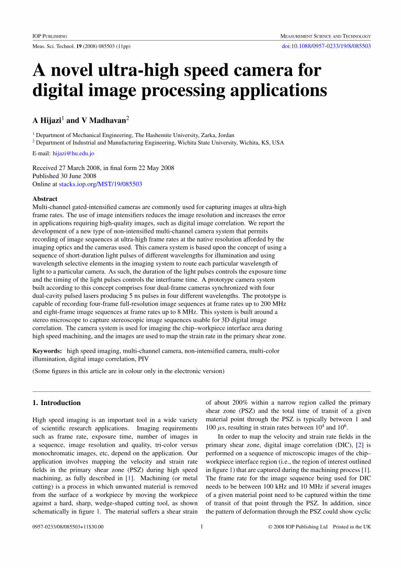
High speed imaging is an important tool in a wide varietyof scientific research applications. Imaging requirementssuch as frame rate, exposure time, number of images ina sequence, image resolution and quality, tri-color versusmonochromatic images, etc, depend on the application. Ourapplication involves mapping the velocity and strain ratefields in the primary shear zone (PSZ) during high speedmachining, as fully described in [1]. Machining (or metalcutting) is a process in which unwanted material is removedfrom the surface of a workpiece by moving the workpieceagainst a hard, sharp, wedge-shaped cutting tool, as shownschematically in figure 1. The material suffers a shear strain
of about 200% within a narrow region called the primaryshear zone (PSZ) and the total time of transit of a givenmaterial point through the PSZ is typically between 1 and100 µs, resulting in strain rates between 104 and 106.
In order to map the velocity and strain rate fields in theprimary shear zone, digital image correlation (DIC), [2] isperformed on a sequence of microscopic images of the chip–workpiece interface region (i.e., the region of interest outlinedin figure 1) that are captured during the machining process [1].The frame rate for the image sequence being used for DICneeds to be between 100 kHz and 10 MHz if several imagesof a given material point need to be captured within the timeof transit of that point through the PSZ. In addition, sincethe pattern of deformation through the PSZ could show cyclic
Meas. Sci. Technol. 19 (2008) 085503 A Hijazi and V Madhavan
Figure 1. Schematic sketch of orthogonal cutting showing theregion of interest.
changes that are of interest, it is desirable to have a capabilityof obtaining a sequence of several images. Considering this,together with a very small field of view, it is apparent that high-resolution microphotographic images need to be captured atframe rates in excess of one million frames per second (fps).High speed cameras capable of frame rates of 1000 000 fps(1 MHz) and above are commonly referred to as ultra-highspeed cameras.
Several onsite demonstrations of multi-channel gatedintensified ultra-high speed cameras were carried out. Thesedemonstrations showed that poor spatial resolution and ratherlarge noise in the intensity values of images obtained bythis type of cameras make the images unsuitable for high-spatial-resolution DIC. The reduced image quality can mainlybe attributed to the use of image intensifiers in this type ofcameras. A need was felt for a new type of non-intensifiedultra-high speed camera capable of recording a sequence ofhigh-resolution images at framing rates exceeding one millionframes per second.
In order to obtain higher quality images, we investigatedthe use of non-intensified cameras coupled with pulsed laserillumination such as those used for particle image velocimetry(PIV) of high speed flows [3]. Dual-phase cameras commonlyused in PIV applications are capable of recording two full-resolution frames on a single CCD in very quick succession(the interframe separation can be as short as 50 ns). This typeof camera is typically referred to as a dual-frame camera. Inthe dual-frame mode of operation [4], the exposure time andinterframe separation are controlled by the timing of the pulsedillumination, typically provided by dual-cavity pulsed lasers.However, dual-frame cameras typically require about 100 msbefore another pair of images can be recorded.
To scale up the frame count, a straightforward approachwould be to construct a multi-channel camera systemcomprising multiple dual-frame cameras that work insynchronization with multiple dual-cavity pulsed lasers.
However, in the dual-frame mode of operation, the exposureduration of the second frame cannot be controlled, i.e., theCCD continues to collect the incident light over the entire timeit takes to complete the read-out of the first frame (which takestens of milliseconds). This means that the second frame of allbut one of the dual-frame cameras will be exposed multipletimes and thus rendered unusable.
In this paper, we present a novel (patent pending) solutionthat has resulted in an ultra-high speed camera system that canacquire image sequences at frame rates exceeding 100 MHzwithout the need for the gating provided by image intensifiers.This is accomplished by using short pulses of illuminationof different wavelengths and wavelength selective opticalelements to prevent the illumination pulse of one wavelength,intended to expose one camera, from exposing multiplecameras. The solution described herein is applicable to avariety of cameras (even film cameras) and pulsed illuminationsources. However, we have chosen to use dual-frame camerascoupled with illumination from dual-cavity pulsed lasersbecause of their many advantages, including the doublingof the frame count. We present a prototype of this typeof camera system comprising four dual-frame cameras andfour dual-cavity pulsed lasers, which is capable of capturinghigh-resolution images at framing rates up to 200 MHz. Theprototype system is built around a stereo microscope such thatit can obtain a sequence of eight images usable for 2D DIC orfour pairs of stereo images usable for 3D DIC [5]. We alsopresent sample results showing the velocity and strain ratefields while machining AISI 1045-HR steel at a cutting speedof 3.3 m s−1.
2. Background
An imaging device consists of an imaging optic (e.g., lens),which collects the light emanating from a target and forms animage of it on a light sensitive medium (photographic film,electronic image sensor, etc) located at the real image plane.High speed imaging is almost as old as imaging itself datingback to the early 19th century [6]. With the very long exposuretimes (several seconds) necessary for capturing images backthen, high speed imaging gave the ability to take still imagesof objects in motion. The significance of high speed imagingstems from the fact that it provides means for observing highspeed phenomena that cannot otherwise be resolved.
2.1. Basics of electronic image sensors
The capabilities of solid-state electronic imaging sensors haverecently experienced rapid development and they have almostentirely replaced the use of photographic films. An electronicimage sensor consists of a matrix of capacitor-like storageelements, known as pixels, formed on an oxide-covered siliconsubstrate. This type of sensor, which is known as the metaloxide semiconductor (MOS) sensor, relies on the photoelectricproperty of silicon to convert the incident light to electricalcharge. As an optical image is projected on the imaging sensor,the photons reaching each pixel generate an electrical charge,usually electrons, the magnitude of which is proportional to
2
Meas. Sci. Technol. 19 (2008) 085503 A Hijazi and V Madhavan
the local intensity of light at that pixel. After the sensor hasbeen exposed to light for a period of time (the integration orexposure time), a pattern of charges is collected in the pixels(i.e., a frame is captured). The pattern of charges is then readout to a storage device, freeing the sensor to capture anotherimage. The two most widely recognized types of MOS sensorsare the complementary metal oxide semiconductor (CMOS)and the charge-coupled device (CCD). Both the CMOS andCCD sensors were invited around the same time, however dueto the more complicated design of CMOS sensors, the CCDtechnology developed much faster and CCD sensors becamemore dominant.
The basic difference between CCD and CMOS sensors isin the way an image (i.e., the pattern of charges collected in thepixels) is transferred out of the sensor after it has been captured.In the most basic type of CCD arrays, known as the ‘fullframe’ CCD [7], once a photogenerated pattern of charges iscollected in the pixels due to exposure to the incident radiation,the incoming light is shuttered. Below the image sectionthere is another row of similar storage elements, which are notphotosensitive (i.e., shielded from light), known as the read-out section. The charges in the pixels are transferred down onerow at a time into the read-out section, which in turn transferscharges along the row then the electric charges are convertedto voltage and transferred out through the output amplifier.Once the analog signal (corresponding to charge level in eachpixel) exits the sensor, it is then digitized and transferred to astorage device. Since the serial transfer of the charges throughthe read-out section takes a relatively long period of time, anexternal shutter (mechanical, magneto-optic or electro-optic)is typically used in order to avoid ‘smear’ of the image (i.e.,the pick up of charges during the transfer period) [7]. Once theentire frame has been read out, the shutter can then be openedto capture the next frame. In a CMOS sensor, on the otherhand, each pixel has its own charge-to-voltage conversion,and in the modern designs, the sensor also includes amplifiers,noise correction and digitization circuits, so the sensor outputsdigital signal. The design of a CMOS sensor allows the signalsto be transferred out of the pixels in parallel, and thus the read-out speed can be much higher than that of a CCD sensor.However, the other functions which are integrated into thepixels increase the design complexity and reduce the areaavailable for light capture, which is known as the ‘fill factor’.Also, with each pixel doing its own conversion, uniformity islower. Each of the two types of sensors has its advantages anddisadvantages. For scientific imaging applications, the mostsignificant advantages of CCDs, as compared to CMOS, arethe higher sensitivity and dynamic range (where both are dueto the higher fill factor) and the lower noise level, whereas themost significant disadvantage is the low read-out speed.
The most commonly used types of CCD arrays are shownschematically in figure 2, the ‘frame-transfer’ CCD, 2(a), andthe ‘interline’ CCD, 2(b) [6, 7]. A frame-transfer CCD isdivided into two identical sections, namely, the image section,which is photosensitive, and the storage section, which isshielded from light. At the end of the time allowed forcharge collection (i.e., the exposure time or the integrationtime), the entire array of charges in the image section is
Figure 2. Common types of CCD arrays: (a) frame-transfer CCD,(b) interline CCD.
quickly transferred (parallel transfer) to the storage sectionin a process known as frame-transfer, whereupon the imagingsection is ready again to acquire one more image. The frameis then read out of the storage section by serial transfer throughthe read-out section. The interline CCD, figure 2(b), worksin a similar manner except that the storage section is in theform of shielded columns spaced between the columns of theimaging pixels. At the end of the exposure time, the chargein each pixel is transferred to the storage pixel adjacent to itand then read out in the usual way. In the interline CCD, thepattern of charges can be transferred to the storage sections ina faster manner as compared to a frame-transfer CCD, due tothe fact that the charge in each pixel is transferred directly toits corresponding storage element. However, the fact that thereare insensitive regions in the image area makes the interlineCCDs less suitable for scientific applications [7].
One of the advantages of frame-transfer and interlineCCD arrays over the basic ‘full frame’ CCD is the minimalsmearing arising from the fact that charges are transferredfrom the imaging pixels much faster using parallel transfer.In many frame-transfer and interline CCD arrays, a framecan be transferred to the storage section in less than amicrosecond. Therefore, for these types of CCDs, the needfor an external shutter (to avoid smearing) is practicallyeliminated. With the elimination of external shuttering,
3
Meas. Sci. Technol. 19 (2008) 085503 A Hijazi and V Madhavan
electronic shuttering can be used instead to control theexposure time. Electronic shuttering is realized by removingthe photogenerated charge within the CCD array duringthe time period preceding the beginning of the exposure(typically achieved by reverse clocking the charges to a drain),allowing charge to accumulate for the required exposuretime, followed by frame-transfer of the image to the storagesection [6].
2.2. High speed imaging
A wide variety of high speed cameras, with framing ratesranging from 1 kHz to 200 MHz, are currently availablecommercially. In common usage, the term ‘high speedcamera’ is used for cameras capable of capturing imagesequences as well as for single shot cameras. A single shothigh speed camera is a camera capable of capturing a highspeed image (i.e., an image with a very short exposure time)that appears to freeze the motion of a moving object. Thespeed of such a camera simply refers to the inverse of theexposure time. On the other hand, high speed cameras beingdiscussed here, which are the most common and practical, arethose capable of capturing a sequence of high speed imageswith very short interframe separation. The speed, or framerate, of such a camera refers to the inverse of the interframetime, while it is naturally understood that, for all practicalpurposes, the exposure time is less than, or at most equal to,the interframe time.
The major limitation on the maximum frame rate thatcan be achieved using CCD image sensors is imposed by thetime needed to read out the captured image(s) from the imagesensor. The read-out speeds of most CCD cameras rangebetween 10 and 40 MHz, with 10 MHz being the most typical.For instance, a 10 MHz read-out speed means that, for a1 megapixel sensor, it would take about 0.1 s to read a fullframe (i.e., the framing rate is 10 Hz). With increasing read-out speeds, the read-out noise also increases, therefore usinghigher read-out speeds is not necessarily desirable.
A variety of techniques can be used to overcome thislimitation on the maximum framing rates imposed by the read-out time. One of these techniques relies on reducing the size ofthe image to be read out (i.e., the pixel resolution) in order toreduce the read-out time and therefore increase the frame rate.Binning, the averaging of neighboring pixels, and windowing,using a subset of the sensor for image capturing and read-out,are two techniques that are used with high resolution CCDsin order to reduce the size of the image and consequentlyincrease the frame rate. Another technique that can be used toachieve much higher framing rates is similar to ‘windowing’,in the sense that a subset of the CCD array is used for eachimage. However, the pixels representing different imagesare interleaved; each set of pixels representing an image isexposed at one particular time, and instead of reading out eachindividual image as it becomes available, the images are kepton the CCD until a number of images are recorded on theCCD and they are all read out together [8, 9]. Furthermore,it is also possible to increase the frame rate by dividing theCCD into multiple regions which are read out simultaneously
Figure 3. Camera exposures and timing of the illumination pulsesfor dual-frame mode of operation. Note that the interframe timecannot be less than the frame-transfer time.
through separate read-out sections [10]. High speed camerasusing a combination of these techniques can acquire imagesequences at frame rates of the order of 1 kHz to 100 kHz.However, these techniques cannot be used to increase theread-out speed by several additional orders of magnitude, aswould be required to achieve truly high speed capture of high-resolution images.
A new type of imaging sensor known as in situ storageimage sensor (ISIS) is capable of recording 100 consecutiveframes with 312 × 260 pixel resolution at a framing rate of1 MHz [11]. The concept of the ISIS CCD is similar to thatof the interline CCD (figure 2(b)) where it has a local memoryinterspersed within the image section, but instead of having asingle storage element for each pixel, multiple elements areavailable. During the image-capturing phase, image signalsare transferred to the in situ memory without being read out ofthe sensor, and the number of obtainable frames in a sequenceis equal to the number of storage elements installed in eachpixel. The storage elements in this type of sensor occupy87% of the total area of each pixel which means that thephotosensitive area of each pixel (i.e., the fill factor) is only13%. Therefore, there are some concerns that such sensor maynot be suitable for applications involving PIV or DIC sincethere is a high chance that two completely different areas offield of view will be captured in any two successive frames.
2.3. High speed dual-frame cameras
The use of short duration illumination pulses permits theoperation of frame-transfer or interline CCDs in a special modeknown as ‘dual-frame’ wherein two images can be recordedin very quick succession [4]. In this mode of operation,the first image is captured at the time the first illuminationpulse is incident on the subject, typically close to the end ofthe exposure time of the first frame, and immediately afterthe frame is transferred to the storage section, the secondillumination pulse is used to expose the subject during theexposure time of the second frame. Figure 3 illustrates thetiming for camera exposure and the illumination pulses in thismode of operation. Note that, though the exposure of thefirst frame can be controlled by the electronic shutteringtechnique described previously, the exposure of the secondframe continues for the entire time it takes for the first imageto be read out from the storage section. However, thoughthe exposure time of the second frame is very long, the
4
Meas. Sci. Technol. 19 (2008) 085503 A Hijazi and V Madhavan
illumination pulse duration defines the ‘effective’ exposuretime. This approach allows the acquisition of a pair of images,one in the image section and the other in the storage section.Thus, in the dual-frame mode of operation the camera cancapture two frames in very quick succession, and then hasto wait for hundreds of milliseconds (the read-out time ofthe two frames) before it can capture another pair of images.The minimum interframe separation is limited by the frame-transfer time, which can be as small as 50 ns for the mostrecent models. Cameras optimized to minimize the frame-transfer time and aimed entirely at this mode of operationare referred to as dual-frame cameras, and a variety of suchcameras are available commercially.
It should be noted that the illumination should be providedin the form of a pulse that ends before frame transfer begins inorder to prevent smearing. Otherwise, smearing during frame-transfer will be significant, since the frame-transfer time is notsmall when compared with the effective exposure time (i.e., theduration of the illumination pulse) and interframe separation.It should also be apparent that this method of image recordingis more suitable for low ambient light conditions since theactual exposure time of the second frame is relatively long.
To realize operation at the minimum interframe timethat these cameras will allow, namely, the frame transfertime, pulsed illumination has to be provided by sources thatare bright enough to adequately expose the CCDs within atime interval that is a small fraction of the frame transfertime, shortly before and shortly after the transfer of the firstframe. Pulsed lasers are increasingly being used as theillumination source where they are capable of providing upto 1 J of illumination within pulse duration as short as afew nanoseconds. If a single laser head is used to producea train of pulses at a very high repetition rate, the energy perpulse will be very small and not sufficient for many imagingapplications. Therefore, when multiple pulses with very shortinter-pulse separation are needed, multiple synchronized laserheads are typically used. Dual-frame cameras are usually usedin conjunction with dual-pulse (dual-cavity) Nd:YAG lasersfor PIV in high speed flows. This type of camera is capableof capturing full-resolution images of good quality; however,the maximum frame rate is limited by the frame-transfer timeand the number of obtainable frames is limited to two.
In order to capture sequences of more than two full-resolutionimages at ultra high speeds, multiple cameras combined intomulti-channel cameras systems are typically used. Multi-channel cameras consist of multiple CCDs or cameras sharingthe same viewing axis (using beam splitter(s), rotating mirror,rotating prism, etc), which are triggered in very quicksuccession to capture a sequence of images [6]. By theuse of multiple cameras, the frame rate limitation imposedby the read-out time is eliminated and multiple images,corresponding to the number of internal cameras or CCDs,can be recorded.
In the most commonly used type of multi-channelcameras, known as a gated intensified camera, the light
collected by the objective lens is delivered to the internalCCDs/cameras using a beam-splitter that splits the image intomultiple identical images (multiple beam-splitters arrangedin a branching configuration can also be used). Each ofthe internal cameras has an image intensifier comprising aphotocathode screen that emits photoelectrons proportionalto the image intensity, a microchannel plate that uses theavalanche effect to amplify the electron current, a scintillatorthat reforms a visible image and a CCD optically coupled tothe scintillator screen to form an electronic image. The abilityto switch the microchannel plate on or off rapidly is usedas an external shutter to control the exposure time (exposuretimes down to about 1.5 ns can be achieved) and the exposuresequence of the CCDs/cameras. The shuttering provided bythe intensifiers removes the requirement that the illuminationbe pulsed. Typically illumination is provided in the form ofa single flash of light of duration long enough to capture asequence of frames. The second function of the intensifier isto amplify the received light (gains up to 103 are commonlyused) which helps reduce the relative importance of read-outnoise. Though frame rates in excess of 100 MHz can beachieved with such cameras, the resolution of the images islimited by the resolution of the intensifiers, which (currently)is 76 line-pairs mm−1 at best. Also, use of image intensifiersreduces image quality due to distortion caused by the couplingoptics, cross-talk between adjacent pixel elements caused bythe microchannel plate and due to the fact that shot noise is alsoamplified by the intensifier. Note that, since image intensifiersare expensive, each of the intensified cameras is usually adual-frame camera such that the frame count is doubled.
There have been also some attempts to devise multi-channel non-intensified high speed cameras [12, 13]. Suchcameras consist of multiple frame-transfer or interlineCCDs/cameras sharing the same viewing axis using a beam-splitter. This type of camera works in synchronization withpulsed illumination sources (typically a laser), where thepulses’ duration and separation define the effective exposuretime and interframe separation for the captured images. Notethat pulsed illumination is necessary or otherwise smearingwill be significant since the frame-transfer time is not smallanymore when compared to the exposure time. Also, it shouldbe noted that the interframe separation between two successiveframes is limited by the frame-transfer time, since no externalshuttering is provided. In addition, there are practicallimitations on the total number of internal CCDs/cameras thatcan be used because the light collected by a single objectivelens needs to be split among several CCDs/cameras. Multi-channel non-intensified cameras working according to thistechnique have been reported to be able to capture four full-resolution consecutive images at frame rate up to 1 MHz [13].
In addition, there are other types of multi-channel non-intensified ultra-high speed cameras such as the rotating mirrorcamera [6] and the Cranz–Schardin camera [14]. In therotating mirror camera, a mirror rotating at a very high speedis used to deliver the incoming light to the internal camerasone at a time. However, images captured using rotating mirrorcameras are not suitable for use in PIV or DIC because theysuffer some loss of resolution due to image drag resulting from
5
Meas. Sci. Technol. 19 (2008) 085503 A Hijazi and V Madhavan
Figure 4. Example cameras and lasers timing for a multi-channelcamera system comprising two dual-frame cameras and twodual-cavity lasers.
the rotation of the mirror. The Cranz–Schardin camera is basedon the principle of using multiple spatially- and temporally-shifted light pulses to capture a sequence of images usingspatially-shifted cameras. The object that is to be imagedis placed between the cameras and the light sources. Anadditional lens is placed between the light sources and thecameras such that it will direct the light coming from anyof the spatially shifted light sources, only, to the cameracorresponding to the spatial location of that light source.However, this type of camera can only be used in verylimited imaging applications where the light passes throughthe imaging scene without significant scattering, such as inshadowgraphy and photoelasticity.
3. Approach
The review presented above, of the capabilities and limitationsof the high speed imaging techniques and technology, showsthat there remains a need for an ultra-high speed imagingsystem capable of capturing a sequence of high-resolutionnon-intensified images, especially for applications involvingDIC or PIV.
A simplistic approach would be to construct a camerasystem consisting of multiple dual-frame cameras, sharingthe same viewing axis using beam-splitter, that work insynchronization with multiple dual-cavity pulsed lasers. Theexposure of the image sensors would be synchronized withmultiple sources of pulsed illumination, where the pulses’duration and separation define the effective exposure timeand interframe separation for the captured images. Figure 4provides an exemplary timing diagram for a system comprisingtwo dual-frame cameras synchronized with two dual-cavitylasers. The exemplary system represented by the figure issupposed to capture a sequence of four consecutive images.However, from the figure it is clear that, since the exposuretime for the second frame of each of the dual-frame camerasis very long (typically about 125 ms), the second frame ofcamera 1 is exposed by three laser pulses (2, 3 and 4), andhence rendered unusable. In general, it can be stated that,for a system comprising n dual-frame cameras, the secondframe of each camera except that synchronized with the lastlaser pulse will be exposed by multiple laser pulses. Thus,one can only obtain n+1 images in a sequence using a systemcomprising n dual-frame cameras (the remaining n−1 imageswill be bleared due to exposure by multiple pulses).
In addition to the limitation on the number of obtainableframes, it should be noted that the minimum interframeseparation cannot be less than the time needed for frame-transfer. Otherwise, even the first image of each camera willbe exposed by multiple laser pulses during the frame-transferprocess and thus the image will be smeared. Referring tofigure 4 for illustration, imagine that the first pulse of laser 2was timed between the first and second pulses of laser 1. Insuch case, the first image of camera 1 will be smeared. Thus,the framing rate of the multi-channel camera cannot exceedthat of a single dual-frame camera. Furthermore, the use ofbeam-splitters that divide the light collected by the front opticsbetween the multiple cameras cuts down the light received byeach of the cameras, necessitating the use of higher powerpulses for illumination.
In multi-channel intensified cameras, the addition of animage intensifier in front of each of the internal camerasprovides means of exposure control and that enables thecamera system to overcome the above-mentioned limitations.In order to be able to overcome these limitations, withoutthe need for image intensifiers, some optical property of theillumination pulses has to be employed in order to preventlight pluses intended to expose one camera from exposingother cameras. A technique has recently been proposed forsimultaneously obtaining velocity fields in two parallel lightsheets in order to obtain the complete velocity gradient tensor[15]. This technique, known as dual-plane PIV, is based onthe use of two light sheets having orthogonal polarizationsalong with polarizing filters in front of the cameras, so thatthe first set of cameras sees the light scattered from the firstlight sheet only and the second set of cameras sees only lightscattered from the second light sheet [16]. The use of differentpolarizations of light permits an alternate method for exposurecontrol, to prevent the light pulses meant to expose one camerafrom also exposing other cameras. If this has been used in thesetup comprising two dual-frame cameras given above as anexample, it would have permitted that system to obtain foursingly exposed frames. However, extending this to additionalnumbers of cameras is infeasible. In addition, there might besome concerns about using light of orthogonal polarizations forilluminating ‘relatively rough’ solid surfaces, such as the casein DIC applications, where the light reflected off the surfacemay have different polarizations causing cross-talk betweenthe images.
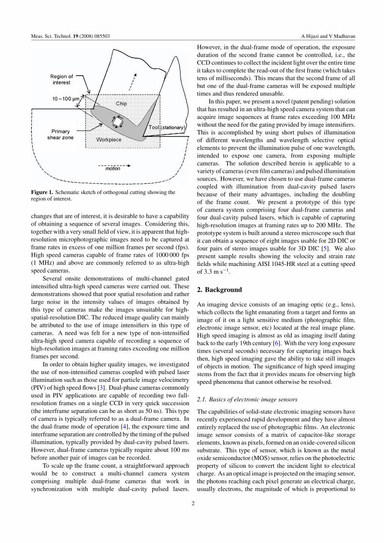
We have devised a similar, but more powerful, solutionthat has resulted in a novel multi-channel ultra-high speedcamera system capable of capturing sequences of full-resolution, high-quality images using multiple non-intensifiedcameras. The essence of the idea is to use multiple light pulsesof different wavelengths for illumination and to use dichroic(i.e., wavelength selective) beam-splitters in the imaging opticsto route light of each wavelength to one particular cameraintended to receive that wavelength. Figure 5 illustrates theconcept of using multiple dichroic beam-splitters to directlight of a particular wavelength to one particular camera.Multiple light pulses of different wavelengths (each pairhaving the same wavelength) are used for illuminating thetarget, and a single objective lens is used to collect the light
6
Meas. Sci. Technol. 19 (2008) 085503 A Hijazi and V Madhavan
Figure 5. Schematic of one possible arrangement of beam-splittersand cameras to illustrate the concept of routing each wavelength oflight to a specific camera, thereby achieving as much control overinterframe time as permitted by the illumination system, rather thanbeing limited by the camera (annotations: BS—beam-splitter,DF—dual-frame).
emanating from the target. Beam-splitters 1 through n−1reflect wavelengths λ1 through λn−1, respectively, therebydirecting light of each wavelength to the appropriate camerawithout unnecessary loss of light intensity. The use of lightpulses of different wavelengths for illumination and dichroicbeam-splitters guarantees that both frames of each camera willbe usable, if dual-frame cameras were used. While figure 5illustrates the concept of using different wavelengths of lightfor control of the exposure where the beam-splitters arearranged in a sequential configuration, other configurations,such as a branching configuration, can also be used.
4. Prototype camera system
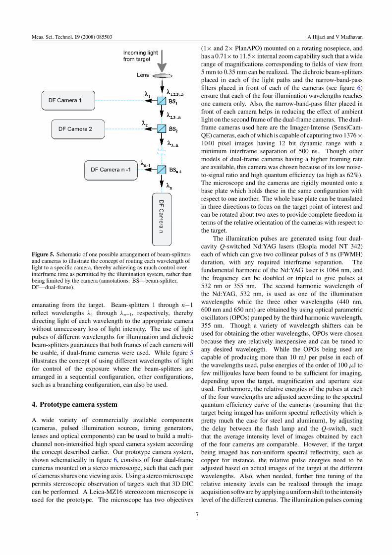
A wide variety of commercially available components(cameras, pulsed illumination sources, timing generators,lenses and optical components) can be used to build a multi-channel non-intensified high speed camera system accordingthe concept described earlier. Our prototype camera system,shown schematically in figure 6, consists of four dual-framecameras mounted on a stereo microscope, such that each pairof cameras shares one viewing axis. Using a stereo microscopepermits stereoscopic observation of targets such that 3D DICcan be performed. A Leica-MZ16 stereozoom microscope isused for the prototype. The microscope has two objectives
(1× and 2× PlanAPO) mounted on a rotating nosepiece, andhas a 0.71× to 11.5× internal zoom capability such that a widerange of magnifications corresponding to fields of view from5 mm to 0.35 mm can be realized. The dichroic beam-splittersplaced in each of the light paths and the narrow-band-passfilters placed in front of each of the cameras (see figure 6)ensure that each of the four illumination wavelengths reachesone camera only. Also, the narrow-band-pass filter placed infront of each camera helps in reducing the effect of ambientlight on the second frame of the dual-frame cameras. The dual-frame cameras used here are the Imager-Intense (SensiCam-QE) cameras, each of which is capable of capturing two 1376 ×1040 pixel images having 12 bit dynamic range with aminimum interframe separation of 500 ns. Though othermodels of dual-frame cameras having a higher framing rateare available, this camera was chosen because of its low noise-to-signal ratio and high quantum efficiency (as high as 62%).The microscope and the cameras are rigidly mounted onto abase plate which holds these in the same configuration withrespect to one another. The whole base plate can be translatedin three directions to focus on the target point of interest andcan be rotated about two axes to provide complete freedom interms of the relative orientation of the cameras with respect tothe target.
The illumination pulses are generated using four dual-cavity Q-switched Nd:YAG lasers (Ekspla model NT 342)each of which can give two collinear pulses of 5 ns (FWMH)duration, with any required interframe separation. Thefundamental harmonic of the Nd:YAG laser is 1064 nm, andthe frequency can be doubled or tripled to give pulses at532 nm or 355 nm. The second harmonic wavelength ofthe Nd:YAG, 532 nm, is used as one of the illuminationwavelengths while the three other wavelengths (440 nm,600 nm and 650 nm) are obtained by using optical parametricoscillators (OPOs) pumped by the third harmonic wavelength,355 nm. Though a variety of wavelength shifters can beused for obtaining the other wavelengths, OPOs were chosenbecause they are relatively inexpensive and can be tuned toany desired wavelength. While the OPOs being used arecapable of producing more than 10 mJ per pulse in each ofthe wavelengths used, pulse energies of the order of 100 µJ tofew millijoules have been found to be sufficient for imaging,depending upon the target, magnification and aperture sizeused. Furthermore, the relative energies of the pulses at eachof the four wavelengths are adjusted according to the spectralquantum efficiency curve of the cameras (assuming that thetarget being imaged has uniform spectral reflectivity which ispretty much the case for steel and aluminum), by adjustingthe delay between the flash lamp and the Q-switch, suchthat the average intensity level of images obtained by eachof the four cameras are comparable. However, if the targetbeing imaged has non-uniform spectral reflectivity, such ascopper for instance, the relative pulse energies need to beadjusted based on actual images of the target at the differentwavelengths. Also, when needed, further fine tuning of therelative intensity levels can be realized through the imageacquisition software by applying a uniform shift to the intensitylevel of the different cameras. The illumination pulses coming
7
Meas. Sci. Technol. 19 (2008) 085503 A Hijazi and V Madhavan
Figure 6. Schematic of the prototype ultra-high speed camera system.
from the four dual-cavity lasers are combined along a singleaxis using high-pass dichroic mirrors. The illumination pulsesare then delivered through a liquid-optic cable to the coaxialilluminator module of the stereo microscope. The liquid-optic cable helps decohere the light reaching the target so thatspeckle patterns are not observed in the images. A picture ofthe prototype camera system being used in our lab is shown infigure 7.
The cameras are controlled through the camera controlcards which communicate with the camera to setup theoperating parameters such as the exposure time and todownload the images. A programmable timing unit (PTU)is used to send the triggering signals to the lasers and thecameras. Twelve channels of the timing generator are used fortriggering the lasers and the cameras, one channel for each ofthe four cameras and one channel for triggering each of theeight laser pulses. Note that for cameras running in the dual-frame mode, only one trigger signal is needed per camera inorder to initiate the first exposure while the timing of the secondframe is controlled by the second illumination pulse. Thoughtwo trigger events are needed to trigger each laser pulse (one forthe flash lamp and one for the Q-switch), however, by using therising and falling edges of the trigger signal to trigger the flashlamp and the Q-switch, respectively, one channel is used fortriggering each laser pulse. The PTU used has a time resolutionof 50 ns and thus can run the camera system at a frame rate
up to 20 MHz. For shorter interframe intervals down to 5 ns(corresponding to a frame rate of 200 MHz), and event basedtriggering, a custom built circuit consisting of photodiodes,digital delay generators and high speed comparators is used.
The DaVis StrainMaster software package is used tocommunicate with and control the cameras, setup the lasertriggers, setup trigger delays to compensate for signalpropagation delays, etc. It is also used for carrying outcalibrations of the imaging system at each of the zoom settingsused and for carrying out 2D and 3D DIC.
5. Discussion
The design concept presented in this paper facilitates thefabrication of a multi-channel ultra-high speed camera capableof a capturing a sequence of high quality images usable in DICor PIV applications. It should be apparent that this conceptis quite general and is applicable to a variety of camera typesand pulsed illumination sources. According to the conceptdescribed here, a system comprising n dual-frame cameras,each of which is limited to a maximum framing rate of f ,can be used to acquire a sequence of 2n frames at a framingrate up to n f , as illustrated for the prototype camera in thetiming diagram in figure 8(a). Specifically, eight frames can
8
Meas. Sci. Technol. 19 (2008) 085503 A Hijazi and V Madhavan
Figure 7. Pictures of the prototype camera system: (a) the fourdual-frame cameras mounted on the stereo microscope, (b) the fourdual-cavity lasers and the beam combining optics.
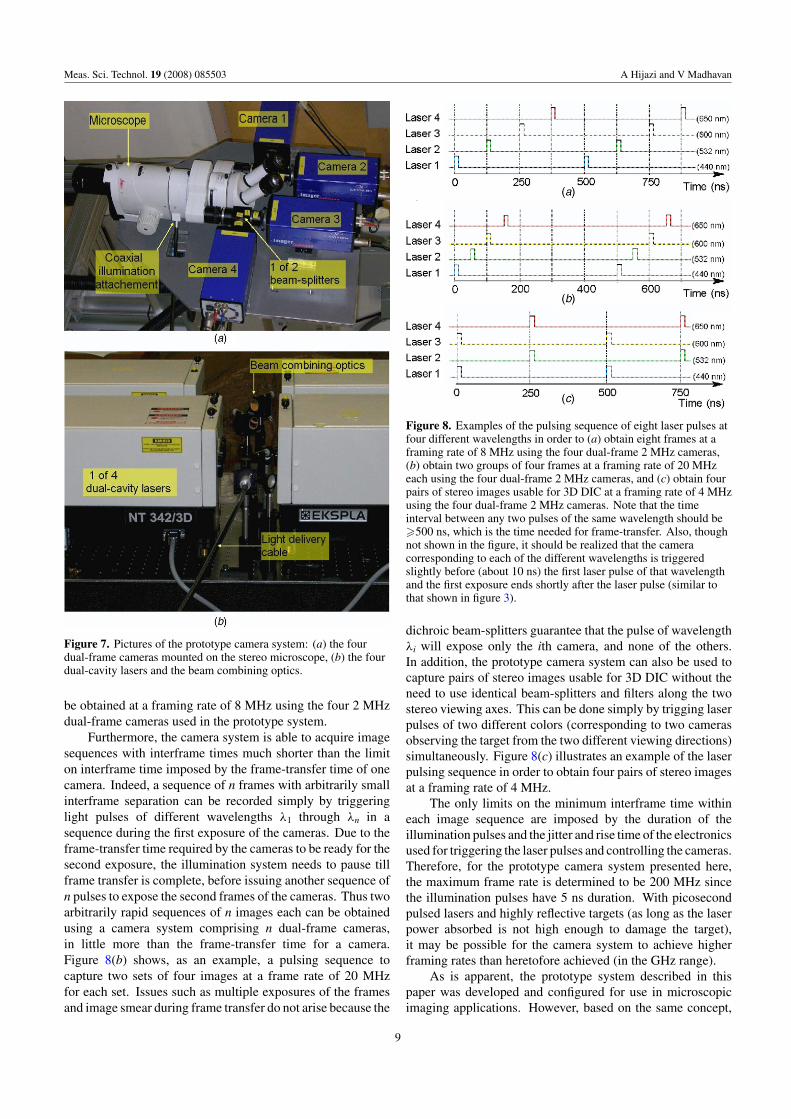
be obtained at a framing rate of 8 MHz using the four 2 MHzdual-frame cameras used in the prototype system.
Furthermore, the camera system is able to acquire imagesequences with interframe times much shorter than the limiton interframe time imposed by the frame-transfer time of onecamera. Indeed, a sequence of n frames with arbitrarily smallinterframe separation can be recorded simply by triggeringlight pulses of different wavelengths λ1 through λn in asequence during the first exposure of the cameras. Due to theframe-transfer time required by the cameras to be ready for thesecond exposure, the illumination system needs to pause tillframe transfer is complete, before issuing another sequence ofn pulses to expose the second frames of the cameras. Thus twoarbitrarily rapid sequences of n images each can be obtainedusing a camera system comprising n dual-frame cameras,in little more than the frame-transfer time for a camera.Figure 8(b) shows, as an example, a pulsing sequence tocapture two sets of four images at a frame rate of 20 MHzfor each set. Issues such as multiple exposures of the framesand image smear during frame transfer do not arise because the
Figure 8. Examples of the pulsing sequence of eight laser pulses atfour different wavelengths in order to (a) obtain eight frames at aframing rate of 8 MHz using the four dual-frame 2 MHz cameras,(b) obtain two groups of four frames at a framing rate of 20 MHzeach using the four dual-frame 2 MHz cameras, and (c) obtain fourpairs of stereo images usable for 3D DIC at a framing rate of 4 MHzusing the four dual-frame 2 MHz cameras. Note that the timeinterval between any two pulses of the same wavelength should be�500 ns, which is the time needed for frame-transfer. Also, thoughnot shown in the figure, it should be realized that the cameracorresponding to each of the different wavelengths is triggeredslightly before (about 10 ns) the first laser pulse of that wavelengthand the first exposure ends shortly after the laser pulse (similar tothat shown in figure 3).
dichroic beam-splitters guarantee that the pulse of wavelengthλi will expose only the ith camera, and none of the others.In addition, the prototype camera system can also be used tocapture pairs of stereo images usable for 3D DIC without theneed to use identical beam-splitters and filters along the twostereo viewing axes. This can be done simply by trigging laserpulses of two different colors (corresponding to two camerasobserving the target from the two different viewing directions)simultaneously. Figure 8(c) illustrates an example of the laserpulsing sequence in order to obtain four pairs of stereo imagesat a framing rate of 4 MHz.
The only limits on the minimum interframe time withineach image sequence are imposed by the duration of theillumination pulses and the jitter and rise time of the electronicsused for triggering the laser pulses and controlling the cameras.Therefore, for the prototype camera system presented here,the maximum frame rate is determined to be 200 MHz sincethe illumination pulses have 5 ns duration. With picosecondpulsed lasers and highly reflective targets (as long as the laserpower absorbed is not high enough to damage the target),it may be possible for the camera system to achieve higherframing rates than heretofore achieved (in the GHz range).
As is apparent, the prototype system described in thispaper was developed and configured for use in microscopicimaging applications. However, based on the same concept,
9
Meas. Sci. Technol. 19 (2008) 085503 A Hijazi and V Madhavan
Figure 9. A sequence of four frames obtained at a frame rate of100 kHz while machining pre-heated steel alloy at 3.3 m s−1. Notethat while this low frame rate is useful for showing the gross motionof the chip, a frame rate of about 1 MHz is needed to perform DICon such images.
similar camera systems can be developed for use in moreconventional types of applications. In fact, such camerasystems have the potential to be used in any type of applicationin which the luminous intensity of the targets, either due to thebackground or due to self-emission, is much less than thatdue to the incident illumination pulses. In addition, if onlythe first frame of each camera is to be used for capturingan image sequence, the low-ambient light requirement of thedual-frame mode of operation may significantly be relaxed.While the level of pulse energy provided by the OPOs beingused in the prototype system (in the order of 10 mJ) might besufficient for some limited PIV applications, such as micro-PIV [17] for instance, however, it should be recognized thatmost of the conventional PIV applications require much higherillumination–pulse energy (at least an order of magnitudehigher than what the OPOs can be provide) due to thefact that only a very small fraction of the illumination isreflected off the seeding particles. In order to provide higherillumination-pulse energy (for conventional PIV applications),pulsed illumination of different wavelengths can be producedby using different lasing mediums, through diode or dye-lasers that fluoresce in different wavelengths, or by usingother types of wavelength shifters such as Raman shifters.For other types of high speed imaging applications, especiallythose that can accommodate pulse durations approaching 1 µs,lower cost illumination options such as the use of xenonflash lamps with filters, laser diodes, etc, can be consideredif the illumination level and exposure duration provided bythose are acceptable. Furthermore, the use of massive banksof relatively inexpensive high power light emitting diodes(LEDs) of different colors might be another feasible option forconstructing a low-cost illumination system; especially sinceit has been demonstrated to be feasible in the Cranz–Schardinconfiguration [14] and since it has been shown [18] that pulsesdown to 1 ns duration can be generated using LEDs.
(a) (b)
(c) (d )
(e) (f )
Figure 10. Process by which the velocity field and strain rate areobtained for AISI 1045 HR at a cutting speed of 3.3 m s−1 with a 5◦
rake tool. (a) and (b) stereoscopic pairs (left and right) of imagestaken at t = 0; (c) and (d) stereo pairs at t = 1 µs; (e) velocityvectors between t = 0 and t = 1 µs; and ( f ) fringes of shear strainrate (annotations: W—workpiece, S—shear zone, C—chip).
6. Sample results
The ultra-high speed camera system is being used for obtainingmicroscopic images of the chip–workpiece interface region(see figure 1) during high speed machining [1]. Figure 9shows a sequence of four images acquired at a frame rateof 100 kHz while cutting pre-heated steel alloy at a cuttingspeed of 3.3 m s−1. A typical sequence of images captured bythe prototype camera system at such frame rate will compriseeight consecutive frames, however due to the similarity of theimages only four frames are shown. This sequence of imageswas captured at a relatively low magnification (the field ofview is approximately 3.5 mm × 2.5 mm), and is shown forillustrative purposes where one can observe the overall natureof the chip formation process. For a cutting speed of 3.3 m s−1
and a feed of 150 µm per revolution, images need to becaptured at a magnification of 23× and a frame rate of about1 MHz in order to map the deformation accurately, due to thehigh strain-rate deformation that takes place in the shear zone.
Figure 10 shows a typical set of two stereo pairs obtainedusing two of the cameras (each pair is captured simultaneouslyby two cameras) with an interframe separation of 1 µs betweenthe two sets of stereo pairs (a–b and c–d ) while cuttingAISI 1045HR at 3.3 m s−1. The images are captured atthe maximum magnification level where the field of view inthese pictures is approximately 350 µm × 250 µm, with eachpixel covering a 0.27 µm × 0.27 µm area. For 3D DIC,
10
Meas. Sci. Technol. 19 (2008) 085503 A Hijazi and V Madhavan
each pair of images obtained simultaneously from the left andright perspectives (a and b for instance) is correlated to locatethe same features in both the views. By the application oftriangulation to the positions of corresponding points in theimages in the two views, the topography of the surface at thetime of observation is obtained. By cross correlating images attwo times, and using the topographical information determinedby triangulation, the three components of displacement at eachpoint on the surface are obtained, as shown in figure 10(e). Thevelocity field can be obtained by dividing the displacement bythe time interval, provided the time interval is sufficiently shortto obtain an instantaneous spatial velocity field rather than atime averaged material rate. The gradient of the velocity fieldyields the strain rate field, from which the equivalent strain ratecan be obtained, see for instance, figure 10( f ). By correlatingthe images obtained while translating the workpiece withoutcutting it, it is found that images can be processed to result ina strain data point every eight pixels (a spatial resolution of2 µm) with a strain noise less than 0.1% strain [1].
7. Concluding remarks
A novel multi-channel non-intensified ultra-high speed camerasystem comprising multiple dual-frame cameras and pulsedillumination sources is presented. The camera system is basedon the idea of using light pulses of different wavelengths androuting light of a particular wavelength to only a particularcamera using dichroic beam-splitters so that the exposuretiming can be controlled by the timing of the light pulses.The concept is quite general and is applicable to a varietyof cameras and pulsed illumination sources. This conceptallows the interframe separation to be infinitesimally small andresults in a camera system where non-intensified cameras canbe combined together to capture a sequence of high-resolutionimages at ultra-high speed. A prototype of the camera systemwas built around a stereo microscope and consists of four dual-frame cameras and four dual-cavity lasers. The prototypecamera system is capable of capturing a sequence of high-resolution images usable for 2D or 3D DIC at framing ratesup to 200 MHz. The camera system is being used withgood success to capture high-resolution microscopic imagesof the PSZ during high speed machining, which yield strainmeasurements at spatial resolutions down to 2 µm with noiseless than 0.1%.
Acknowledgments
We are pleased to acknowledge the financial support bythe National Science Foundation (Grant numbers: DMI-0116675 and DMI-0421394, Program Manager: GeorgeHazelrigg). The prototype camera system is available inthe Manufacturing Processes Research Lab at Wichita StateUniversity (http://engr.wichita.edu/vmadhavan/MPRL.htm).
References
[1] Madhavan V, Mahadevan D, Sheshadri A, Yegneswaran K,Adibi-Sedeh A, Hijazi A and Saket-Kashani M 2008Experimental determination of velocity and strain rate fieldsin metal cutting J. Mech. Phys. Solids at press
[2] Sutton M, Wolters W, Peters W, Ranson W and McNeill S1983 Determination of displacements using animproved digital correlation method Image Vis. Comput.1 133–9
[3] Willert C, Raffel M, Kompenhans J, Stasicki B and Kahler C1996 Recent applications of particle image velocimetry inaerodynamic research Flow Meas. Instrum. 7 247–56
[4] Lecordier B, Mouqallid M, Vottier S, Rouland E, Allano D andTrinite M 1994 CCD recording method for cross-correlationPIV development in unstationary high-speed flows Exp.Fluids 17 205–8
[5] Luo P, Chao Y, Sutton M and Peters W 1993 Accuratemeasurement of three-dimensional deformations indeformable and rigid bodies using computer visionExp. Mech. 33 123–32
[6] Ray S 1997 High Speed Photography and Photonics(Bellingham, WA: SPIE Press)
[7] Burt D 1995 Extending the performance limits of CCD imagesensors GEC J. Res. 12 130–40
[8] Nebolsine P, Snyder D and Grace J 2001 MHz classrepetitively Q-switched high-power ruby lasers forhigh-speed photographic applications Proc. AIAA2001-0845
[9] Lowrance J, Mastrocola V, Renda G, Swain P, Kabra R,Bhaskaran M, Tower J and Levine P 2004 Ultra-high frameCCD imagers Proc. SPIE 5210 67–75
[10] Smith G, Phillips P, Middleton M and Archibald A 1994High-speed CCD read-out camera system Proc. SPIE2273 61–70
[11] Etoh G et al 2003 An image sensor which captures 100consecutive frames at 1000 000 frames/s IEEE Trans.Electron Devices 50 144–51
[12] Willert C, Stasicki B, Raffel M and Kompenhans J 1995Digital video camera for application of particle imagevelocimetry in high-speed flows Proc. SPIE 2546124–34
[13] Gray C, Skopp D, Wieneke B and Reckers W 2001High-speed PIV using high-frequency diode-pumped solidstate laser and multi-frame CCD Proc. Int. Cong. onInstrumentation in Aerospace Simulation Facilitiesp 135
[14] Bretthauer B, Meier G and Stasicki B 1991 An electronicCranz–Schardin camera Rev. Sci. Instrum. 62 364–8
[15] Kaehler C and Kompenhans J 1999 Multiple plane stereoPIV—technical realization and fluid-mechanicalsignificance Proc. Int. Workshop on PIV p 281
[16] Hu H, Saga T, Kobayashi T, Taniguchi N and Yasuki M 2001Dual-plane stereoscopic particle image velocimetry: systemset-up and its application on a lobed jet mixing flow Exp.Fluids 31 277–93
[17] Shinohara K, Sugii Y, Aota A, Hibara A, Tokeshi M,Kitamori T and Okamoto K 2004 High-speed micro-PIVmeasurements of transient flow in microfluidic devicesMeas. Sci. Technol. 15 1965–70
[18] Veledar O, Byrne P, Danaher S, Allen J, Thompson L andMcMillan J 2007 Simple techniques for generatingnanosecond blue light pulses from light emitting diodesMeas. Sci. Technol. 18 131–7


![A NOVEL ULTRA WIDE BAND YAGI MICROSTRIP ANTENNA · PDF fileA NOVEL ULTRA WIDE BAND YAGI MICROSTRIP ANTENNA FOR WIRELESS APPLICATIONS ... [14] HFSS: High frequency structure simulator](https://static.documents.pub/doc/80x56/5a7034b87f8b9abb538bb8bd/a-novel-ultra-wide-band-yagi-microstrip-antenna-wwwjatitorgvolumesresearch-papersvol22no14vol22no1pdfpdf.jpg)


