Abstract A numerical approach for the stress analysis concerning the application of the local fatigue approach to representative details from two Portuguese railway bridge details is presented in this paper. Two types of joints are modelled using the finite element method – riveted and welded joints. The first case study consists on a riveted connection from the Trezói Bridge. The boundary conditions applied to the local finite element model of the joint are provided by a global beam finite element model of the bridge. Damage analysis is performed using the Basquin relation. The other case study is the Alcácer do Sal bridge. Three representative welded details are modelled and used to perform a fatigue damage analysis taking into account distinct dynamic train models. For these models, a submodelling process was used to provide the necessary boundary conditions representing several train crossings. Structural stresses are evaluated at welds using a stress-linearization procedure across the thickness. Keywords: fatigue analysis; local approaches; welded joints; riveted joints; numerical analysis; finite element method; submodelling process.
1 Introduction In Europe and North America there are a number of old riveted highway and railway bridges, constructed during the second half of the 19th century up to the middle of the 20th century which, due to economic reasons, are still in operation. Since they have been subjected to increasing traffic intensity along their operational lives, both in terms of vehicle gross weights/axle loads as well as truck/train frequencies, their damage levels need to be assessed in order to decide about possible repairs. Thus, the maintenance and safety of these existing bridges is a major concern of governmental agencies.
Paper 115 A Numerical Approach for Local Fatigue Analysis of Bridge Details: Analysis of Two Portuguese Case Studies A.L.L. Silva1, A.M.P. Jesus2 and A.A. Fernandes1 1 Faculty of Engineering, Porto University, Portugal 2 University of Trás-os-Montes e Alto Douro, Portugal
In order to assure high safety levels in old riveted steel bridges, highway and railway authorities have to invest heavily in their maintenance and retrofitting. In particular, fatigue failures are a concern for riveted steel bridges since they were not originally designed taking into account fatigue. The fatigue phenomenon was only intensively investigated after the half of the 20th century, when the riveted construction was no longer applied in new bridge structures. Therefore, there is a lack of a comprehensive methodology for the fatigue assessment of riveted bridges motivated by limited knowledge on the fatigue behaviour of this type of construction as well as a deficient understanding on the fatigue behaviour of the old materials (wrought-iron, puddle iron or old steels).
A number of fatigue assessment methodologies for riveted railway bridges have been proposed in the past [1-2], some being of probabilistic form [3-5]. The proposed probabilistic approaches seek the probability of failure or the reliability index, being inherent the comparison of the probabilistic fatigue strength data with the probabilistic fatigue loading. Some of the proposed methodologies for fatigue assessment of riveted bridges aimed the estimation of the remaining life of the primary members of the bridge (main girders, stringers, cross-girders [1-5] and are supported by simplified global models of the bridge. However, most of the fatigue-damage related cases that have been reported for the riveted bridges were observed on riveted connections between the primary members and the fatigue damage has been attributed to secondary effects (e.g. out of plane deformation[6-7]. Very few fatigue assessments of riveted connections have been based on a detailed stress analysis such as that provided by finite element models [8-10].
Despite the S-N approach is widely used to assess the fatigue damage for riveted steel constructions [1-2, 11], Fracture Mechanics [12-13] appears as an alternative approach to perform residual life calculations. However, the use of the Fracture Mechanics is very often limited to the application of simplified formulae for stress intensity factors evaluation, available in standard handbooks [14]. For example, the stress intensity factor in a cracked plate is calculated by considering an isolated plate rather than a plate integrated in a riveted structural member. No interaction is taken into account between the cracked plate and the remaining components of the member. This may result in inconsistent residual life evaluations (ex. residual life overestimation), motivating the search for more accurate stress intensity factors evaluation.
Very few works can be found in literature [15] regarding the stress intensity evaluation for riveted built-up beams. Riveted built-up beams are typical from the end of 19th /beginning of 20th centuries, when technology did not offer manufactured hot rolled beams or welding techniques for making welded connections. Moreno & Valiente [15] proposed an analytical model to assess the stress intensity factors for cracked web of a riveted T beam. The proposed model neglects friction effects and the clamping stresses on rivets and is limited to the specific investigated geometry. In a few number of cases, detailed 3D finite element models have been used in stress analysis of uncracked riveted connections [8-10, 16-18]. The analysis of cracked riveted geometries, using 3D finite element models is almost inexistent. Authors of the paper presented recently such approach for fatigue assessment of a single riveted joint [19].
3
Modern construction of railway bridges is very often based on composite construction technology, where welded joints are typically used to join the steel components. The fatigue behaviour of welded structures is a hot topic of research, with important advances in the last decades. Several techniques for fatigue assessment of welded joints have been proposed in the current literature, such as using structural stress or strain concepts, notch stress or strain concepts and also using Fracture Mechanics concepts. The notch stress and strain methods are based on local stresses and strains. The elastic notch stress has been proposed for high cycle fatigue, while the elastoplastic notch strain method is proposed for low-medium cycle fatigue. These local methods take into account the local geometry of the notches, which constitutes a challenge due to its variability. The IIW recommendations propose a fictitious weld toe radius to solve this problem [20]. Fracture Mechanics approach is mostly associated to crack propagation concepts as well as to notch stress intensity factor concepts. The first concept requires the definition of an initial crack, which could be an actual or assumed short crack. The structural stress concepts have been proposed to account for stresses at crack initiation sites (hot spots) due to geometrical inhomogeneities, but ignoring notch effects introduced by the weld itself. Surface extrapolation procedures are a usual approach to compute the structural stresses (or hot spot stresses) based upon stress measured or calculated at reference locations, adjacent to the local notch. To avoid the nonlinear effects of the weld geometry, these reference locations are located outside the region affected by the notch singularity of the weld toe. The distance from the weld toe is usually parameterized using the plate thickness, t. The International Institute of Welding (IIW) proposes a minimum distance from the weld toe of 0.4t [21]. Different surface extrapolation techniques have been proposed by several other organizations, differing only in the location of their reference locations. However, these techniques are mesh sensitive, leading to different structural stresses, for the same notch, when distinct mesh parameters are adopted. To avoid mesh sensitive results [20, 22-25)], some authors [26-29] have proposed alternative methods, namely through thickness methods. In the through thickness methods, the structural stress is based upon the stress distribution across the plate thickness, at the weld toe. The American Society of Mechanical Engineers (ASME) guidelines, for the design of pressure vessels, suggest a hot spot stress definition based upon through the thickness approach suggested by Radaj [26,27]. A revision of these guidelines was recently undertaken to include improvements suggested by Dong [28]. Another through thickness definition of hot spot stress has been recently proposed by Xiao and Yamada [29]. This procedure has been applied and validated to distinct welded attachment geometries. This paper proposes finite element numerical procedures for the detailed/local stress analysis of joints from types of railway bridges, namely a 50 years old riveted bridge and a recently inaugurated composite/welded bridge. The numerical models are used to compute the local stress histories taking into account the dynamic effects of the train crossings, which may be used in fatigue damage analysis using local S-N approaches.
4
2 Trezói railway bridge The Trezói bridge (Figure 1 a)) is located in the Portuguese Beira Alta railway line, 62 km north of Mortágua, in the village of Trezói. This bridge was opened to traffic on August, 20th , 1956, with a single track. The bridge is a riveted metallic bridge with three spans of 39 m, 48 m and 39 m, totalizing 126 m in length. The two inverted Warren truss girders that constitute the metallic deck of the bridge deck are 5.68 m height. The girders panels are 6.50 m wide in the central span and 6.00 m in the end spans. Two trapezoidal shape trusses acting as piers and two granite masonry abutments transmit the loads carried by the structure to the foundation. The bridge has a constant width of 4.40m, throughout its length. The structural node 6, as illustrated in Figure 1 b), was selected as a potential fatigue critical node, based on preliminary global analysis of the structure, using global beam finite element models. This node is located just over the pier of the bridge and connects a cross girder to the upper stringer, side diagonals and the post. Also, some bracing members are connected to the node, as illustrated by Figure 1 b).
Figure 1: Riveted railway Trezói bridge: a) overview of the bridge; b) node under investigation.
3 Alcácer do Sal railway bridge The new Alcácer do Sal bridge (Figure 2) is a composite bowstring railway bridge, located in the Portuguese railway line that links Lisbon to Algarve. The bridge has 3 spans of 160 m each totalizing a length of 480 m. The bridge is part of a longer structure composed by the North access viaduct (with a length of 1115 m) and the South access viaduct (with a length of 1140 m). The bridge’s deck is suspended axially by 18 vertical hangers per arch, with the hangers being placed 8 m apart from each other’s. The cross section of the deck is a composite box-girder, with 15.85 m width and about 3 m height. The steel box has a total height of 2.6 m and the concrete slab has a total thickness of 0.40 m to 0.20 m. A diaphragm is present at each deck to hanger connection section, with the corresponding 18 diaphragms per span. Transversal stiffeners are placed at the bottom flange, half-way between diaphragms. The bridge’s arch has a tapered hexagonal hollow section.
a) b)
5
Figure 2: Composite bowstring railway Álcacer do Sál bridge. In the definition of the critical details for vibration induced fatigue, two aspects were considered the most relevant. The first one was the classification of the details. A careful analysis of a series of details, revealed the ends of the diagonals as the details with lower fatigue strength classification. Welded joints are potential fatigue critical details which have to be assessed in detail, through a local modeling. Local modeling is required to assess the local (e.g. structural) stresses and to look for potential fatigue cracking hot spots. The inside of the box girder is illustrated in Figure 3 a), where are pointed out the detail that was considered to modeled. The efforts were concentrated in two diaphragms (diaphragms 51 and 54), as pointed out in Figure 3b). The section is reinforced with welded ribs all around the section forming a diaphragm.
Detail A
Detail C
Detail B
Investigated Diaphragm
Figure 3: Box girder of the Alcácer do Sal bridge with investigated local details (a) and locations of the investigated diaphragms (b).
4 Finite element model of a structural detail of the Trezói
bridge The structural node 6 illustrated in Figure 1 b) was selected as a potential fatigue critical node, based on preliminary global analysis of the structure using beam finite
a) b)
6
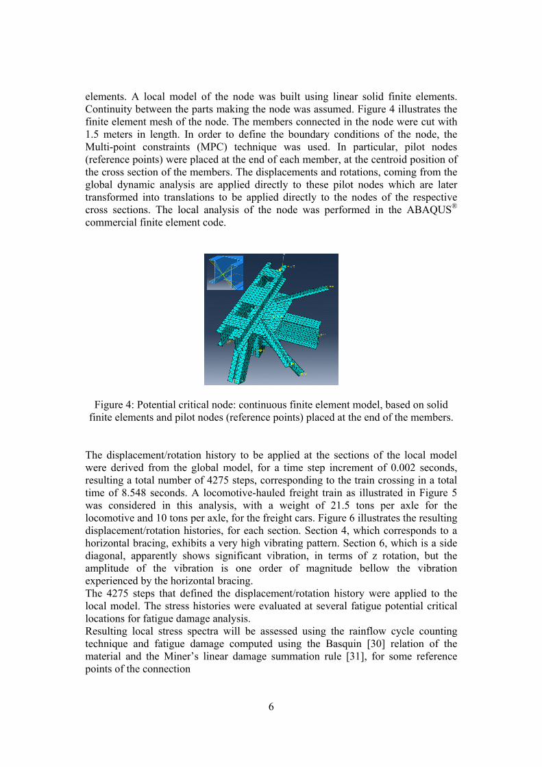
elements. A local model of the node was built using linear solid finite elements. Continuity between the parts making the node was assumed. Figure 4 illustrates the finite element mesh of the node. The members connected in the node were cut with 1.5 meters in length. In order to define the boundary conditions of the node, the Multi-point constraints (MPC) technique was used. In particular, pilot nodes (reference points) were placed at the end of each member, at the centroid position of the cross section of the members. The displacements and rotations, coming from the global dynamic analysis are applied directly to these pilot nodes which are later transformed into translations to be applied directly to the nodes of the respective cross sections. The local analysis of the node was performed in the ABAQUS® commercial finite element code.
Figure 4: Potential critical node: continuous finite element model, based on solid finite elements and pilot nodes (reference points) placed at the end of the members.
The displacement/rotation history to be applied at the sections of the local model were derived from the global model, for a time step increment of 0.002 seconds, resulting a total number of 4275 steps, corresponding to the train crossing in a total time of 8.548 seconds. A locomotive-hauled freight train as illustrated in Figure 5 was considered in this analysis, with a weight of 21.5 tons per axle for the locomotive and 10 tons per axle, for the freight cars. Figure 6 illustrates the resulting displacement/rotation histories, for each section. Section 4, which corresponds to a horizontal bracing, exhibits a very high vibrating pattern. Section 6, which is a side diagonal, apparently shows significant vibration, in terms of z rotation, but the amplitude of the vibration is one order of magnitude bellow the vibration experienced by the horizontal bracing. The 4275 steps that defined the displacement/rotation history were applied to the local model. The stress histories were evaluated at several fatigue potential critical locations for fatigue damage analysis. Resulting local stress spectra will be assessed using the rainflow cycle counting technique and fatigue damage computed using the Basquin [30] relation of the material and the Miner’s linear damage summation rule [31], for some reference points of the connection
7
Figure 5: Locomotive-hauled freight train.
Figure 6: Displacement/rotations histories for sections 1 to 9 of node 6, from Trezói
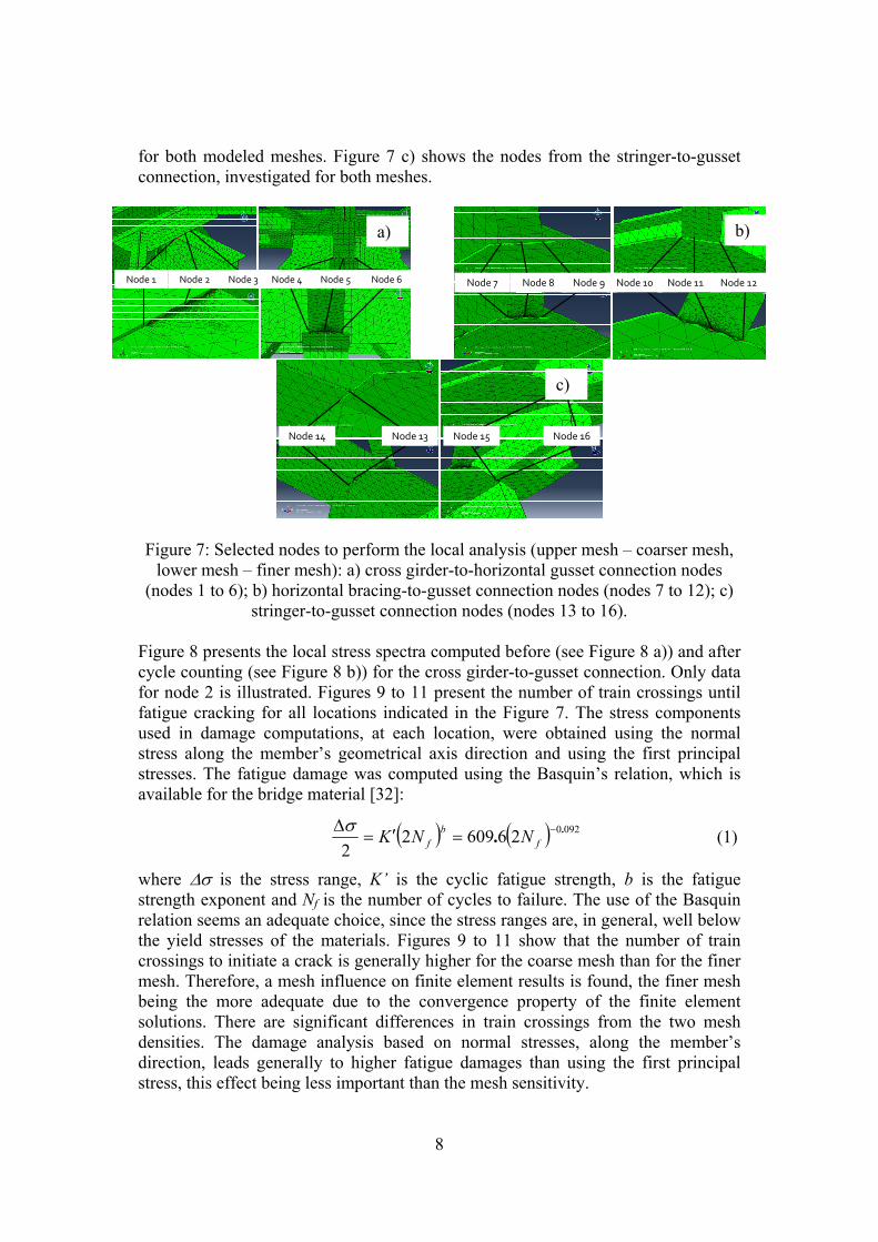
bridge. In order to account for the mesh size effect, two meshes were modeled, namely a coarse mesh (mesh 1) and finer mesh (mesh 2). The finer mesh shows globally the same mesh density as that of the coarse mesh, with the exception of the locations to be assessed, which were further refined. Figure 7 presents the location of the nodes as well as the meshes used in this study. In particular, Figure 7 a) shows the nodes selected from the cross girder-to-horizontal gusset connection, for both meshes. Figure 7 b) shows the nodes of the horizontal bracing-to-gusset connection studied,
8
for both modeled meshes. Figure 7 c) shows the nodes from the stringer-to-gusset connection, investigated for both meshes.
nó 1 nó 2 nó 3 nó 4 nó 5 nó 6 Node 1 Node 2 Node 3 Node 4 Node 5 Node 6 nó 7 nó 8 nó 9 nó 10 nó 10 nó 11 Node 7 Node 8 Node 9 Node 10 Node 11 Node 12
nó 13 nó 14 nó 15nó 12Node 14 Node 13 Node 15 Node 16
Figure 7: Selected nodes to perform the local analysis (upper mesh – coarser mesh,
lower mesh – finer mesh): a) cross girder-to-horizontal gusset connection nodes (nodes 1 to 6); b) horizontal bracing-to-gusset connection nodes (nodes 7 to 12); c)
stringer-to-gusset connection nodes (nodes 13 to 16). Figure 8 presents the local stress spectra computed before (see Figure 8 a)) and after cycle counting (see Figure 8 b)) for the cross girder-to-gusset connection. Only data for node 2 is illustrated. Figures 9 to 11 present the number of train crossings until fatigue cracking for all locations indicated in the Figure 7. The stress components used in damage computations, at each location, were obtained using the normal stress along the member’s geometrical axis direction and using the first principal stresses. The fatigue damage was computed using the Basquin’s relation, which is available for the bridge material [32]:
( ) ( ) 09202660922
.. −=′=Δ
fb
f NNKσ (1)
where Δσ is the stress range, K’ is the cyclic fatigue strength, b is the fatigue strength exponent and Nf is the number of cycles to failure. The use of the Basquin relation seems an adequate choice, since the stress ranges are, in general, well below the yield stresses of the materials. Figures 9 to 11 show that the number of train crossings to initiate a crack is generally higher for the coarse mesh than for the finer mesh. Therefore, a mesh influence on finite element results is found, the finer mesh being the more adequate due to the convergence property of the finite element solutions. There are significant differences in train crossings from the two mesh densities. The damage analysis based on normal stresses, along the member’s direction, leads generally to higher fatigue damages than using the first principal stress, this effect being less important than the mesh sensitivity.
a) b)
c)
9
0
10
20
30
40
50
60
0 1000 2000 3000 4000
σ[M
Pa]
Steps
Série4
Série3
Série2
Série1
Δσn - FE mesh 2
Δσn - FE mesh 1
Δσ1 - FE mesh 1
Δσ1 - FE mesh 2
0
10
20
30
40
50
60
0 50 100 150 200 250 300
6
[MPa]
Number of cycles
Sn - malha EF 1
S1 - malha de EF 1
Sn
S1
6 n - FE mesh 2
6 n - FE mesh 1
6 1 - FE mesh 1
6 1 - FE mesh 2
Figure 8: Illustration of local stress analysis at one location (node 2, Figure 7 a)): local stress evolution computed through the normal local stress and the first
principal stress, before cycle counting; b) local stress evolution computed through the normal local stress and the first principal stress, after cycle counting.
Figure 9: Number of train crossings required to initiate a crack computed using the stress evolution in the cross girder-to-horizontal gusset connection nodes (node 1, 2, 3, 4, 5 and 6): a) computed using the normal local stress; b) computed using the first
Figure 10: Number of train crossings required to initiate a crack computed using the stress evolution in the horizontal bracing-to-gusset connection nodes (node 7, 8, 9, 10, 11 and 12): a) computed using the normal local stress; b) computed using the
first principal stress.
a) b)
a) b)
a) b)
10
FE mesh 1
FE mesh 21.00E+00
1.00E+02
1.00E+04
1.00E+06
1.00E+08
1.00E+10
1.00E+12
1.00E+14
1314
1516
Num
ber o
f tra
in c
ross
es u
ntil
crac
king
( D=
1)
Nodes
FE mesh 1
FE mesh 21.00E+00
1.00E+02
1.00E+04
1.00E+06
1.00E+08
1.00E+10
1.00E+12
1.00E+14
1314
1516
Num
ber o
f tra
in c
ross
es u
ntil
crac
king
( D=
1)
Nodes
Figure 11: Number of train crossings required to initiate a crack computed using the stress evolution in the stringer-to-gusset connection nodes (node 13, 14, 15 and 16):
a) computed using the normal local stress; b) computed using the first principal stress.
In general, the fatigue damage values are low for the investigated locations, leading to a significant number of train crossings. Nevertheless, the lower number of strain crossings to initiate a crack was about 4.45×10⁵ and was obtained for the stringer-to-gusset connection. The horizontal bracing-to-gusset connection and the stringer-to-gusset connection have revealed to be more critical. These conclusions may be influenced by the fact that full continuity was assumed between the plates and members which, in reality, are joined by rivets. Models with rivets and using contact elements may reveal other critical locations, namely at riveted joints. Despite the horizontal bracing-to-gusset connection and the stringer-to-gusset connection have revealed to be more critical, inspections to the bridge did not revealed fatigue crack at that locations.
5 Finite element modelling of welded joints of the Alcácer
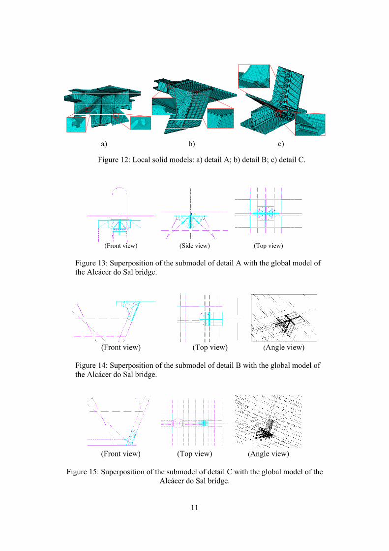
do Sal Bridge As referred in the Section 3, three welded details of the Alcácer do Sal Bridge were subjected to local modeling. The complexity of these details is very high, namely concerning the weld geometry modeling. In situ measurements of weld profiles were carried out to verify the main dimensions of the welds. Figure 12 illustrates, respectively, the finite element models of the details A, B and C. Global overviews of the meshes are illustrated as well as some local aspects of the meshes, at the welded joints. 20-noded solid elements were used to build the models and regular meshes were preferably proposed. These models were built in the ANSYS® code. The boundary conditions of the local models were defined using a shell-to-solid sub-modeling technique, available through the ANSYS®. The boundary conditions were computed from the results of a global shell model of the bridge. Figures 13 to 15 illustrate the relative locations of the local models with respect to the global model. The shells of the global model should fit the mid thickness of the plates of the local models.
a) b)
11
Figure 12: Local solid models: a) detail A; b) detail B; c) detail C.
(Front view) (Side view) (Top view)
Figure 13: Superposition of the submodel of detail A with the global model of the Alcácer do Sal bridge.
(Front view) (Top view) (Angle view)
Figure 14: Superposition of the submodel of detail B with the global model of the Alcácer do Sal bridge.
(Front view) (Top view) (Angle view)
Figure 15: Superposition of the submodel of detail C with the global model of the
Alcácer do Sal bridge.
a) b) c)
12
The local models of the welded details of the box girder of the Alcácer do Sal bridge were submitted to displacements at the cutting boundaries which were computed with the global model, for three train loading models. The first modeled train was the Alfa Pendular passengers’ train, at the traveling speed of 230 Km/h, illustrated in the Figure 16 a). The second train, which consists of a freight train according the Eurocode, is shown in the Figure 16 b). The third train considered in the local FE analysis was a freight train, illustrated in the Figure 16 c). The referred trains were, respectively, called as train 1, train 2 and train 3 in the following section. A total of 1200 time steps were simulated with time increments of 0.002 seconds, resulting a total crossing time of 2.556 seconds for each train.
Figure 16: Trains considered in the local FE analysis: a) Alfa Pendular, train 1; b) freight train according to the Eurocode, train 2; c) real freight train, train 3.
In order to better understand the distortion effects resulting from the train crossings, the displacement fields near the local details have been analyzed. Figure 17 illustrates a shell model of a module of the box girder, containing the diaphragm 51, some selected reference nodes being point out. Figures 18, 19 and 20 illustrate the displacements histories of some reference nodes, for all considered details located in the diaphragm 54, for the crossing of train 2. The nodal displacements resulting from the global shell finite element models are plot as a black line, and the nodal displacements computed in the local solid finite element models are plot by red squares. The distortion of the box girder section seems relative small, which reflects a very high stiff construction.
a) b)
c)
13
2
1
4
3
Nodal displacement field ux, uy and uz
12
4
3
76
5
8
9
10
11
1
5
3
4
6
2
Figure 17: Reference nodes of the section of the box girder, containing the diaphragm 51, of the Alcácer do Sal bridge.
-20
-15
-10
-5
0
5
10
0 200 400 600 800 1000 1200
Dis
plac
emen
t [m
m]
Step
Global displacement field
Localdisplacement field
Figure 18: Displacements history for some reference points around the local detail A, located at diaphragm 54, corresponding to the crossing of train 2.
14
-20
-15
-10
-5
0
5
10
0 200 400 600 800 1000 1200D
ispl
acem
ent [
mm
]Step
Global displacement field
Localdisplacement field
Figure 19: Displacements history for some reference points around the local detail B, located at diaphragm 54, corresponding to the crossing of train 2.
-20
-15
-10
-5
0
5
10
0 200 400 600 800 1000 1200
Dis
plac
emen
t [m
m]
Step
Global displacement field
Localdisplacement field
Figure 20: Displacements history for some reference points around the local detail C, located at diaphragm 54, corresponding to the crossing of train 2.
Each weld was analyzed in order to assess the relevant structural stress spectra for fatigue damage assessment. The procedure for stress linearization across the whole thickness was selected to compute the structural stress at the weld toes. The resulting membrane plus bending stresses were computed in a direction normal to the weld, at the weld toe location. The weld joint that showed higher stress levels is located in the detail A (see Figure 21a)): the diagonal to gusset fillet welded joint. This detail is not classified according the Eurocode 3 details classification, due to the particular configuration of the fillet welded joint, that do not stop before the end of the gusset plate. The computed structural stresses are quite low (<25MPa), being bellow the damage threshold. The most critical scenario was found at the weld toes of detail A, located at diaphragm 54, resulting of Train 2 crossing.
15
1
23
4
5
6
7
8
9
1012 11
Figure 21: Structural stress analysis: a) weld toes where the structural stresses were
computed at detail A; b) structural stress evolution computed for weld 11 of the detail A, located at diaphragm 54, resulting from the Train 2 crossing.
6 Concluding remarks
Local finite element models were proposed for complex details of railway bridges, included riveted and welded joints. Local stress histories were evaluated for fatigue damage analysis. The first case study consists on a riveted connection from the metallic railway Trezói Bridge. A continuous finite element models was proposed. The boundary conditions was provided by a global dynamic finite element model of the bridge and applied to the local finite element model by the multi-point constraint technology. The fatigue damage values are quite low for the investigated locations, leading to a significant number of train crossings. Nevertheless, the lower number of strain crossings to initiate a crack was about 4.45×10⁵ and was obtained for the stringer-to-gusset connection. The horizontal bracing-to-gusset connection and the stringer-to-gusset connection have revealed to be more critical. These conclusions may be influenced by the fact that full continuity was assumed between the plates and members which, in reality, are joined by rivets. The other case study presented in this paper consists on welded details from the Alcácer do Sal Railway Bridge. Three representative welded details were modelled and were used to perform a fatigue damage analysis. Distinct dynamic train loads of increasing severity were considered. For these models, a submodelling process was used to provide the boundary conditions necessary to model several train crossings. The procedure of stress linearization across the whole thickness was selected to compute the structural stress at the weld toe. The resulting membrane plus bending stresses were computed in a direction normal to the weld, at the weld toe location. The weld joint that show higher stress level is located in the detail A, which is a non-classed welded joint. This welded detail exhibited the higher structural stress level. However, the structural stresses are quite low (<25MPa), being below the damage threshold. The most critical scenario corresponded to the weld toes of detail A located at diaphragm 54 resulting from the Train 2 crossing.
a) b)
16
Acknowledgements Authors acknowledge the RFCS for the financial support through the FADLESS project, Fatigue Damage Control and Assessment for Railways Bridges. Also, the Portuguese Scientific Foundation (FCT) is acknowledged for the support granted through the PhD grant SFRH / BD / 72434 / 2010. References [1] DiBattista, J.D., Adamson D.E.J. and Kulak G.L., 1998, “Evaluation of
remaining fatigue life for riveted truss bridges”, Canadian Journal of Civil Engineering, Vol. 25, No.4, pp. 678-691.
[2] Geissler, K., 2002, “Assessment of old steel bridges, Germany”, Structural Engineering International, Vol. 12, No. 4, pp.258-263.
[3] Bruhwiler, E., Kunz, P., 1993, “Remaining fatigue life of a riveted railway bridge”, Proceedings of the IABSE colloquium, Copenhagen, pp. 375–383.
[4] Kunz, P. and Hirt, M.A., 1993, “Reliability analysis of steel railway bridges under fatigue loading”, Proceedings of the IABSE colloquium, Copenhagen, pp. 53–60.
[5] Tobias, D.H. and Foutch, D.A., 1995, “Reliability-based method for fatigue evaluation of railway bridges”, Journal of Bridge Engineering, Vol. 2, No. 2, pp.231–243.
[6] Fisher, J.W., Yen, B.T., Wang, D., 1987, “Fatigue and fracture evaluation for rating riveted bridges”, NCHRP Report 302, Technical Report, Transportation Research Board, National Research Council, Washington DC.
[7] Al-Emrani, M., 2002, “Fatigue in riveted railway bridges – a study of the fatigue performance of riveted stringers and stringer-floor-beam connections”, Ph.D. Thesis, Department of Structural Engineering, Chalmers University of Technology, Goteborg, Sweden.
[8] DePiero, A.H., Paasch, R.K. & Lovejoy, S.C., 2002, “Finite-element modeling of bridge deck connections details”, Journal of Bridge Engineering, Vol. 7, No. 4, pp. 229-235.
[9] Al-Emrani, M. and Kliger, R., 2003, “FE analysis of stringer-to-floor beam connections in riveted railway bridges”, Journal of Constructional Steel Research, Vol. 59, No. 7, pp.803-918.
[10] Iman, B., 2006, “Fatigue analysis of riveted railway bridges”, Ph.D. Thesis, School of Engineering, University of Surrey, UK.
[11] Kim, S.-H., Lee, S.-W. and Mha, H.-S., 2001, “Fatigue reliability assessment of an existing steel railroad bridge”, Engineering Structures, Vol. 23, pp.1203-1211.
[12] Wang, C.S., Chen, A.R., Chen, W.Z., Xu, Y., 2006, “Application of probabilistic fracture mechanics in evaluation of existing riveted bridges”, Bridge Structures, Vol. 2, No.4, pp. 223-232.
[13] Paasch, R.K., DePiero, A.H., 1999, “Fatigue Crack Modeling in Bridge Deck Connection Details, Final Report SPR 380, Oregon Department of Transportation.
17
[14] Tada, H., Paris. P.C., Irwin, G.R., 2000, “The stress analysis of cracks handbook”, ASME Press.
[15] Moreno, J., Valiente, A., 2004, “Stress intensity factors in riveted steel beams”, Engineering Failure Analysis, Vol. 11, pp. 777-787.
[16] Imam, B.M., Righiniotis, T.D. and Chryssanthopoulos, M.K., 2007, “Numerical modelling of riveted railway bridge connections for fatigue evaluation”, Engineering Structures, Vol. 29, pp. 3071-3081.
[17] Righiniotis, T.D., Imam, B.M. and Chryssanthopoulos, M.K., 2008, “Fatigue analysis of riveted railway bridge connections using the theory of critical distances”, Engineering Structures, Vol. 30, pp. 2707-2715.
[18] De Jesus, A.M.P., Pinto, H., Fernández-Canteli, A., Castillo, E., Correia, J.A.F.O., 2010, “Fatigue assessment of a riveted shear splice based on a probabilistic model”, International Journal of Fatigue, Vol. 32, pp. 453-462.
[19] De Jesus, A.M.P., Correia, J.A.F.O., 2008, “Fatigue assessment of riveted railway bridge connections. Part II: numerical investigations”, In: Steel bridges. Advances solutions & technologies, P.J.S. Cruz, L.S. Silva & F. Schröter (eds.), European Convention for Constructional Steelwork, pp. 339-348.
[20] Radaj D, Sonsino CM, Fricke W. Recent developments in local concepts of fatigue assessment of welded joints. International Journal of Fatigue 2009, 31: 2-11.
[21] Hobbacher, A. Fatigue Design of Welded Joints and Components. XIII-1539-96/XV-845-96 doc., International Institute of Welding, 1996: Cambridge, England.
[22] Niemi E. Stress Determination for Fatigue Analysis of Welded Components. IIS/IIW-1221-93 doc., International Institute of Welding, 1995: Cambridge, England.
[23] Doerk O, Fricke W and Weissenborn C. Comparison of Different Calculation Methods for Structural Stress at Welded Joints. International Journal of Fatigue 2003, 25: 359-369.
[24] Fricke W. Recommended Hot-Spot Analysis Procedures for Structural Details of Ships and FPSOs Based on Round-Robin FE Analyses. International Journal of Offshore and Polar Engineering 2002, 12(1): 40-47.
[25] Poutiainen I, Tanskanen P and Marquis G. Finite Element Methods for Strucutral Hot Spot Stress Determination - A Comparison of Procedures. International Journal of Fatigue 2004, 26: 1147-1157.
[26] Radaj D and Sonsino CM, Fatigue Assessment of Welded Joints by Local Approaches. First ed. 1998, Cambridge, England: Abington Publishing.
[27] Radaj D. Design and Analysis of Fatigue Resistant Welded Structures, 1990, New York, NY: Halsted Press.
[28] Dong P. A Structural Stress Definition and Numerical Implementation for Fatigue Analysis of Welded Joints. International Journal of Fatigue 2001, 23: 865-876.
[29] Xiao Z-G and Yamada K. A Method of Determining Geometric Stress for Fatigue Strength Evaluation of Steel Welded Joints. International Journal of Fatigue 2004, 26: 1277-1293.
18
[30] Basquin O. H., 1910, “The exponential law of endurance tests”. Proc. Annual Meeting, American Society for Testing Materials,Vol. 10, pp. 625-630.
[31] Miner, M.A., 1945, “Cumulative Damage in Fatigue”, Journal of Applied Mechanics, Vol. 67: A159-69.
[32] Jesus, A., M., P., [et al.], “Strain-life and crack propagation fatigue data from several Portuguese old metallic riveted bridges”, Engineering Failure Analysis, 18, p.148–163, 2011