American Journal of Energy Engineering 2016;4(3): 26-33 http://www.sciencepublishinggroup.com/j/ajee doi: 10.11648/j.ajee.20160403.11 ISSN: 2329-1648 (Print); ISSN: 2329-163X (Online) A Numerical Model for Predicting Dynamic Performance of Biomass-Integrated Organic Rankine Cycle, ORC, System for Electricity Generation Samuel Sami, Edwin Marin Research Center for Renewable Energy, Catholic University of Cuenca, Cuenca, Ecuador Email address: [email protected] (S. Sami) To cite this article: Samuel Sami, Edwin Marin. A Numerical Model for Predicting Dynamic Performance of Biomass-Integrated Organic Rankine Cycle, ORC, System for Electricity Generation. American Journal of Energy Engineering. Vol. 4, No. 3, 2016, pp. 26-33. doi: 10.11648/j.ajee.20160403.11 Received: June 29, 2016; Accepted: July 13, 2016; Published: August 10, 2016 Abstract: This paper presents the modeling of the energy conversion equations describing the total power generated by a hybrid system of biomass-CHP (Combined Heat and Power) and Organic Rankine Cycle (ORC). A numerical model based upon the aforementioned conservation equations was developed, coded and results were analyzed. The model is intended to be used as an optimization and design tool for typical Biomass-CHP systems. The proposed model predicted results compared fairly with data under various biomass loading conditions. Keywords: Integrated-Biomass System, CHP, ORC, Modeling, Simulation, Experimental Validation 1. Introduction Renewable and nonconventional methods of power generation such as wind, solar, hydraulic, biomass, geothermal, thermal storage and waste heat recovery power generations offer power supply solutions for remote areas that are inaccessible to the grid power supply [1-4]. Mustafa [5] presented and discussed the electrification of rural area and a review of power standalone system such as: solar and hybrid, solar-wind, solar-hydro hybrid, solar-wind- diesel hybrid, and solar-wind-diesel-hydro/biogas. In addition, references [5-7] presented and analyzed the viability and importance of solar energy use in global electrification. Furthermore, Fargali et al. [8] presented a biomass and geothermal space heating system that buses PV- wind to feed the electrical load in different buildings in a remote area. Their study included mathematical modeling and MATLAB Simulink model. Mutafa [9], presented a proposed algorithm for sizing and simulation of various power systems including PV-Wind hybrid power system that can simulate the annual performance of different kinds of these systems structures. Incineration is one the most effective biomass technologies for municipal waste disposal, however, it involves pollution that results from the combustion process. Combustion gas is generated at the bed combustion where it passes through the furnace combustion chamber to complete the combustion process with all reactive gases. The gas in the drying and pyrolysis zone is cold, however, flue gases from combustion chamber zone are hot. These gases are mixed up in the furnace chamber and induced radiative energy is mixed up with the waste material and wall in the furnace. Therefore, the main heat and mass transfer in the furnace combustion chamber are radiation, convection, conduction and moist content evaporation. All of these heat and mass transfer must be considered in incinerator’s study. Various studies have focused on emission reduction in incinerators, Choi et al. [10, 11, 12]. A process simulation model for 2 ton/hr incinerator (a combined bed combustion and furnace heat transfer model) has been presented by Yang et al. [11], however, the principal author [12], also presented a useful study on the improvement of operating conditions in waste incinerators using engineering tools. In their study, one dimensional model for heat and mass balance, computational fluid dynamics CFD and global prediction model and observation model for dioxin are employed. Furthermore, sophisticated solutions dealing with incinerators such as real- time simulators for predictive performance of incinerators
Transcript
American Journal of Energy Engineering 2016;4(3): 26-33
http://www.sciencepublishinggroup.com/j/ajee
doi: 10.11648/j.ajee.20160403.11
ISSN: 2329-1648 (Print); ISSN: 2329-163X (Online)
A Numerical Model for Predicting Dynamic Performance of Biomass-Integrated Organic Rankine Cycle, ORC, System for Electricity Generation
Samuel Sami, Edwin Marin
Research Center for Renewable Energy, Catholic University of Cuenca, Cuenca, Ecuador
generation such as wind, solar, hydraulic, biomass,
geothermal, thermal storage and waste heat recovery power
generations offer power supply solutions for remote areas
that are inaccessible to the grid power supply [1-4].
Mustafa [5] presented and discussed the electrification of
rural area and a review of power standalone system such as:
solar and hybrid, solar-wind, solar-hydro hybrid, solar-wind-
diesel hybrid, and solar-wind-diesel-hydro/biogas. In
addition, references [5-7] presented and analyzed the
viability and importance of solar energy use in global
electrification. Furthermore, Fargali et al. [8] presented a
biomass and geothermal space heating system that buses PV-
wind to feed the electrical load in different buildings in a
remote area. Their study included mathematical modeling
and MATLAB Simulink model. Mutafa [9], presented a
proposed algorithm for sizing and simulation of various
power systems including PV-Wind hybrid power system that
can simulate the annual performance of different kinds of
these systems structures.
Incineration is one the most effective biomass technologies
for municipal waste disposal, however, it involves pollution
that results from the combustion process. Combustion gas is
generated at the bed combustion where it passes through the
furnace combustion chamber to complete the combustion
process with all reactive gases. The gas in the drying and
pyrolysis zone is cold, however, flue gases from combustion
chamber zone are hot. These gases are mixed up in the
furnace chamber and induced radiative energy is mixed up
with the waste material and wall in the furnace. Therefore,
the main heat and mass transfer in the furnace combustion
chamber are radiation, convection, conduction and moist
content evaporation. All of these heat and mass transfer must
be considered in incinerator’s study.
Various studies have focused on emission reduction in
incinerators, Choi et al. [10, 11, 12]. A process simulation
model for 2 ton/hr incinerator (a combined bed combustion
and furnace heat transfer model) has been presented by Yang
et al. [11], however, the principal author [12], also presented
a useful study on the improvement of operating conditions in
waste incinerators using engineering tools. In their study, one
dimensional model for heat and mass balance, computational
fluid dynamics CFD and global prediction model and
observation model for dioxin are employed. Furthermore,
sophisticated solutions dealing with incinerators such as real-
time simulators for predictive performance of incinerators
27 Samuel Sami and Edwin Marin: A Numerical Model for Predicting Dynamic Performance of Biomass-Integrated
Organic Rankine Cycle, ORC, System for Electricity Generation
were presented by Gan et al [13]. On the other hand, several
mathematical model have been presented on the modeling of
Organic Rankine Cycle by Sami [14-16, 17, 18], where the
energy conversion process from waste heat to power have
been modeled using refrigerant mixtures.
The implementation of the ORC process into the overall
power plant results in efficient high production of electric
energy. In particular, an integrated ORC Biomass process
provides simultaneously secure supply of electrical energy
and steam-water and/or hot water feed to buildings and
district heating applications. Therefore, this paper is
concerned with the main heat and mass transfer mechanisms
in the furnace combustion chamber such as convection,
conduction and moist content evaporation as well as the
analysis of the biomass-CHP integrated ORC systems. A
numerical simulation using one dimensional model is
presented hereby to describe the biomass incineration-CHP
process and its performance
2. Mathematical Modeling
In the following sections, the energy conversion equations
for each source of renewable energy to an electrical energy
are presented.
3. Biomass Incinerator
The physical phenomena occurring in the incineration
chamber starts with the incineration process above the grate.
The waste is heated up and goes through pyrolysis, volatile
reactions, char and ash cooling. The combustion gas
generated from the bed combustion goes through the furnace
chamber to complete the combustion process. Furthermore,
the different gases from the combustion process are mixed up
in the furnace chamber and exchange radiative energy with
the waste material bed and furnace wall (C. F. Figure 1). The
heat transfer mechanisms taking place inside the combustion
chamber are radiation, convection, conduction and
evaporation [11, 12].
In the following the heat and mass transfer model is
presented for the incinerator furnace model. The flue gas is
released after the waste combustion bed. The radiation is the
major heat transfer by-product because of the high
temperature of the gas. However, other heat transfer
mechanisms are present in the furnace heat transfer such as
convective, evaporation and combustion and must be taken in
consideration in order to solve the energy conversion
equations of biomass incinerators [11-14];
�������� ������ �� � ���������� ����� ����� (1)
Where;
�������� ������ �� � ������������ ���� (2)
���� � 4.18�!�������"#�� �� (3)
����� � $%&%�''(���� �%�'') (4)
���� � *�&��4� �4���� (5)
����� � "%� ��+���� (6)
�������� and ������ �� represent the energy in and out of
the furnace chamber, respectively.
The hot flue gas emitted from the incinerator combustion
chamber is coupled with a thermal oil loop and Organic
Rankine Cycle (ORC) to generate refrigerant vapor at the
waste heat boiler as shown in Figure 1. The Organic Rankine
Cycle, (ORC) is a Rankine Cycle that uses a heated chemical
instead of steam as found in the conventional Rankine Cycle.
Non organic and organic fluids are used in Organic Rankine
cycles. Theoretical performances as well as thermodynamic
and environmental properties of few fluids have been
comparatively assessed for use in low-temperature organic
Rankine cycle systems by Sami [16].
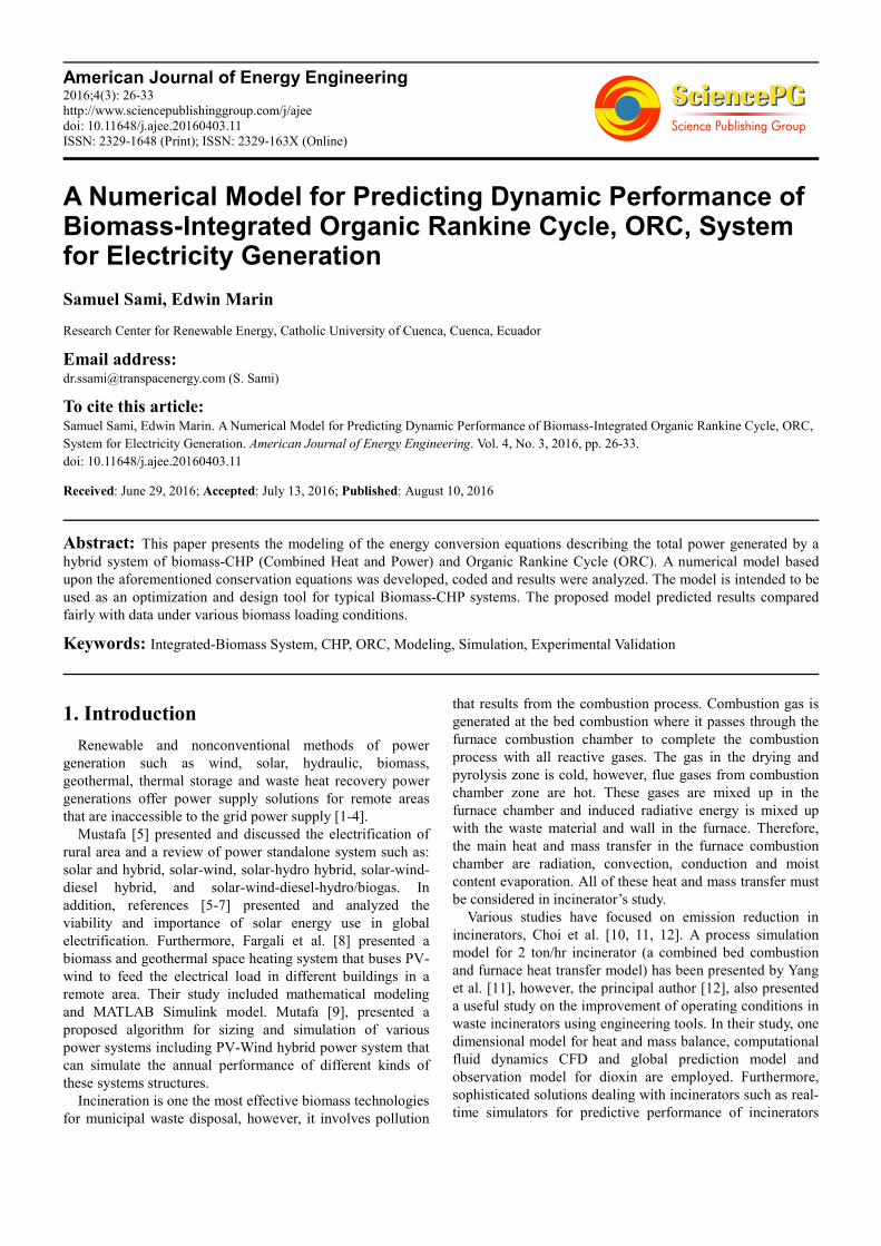
Figure 1. Biomass integrated ORC/CHP system [16, 17].
Readers interested in further details of the efficient use of
ORC where a vapor turbine generator unit is used to generate
electricity as shown in Figure 1 are advised to consult
reference Sami [16]. The flue gas from the incinerator
combustion chamber heats up the thermal oil in the heat
exchanger heater and exits to the ambient at lower
temperature to reduce its impact on the environment since the
thermal oil heat exchanger tank acts as a scrubber. The heated
thermal oil is circulated to the waste heat boiler (WHB) of
the ORC where the refrigerant vapor is generated. The
saturated or slightly superheated vapor expands in the vapor
turbine of the ORC, where electricity is generated at the
generator end of the vapor turbine and supplied to the grid
through switch gear. The expanded low pressure is
condensed in the condenser and pumped to the WHB to
compete the ORC cycle [16]. It has been reported by Sami
[16] that the ORC performance can be enhanced significantly
by using refrigerant mixtures. This study employs refrigerant
mixtures in the analysis of the ORC. The following
thermodynamic equations can be written to evaluate the
performance of the ORC [16];
,-./ � "012 ���4�$5 $6� (7)
�789 � "789 ���4�$5 $:� (8)
American Journal of Energy Engineering 2016; 4(3): 26-33 28
Heat balance at the ORC is as follows;
���'��;<=��� �>�=���4�$5 $6�-Qc-Wp (9)
"-./ � 7?@A
BCDE (10)
Equation (10) defines the net biomass ORC efficiency that
includes all losses and power consumed by accessories of the
biomass combined heat and power hybrid system. The
thermodynamic properties of the refrigerant circulating on
the ORC is determined by REFPROP [16].
The energy balance on the bio-mass flue gas thermal oil
heater [8, 15] can be used to estimate the thermal oil
temperature time-variation in the heater tank;
F�/FH��' � ���/I���0<J;<=
K0;LM;<=�
NM�JOP;<=/I;<=
�;<=/I;<=�0QK0R�
NM�JOP;<=/I;<= (11)
Where,
�����: Combustion heat added
���� : Radiative heat
�����: Convective heat
�����: Evaporative heat
Qc: Heat released by condenser
T: is the temperature thermal oil in heat exchanger tank
S��': Density of thermal oil ! ��c: Volume of heater
����: Mass flow rate of flue gas
����: Biomass waste mass material
���4: Mass flow rate ORC cycle refrigerant
,-./ : Work generated at ORC vapor turbine generator
"-./: ORC thermal efficiency
The Biomass-CHP energy conversion efficiency of the
hybrid system can be obtained by;
"9������ � 7?@A
Bd;ef (12)
Where ����� is defined as follows;
����� � 4.18�!�������"��� (13)
Where;
�!���: Calorific heat value of bio-gas
"���: Biomass furnace efficiency
Numerical Procedure
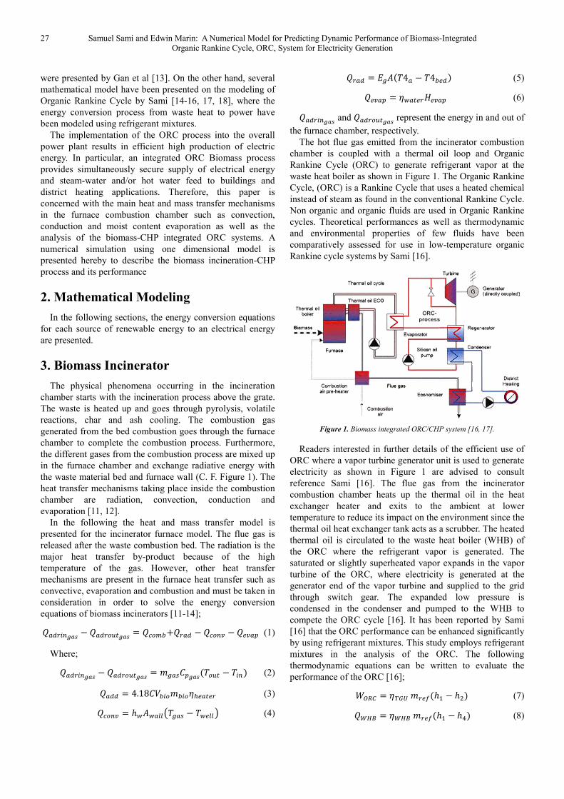
The energy conversion and heat transfer mechanisms
taking place during various processes shown in Figure 1, are
described in Equations (1) through (13). These equations
have been solved as per the logical flow diagram presented in
Figure 2, where the input parameters of Biomass, as well as
the ORC and independent parameters are defined. Dependent
parameters were calculated and integrated in the system of
finite-difference formulations. Iterations were performed
until a solution is reached with acceptable iteration error.
The numerical procedure starts with using the biomass
loading to calculate the mass flow rate of flue gas, thermal
oil, and refrigerant circulating in various loops under
specified conditions. The thermodynamic and thermophysical
properties of flue gas, thermal oil, and refrigerant are
determined based upon the initial conditions of the biomass
incinerator loading, lower heating value, air flow rate, excess
air ratio, and combustion products. This follows by using the
finite-difference formulations to predict the time variation of
the oil tank temperature as well as other hybrid system power
outputs and efficiencies. Finally, hybrid system efficiency is
calculated at each input condition.
Figure 2. Flow diagram of Hybrid system; biomass and CHP calculation.
4. Results and Discussion
In order to solve the aforementioned equation (1) through
(13) and, taking into account that total power may not be
simultaneous, and for validation purposes, this simulation
model and the above mentioned equations were coded with
finite-difference formulations. In addition, for the purpose of
validation and tuning up the predicted output simulated results,
the data was used to validate the simulation program under
various conditions. In the following sections, we present
analysis and discussions of the numerical results predicted as
well as validations of the proposed simulation model.
4.1. Biomass Simulation
Equations (1) through (13) present the heat and mass
calculation balance at the combustion chamber where the
solid waste is fed and process of combustion releases heat
29 Samuel Sami and Edwin Marin: A Numerical Model for Predicting Dynamic Performance of Biomass-Integrated
Organic Rankine Cycle, ORC, System for Electricity Generation
which is converted to the gas and ash through chemical
reactions. Three loading of municipal solid waste (MSW)
incinerators were considered for this study; 100, 150 and 200
t/d with lower heating values (LHV) of 1000, 1700 and 2300
kcal/kg for the simulation. The low quality waste
compositions for the simulation were 59% moisture, ash 8%
and combustible 33% [12]. The maximum excess air ratio
was 1.76-2 for the waste of high quality (LHV=2300 kcal/kg)
and the minimum excess air ratio was 1.05-1.26 for the waste
of low quality (LHV=1000 kcal/kg). This is necessary to
maintain the furnace temperature exit within the range of
850-950°C to ensure complete combustion [12]. Yang et al.
[12 reported that increasing the excess air results in
decreasing the combustion gas. It is also worth mentioning
that as reported by Yang et al. [12] carbon and hydrogen
contents contribute to increase the heating value of waste
material. In the waste material selected the carbon and
hydrogen contents were 14% and 2.24%, respectively.
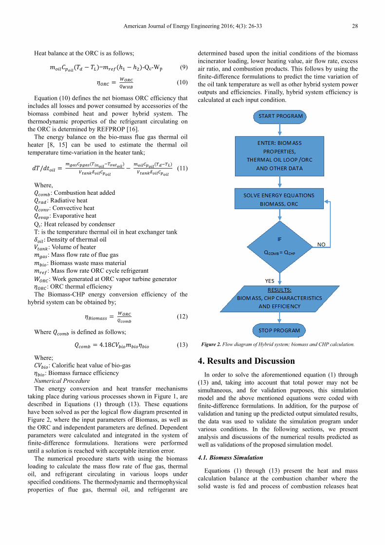
The predicted results of the biomass simulation at different
conditions are presented in Figures 3 through 19. In
particular, Figures 3 and 6 depict the biomass output power at
the ORC generator end as a function of the lower heating
value (LHV) and flue gas flue rate for loading of 200 t/d. It is
quite evident that waste material with higher LHV increases
the output power and similarly higher flue gas flow rates
increases the biomass output power. Similar behavior was
observed at other waste material loadings.
Figure 3. Biomass output power at 200 t/d biomass loading and different
LHV.
Figure 4. Biomass output power at 200 t/d biomass loading and different
flue gas flows.
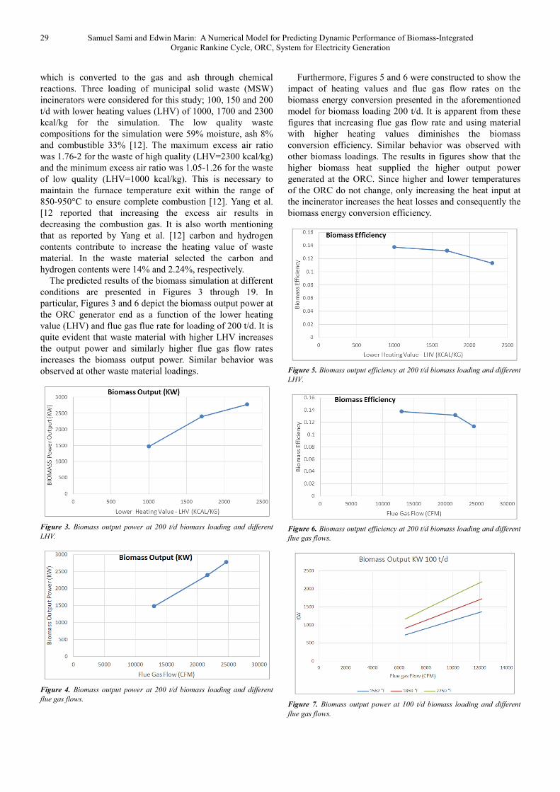
Furthermore, Figures 5 and 6 were constructed to show the
impact of heating values and flue gas flow rates on the
biomass energy conversion presented in the aforementioned
model for biomass loading 200 t/d. It is apparent from these
figures that increasing flue gas flow rate and using material
with higher heating values diminishes the biomass
conversion efficiency. Similar behavior was observed with
other biomass loadings. The results in figures show that the
higher biomass heat supplied the higher output power
generated at the ORC. Since higher and lower temperatures
of the ORC do not change, only increasing the heat input at
the incinerator increases the heat losses and consequently the
biomass energy conversion efficiency.
Figure 5. Biomass output efficiency at 200 t/d biomass loading and different
LHV.
Figure 6. Biomass output efficiency at 200 t/d biomass loading and different
flue gas flows.
Figure 7. Biomass output power at 100 t/d biomass loading and different
flue gas flows.
American Journal of Energy Engineering 2016; 4(3): 26-33 30
The output and efficiency of lower biomass loading
namely 100 t/d, have been presented in Figures 7 through 9.
It is quite evident from these figures that the biomass thermal
behavior is similar to the 200 t/d presented in the previous
figures. However, it appears from figures 7 and 8 that the
biomass output is significantly influenced by the flue gas
temperatures, flow rates and obviously the heating value of
the biomass material. Furthermore, the results displayed in
those figures show that the maximum biomass output is
achieved at higher flue gas flow rates and temperatures.
Figure 8. Biomass output power at 100 t/d biomass loading and different
LHV.
Figure 9. Biomass output efficiency at 100 t/d biomass loading and different
flue gas flows.
On the other hand, Figure 9 has been constructed to show
the major parameters that influence the biomass efficiency at
100 t/d. The results displayed in that figure clearly show that
the efficiency is maximized at efficient combustion that
results in flue gas with higher temperatures. However, the
results of this figure also show that integrated biomass
system with CHP i.e. ORC has an efficiency that is limited
by the thermodynamic and thermophysical properties of the
refrigerant used in the ORC.
Furthermore, it is worthwhile noting that Figures 10
through 13 constructed for 200 t/d, show that similar
behavior has been observed with other biomass loadings.
Furthermore, at each particular value of biomass loading,
lower heating value (LHV) as well as specific flue gas flow
rate, results show that the higher the flue gas temperature the
higher the biomass efficiency.
Figure 10. Biomass power output at different flue gas flows.
Figure 11. Biomass output power at different LHV.
Figure 12. Biomass output efficiency at different flue gas flows.
Figure 13. Biomass output efficiency at different LHV.
31 Samuel Sami and Edwin Marin: A Numerical Model for Predicting Dynamic Performance of Biomass-Integrated
Organic Rankine Cycle, ORC, System for Electricity Generation
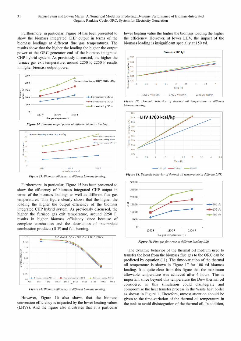
Furthermore, in particular, Figure 14 has been presented to
show the biomass integrated CHP output in terms of the
biomass loadings at different flue gas temperatures. The
results show that the higher the loading the higher the output
power at the ORC generator end of the biomass integrated
CHP hybrid system. As previously discussed, the higher the
furnace gas exit temperature, around 2250 F, 2250 F results
in higher biomass output power.
Figure 14. Biomass output power at different biomass loading.
Figure 15. Biomass efficiency at different biomass loading.
Furthermore, in particular, Figure 15 has been presented to
show the efficiency of biomass integrated CHP output in
terms of the biomass loadings as well as different flue gas
temperatures. This figure clearly shows that the higher the
loading the higher the output efficiency of the biomass
integrated CHP hybrid system. As previously discussed, the
higher the furnace gas exit temperature, around 2250 F,
results in higher biomass efficiency since because of
complete combustion and the destruction of incomplete
combustion products (ICP) and full burning.
Figure 16. Biomass efficiency at different biomass loading.
However, Figure 16 also shows that the biomass
conversion efficiency is impacted by the lower heating values
(LHVs). And the figure also illustrates that at a particular
lower heating value the higher the biomass loading the higher
the efficiency. However, at lower LHV, the impact of the
biomass loading is insignificant specially at 150 t/d.
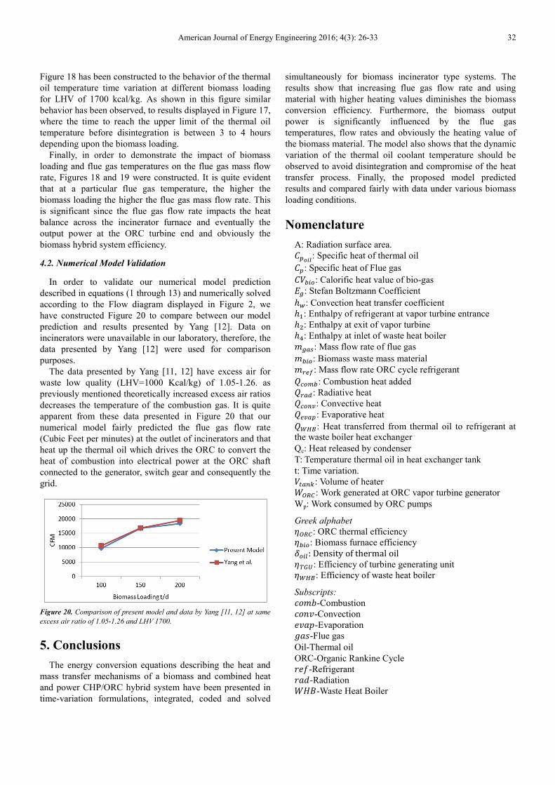
Figure 17. Dynamic behavior of thermal oil temperature at different
biomass loading.
Figure 18. Dynamic behavior of thermal oil temperature at different LHV.
Figure 19. Flue gas flow rate at different loading (t/d).
The dynamic behavior of the thermal oil medium used to
transfer the heat from the biomass flue gas to the ORC can be
predicted by equation (11). The time-variation of the thermal
oil temperature is shown in Figure 17 for 100 t/d biomass
loading. It is quite clear from this figure that the maximum
allowable temperature was achieved after 4 hours. This is
important since beyond this temperature the Dow thermal oil
considered in this simulation could disintegrate and
compromise the heat transfer process in the Waste heat boiler
as shown in Figure 1. Therefore, utmost attention should be
given to the time-variation of the thermal oil temperature in
the tank to avoid disintegration of the thermal oil. In addition,
American Journal of Energy Engineering 2016; 4(3): 26-33 32
Figure 18 has been constructed to the behavior of the thermal
oil temperature time variation at different biomass loading
for LHV of 1700 kcal/kg. As shown in this figure similar
behavior has been observed, to results displayed in Figure 17,
where the time to reach the upper limit of the thermal oil
temperature before disintegration is between 3 to 4 hours
depending upon the biomass loading.
Finally, in order to demonstrate the impact of biomass
loading and flue gas temperatures on the flue gas mass flow
rate, Figures 18 and 19 were constructed. It is quite evident
that at a particular flue gas temperature, the higher the
biomass loading the higher the flue gas mass flow rate. This
is significant since the flue gas flow rate impacts the heat
balance across the incinerator furnace and eventually the
output power at the ORC turbine end and obviously the
biomass hybrid system efficiency.
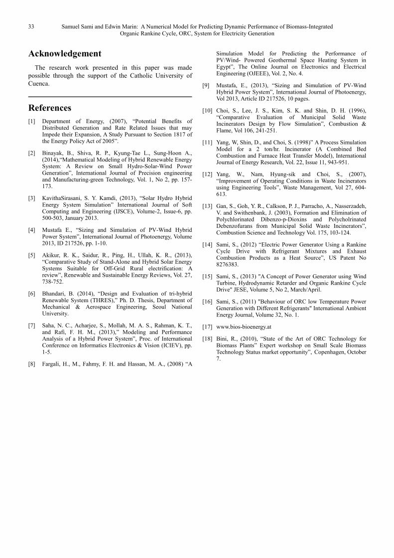
4.2. Numerical Model Validation
In order to validate our numerical model prediction
described in equations (1 through 13) and numerically solved
according to the Flow diagram displayed in Figure 2, we
have constructed Figure 20 to compare between our model
prediction and results presented by Yang [12]. Data on
incinerators were unavailable in our laboratory, therefore, the
data presented by Yang [12] were used for comparison
purposes.
The data presented by Yang [11, 12] have excess air for
waste low quality (LHV=1000 Kcal/kg) of 1.05-1.26. as
previously mentioned theoretically increased excess air ratios
decreases the temperature of the combustion gas. It is quite
apparent from these data presented in Figure 20 that our
numerical model fairly predicted the flue gas flow rate
(Cubic Feet per minutes) at the outlet of incinerators and that
heat up the thermal oil which drives the ORC to convert the
heat of combustion into electrical power at the ORC shaft
connected to the generator, switch gear and consequently the
grid.
Figure 20. Comparison of present model and data by Yang [11, 12] at same
excess air ratio of 1.05-1.26 and LHV 1700.
5. Conclusions
The energy conversion equations describing the heat and
mass transfer mechanisms of a biomass and combined heat
and power CHP/ORC hybrid system have been presented in
time-variation formulations, integrated, coded and solved
simultaneously for biomass incinerator type systems. The
results show that increasing flue gas flow rate and using
material with higher heating values diminishes the biomass
conversion efficiency. Furthermore, the biomass output
power is significantly influenced by the flue gas
temperatures, flow rates and obviously the heating value of
the biomass material. The model also shows that the dynamic
variation of the thermal oil coolant temperature should be
observed to avoid disintegration and compromise of the heat
transfer process. Finally, the proposed model predicted
results and compared fairly with data under various biomass
loading conditions.
Nomenclature
A: Radiation surface area.
��;<=: Specific heat of thermal oil
��: Specific heat of Flue gas
�!���: Calorific heat value of bio-gas
*�: Stefan Boltzmann Coefficient
$%: Convection heat transfer coefficient
$5: Enthalpy of refrigerant at vapor turbine entrance
$6: Enthalpy at exit of vapor turbine
$:: Enthalpy at inlet of waste heat boiler
����: Mass flow rate of flue gas
����: Biomass waste mass material
���4: Mass flow rate ORC cycle refrigerant
�����: Combustion heat added
���� : Radiative heat
�����: Convective heat
�����: Evaporative heat
�789: Heat transferred from thermal oil to refrigerant at
the waste boiler heat exchanger
Qc: Heat released by condenser
T: Temperature thermal oil in heat exchanger tank
t: Time variation.
! ��c: Volume of heater
,-./ : Work generated at ORC vapor turbine generator
Wp: Work consumed by ORC pumps
Greek alphabet
"-./: ORC thermal efficiency
"���: Biomass furnace efficiency
S��': Density of thermal oil "012: Efficiency of turbine generating unit
"789: Efficiency of waste heat boiler
Subscripts:
gh�i-Combustion
ghjk-Convection
lkmn-Evaporation
omp-Flue gas
Oil-Thermal oil
ORC-Organic Rankine Cycle
qlr-Refrigerant
qmF-Radiation
,+s-Waste Heat Boiler
33 Samuel Sami and Edwin Marin: A Numerical Model for Predicting Dynamic Performance of Biomass-Integrated
Organic Rankine Cycle, ORC, System for Electricity Generation
Acknowledgement
The research work presented in this paper was made
possible through the support of the Catholic University of
Cuenca.
References
[1] Department of Energy, (2007), “Potential Benefits of Distributed Generation and Rate Related Issues that may Impede their Expansion, A Study Pursuant to Section 1817 of the Energy Policy Act of 2005”.
[2] Binayak, B., Shiva, R. P., Kyung-Tae L., Sung-Hoon A., (2014),“Mathematical Modeling of Hybrid Renewable Energy System: A Review on Small Hydro-Solar-Wind Power Generation”, International Journal of Precision engineering and Manufacturing-green Technology, Vol. 1, No 2, pp. 157-173.
[3] KavithaSirasani, S. Y. Kamdi, (2013), “Solar Hydro Hybrid Energy System Simulation” International Journal of Soft Computing and Engineering (IJSCE), Volume-2, Issue-6, pp. 500-503, January 2013.
[4] Mustafa E., “Sizing and Simulation of PV-Wind Hybrid Power System”, International Journal of Photoenergy, Volume 2013, ID 217526, pp. 1-10.
[5] Akikur, R. K., Saidur, R., Ping, H., Ullah, K. R., (2013), “Comparative Study of Stand-Alone and Hybrid Solar Energy Systems Suitable for Off-Grid Rural electrification: A review”, Renewable and Sustainable Energy Reviews, Vol. 27, 738-752.
[6] Bhandari, B. (2014), “Design and Evaluation of tri-hybrid Renewable System (THRES),” Ph. D. Thesis, Department of Mechanical & Aerospace Engineering, Seoul National University.
[7] Saha, N. C., Acharjee, S., Mollah, M. A. S., Rahman, K. T., and Rafi, F. H. M., (2013),” Modeling and Performance Analysis of a Hybrid Power System”, Proc. of International Conference on Informatics Electronics & Vision (ICIEV), pp. 1-5.
[8] Fargali, H., M., Fahmy, F. H. and Hassan, M. A., (2008) “A
Simulation Model for Predicting the Performance of PV/Wind- Powered Geothermal Space Heating System in Egypt”, The Online Journal on Electronics and Electrical Engineering (OJEEE), Vol. 2, No. 4.
[9] Mustafa, E., (2013), “Sizing and Simulation of PV-Wind Hybrid Power System”, International Journal of Photoenergy, Vol 2013, Article ID 217526, 10 pages.
[10] Choi, S., Lee, J. S., Kim, S. K. and Shin, D. H. (1996), “Comparative Evaluation of Municipal Solid Waste Incinerators Design by Flow Simulation”, Combustion & Flame, Vol 106, 241-251.
[11] Yang, W, Shin, D., and Choi, S. (1998)” A Process Simulation Model for a 2 ton/hr. Incinerator (A Combined Bed Combustion and Furnace Heat Transfer Model), International Journal of Energy Research, Vol. 22, Issue 11, 943-951.
[12] Yang, W., Nam, Hyung-sik and Choi, S., (2007), “Improvement of Operating Conditions in Waste Incinerators using Engineering Tools”, Waste Management, Vol 27, 604-613.
[13] Gan, S., Goh, Y. R., Calkson, P. J., Parracho, A., Nasserzadeh, V. and Swithenbank, J. (2003), Formation and Elimination of Polychlorinated Dibenzo-p-Dioxins and Polycholrinated Debenzofurans from Municipal Solid Waste Incinerators”, Combustion Science and Technology Vol. 175, 103-124.
[14] Sami, S., (2012) “Electric Power Generator Using a Rankine Cycle Drive with Refrigerant Mixtures and Exhaust Combustion Products as a Heat Source”, US Patent No 8276383.
[15] Sami, S., (2013) "A Concept of Power Generator using Wind Turbine, Hydrodynamic Retarder and Organic Rankine Cycle Drive" JESE, Volume 5, No 2, March/April.
[16] Sami, S., (2011) "Behaviour of ORC low Temperature Power Generation with Different Refrigerants" International Ambient Energy Journal, Volume 32, No. 1.
[17] www.bios-bioenergy.at
[18] Bini, R., (2010), “State of the Art of ORC Technology for Biomass Plants” Expert workshop on Small Scale Biomass Technology Status market opportunity”, Copenhagen, October 7.