A Overview of Software A.1 Introduction Quite extensive software tools have become available over the last 10 – 15 years. A brief overview over some of the main tools which are oriented towards offshore/oil and gas applications are presented in this appendix. These tools have been categorised into the following: QRA software QRA software tools for scenario and probability analysis QRA software tools for consequence analysis Risk management software Qualitative risk assessment software Reporting and analysis of incidents and accidents. Brief summaries are presented as an overview, followed by brief sections presen- ting some of the main characteristics of these products. These summaries have been prepared by the software vendors. Only those products are detailed where a response was received from the vendors. The descriptions are structured as follows: Name and purpose of software Scope of software License conditions, pricing etc It should be stressed that there is a large amount of general software tools for CFD from many different suppliers. These have not been included in the presentations that follow throughout this appendix. Some of these may have quite valid applications during estimation of loads from fire or explosion, or for gas dispersion or oil slick movements. Because there are so many software tools available in this
Transcript
A
Overview of Software
A.1 Introduction
Quite extensive software tools have become available over the last 10 – 15 years. A brief overview over some of the main tools which are oriented towards offshore/oil and gas applications are presented in this appendix. These tools have been categorised into the following:
QRA software QRA software tools for scenario and probability analysis QRA software tools for consequence analysis Risk management software Qualitative risk assessment software Reporting and analysis of incidents and accidents.
Brief summaries are presented as an overview, followed by brief sections presen-ting some of the main characteristics of these products. These summaries have been prepared by the software vendors. Only those products are detailed where a response was received from the vendors. The descriptions are structured as follows:
Name and purpose of software Scope of software License conditions, pricing etc
It should be stressed that there is a large amount of general software tools for CFD from many different suppliers. These have not been included in the presentations that follow throughout this appendix. Some of these may have quite valid applications during estimation of loads from fire or explosion, or for gas dispersion or oil slick movements. Because there are so many software tools available in this
524 Appendix A: Overview of Software
category, it becomes impossible to give an overview of all relevant tools. None of these are therefore included.
Software tools that are only directed at onshore usage are not included in the reviews, neither are tools for production/transport regularity analysis.
All software tools that are mentioned in the following are commercially available from the vendor as listed.
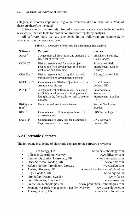
Table A.1. Overview of software for quantitative risk analysis
Software Purpose Contact ASAP® 3D geometrical description and analysis of a
fixed set of event trees Lilleaker Consulting, Oslo, Norway
COSAC® Risk assessment tool for early project phases of a field development for concept evaluation and screening
Scandpower Risk Management, Kjeller,Norway
CRA Tool® Risk assessment tool to rapidly risk rank various offshore development concepts
SAFETI® Comprehensive QRA tool for Flammable, Explosive and Toxic Impact
DNV Software, London, UK
A.2 Electronic Contacts
The following is a listing of electronic contacts to the software providers:
ERS Technology, UK www.erstechnology.com Lilleaker Consulting, Norway www.lilleaker.com Century Dynamics, Horseham, UK www.autoreagas.com DNV Software, london, UK www.dnv.com Safetec Nordic, Trondheim, Norway www.safetec.no Atkins, Glasgow, UK www.atkinsglobal.com/oilandgas EQE, London, UK www.eqe.co.uk Fire Safety Design, Sweden www.fsd.se Four Elements, London, UK www.erm.com Prediction Technologies Inc www.prediction–technologies.com Scandpower Risk Management, Kjeller, Norway www.scandpower.no Atkins, Bristol, UK www.atkinsglobal.com
Appendix A: Overview of Software 525
Table A.2. Overview of QRA software for scenario and probability risk analysis
Software Purpose Contact BlowFAM® Evaluation of blowout risk during specific
well operations Scandpower, Kjeller, Norway
COAST® Shipping traffic database, using GIS for user interface and graphical pres. of information on shipping routes and vessel characteristics
Safetec Nordic, Trondheim, Norway
COLLIDE® Analysis of collision risk between vessels and platforms
Safetec Nordic, Trondheim, Norway
DATABASEMANAGER®
For storage, handling, and display of reliability analysis data
ERS Technology, UK
EGRESS® Mustering and evacuation simulation for evacuation/rescue modelling
ERS Technology, UK
LEAK® Calculation of the frequency of leaks at an installation
DNV Software, London, UK
RDAT–Plus® Bayesian data analysis Prediction Techno-logies, MD, USA
CARA–FaultTree®
Fault tree analysis and construction Safetec Nordic, Trondheim, Norway
Table A.3. Overview of QRA software for consequence analysis
Software Purpose Contact AutoReaGas® CFD–based explosion simulation Century Dynamics,
Horseham, UK FIREX® Empirical prediction of main fire
characteristics and responses Scandpower Risk Management, Kjeller,Norway
FLACS® Explosion simulation Gexcon, Bergen, N KAMELEONFireEx–KFX®
Fire and gas dispersion simulation ComputIT, Trondheim, Norway
MONA® Advanced tool for simulation of single–comp. multiphase systems
Scandpower Risk Management, Kjeller,Norway
OLGA® Transient multiphase flow simulator for systems comprising flow lines, risers and process equipment.
Scandpower Risk Management, Kjeller,Norway
PHAST® Windows–based toolkit for determi-nation of consequences of accidental releases of hazardous material
DNV Software, London, UK
Gexcon, Bergen, Norway www.gexcon.com ComputIT, Trondheim, Norway www.computit.no Relcon, Stockholm, Sweden www.relcon.se Scandpower Petroleum Technology, Norway www.scandpowerpt.com
526 Appendix A: Overview of Software
Table A.4. Overview of software for qualitative risk analysis
Software Purpose Contact PHA–Pro® Hazard recording and reporting tool,
including four Process Hazard Analysis techniques; HAZOP, What If/Checklist, FMEA and Preliminary Hazard Analysis
DNV Software, London, UK
PHAROS® Integration of job hazard analysis process with the Permit to Work System
EQE, London, UK
Kyrass® Safety management through a hazards register
Safetec Nordic, Trondheim, Norway
Sabaton® FMEA and FMECA analysis Safetec Nordic, Trondheim, Norway
Table A.5. Overview of software for accident/incident analysis
Software Purpose Contact ProSafe® Registration of information from unplanned
occurrences, including analysis and reporting capabilities for trends and patterns to be defined
EQE, London, UK
Synergi® Registration analysis and reporting of information from incidents, accidents and unplanned occurrences
Pride, Stavanger, Norway
A.3 Quantitative Risk Analysis Software
A.3.1 ASAP®
The following is a brief description of this software, the function, vendor, pricing and main features.
Function 3D geometrical description and analysis of a fixed set ofevent trees
Vendor Lillesoft a.s., Baerum, Norway Pricing License fee using ASAP on the Lillesoft Terminal Server:
NOK 160,000 (12 months) NOK 90 000 (6 months)NOK 50,000 (3 months)NOK 20,000 (1 month) Prices valid through 2006.
ASAP® is a computer analysis package that calculates the risk related to hydrocar-bon leaks, fires and explosions on oil and gas installations. Complex interactions in horizontal and vertical directions are taken care of by adjusting the models to three–dimensional geometry. Scenarios such as gas and liquid jets followed by gas dispersion and fire development can be seen in 3D graphic, giving a good interpre-tation of the accident.
Registration and management of hazards Atkins, Bristol, UK
PRISM® Audit tool for Safety Management Assessment of Safety Management performance
ERS Technology, UK
Riskplot II® Risk summation and presentation tool, including outputs of risk contours, F–N data, risk transects and a listing of dominant events
Four Elements, London, UK
ORBITOffshore®
Computer system designed to support the analysis work related to Risk Based Inspection, RBI, for offshore topside systems
DNV Software, London, UK
BowTieXP® Management of major risks to people, the environment, assets and reputation by means of Abow–tie@ graphical interface diagram
Governors BV, Netherlands
THESIS Management of major risks to people, the environment, assets and reputation by means of “bow–tie” graphical interface diagram
ABS Consulting, Warrington, UK
ASAP® consists of a design package, physical and statistical models along with design interface models. The latter constitutes the connection between the physical models and the design. In the design package the user designs the geometry of the installation and the process flow diagram for equipment containing hydrocarbons. All the models are intelligent in the sense that they automatically adjust to the geometry and logic the user defines. This implies that design changes and concept development are catered for in a fast and consistent manner by the program.
ASAP® is currently being re–designed to cope with transient analysis of gas dispersion, detection, ignition and equipment escalation according to NORSOK Z–013 and Statoil/Norsk Hydro internal Guideline for protection of pressurised systems exposed to fire.
A.3.2 COSAC®
The following is a brief description of this software, the function, vendor, pricing and main features.
Function Risk assessment tool for early project phases of a field deve-lopment for concept evaluation and screening
Vendor Scandpower Risk Management, Kjeller, Norway Pricing NOK 120,000 per license.
528 Appendix A: Overview of Software
COSAC® is a computerised tool for efficient risk assessment in the early project phases of a field development.
COSAC® analysis and results are tailor-made for concept evaluation and screening. Its aim is to increase the safety of new offshore developments by utilising 20 years of experience gained from risk analyses. Some of the main features of COSAC® include reducing uncertainty, improving the quality and efficiency of early phase safety evaluations. COSAC® provides a safety score for every risk factor associated with an offshore field development concept. A low score indicates safety concerns and/or lack of documentation of important safety issues. Therefore, a low safety score in COSAC® puts these issues in focus. In addition the user is provided with information on how to resolve the problems identified by COSAC®.
A.3.3 CRA Tool®
The following is a brief description of this software, the function, vendor, pricing and main features.
Function Fast track risk tool that can be used in the assessment ofvarious offshore oil & gas concepts
Vendor Atkins, Glasgow, UK Pricing Contact vendor for information.
The Concept Risk Assessment (CRA) Tool® focuses on the key parameters that drive the risk levels in new offshore oil and gas developments. The model was developed in conjunction with BP and Shell, driven by a requirement to rapidly rank large numbers of concepts in terms of their risks to the asset, personnel and the environment.
The tool has been used to assist in the selection of the best concept for around thirty new oil, gas and condensate developments in the North Sea and worldwide. The novelty is that the risk assessment is based on a number of pre–processed risk building blocks for each item of hazardous equipment. These are then moderated by gearing factors to take account of specific aspects of the design.
A.3.4 NEPTUNE®
The following is a brief description of this software, the function, vendor, pricing and main features.
Function Offshore risk analysis Vendor DNV Software, London, UK Pricing Available upon request
Neptune® is the successor to OHRAT, and was released in 1999. Neptune® is a comprehensive software tool for designing, calculating and providing full tracea-bility of a quantitative risk assessment. The system architecture has been designed to give maximum flexibility with respect to system configurations (client/server,
Appendix A: Overview of Software 529
distributed solutions, data communication, and web solutions). Neptune® contains models for calculation of discharge, dispersion, pool formation and evaporation, flammable and toxic effects and impact. Also contained with Neptune® are models designed for the specific needs of offshore installations, such as smoke generation, endangerment of muster areas, collision with ships, and many more. In addition, special attention has been given to allow users to incorporate new models. Neptune® offers flexible modelling of hazards and risks through a wide range of analytic capabilities including consequence modelling, event tree modelling, leak frequency calculations, sensitivity and what–if analysis. Neptune® is based on a very simple concept; data flows from one model to another model along specified paths. Data is input only once, and if a change is made anywhere within the study this will be carried along the specified paths and affect the rest of the study. Neptune® operates under MS–Windows® and has tools like Excel® (incl. Visual Basic®) fully integrated.
A.3.5 PLATO
The following is a brief description of this software, the function, vendor, pricing and main features.
Function 3D geometrical platform model including representation ofsafety related engineering components and design features,analysing explicitly development and timing of escalating hazards, fire, explosion and structural collapse
Vendor Environmental Resources Management (ERM), London, UK Pricing GBP 36,000 (leasing schemes also available)
Optional annual maintenance: GBP 3,000 per year (telephone support and free minor software revisions).
PLATO uses a 3D model of the platform in which all safety related engineering components and design features are explicitly represented. The development and timing of escalating hazards such as fire, explosion and structural collapse are simulated with automatic generation of scenarios where safety related components affect the outcome. Results can be processed not only for the overall level of socie-tal and individual risk but also to determine the primary escalation mechanisms and key safety critical equipment. The primary benefits over event tree methods are modelling realism, auditability, explicit representation of geometry/time and ease of update for evaluation of design options or platform modifications.
A.3.6 RiskSpectrum®
The following is a brief description of this software, the function, vendor, pricing and main features.
Function Fault tree and event tree software Vendor Relcon AB, Stockholm, Sweden Pricing Contact RELCON for pricing.
530 Appendix A: Overview of Software
RiskSpectrum® PSA Professional offers an intuitive user interface for modelling everything from the basic fault tree with AND and OR–gates to advanced fault tree and event tree integration of sequences in linked event trees with boundary condi-tions and CCF events.
The integrated analysis tool (RSAT) is specially designed for solving large PSA models and offers MCS (minimal cut set), sensitivity, importance and time dependent analysis. RiskSpectrum® PSA Professional also includes an MCS editor and an advanced post-processing function. The software has the following analysis functions:
Powerful analysis functions based on a fast cut set algorithm, which generates and stores minimal cut sets (MCS). For any existing MCS–table, RiskSpectrum® calculate uncertainty, impor-tance, sensitivity, and time dependent reliability measures. Analyses can be carried out on several levels: Any fault tree gate, any indi-vidual event tree sequence, any consequence (every event tree sequence can be assigned one or more consequences, e.g. a plant damage state). An analysis case can specify a ‘boundary condition set’ which includes a list of logical settings to apply to the model. The boundary condition set can include settings of true/false state for house events, basic events and gates. This is very useful both for running analysis of the same base model, but with different variations, or for sensitivity analysis. Analysis groups can be used for defining complex sets of up to thousands of analysis runs carried out in an automated sequence. This is particularly valuable when re–calculating the entire PSA. Success top events in event trees are handled both qualitatively and quanti-tatively.
RiskSpectrum® Professional is specially designed to fulfil the demands for complete Probabilistic Safety Assessment (PSA) software tool for nuclear power installations.
Linking between event trees and fault trees, and linking of “chains” of event trees House events and exchange events for complex variations of a base model, which makes it easy to manage different plant configurations, specialisa-tion of models for different initiating events and/or different accident sequences. These features are particularly valuable in carrying out external event analyses. CCF groups for automated CCF quantification based on several different CCF models.
Fully graphical event and fault tree editors and inherent Windows functions such as cut, copy, paste and drag–and–drop makes RiskSpectrum® Professional easy to learn and use.
RiskSpectrum® Professional uses an ‘open’ database format utilising the Microsoft Access format. Each of the database tables is essentially ‘unlimited’ in
Appendix A: Overview of Software 531
terms of number of records, except the obvious limit in available space on the storage media (hard disk).
A.3.7 RISK®
The following is a brief description of this software, the function, vendor, pricing and main features.
Function Comprehensive offshore quantitative risk assessment tool Vendor ERS Technology, UK Pricing Not available.
RISK® is a linked spreadsheet QRA model developed on EXCEL®. It enables users to clearly identify the key stages of the risk assessment process and follow individual major hazard events from their initiation, through accident development, to the contribution they make to accident scenarios, TR Impairment, individual risk and PLL. Key features of RISK® are:
Developed using industry standard spreadsheet software package (EXCEL®).Is user friendly and can be interrogated by engineers without the need for formal training. Is easy to tailor to meet specific project requirements. Is transparent and focuses on key scenarios at an appropriate level of detail.
A.3.8 SAFETI®
The following is a brief description of this software, the function, vendor, pricing and main features.
Function Comprehensive QRA software tool for flammable, explosive and toxic impact
Vendor DNV Software, London, UK Pricing Available on request.
SAFETI® (Software for the Assessment of Flammable, Explosive and Toxic Im-pact) is the most comprehensive and widely used onshore QRA package available. It is a Windows® based system that provides a user friendly, industry standard method for quantifying major chemical risks. It enables analysis of the likelihood and severity of major hazards and makes use of the PHAST® models to predict the consequence of major releases. By combining these with their frequencies and taking account of population location and density, along with ignition source location for flammable and explosive effects, a number of presentations of 'risk' are possible. These include risk contours, F/N curves, risk transects and risk ranking at specific points.
532 Appendix A: Overview of Software
A.4 QRA Tools for Scenario and Probability Analysis
A.4.1 BlowFAM®
The following is a brief description of this software, the function, vendor, pricing and main features.
Function Evaluation of blowout risk during specific well operationsthrough assessment of approximately 300 elements, whichinfluence the probability of a blowout
membership of ‘Sintef Offshore Blowout Batabase’. Membership of BlowFAM steering committee: NOK 250,000 (includes three user licences). Use of BlowFAM® in projects on royalty basis: NOK 40,000.
BlowFAM® is a PC–tool for evaluation of blowout risk during specific well opera-tions. BlowFAM® has been developed in close co–operation with drilling/well intervention professionals in the participating companies. In addition, drilling specialists from several contractor companies have contributed.
The BlowFAM® model has identified approximately 300 elements, that influence the probability of a blowout. Many of these are applicable for the whole well life while others are only relevant for a specific well phase, e.g. drilling of the well. These elements are rated in regard to their importance to the risk. Main risk contributors for a specific development can be identified and cost–efficient risk reducing measures may be implemented.
The BlowFAM® model is also a valuable tool for communicating risk elements to the drilling professionals involved in the well operations.
A.4.2 COAST®
The following is a brief description of this software, the function, vendor, pricing and main features.
Function Shipping traffic database holding details on regular shippingtraffic on the Norwegian and UK Continental Shelves as well as other areas of the world. Includes graphical presentation ofinformation on shipping routes and vessel characteristics using GIS
Vendor Safetec Nordic, Norway Pricing Not available.
COAST® is a shipping traffic database that operates on a GIS platform, and holds detailed information on the regular shipping traffic on the Norwegian and UK continental shelves, as well as other areas of the world. The data in COAST® is presented as shipping routes, where each route contains information such as the
Appendix A: Overview of Software 533
annual number of vessels on the route, distribution of vessel types and sizes, route width (std. dev.), etc. COAST® facilitates searches around user–defined positions to identify the traffic pattern, traffic density and vessel characteristics inside the search area, as well as distance and bearing from the search position. The GIS program automatically plots the identified routes on electronic charts.
COAST® was developed by Safetec during 1995/96 in a project funded by UKOOA, HSE and DETR and successfully achieved its main objective which was to provide a comprehensive, up–to–date and easy to use database on shipping movements which could be used to assess risks between shipping and offshore installations in UK waters. In 2002 COAST Norway® was developed, funded by the OLF, providing a much more comprehensive and detailed coverage of Norwegian waters, in addition to the North Sea.
The main data sources for COAST® are Lloyd’s port log data, AIS data, radar data and a large number of traffic surveys. Additional surveys and data collections are undertaken each year to maintain the accuracy of the system. A new platform for COAST® is being developed, to meet the requirements of new and much more comprehensive data sources that have become available.
A.4.3 COLLIDE®
The following is a brief description of this software, the function, vendor, pricing and main features.
Function Analysis of collision risk between vessels and platforms Vendor Safetec Nordic, Norway Pricing Not available.
COLLIDE® is a collision risk tool developed by Safetec under the sponsorship of offshore operators in the UK, Norwegian, Danish, German and Dutch sectors to assist in the assessment of ship collision risk. The tool has the primary function of calculating the frequency and consequence of ship impacts against any offshore structure.
The system provides models for assessing the risks associated with passing (merchant, tankers, fishing, standby, supply) and visiting traffic (alongside installa-tions, standby, supply) and gives consideration to both drifting and powered colli-sion scenarios. The main data source for COLLIDE® is detailed shipping traffic data. This data may come from COAST®, or from other available sources. Other inputs include installation details, environmental data (wind, wave, etc.), vessel characteristics, etc.
The COLLIDE® model has regularly been updated to take into account the effects of technological developments and additional information sources beco-ming available.
A.4.4 Database Manager®
The following is a brief description of this software, the function, vendor, pricing and main features.
534 Appendix A: Overview of Software
Function For storage, handling, and display of reliability analysis data Vendor ERS Technology, UK Pricing Not available.
Database Manager® is a tailored database capable of hosting reliability and safety data. Data can be input or supplied by ERS Technology from its own databases. Database Manager® then enables the data to be configured, searched and analysed, and presented in various reporting formats.
Data Manager® facilitates file and data transfer to and from other databases. It accepts virtually unlimited data input, constrained only by hardware availability. It handles a wide variety of database taxonomies, including all major reliability database taxonomies.
A.4.5 Egress®
The following is a brief description of this software, the function, vendor, pricing and main features.
Function Mustering and evacuation simulation for evacuation/rescuemodelling
Vendor ERS Technology, UK Pricing Not available.
The EGRESS® code allows the movement of large numbers of personnel, such as when mustering on an installation, to be simulated. The platform layout is modelled as a matrix of interconnecting cells. The code covers both the physical movement and behavioural decision-making of personnel. The output is graphical and the movement watched as a real–time graphical representation. It was developed as part of a joint industry project in the UK between ERS Technology, Shell, Texaco, Exxon, and the Health and Safety Executive.
The code has been used both offshore and onshore for the oil and gas and other industries to provide assessments of the movement of people during incidents.
A.4.6 LEAK®
The following is a brief description of this software, the function, vendor, pricing and main features.
Function Calculation of the frequency of leaks at an installation Vendor DNV Software, London, UK Pricing Available on request.
LEAK® is a software tool which calculates the frequency of leaks at an installation, typically an oil platform. Each installation is broken down into a number of areas which are themselves split into a number of segments each containing a list of equipment groups. Each equipment group is built up of base elements such as valves, flanges, pipes, etc. LEAK® will calculate the leak frequency for the instal-
Appendix A: Overview of Software 535
lation, area, segment or equipment group based on built-in historical leak frequency data. The total frequency for each user defined category is reported together with each contributor. The model used expresses the frequency of a leak being larger than a certain size as a continuous function of the equivalent hole size diameter. The historical data used in the calculations is read from a database, enabling the most up–to–date data to be included.
A.4.7 R–DAT Plus®
The following is a brief description of this software, the function, vendor, pricing and main features.
Function Bayesian data analysis Vendor Prediction Technologies, Hyattsville, MD, USA Pricing Not available.
R–DAT Plus® is a full–featured Bayesian data analysis package for risk analysts. It is designed for users who need to perform system specific analyses, but who also have a need to develop generic prior distributions based on industry data.
R–DAT Plus® provides the user with a powerful, yet simple and flexible envi-ronment for storing and organising many types of reliability data and related infor-mation. A hierarchical structure enables the user to develop functional or structural or any other type of breakdown, at any level of detail. The elements of this hier-archy act as folders containing the reliability data and the results of Bayesian analyses performed on the data sets.
With R–DAT® the user may specify the prior distribution in many different ways depending on the type and level of information available. These include a wide variety of parametric distributions (e.g., lognormal, beta and loguniform) using any of a number of input options such as lower and upper bounds, mean and variance, or the distribution parameters. Furthermore, R–DAT® enables the user to develop generic distributions based on industry data (counts of failures in other plants) as well as expert estimates. The resulting distributions will represent the plant–to–plant variability of failure rate of a given class of components or initiating events, and can be used in a plant specific analysis in order perform the Two–Stage Bayesian procedure.
A.4.8 CARA–Fault Tree®
The following is a brief description of this software, the function, vendor, pricing and main features.
Function Fault tree analysis and construction Vendor Sydvest Software (www.sydvest.com) Pricing The price for a single user license is NOK 12,000 (app-
roximately USD 1,450/EUR 1,750).
536 Appendix A: Overview of Software
CARA–FaultTree® is our tool for fault tree analysis and construction. A fault tree is a logical diagram that displays the interrelationships between a potential critical event (accident) in a system and the reasons for this event. By constructing a fault tree you analyse how a system can fail, and the analysis also gives you insight into how the components contributes to the system reliability. With its intuitive graphical user interface, the program lets you create fault trees in a flash. A total of six system performance measures and six measures of component importance are available, along with enhanced report utilities.
A.5 QRA Tools for Consequence Analysis
A.5.1 AutoReaGas®
The following is a brief description of this software, the function, vendor, pricing and main features.
Function Integrated CFD software tool for analysing combustion inflammable gas mixtures and subsequent blast effects.
Vendor Century Dynamics, Horseham, UK Pricing Not available.
AutoReaGas® is a powerful interactive, integrated CFD software tool for analysing combustion in flammable gas mixtures and subsequent blast effects. Industrial applications of the software include risk and safety assessment of offshore plat-forms and onshore petrochemical and process plants, power plants, mining instal-lations and transportation systems.
AutoReaGas® can perform numerical simulation of gas cloud explosions inclu-ding flame propagation, turbulence and the effects of objects in the flow field. The code can also simulate the propagation of resulting blast waves and their interac-tion with structures.
The software is jointly developed by Century Dynamics and TNO and successfully integrates many features of the well known REAGAS®, BLAST® and AUTODYN® codes to provide a unique capability in one commercially available and supported code. The code has been, and continues to be, extensively validated against experimental data.
AutoReaGas® is available as a paid-up licence or as an annual licence and a trial and training is also available.
A.5.2 Firex®
The following is a brief description of this software, the function, vendor, pricing and main features.
Function Prediction of main fire characteristics and responses of firescenarios based on empirical correlations
Appendix A: Overview of Software 537
Vendor Scandpower Risk Management, Kjeller, Norway Pricing PC–software NOK 45,000.
The program system FIREX® is capable of predicting the main fire characteristics and responses of six fire scenarios:
Pool fire in the open Pool fire in enclosure Fire on sea surface Jet fire Diffusive flare fire Fireball/BLEVE.
FIREX® is based on well known prediction methods, which have been compared and verified against experimental data. FIREX® predicts:
Incident heat radiation onto targets not engulfed by the flames, as a function of the distance from the fire. Heat flux to targets engulfed by the flames as a function of time from the onset of the fire. Temperature response of steel structures as a function of time and degree and type of insulation. Smoke production and visibility in smoke as a function of time from the moment of ignition. Pool fire hazard ranges. Fireball hazard ranges. For pool fires in enclosures; ceiling temperature, development of hot gas.
A.5.3 FLACS®
The following is a brief description of this software, the function, vendor, pricing and main features.
Function 3D CFD software tool for analysing gas and air flows inindustrial environments as well as in the atmosphere. Majorapplication areas include ventilation, dispersion and gasexplosions and subsequent blast effects
Vendor Gexcon, Bergen, Norway Pricing Price matrix with various options upon request to
The development of FLACS® has been carried out continuously since 1980 with the co–operation, support, direction and funding of ten international oil and gas companies as well as legislative bodies of three countries. Application specific
538 Appendix A: Overview of Software
validation, wide applicability and efficiency when using FLACS® has been given high priority in the development work.
The software has been used for explosion consequence assessment and risk analysis for more than 300 offshore installations and onshore industrial areas world wide (by Gexcon) and is also used by numerous consultants worldwide (40–50 user groups of FLACS® worldwide, 2006). In addition it is increasingly being used for general industrial CFD analyses, particularly where flows in and around complex geometries is an issue. In recent years it has also been validated for atmo-spheric dispersion use.
Particular characteristics of FLACS® and its application include:
Explosion simulations Any ignition point location Hydrocarbon gases (e.g. any mixture of methane, ethane, propane, butane, ethylene, propylene, acetylene) and hydrogen Variable gas cloud size Variable gas concentration Vent panels: weight, opening mode, opening pressure Yielding walls: failure mode Effect of water spray: nozzle type, flow rate, location Any type of louvered walls, angle of blades, effective openings Prediction of blast wave strength outside the explosion area Effect of inert gases; CO2, N2, and varying O2 concentration .
Dispersion simulations Modelling of gas release Leak source location, size, and direction Forced and natural ventilation conditions Concentration profiles at gas detector locations Jet release/diffusive release Realistic scenario design: Ignition at any time or location during dispersion Exhaust release and dispersion.
Ventilation simulations Modelling of external wind field Modelling of forced/HVAC ventilation Louvre drag factors Air change rates at varying external wind conditions Effect of netting and other blockages Flow velocities in the module and through the louvre Wind chill index calculations Helideck safety assessment.
Appendix A: Overview of Software 539
A.5.4 KAMELEON FireEx–KFX®
The following is a brief description of this software, the function, vendor, pricing and main features.
Function CFD–based tool for prediction of gas dispersion and firecharacteristics and response in complex geometries, as wellas fire mitigation and extinguishment analysis and design
Vendor ComputIT, Trondheim, Norway Pricing Short and long term leasing contracts, licenses ranging from
academic to commercial licenses.
Kameleon FireEx – KFX® is an advanced simulator dedicated to gas dispersion and fire simulation with the following main characteristics:
Three-dimensional transient finite volume CFD code. Includes CAD import capabilities (PDS, PDMS, Flacs macro, others). Interfaced with the finite element structure response codes Fahts/Usfos . Includes detailed lagragian models for fire mitigation by water systems (sprinkler, deluge, curtains, mist etc.).Includes efficient and user friendly pre- and post processor capabilities. Developed by ComputIT/NTNU/Sintef with the partners Statoil, Total, ENI–group, Hydro, ConocoPhillips, Gaz de France, Ruhrgas and Sandia National Laboratories (USA). Used for a large number of industrial analyses world wide for more than 20 years.
Industrial analyses performed by KFX can typically be:
Simulation of all kind of fires; pool fires, jet fires, spray fires, flares, fire in enclosures, in complex congested areas, or in open space. This includes detailed calculation of temperatures, radiation, smoke, visibility, concentra-tions of species, toxic gases, noise etc.Fire impact on structures and process equipment Optimization of passive fire protection Fire temperature, radiation and smoke impact on humans Evaluation of escape routes Simulation and evaluation of fire mitigation by water systems; sprinklers, deluge, mist, curtains Flare simulations; radiation, noise (not standard KFX version), detailed tip simulations Dispersion of gas Calculation of explosive cloud sizes Gas and fire detection systems Combustion in furnaces, engines, furnace design etc.Reduction of emissions; CO, NOx, others
540 Appendix A: Overview of Software
HVAC (ventilation simulations) Turbulent flow analysis with respect to helicopter operations, buildings, environments etcFluid flow and combustion in general 3D visualization, animations, contour plot in real CAD geometry.
A.5.5 Mona®
The following is a brief description of this software, the function, vendor, pricing and main features.
Function Advanced and general tool for simulation of single–component multiphase systems
Vendor Scandpower Risk Management, Kjeller, Norway Pricing To be discussed.
MONA® is an advanced, general tool for simulation of single–component multi-phase systems. MONA can handle general network of pipelines and vessels and thermal non–equilibrium conditions. MONA®'s ability to simulate water hammer and cavitation is validated against loops in Sweden and Germany.
A.5.6 Olga®
The following is a brief description of this software, the function, vendor, pricing and main features.
Function Transient multiphase flow simulator for systems comprisingflow lines, risers and process equipment
Vendor Scandpower Petroleum Technology, Kjeller, Norway Pricing Available as lease for a limited period or as a permanent
licence.
OLGA® is a simulator for transient multi–phase flow phenomena. OLGA® can model general networks of flowlines, risers as well as process equipment.
OLGA® is more accurate in predicting pressure gradients, liquid hold–up, flow regimes and flow rates than competitive models and correlations. OLGA'®s ability to predict release behaviour from condensate pipeline (reflecting bottom topo-graphy), is of significant importance in risk analysis of offshore installations.
OLGA® is verified and validated against more than 10,000 experiments at the two-phase-flow test loop operated by SINTEF in Trondheim.
A.5.7 PHAST®
The following is a brief description of this software, the function, vendor, pricing and main features.
Appendix A: Overview of Software 541
Function Windows–based toolkit for determination of consequences ofaccidental releases of hazardous material
Vendor DNV Software, London, UK Pricing Available on request.
PHAST (Process Hazard Analysis Software Tools) is a Windows–based toolkit, which determines the consequences of accidental releases of hazardous material. It examines the progress of a potential incident from initial release, through forma-tion of a cloud, with or without a pool, to its dispersion. The program uses DNV's unique Unified Dispersion Model (UDM) to apply the appropriate entrainment and dispersion models as the conditions change and to integrate the relevant individual models such that the transition from one behaviour pattern to another is smooth, continuous and automatic. It is applicable to all stages of design and operation across a range of process and chemical industry sectors and may be used to identify situations which present potential hazards to life, property or the environment.
A.6 Qualitative Risk Assessment Software
A.6.1 PHA–Pro®
The following is a brief description of this software, the function, vendor, pricing and main features.
Function Hazard recording and reporting tool, including four process hazard analysis techniques; HAZOP, What If/Checklist, FMEA and Preliminary Hazard Analysis
Vendor DNV Software, London, UK Pricing Available on request.
PHA–Pro® is a Windows based hazard recording and reporting tool which includes four process hazard analysis techniques in a single integrated product. The avail-able techniques are HAZOP, What If/Checklist, FMEA and Preliminary Hazard Analysis. Fully user customisable risk matrices, up to 10 by 10, are available for severity and likelihood ranking of consequence, safeguards and recommendations. Comprehensive recommendation management facilities are available to manage the multitude of recommendations arising from a typical HAZOP study. Other features include wizards to simplify complex tasks, file templates, timed backup and auto recovery, spell checker and all standard windows functionality such as cut, copy and paste, find and replace and drag and drop editing.
A.6.2 PHAROS®
The following is a brief description of this software, the function, vendor, pricing and main features.
542 Appendix A: Overview of Software
Function Integration of job hazard analysis process with the Permit toWork system
Vendor EQE, London, UK Pricing From GBP 5,000 per annum to GBP 50,000 per annum
depending on the number of installations
Pharos® is a powerful system that integrates the job hazard analysis process with the Permit to Work system controlling the planning and execution of hazardous activities. It incorporates many years of EQE's experience in the design and implementation of Permit to Work systems and application of workplace hazard management processes.
The elements within the system include, hazard assessment and job hazard analysis, work tracking and coordination, (including interfaces with maintenance systems), and isolation/lockout control. The system enhances safety with reduced operational costs by the combination of risk assessment methodology and computer technology.
A.6.3 Kyrass®
The following is a short description of this software, its function, vender, pricing and main features.
Function: Safety management Vender: Sydvest Software (www.sydvest.com) Pricing: The price for a single user license is NOK 20,995.
Kyrass® is a software tool designed to help businesses performing safety manage-ment in a practical manner. It is used to establish a register of hazard sources and to manage this register. Kyrass® is used to identify and prioritise risk reducing measures and facilitates the documentation of reviews, revisions and evaluations. The Kyrass® safety management tool is currently a Norwegian tool (i.e. the user interface is in Norwegian).
A.6.4 Sabaton®
The following is a short description of this software, its function, vender, pricing and main features.
Function: FMEA and FMECA analysis Vender: Sydvest Software (www.sydvest.com)
Sabaton FMEA® NOK 9,500 (appr 1,160 EUR / 1,500 USD)
Pricing:
Sabaton FMEA Pro®
NOK 19,500 (appr 2,390 EUR / 3,090 USD).
Sabaton® is an analysis tool supporting FMEA (Failure Mode and Effects Analy-sis) and FMECA (Failure Mode, Effects and Criticality Analysis). FMEA and
Appendix A: Overview of Software 543
FMECA are typically used in product and system development to reveal possible failures and failure modes, and the effects of these failures. The analysis results typically in proposals for design improvement aimed at eliminating system failure or mitigating the effects of component failures. With Sabaton® you simply start a new analysis by selecting analysis form template, or you make your own fully user–defined form. Sabaton® supports you in conducting FMEA and FMECA ana-lyses according to international standards such as ISO 9000, SAE J1739, SAE ARP5580, IEC 60812, BS 5760–5 or MIL–STD 1629.
A.7 Reporting and Analysis of Incidents and Accidents
A.7.1 ProSafe®
The following is a brief description of this software, the function, vendor, pricing and main features.
Function Registration of information from unplanned occurrences, including analysis and reporting capabilities for trends andpatterns to be defined
Vendor EQE, London, UK Pricing From GBP 5,000 to GBP 150,000 depending on the number
of installations
ProSafe® is a Safety & Loss Prevention system developed for the Oil & Gas industry. It captures information from any unplanned occurrence that causes, or has the potential to cause, harm to people, the environment, assets or a company=sreputation. The information is then analysed and reports, (graphs, charts, text), produced. Its data mining capabilities enables trends and patterns to be defined that help focus the deployment of resources to prevent future loss.
Prosafe®=s embedded data dictionary enables companies to change the system to incorporate their own terminology and language. It is also scaleable enabling its use across many geographical locations or as a single departmental system.
A.8 Risk Management Software
A.8.1 Hazard Log Database Management® Tool
The following is a brief description of this software, the function, vendor, pricing and main features.
Function Registration and management of hazards Vendor Atkins, Bristol, UK Pricing STG 7,500, plus tailoring for system / customer requirements
(typically STG 3,000), for a one–off purchase.
544 Appendix A: Overview of Software
The Atkins Hazard Log Database Management® Tool has been developed based upon the Safety Hazard/Risk Management requirements of UK MoD Defence Standard 00–56. It is currently in use on a number of UK MoD defence projects ranging from whole ship projects to shore–based facilities, as well as a tri–national (UK/France/Italy) naval defence communications project.
Furthermore, the Hazard Log Database® has also been tailored for use on the Lewisham Extension to the Docklands Light Railway, and is proposed for a number of other civilian and defence projects in the UK, Europe and Asia.
The Atkins Hazard Log Database Management® Tool is based in Microsoft Access 2®, and can be run on PC or Network facilities.
The clear advantage of the tool is that it provides a systematic and traceable means of managing system safety in accordance with a recognised standard process. It facilitates an effective approach to the management of safety risk reduction measures adopted and actions placed to provide the appropriate levels of confidence in the final safety justification.
Atkins are able to tailor the Database® to the specific needs of the system application under assessment, and the needs of the managing authority.
Each copy of the tool requires an individual licence. Where multiple use is required on a number of system element contracts for
instance, then pricing can be structured differently, and Atkins are open to discus-sion in these matters.
A.8.2 Prism®
The following is a brief description of this software, the function, vendor, pricing and main features.
Function Audit tool for Safety Management Assessment of SafetyManagement performance
Vendor ERS Technology, UK Pricing Not available.
PRISM® is an audit tool that is designed to penetrate each level of an organisation using a structured and systematic methodology. The audit involves both interviews and inspections to build up a picture of both the documented management systems and their implementation.
The code has been used both offshore and onshore for the oil and gas and other industries to provide assessments of the state of development of a company's Safety Management System.
A.8.3 Riskplot II®
The following is a brief description of this software, the function, vendor, pricing and main features.
Function Risk summation and presentation tool, including outputs ofrisk contours, F–N data, risk transects and a listing of domi-nant events
Appendix A: Overview of Software 545
Vendor Four Elements, London, UK Pricing GBP 7,900 for a single user licence.
RISKPLOT® is a risk summation and presentation tool. A regulatory version is currently being developed for UK HSE. Outputs include risk contours, F–N data, risk transects and a listing of dominant events. The risk for each scenario is calculated, accounting for:
wind direction, speed and stability the number of people affected in specified time periods whether populations are indoors/outdoors, fixed (e.g. within dwellings) or mobile (e.g. motorists) topographic effects (e.g. the presence of hills or cliffs) whether event locations are at a fixed point, multiple points or distributed along a line source (e.g. pipeline).
A.8.4 ORBIT Offshore®
The following is a brief description of this software, the function, vendor, pricing and main features.
Function Offshore risk based inspection tool Vendor DNV Software, Høvik, Norway Pricing Available upon request.
ORBIT Offshore® is a software tool that uses DNV's Risk Based Inspection (RBI) technique to help users optimise their inspection management programme. DNV's RBI technique, as described in DNV RP–G 101 “Recommended Practice for Risk–Based Inspection of Topsides Static Mechanical Equipment”, is used to calculate the risk due to corrosion, erosion and cracking for pressure equipment in a marine environment.
ORBIT Offshore® is designed to help users sustain high productivity and reliability of their offshore platforms by minimising lost production and downtime through effective inspection and maintenance. It assists in the management of safety and equipment integrity to user specified levels.
It helps you to achieve these objectives systematically and efficiently. It allows you to quantify the risk for process and utility systems and equipment on topsides and FPSOs. Risk can be defined in terms of potential loss of life, cost, or both. A cost–effective inspection programme can then be devised based on the greatest risk reduction per cost of inspection
A.8.5 BowTieXP® IADC Edition and Black BowTieXP®
The following is a brief description of this software, the function, vendor, pricing and main features.
Function Management of major risks to people, the environment,assets and reputation by means of ‘bow–tie’ graphical inter-face diagram
BowTieXP® is a system which assists companies in the analysis and management of their major risks to people, the environment, assets and reputation. The reports from BowTieXP® can form part of a formal Health, Safety & Environmental Case, can be used for communication to personnel responsible for safety critical activities, and for day–to–day management of the facility. BowTieXP® is available in a special IADC edition that has been optimised to meet the needs and requirements of the offshore industry. BowTieXP® supports the new IADC HSE Case Guidelines and makes the production of HSE Cases easier and more productive. Special IADC HSE Case guideline templates
The BowTieXP® suite of products goes several steps further than other bow–tie tools and allows risk analysis to be ‘tested’ against incident data (Black BowTieXP® add–on). Modelling of simultaneous operations and many other advanced risk analysis features are also available in the BowTieXP® suite of products (Standard, Advanced, Server, RKM Edition, Black BowTieXP®). Also, BowTieXP® and Black BowTieXP® integrate with recognised incident investiga-tion systems like TOP–SET® (which has a proven track record over 20 years), including the new TOP–SET® BlackBox tool for more productive incident investigations.
BowTieXP® provides a structured approach for completing the risk manage-ment process and ensures that controls identified are linked to a company’s busi-ness and to individuals’ responsibilities.
The bow–tie graphical interface diagram provides an extremely useful representation of the risk management process that is readily understood at all levels in a company and also allows for simple data entry.
A.8.6 THESIS
The following is a brief description of this software, the function, vendor, pricing and main features.
Function Management of major risks to people, the environment,assets and reputation by means of ‘bow–tie’ graphical inter-face diagram
Vendor ABS Consulting, Warrington, UK Pricing GBP 500–2,000 per licence depending upon numbers of
licences and modules required.
THESIS (The Health, Environment, Safety Information System) is a software tool that can effectively demonstrate how a facility’s safety management system can be implemented. It assists companies/operators in the analysis and management of the hazards and risks to which their business is exposed, and graphically displays and illustrates the relationship between hazards, controls, risk reduction measures and a business’s HES activities.
Appendix A: Overview of Software 547
THESIS is an application, originally developed by Shell and now jointly with ABS. It has been developed based on the bow–tie concept to visually display how hazards are controlled and how the risk associated with them is reduced to As Low As Reasonably Practicable (ALARP). It documents the provenance of information and the reference sources from which the information is obtained, i.e. it is an ideal audit tool.
The ‘bow–tie’ graphical interface diagram provides an extremely useful repre-sentation of the risk management process that is readily understood at all levels in a company and also allows for simple data entry.
Glossary
The following definitions are coordinated with ISO terminology (ISO/IEC Guide 73:2002) where relevant.
Acceptance criteria (for risk)
Criteria that are used to express a risk level that is considered acceptable for the activity in question, limited to the high level expressions of risk.
Accidental event Event, or chain of events, that may cause loss of life, health, or damage to environment or assets.
Accidental effect The result of an accidental event, expressed as heat flux, impact force or energy, acceleration, etc. which is the basis for the safety evaluation.
Acute release The abrupt or sudden release in the form of a discharge, emission or exposure, usually due to incidents or accidents.
ALARP (As Low as ReasonablyPracticable)
ALARP expresses that the risk level is reduced - through a documented and systematic process - so far that no further measure may be identified, except those that have costs that are grossly disproportionate to the benefits.
Barrier element A component of a barrier system that by itself is not sufficient to perform a barrier function.
Barrier function A function planned to prevent, control, or mitigate undesired events or accidents.
Barrier (or risk) influencing factor
Conditions that influence on the performance of barrier systems.
Barrier system Technical, human and/or organisational measures designed and implemented to perform one or more barrier functions.
BLEVE Boiling liquid expanding vapour explosion, is defined as rupture of a hydrocarbon containing vessel due to being heated by fire loads.
Causal analysis The process of determining potential combinations of circumstances leading to a top event.
550 Glossary
Consequence Outcome of and event. Consequence evaluation
Assessment of physical effects due to accidents, such as fire and explosion loads.
Contingency planning
Planning provision of facilities, training and drilling for the handling of emergency conditions, including the actual institution of emergency actions.
Control (of hazards) Limiting the extent and/or duration of a hazardous event to prevent escalation.
Cost/benefit evaluation
Quantitative assessment and comparison of costs and benefits. In the present context often related to safety measures or environmental protection measures where the benefits are reduced safety or environmental hazard.
Chronic release The continuous or ongoing release in the form of a discharge, emission or exposure.
Defined situations of hazard and accident
A selection of possible events that the emergency preparedness in the activity should be able to handle, based on the activity=s design accidental events, as well as hazardous and accidental situations associated with a temporary increase of risk, and less extensive accidental events.
Design Accidental Event
Accidental events that serve as the basis for layout, dimensioning and use of installations and the activity at large, in order to meet the defined risk acceptance criteria.
Design Accidental Load
The most severe accidental load that the function or system shall be able to withstand during a required period of time, in order to meet the defined risk acceptance criteria.
Dimensioning Accidental Event
See Design Accidental Event
Dimensioning accidental load
See Design Accidental Event
Effectiveness analysis of safety and emergency preparedness measures
Analysis which shall document the fulfilment of functional requirements to safety and emergency preparedness.
Emergency preparedness
Technical, operational and organisational measures that are planned to be implemented under the management of the emergency organisation in case hazardous or accidental situations occur, in order to protect human and environmental resources and assets.
Emergency preparedness analysis
Analysis which includes establishment of defined situations of hazard and accident, including dimensioning accidental events, establishment of functional requirements to emergency preparedness, and identification of emergency preparedness measures.
Glossary 551
Emergency preparedness organisation
The organisation which is planned, established, trained and exercised in order to handle occurrences of hazardous or accidental situations.
Environmental resource
Includes a stock or a habitat, defined as:
Stock A group of individuals of a stock pre-sent in a defined geographical area in a defined period of time.
Alternatively The sum of individuals within a species which are reproductively isolated with-in a defined geographical area.
Habitat A limited area where several species are present and interact. Example: a beach.
Environment safety Safety relating to protection of the environment from accidental spills which may cause damage.
Escalation An increase in the consequences of a hazardous event or a sequence of events.
Escalation factor Conditions that lead to increased risk due to loss of control, mitigation or recovery capabilities.
Escape Actions by personnel on board surface installations (as well as those by divers) taken to avoid the area of accident origin and accident consequences to reach an area where they may remain in shelter.
Escape way Routes of specially designated gangways from the platform, leading from hazardous areas to muster areas, lifeboat stations, or shelter area.
Establishment of emergency preparedness
Systematic process which involves planning and imple-mentation of suitable emergency preparedness measures on the basis of risk and emergency preparedness analysis.
Evacuation Abandonment of the installation from sheltered areas by the dedicated evacuation means. Emergency evacuation is normally the main consideration, as precautionary evacua-tion is less demanding on the evacuation resources.
Event Tree Analysis Inductive analysis in order to determine alternative potential scenarios arising from a particular hazardous event. It may be used quantitatively to determine the probability or frequency of different consequences arising from the hazardous event.
Fault Tree Analysis Deductive quantitative analysis technique in order to identify the causes of failures and accidents and quantify the probability of these.
Functional requirements to safety and emergency preparedness
Verifiable requirements to the effectiveness of safety and emergency preparedness measures which shall ensure that safety objectives, risk acceptance criteria, authority minimum requirements, and established norms are satisfied during design and operation.
552 Glossary
Internal control All administrative measures which are implemented to ensure that the work is in accordance with all requirements and specifications.
Main safety function Safety functions that need to be intact in order to ensure that personnel that are not directly and immediately exposed, may reach a place of safety in an organised manner, either on the installation or through controlled evacuation.
Major accidents Accidents where multiple (often 5 or more) fatalities may be caused, often resulting from a hydrocarbon leak or from a serious structural damage.
Material damage safety
Safety of the installation, its structure, and equipment relating to accidental consequences in terms of production delay and reconstruction of equipment and structures.
Mitigation Limitation of any negative consequence of a particular event.
MOB-boat Man over board boat Muster Station A place where personnel may gather in a Safe Haven prior
to evacuation or abandonment from emergency situations. Muster area Area on the platform where the personnel may be
sheltered from accidental conditions until they embark into the lifeboats.
Occupational accidents
Accidents relating to hazards that are associated with the workplace (falls, slips, crushing etc.), thus other hazards than hydrocarbon gas or oil under pressure. These accidents are normally related to a single individual.
Personnel safety Safety for all personnel involved in the operation of a field.
Probability Extent to which an event is likely to occur. Reliability analysis Analysis of causes and conditions of failure, inspection,
maintenance and repair, and the quantitative assessment of up-times and down-times.
Residual Accidental Event.
Accidental event which the installation is not designed against, therefore it will be part of the risk level for the installation.
Residual risk Risk remaining after risk treatment. Risk Combination of the probability of an event and its
consequence. Risk acceptance Decision to accept a risk. Risk analysis Systematic use of information to identify sources and to
describe the risk. Risk assessment Overall process of risk analysis and risk evaluation. Risk avoidance Decision not to become involved in, or action to withdraw
from, a risk situation.
Glossary 553
Risk control Actions implementing risk management decisions. Risk evaluation Process of comparing the estimated risk against given risk
criteria to determine the significance of the risk. Risk identification Process to find, list and characterise elements of risk. Risk management Coordinated activities to direct and control an organisation
with regard to risk. Risk management system
Set of elements of an organisation's management system concerned with managing risk.
Risk perception Way in which a stakeholder views a risk, based on a set of values or concerns.
Risk reduction Actions taken to lessen the probability, negative consequences, or both, associated with a risk.
Risk transfer Sharing with another party the burden of loss or benefit of gain, for a risk.
Risk treatment Process of selection and implementation of measures to modify risk.
Safety goals Concrete targets against which the operations of installa-tions at the field are measured with respect to safety. These targets shall contribute to avoidance of accidents or resistance against accidental consequences.
Safety objective Objective for the safety of personnel, environment and assets towards which the activity shall be aimed.
Serious accidents See major accidents. Shelter Area An area on the platform where the crew will remain safe
for a specific period of time in an emergency situation. Stakeholder Any individual, group or organization that can affect, be
affected by, or perceive itself to be affected by, a risk. Working accidents Accidents relating to other hazards than hydrocarbon gas
or oil under pressure (falls, crushing etc.) normally related to a single individual.
Worst case consequence
The worst possible HSE consequences resulting from a hazardous event. For this to occur, all critical defences in place must have failed.
Abbreviations
AIR Average Individual Risk AIS Automatic Identification System ALARP As Low As Reasonably Practicable ARCS Admiralty Raster Chart Services ARPA Automated Radar Plotting Aid bara bar absolute barg bar gauge (overpressure) BBD Barrier Block Diagram bbls barrels BD Blowdown BFETS Blast and Fire Engineering for Topside Systems BLEVE Boiling Liquid Expanding Vapour Explosion BOP Blowout Preventer BORA Barrier and Operational Risk Analysis CAD Computer Aided Design CBA Cost Benefit Analysis CCA Cause-Consequence Analysis CFD Computational Fluid Dynamics CPA Closest Point of Approach CPP Controllable Pitch Propellar CSE Concept Safety Evaluation DAE Design Accidental Events DAL Design Accidental Loads DFU Defined situations of hazard and accident DHSV DownHole Safety Valve DP Dynamic Positioning dwt Dead Weight (tonnes) E&P Exploration and Production E&P Forum Previous name of organisation now called OGP EER Escape, Evacuation and Rescue EESLR Risk due to explosion escalation by small leaks EFSLR Risk due to fire escalation by small leaks
556 Abbreviations
EIA Environmental Impact Assessment EIF Environmental Impact Factor EQDC Emergency Quick DisConnector ESD Emergency Shut Down ETA Event Tree Analysis Ex Explosion [protected] FAR Fatal Accident Rate FCC Frigg Central Comlex FEM Finite Element Method Fi-Fi Fire Fighting FLACS Flame Accelerator Software FMEA Failure Mode and Effect Analysis FPS Floating Production System FPSO Floating Production, Storage and Off-loading unit FPU Floating Production Unit FRC Fast Rescue Craft FSU Floating Storage Unit FTA Fault Tree Analysis GBS Gravity Base Structure GIR Group Individual Risk GIS Geographical Information System GoM Gulf of Mexico GPS Global Positioning System GR Group Risk GRP Glass fibre Reinforced Plastic GRT Gross Register Tons HAZID Hazard Identification HAZOP Hazard And Operability Study HC Hydrocarbon HCL Hybrid Causal Logic HCLIP Hydrocarbon Leak and Inventory Project HES Health, Environment and Safety HIPPS High Integrity Pressure Protection System HOF Human and Organisational Factors HR Human Reliability HSE Health and Safety Executive IEC International Electro-technical Commission IMO International Maritime Organization IR Individual Risk IRPA Individual Risk per Annum ISO International Organisation for Standardisation JIP Joint Industry Project LCC Life Cycle Cost LEL Lower Explosion Level LFL Lower Flammability Level LNG Liquefied Natural Gas MIRA Environmental risk analysis (‘Miljørettet risikoanalyse’)
Abbreviations 557
MMI Man-Machine Interface MNOK million Norwegian kroner MOB Man Overboard MODU Mobile Offshore Drilling Unit MP Main (propulsion) Power MSF Module Support Frame MTO Man, Technology and Organisation NORSOK Norwegian offshore standardisation organisation (‘Norsk Sokkels
Konkurranseposisjon’) nm Nautical Mile NMD Norwegian Maritime Directorate NOPSA National Offshore Petroleum Safety Authority [Australia] NPD Norwegian Petroleum Directorate NPV Net Present Value NTNU Norwegian University of Science and Technology NTS Norwegian Technology Standards Institution OLF The Norwegian Oil Industry Association (‘Oljeindustriens Lands-
forening’) OR Overall Risk OTS Operational Condition Safety (‘Operasjonell Tilstand Sikkerhet’) P&ID Piping and Instrumentation Drawing PETRAD Program for Petroleum Management and Administration PFEER Prevention of Fire and Explosion and Emergency Response PFP Passive Fire Protection PGS Petroleum Geo-Services ASA PHA Preliminary Hazard Analysis PLATO Software for dynamic event tree analysis PLL Potential Loss of Life PLS Progressive Limit State POB Personnel On Board PRS Position Reference System PSA Petroleum Safety Authority [Norway] PSA Probabilistic Safety Assessment PSD Process Shut Down QA Quality Assurance QC Quality Control QM Quality Management QP [Frigg] Quarters Platform QRA Quantified Risk Assessment R&D Research and Development RABL Risk Assessment of Buoyancy Loss RAC Risk Acceptance Criteria RACON Radar signal amplification RAE Residual Accidental Events RAMS Reliability, Availability, Maintainability, Safety RNNS Risk Level [project] (‘Risiko Nivå Norsk Sokkel’) ROV Remote Operated Vehicle
558 Abbreviations
RRM Risk Reducing Measure SAFOP Safety and Operability Study SAR Search and Rescue SBV Standby Vessel SCR Safety Case Regulations SIL Safety Integrity Level SJA Safe Job Analysis SLR Risk due to small leaks SOLAS Safety of Life at Sea SSIV SubSea Isolation Valve ST Shuttle Tanker SUPER-TEMPCALC
Software for 2D temperature analysis TASEF-2 Software for 2D temperature analysis TCP2 [Frigg] Treatment Platform 2 TH Thruster TLP Tension Leg Platform TP1 [Frigg] Treatment Platform 1 TR Temporary Refuge TRA Total Risk Analysis TST Technical Safety Condition (‘Teknisk SikkerhetsTilstand’) TTS Technical Condition Safety (‘Teknisk Tilstand Sikkerhet’) UEL Upper Explosive Limit UFL Upper Flammability Limit UPS Underwater Production System USFOS Software for non-linear and dynamic analysis of structures VEC Valued Ecological Component VHF Very High Frequency VOC Volatile Organic Compounds VTS Vessel Traffic System WOAD Worldwide Offshore Accident Database (ref. DNV)
Amdahl, J., Eberg, E., Holmås, T., Landrø, H. et al., (1995) Ultimate Collapse of Offshore Structures exposed to Fire. Proceedings of the 14th International Conference on Offshore Mechanics and Arctic Engineering; 1995 June 18–22; Copenhagen, Denmark. New York: ASME Press.
AME (2003) Pipeline and Riser Loss of Containment Data for Offshore Pipelines (PARLOC) 2001. Guildford: Advanced Mechanics & Engineering Ltd (AME).
American Iron and Steel Institute (1979) Fire–safe structural steel. A design guide. Washington DC.
Andersen, L.B. (1998) Stochastic modeling for the analysis of blowout risk in exploration drilling. Reliability Engineering and System Safety 61:53–63.
API (1976) Recommended Practice for the Design and Installation of Pressure–Relieving Systems in Refineries. Part 1 – Design, API Recommended Practice 520. Washington; American Petroleum Institute.
API (1997) Guide for Pressure Relieving and Depressuring Systems, RP 521. Washington DC: American Petroleum Institute.
Aven, T. (1992) Reliability and Risk Analysis. Elsevier: London.
Aven, T. (2003) Foundations of Risk Analysis – A Knowledge and Decision Oriented Perspective, Wiley: N New York.
Aven, T., Sklet, S. and Vinnem, J.E. (2006) Barrier and operational risk analysis of hydrocarbon releases (BORA–release); Part I, Method description, Journal of Hazardous Materials, A137, 681–691.
560 References
Aven, T. and Vinnem, J.E. (2007) Risk Management, with Applications from the Offshore Petroleum Industry. Springer Verlag: London.
Bea, R. and Moore, W. (1994) Reliability based Evaluations of Human and Organisation Errors in Reassessment and Requalification of Platforms. In: Proceedings of the 13th International Conference on Offshore Mechanics and Arctic Engineering; 1994 February 27–March 3; Houston, USA.
Bea, R. (1995) Quality, Reliability, Human and Organisation Factors in Design of Marine Structures. Proceedings of the 14th International Conference on Offshore Mechanics and Arctic Engineering; 1995 June 18–22; Copenhagen, Denmark. New York: ASME Press.
Borrevik, L.N. and Horve, M. (2004) When the oil industry lost its ‘innocence’ (In Norwegian only). Stavanger Aftenblad. 2004 March 10.
Bäckström, O. (2003) Pilot project fault tree analysis for Statfjord A (in Swedish only). Stockholm; Relcon; 2003 May. Report No.: 99161–R–005
Chen, H. (2002) Probabilistic Evaluation of FPSO – Tanker Collision in Tandem Off–loading Operation. Trondheim; NTNU. Dr.ing Thesis.
Chen, H. (2006) Summary, Safety of DP drilling operations. Kjeller; Scandpower Risk Management; 2006 Jun. Report No.: 61.000.000.
Chen, H. and Moan, T. (2005) DP incidents on Mobile Offshore Drilling Units on the Norwegian Continental Shelf. In: Kolowrochi, K. (ed.). Proceedings ESREL 2005. Balkema, London.
Chen, H., Moan, T. and Verhoeven, H. (2006a) Barriers to prevent loss of position for dynamically positioned mobile offshore drilling units on the Norwegian Continental Shelf. In: Soares, C. (ed.). Proceedings ESREL 2006. Balkema, London.
Chen, H., Moan, T. and Verhoeven, H. (2006b) Critical DGPS failures on dynamically positioned mobile offshore drilling unit on the Norwegian Continental Shelf. In: Soares, C. (ed.). Proceedings ESREL 2006. Balkema, London.
Cox, A.W., Lees, F.P. and Ang, M.L. (1991) Classification of hazardous locations. Institu-tion of Chemical Engineers: UK.
Crawley, F., Preston, M. and Tyler, B. (2000) HAZOP: Guide to Best Practice for the Process and Chemical Industries. Institution of Chemical Engineers: UK.
DNV (1981a) Causes and consequences of fires and explosions on offshore platforms. Statistical survey of Gulf of Mexico data. Høvik; DNV; 1981 Jan. Report No.: 81–0057.
DNV (1993) Causes and consequences of fires and explosions on offshore platforms. Statis-tical survey of Gulf of Mexico data. Høvik, DNV. Report No.: 93–3401.
DNV (1998b) Ignition Modelling, Time Dependent Ignition Probability Model. Høvik; DNV; 1998 Feb. Report No.: 96–3629.
DNV (1998c) Benchmark of JIP Ignition Model against Experience Data. Høvik; DNV; 1998 Oct. Report No.: 98–3290.
Drangeid, S.O., Grande, B.V. and Skriver, J. (2005) Analysis of causal relationships for unwanted occurrences with offshore cranes (In Norwegian only). Stavanger; Scandpower; 2005 Jun. Report No.: 33.790.007.
Eknes, M.L. and Moan, T. (1996) Modelling of Escalation due to Explosion. In: Procee-dings of the 15th International Conference on Offshore Mechanics and Arctic Engineering; 1996 June 16–20; Florence, Italy.
Elf Petroleum Norway (1998) Health, Safety and Environment. Annual report for 1997. Stavanger; Elf; 1998 Apr.
EPA (2004) Exxon Valdez, article in webpages, updated 23.12.2004, http://www.epa.gov/oilspill/exxon.htm
ERA (1998) Fire and Explosion Engineering, Offshore Installations – Conference Proceedings, 1 December 1998, ERA Report 98–0958. Leatherhead: UK.
Ersdal, G. and Friis–Hansen, P. (2004) Safety barriers in offshore drill rigs derived from accident investigation. Proceedings of the 23rd International Conference on Offshore Mechanics and Artic Engineering; Vancouver, Canada.
Fanneløp, T.K. (1994) Fluid mechanics for industrial safety and environmental protection. Elsevier: London.
Fay, L.A. (1969) The Spread of Oil Slicks on a Calm Sea. Boston; Department of Mechanical Engineering, Massachusetts Institute of Technology; 1969 May.
Gowan, R.G. (1978) Developments in Fire Protection of Offshore Platforms. Applied Science Publisher Ltd.: London.
Haddon, W. (1980) The best strategies for reducing damage from hazards of all kinds. Hazard Prevention, September/October 1980: 8–12.
Haugen, S. (1991) Probabilistic Evaluation of Frequency of Collision between Ships and Offshore Platforms. Trondheim; NTNU; Dr.ing. Thesis. Report No.: MTA 1991:80.
Haugen, S. (2005) Risk analysis of maritime systems. Trondheim; Safetec; 2005 Sep. Report No.: ST–20649–RS–3–Rev00.
Haugen, S., Myrheim, H. and Stemland, E. (2004) Qantitative risk analysis of decommissioning activities. Trondheim; Safetec; 2004 Aug. Report No.: ST–20447–RA–1–Rev02.
562 References
Haver, S. and Vestbøstad, T.M. (2001) The storm outside Mid Norway 10–11 November, 2001 (In Norwegian only). Stavanger; Statoil; 2001 Nov. Report No.: PTT–KU–MA–024.
Henderson, Y. and Haggard, H.W. (1943) Noxious Gases. 2nd ed. Reinhold Publishing Co.: New York.
Henley, E. J. and Kumamoto, H. (1981) Reliability Engineering and Risk Assessment. Prentice Hall Inc.: New Jersey.
Holand, P. (1997) Offshore Blowouts Causes and Control. Gulf Publishing Company: Houston.
Holen, J. and Magnussen, B.F. (1990) KAMELEON FIRE E–3D – A Field Model for Enclosed Pool Fires. Trondheim; SINTEF. Report No.: STF15 F90010.
HSE (1974) Management of Health and Safety at Work Act. HMSO: London.
HSE (1992) Tolerability of Risk from Nuclear Power Stations. HMSO: London.
IEC (2003) IEC 61511 – Functional safety – safety instrumented systems for the process industry sector. Geneva; IEC.
IEEE (1984) IEEE Guide to the Collection and Presentation of Electrical, Electronic and Sensing Component Reliability Data for Nuclear Power Generating Stations. Wiley: Hoboken.
Ireland, R.D. (1991) Determination by R.D. Ireland, Sheriff Principal of Grampian, High-land and Islands, in Fatal accident Inquiry into the death of Timothy John Williams on board Ocean Odyssey, 8.11.1991.
ISO (1999a) Safety aspects – Guidelines for their inclusion in standards, ISO/IEC Guide 51. Geneva: ISO.
ISO (1999b) Control and Mitigation of Fires and Explosions on Offshore Production Installations – Requirements and Guidelines, International Standards Organisation; Geneva: ISO13702:1999(E).
ISO (2000a) Requirements and guidelines for emergency response. International Standards Organisation; Geneva: ISO15544:2000.
ISO (2000b) Guidelines on tools and techniques for identification and assessment of hazards. International Standards Organisation; Geneva: ISO17776:2000.
ISO (2002) Risk management vocabulary, guidelines for use in standards, ISO/IEC Guide. International Standards Organisation; Geneva: ISO Guideline 73:2002.
ISO (2003) Analysis, design, installation and testing of basic surface safety systems for offshore production platforms. International Standards Organisation; Geneva: ISO10418:2003.
Jensen, F.V. (2001) Bayesian Networks and Decision Graphs. Springer: London.
Jones, J.C. and Irvine, P. (1997) PLATO software for offshore risk assessment: a critique of the combustion features incorporated. Journal of Loss Prevention in the Process Industries 10(4)259–264.
Kenny, J.P. (1988) Protection of Offshore Installations Against Impact, Background Report. Report No.: OTI 88 535; prepared for Department of Energy.
Kirwan, B. (1994) A Guide to Practical HRA. Taylor and Francis: London.
564 References
Kirwan, B. and Ainsworth, L.K. (1992) A Guide to Task Analysis. Taylor and Francis: London.
Kjellén, U. (2000) Prevention of Accidents Through Experience Feedback. Taylor and Francis: London.
Kvitrud, A., Nilsen, L.R., Næss, T.I., Dalsgaard, L.J. and Vinnem, J.E. (2006) In service experiences 1996–2005 in Norway, and risk analysis of anchoring systems. In: Soares, C. (ed.). Proceedings ESREL 2006. Balkema: London.
Lees, F.P. (2004) Lees’ Loss Prevention in the Process Industries. 3rd edition. Butterworth–Heinemann: Oxford.
Lord Cullen (The Hon) (1990) The Public Inquiry into the Piper Alpha Disaster. HMSO: London.
Lotsberg, I., Olufsen, O., Solland, G., Dalane, J.I. and Haver, S. (2004) Risk Assessment of Loss of Structural Integrity of a Floating Production Platform due to Gross Errors. Marine Structures 17:551–573.
Morris, M.I., Miles, A. and Cooper, J.P.S. (1994) Quantification of escalation effects in Offshore Quantitative Risk Assessment. Journal of Loss Prevention in the Process Industries 7(4)337–344.
Mosleh, A., Dias, A., Eghbali, G. and Fazen, K. (2004) An integrated framework for identification, classification, and assessment of aviation systems hazards. Proceedings of the international conference on probabilistic safety assessment and management PSAM7 and European safety and reliability conference; 2004 June 14–18; Berlin, Germany.
Nielsen, D.S. (1976) The Cause Consequence Diagram as a basis for quantitative Accident Analysis. Denmark; RISØ National Laboratory. Report NO.: M–1374.
Nilsen, H., Brude, O.W., Hoel, E., Johansen, et.al. (2005) Development of the Environmental Impact Factor Model for risk assessment of acute oil spills (EIF Acute). In: International Marine Environmental Modeling Seminar (MEMS) conference; 2005 August 23–35; Helsinki, Finland.
Nilsen, L.R. (2005) Marine systems in risk analyses for mobile units (In Norwegian only). University of Stavanger; M.Sc. Thesis; June 2005.
Nilsen, T., Sandøy, M., Rommetveit, R. and Guarneri, A. (2001) Risk–Based Well Control Planning: The Integration of Random and Known Quantities in a Computerized Risk Management Tool. SPE68447.
NMD (1987): regulations of 4 September 1987 No. 857 concerning anchoring/positioning systems on mobile offshore units, § 6 and § 7. http://www.lovdata.no/for/sf/nh/xh–19870904–0857.html
References 565
NMD (1991a): Regulations of 20 December 1991 no 878 concerning stability, watertight subdivision and watertight/weathertight closing means on mobile offshore units. NMD: Oslo.
NMD (1991b): Regulations of 20 December 1991 no 879 concerning ballast systems on mobile offshore units. NMD: Oslo.
NMD (1994): Regulations of 10 February 1994 No. 123 for mobile offshore units with production plants and equipment, § 16. http://www.lovdata.no/for/sf/nh/xh–19940210–0123.html
NOU (1981) Alexander L. Kielland Accident, NOU Report 1998:11. Oslo.
NOU (1986) West Vanguard Accident, NOU Report 1986:16. Oslo.
NOU (1997) About the SAR Helicopter Service (In Norwegian only). NOU Report 1997:3. Oslo.
NOU (2002) Helicopter safety on the Norwegian continental shelf (In Norwegian only). NOU Report 2002:17. Oslo.
NPD (1980) Guidelines for conceptual evaluation of platform design. Norwegian Petroleum Directorate: Stavanger.
566 References
NPD (1990). Regulations Relating to Implementation and Use of Risk Analysis in the Petro-leum Activities, Norwegian Petroleum Directorate, Stavanger; 1990, December.
NPD (1992a). Regulations Relating to Explosion and Fire Protection of Installations in the Petroleum Activities, Norwegian Petroleum Directorate, Stavanger, 1992, February.
Næss, T.I., Nilsen, L.R., Kvitrud, A. and Vinnem, J.E. (2005) Anchoring of installations on the Norwegian Continental Shelf (In Norwegian only). Stavanger; Petroleum Safety Authority.
OLF (1996) Analysis of Gas Leaks on the Norwegian Continental Shelf 1991–1995 (In Norwegian only). Stavanger; The Norwegian Oil Industry Association; 1996 Apr.
OLF (2000) Guidelines for area based emergency preparedness (In Norwegian only). Stavanger: OLF; 2000.
OLF (2001) Methodology for environmental risk analysis (In Norwegian only). Stavanger: OLF; 2001.
OLF (2004a) OLF 070 – Application of IEC 61508 and IEC 61511 in the Norwegian petroleum industry. Stavanger: OLF; 2004.
OLF (2004b) ‘Working together for safety’ http://samarbeidforsikkerhet.no
Opstad, K. and Guénette, C. (1999) Fire on the Sea Surface, Ignitability and Sustainability under various Environmental Conditions. In: 6th International Symposium on Fire Safety Science (IAFSS); 1999 July 5–9; Poitiers, France.
OREDA (1997) Offshore Reliability Data Handbook. 3rd ed. SINTEF: Trondheim.
Paradies, M. and Unger, L. (2000) TapRoot, The system for root cause analysis, problem investigation, and proactive improvement. System Improvements Inc.: Knoxville.
References 567
Pearl, J. (2001) Probabilistic Reasoning in Intelligent Systems: Networks of plausible infe-rence. Morgan Kaufman: San Mateo.
PSA (2002a) Framework regulations; Petroleum Safety Authority, Norwegian Pollution Control Authority and the Norwegian Social and Health Directorate; Stavanger.
PSA (2002b) The management regulations; Petroleum Safety Authority, Norwegian Pollu-tion Control Authority and the Norwegian Social and Health Directorate; Stavanger.
PSA (2002c) The Facilities regulations; Petroleum Safety Authority, Norwegian Pollution Control Authority and the Norwegian Social and Health Directorate; Stavanger.
PSA (2002d) Activity regulations; Petroleum Safety Authority, Norwegian Pollution Con-trol Authority and the Norwegian Social and Health Directorate; Stavanger.
PSA (2002e) Information duty regulations; Petroleum Safety Authority, Norwegian Pollu-tion Control Authority and the Norwegian Social and Health Directorate; Stavanger.
PSA (2005a) Investigation of the gas leak from 6 “ export pipeline from Jotun A (In Norwe-gian only) PSA 23.12.2004. Stavanger; Petroleum Safety Authority.
PSA (2005b) Investigation of the anchor line failures on Ocean Vanguard 14.12.2004, Well 6406/1–3. (In Norwegian only) PSA 23.5.2005. Stavanger; Petroleum Safety Authority. http://www.ptil.no/NR/rdonlyres/83A74F56–7F2D–470C–9A36–1153AADE50A7/7950/ovgrrappkomprimertny.pdf
PSA (2005c) Trends is risk levels, Main report 2004, Phase 5 (In Norwegian only) Report 05–02, Petroleum Safety Authority; 26.4.2005. http://www.ptil.no/NR/rdonlyres/-87F129DD–9FA0–4F7E–A1BB–341D4585B84D/8903/Fase5rapportutenrestriksjoner.pdf
PSA (2006a) Trends is risk levels, Main report 2005, Phase 6 (In Norwegian only) Report 06–02, Petroleum Safety Authority; 28.4.2006.
Reliability Analysis Centre (1991) NPRD, Nonelectronic Parts Reliability Data. System Reliability Centre: New York.
Ripley, B.D. (1987) Stochastic Simulation. Wiley: New York.
Rosenberg, T. and Nielsen, T. (1995) Blowout Risk Modelling. Proceedings of the 14th International Conference on Offshore Mechanics and Arctic Engineering; 1995 June 18–22; Copenhagen, Denmark. New York: ASME Press.
Royal Commission on the Ocean Ranger Marine Disaster (1984) Report One: The Loss of the Semi–submersible Drill Rig Ocean Ranger and its Crew. St. John’s, Newfoundland); 1984 Aug.
568 References
Røed, W., Mosleh, A., Vinnem, J.E. and Aven, T. (2007) On the Use of Hybrid Causal Logic Method in Offshore Risk Analysis, submitted to Reliability Engineering and System Safety (to appear).
Safetec Nordic AS (1994) Collide II, Reference Manual, Rev 2. Trondheim; Safetec; 1994 Mar. Report No.:ST–91–RF–032–02
Safetec Nordic AS (1996) Coast Database, Rev. 1. Trondheim; Safetec.
http://www.safetec.no/article.php?id=105
Safetec Nordic AS (2002) COAST Norway, Development of COAST for Norwe-gian waters, Rev 00. Sandvika; Safetec; 2002 Oct. Document No. ST–20135–TS–1–Rev 00 http://www.safetec.no/article.php?id=105
Sandvik, P. (1988) Hydrodynamic Effects from Subsea Gas Blowouts. Safetec Nordic, Trondheim; 1988 Feb. Report No.: ST–87–RR–007–02. Appendix 2 to RABL project report No 1.
Sax, N.I. (1984) Dangerous Properties of Industrial Materials. 6th ed. Van Nostrand Reinhold Co.: New York.
Scandpower Risk Management (2004) An Assessment of Safety, Risks and Costs Associated With Subsea Pipeline Disposals. Scandpower; 2004 Sep. Kjeller, Norway; Report No.: 32.701.001/R1.
Scandpower Risk Management (2005a) Safety of DP operations on mobile offshore drilling units on the Norwegian Continental Shelf. Scandpower; 2005 Dec. Kjeller, Norway; Report No.:27.740.114/R5.
Schofield, S.L. (1993) A Framework for Offshore Risk Criteria. Liverpool; HSE, Safety Analysis Unit, Offshore Safety Division.
SCI (1992) Interim Guidance Notes for the Design and Protection of Topside Structures against Explosion and Fire, Document 53. Steel Construction Institute.
SCI (1998) Blast and Fire Engineering for Topside Systems, Phase 2. Ascot; SCI. Report No.: 253.
Sklet, S., Aven, T., Hauge, S. and Vinnem, J.E. (2005) Incorporating human and organizational factors in risk analyses for offshore installations. In: Kolowrochi, K. (ed.). Proceedings ESREL 2005. Balkema, London.
Sklet, T., Vinnem, J.E. and Aven, T. (2006) Barrier and operational risk analysis of hydrocarbon releases (BORA–release); Part II, Results from a case study, Journal of Hazardous Materials, A137, 692–708.
Soma, H. (1995) Computer Simulation for Optimisation of Offshore Platform Evacuation. Proceedings of the 14th International Conference on Offshore Mechanics and Arctic Engineering; 1995 June 18–22; Copenhagen, Denmark. New York: ASME Press.
Stamatis, D.H. (1995) Failure Mode and Effect Analysis: FMEA from Theory to Execution. American Society for Quality: Milwaukee.
Syvertsen, R. (2006) Weight of Importance for Barriers in the Offshore Oil and Gas Industry. MSc Thesis, University of Stavanger; 2006 Jun.
Sørgård, E., Jødestøl, K., Hoell, E. and Fredheim, B. (1997) A Stepwise Methodology for Quantitative Risk Analysis of Offshore Petroleum Activities. In: SPE/UKOOA European Environmental Conference; 1997 April 15–16; Aberdeen, Scotland.
Thomassen, O. and Sørum, M. (2002) Mapping and monitoring the safety level. In: SPE International Conference on Health, Safety and Environment in Oil and Gas Exploration and Production; 2002 March 20–22; Kuala Lumpur, Malaysia. SPE paper 73923.
Tinmannsvik, R.K., Sklet, S. and Jersin, E. (2005) Investigation methodology: Man, Technology, Organisation (In Norwegian only). SINTEF; 2005 Oct. Report No.: STF38 A04422. http://www.ptil.no/NR/rdonlyres/63D64078–11AA–4AC7–931F–A6A6CB790573/0/UlykkesgranskingSTF38A04422.pdf
Tveit, O. (2003) Private communication with O Tveit, Statoil.
UKOOA (2002) FPSO Tandem Loading Guidelines. UKOOA, London; 2002 Mar.
UKOOA (2003a) Fire and explosion guidance: Part 1 – Avoidance and mitigation of explo-sions, Issue 1 UKOOA, London; 2003 Oct.
UKOOA (2003b) Fire and explosion guidance: Part 0 – Fire and explosion hazard manage-ment, Issue 2 UKOOA, London; 2003 Oct.
UKOOA (2006) Fire and explosion guidance: Part 2 – Avoidance and mitigation of fires. UKOOA, London; 2006 Feb. Final draft, February 2006.
Upstream weekly magazine (2002) P–34 alarm sounded in May. 2002 October 14.
Vesely, W. E., Goldberg, F.F., Roberts, N.M. and Haasl, D.F. (1981) Fault Tree Handbook (NUREG–0492), Office of Nuclear Regulatory Research. U.S. Nuclear Regulatory Commission: Washington DC, 1981 Jan.
Vinnem, J.E. (1997a) On the Sensitivity of Offshore QRA Studies. In: European safety and reliability conference; 1997; Lisboa, Portugal.
Vinnem, J.E. (1997b) Environmental Risk Analysis of Near–Shore Wildcat Well, Approach to Rational Risk Acceptance Criteria, SPE/UKOOA. In: SPE/UKOOA European Environmental Conference; 1997 April 15–16; Aberdeen, Scotland.
Vinnem, J.E. (1998) Blast Load Frequency Distribution, Assessment of Historical Frequen-cies in the North Sea. Preventor, Bryne, Norway; 1998 Nov. Report No.: 19816–04.
Vinnem, J.E. (1999) Requirements to Standby Vessels; Phase 1 – Survey of current Practice (In Norwegian only). OLF, Stavanger, Norway; 1999.
Vinnem, J.E. (2000) Operational safety of FPSOs: Initial summary report. OTO Report No.: 2000:086; HSE, 2001.
Vinnem, J.E. (2004) Integrated barrier analysis in operational risk assessment in offshore petroleum operations, Proceedings of the international conference on probabilistic safety assessment and management PSAM7 and European safety and reliability conference; 2004 June 14–18; Berlin, Germany.
Vinnem, J.E., Amdahl, J. and Haugen, S. (1987) Case Study 1. Safetec Nordic, Trondheim, Norway; 1987 Sep. RABL Report 6.
Vinnem, J.E., Pedersen, J.I. and Rosenthal, P. (1996a) Efficient Risk Management: Use of Computerized QRA Model for Safety Improvements to an Existing Installation. In: 3rd International Conference on Health, Safety and Environment in Oil and Gas Exploration and Production; New Orleans, USA. SPE paper 35775.
Vinnem, J.E., Haugen, S. and Børresen, R. (1996b) Risk Assessment of Production and Storage Tankers, Journal of Offshore Mechanics and Arctic Engeneering 188:198–203.
Vinnem, J.E. and Vinnem, J.E. (1998) Risk Levels on the Norwegian Continental Shelf. Preventor, Bryne, Norway; 1998 Aug. Report No.: 19708–03.
Vinnem, J.E. and Hauge, S. (1999) Operational Safety of FPSOs, MP3; Riser Failure due to Inadequate Response to Rapid Wind change. Trondheim; NTNU.
Vinnem, J.E., Hauge, S., Huglen, Ø., Kieran, O., Kirwan, B., Rettedal, W.K., et al. (2000) Systematic Analysis of Operational Safety of FPSOs Reveals Areas of Improvement. In: SPE International Conference on Health, Safety, and the Environment in Oil and Gas Exploration and Production; 2000 June 26–28; Stavanger, Norway.
Vinnem, J.E., Aven, T., Hundseid, H., Vassmyr, K–A., Vollen, F. et al. (2003a) Risk assess-ments for Offshore Installations in the Operational Phase. In: European safety and reliability conference 2003, Maastricht, The Netherlands.
Vinnem, J.E., Hauge, S., Seljelid, J. and Aven, T. (2003b) Operational Risk analysis – Total analysis of physical and non–physical barriers. Preventor, Bryne, Norway, Preventor Report 200254–03; 2003 16 October
Vinnem, J.E., Hokstad, P., Dammen, T., Saele, H., Chen, H., Haver, S., et al. (2003c) Operational safety analysis of FPSO – Shuttle Tanker collision risk reveals areas of improvement, OTC paper 15317. OTC conference 2003; Houston, USA.
Vinnem, J. E., Aven, T., Hauge, S., Seljelid, J. and Veire, G. (2004) Integrated Barrier Analysis in Operational Risk Assessment in Offshore Petroleum Operations. Proceedings of the international conference on probabilistic safety assessment and management PSAM7 and European safety and reliability conference; 2004 June 14–18; Berlin, Germany.
Vinnem, J.E., Kvitrud, A. and Nilsen, L.R. (2006a) Stability failure for installations in the Norwegian sector (In Norwegian only). Stavanger; PSA. http://www.ptil.no/Norsk/-Helse+miljo+og+sikkerhet/HMS–aktuelt/6_stabilitet_risikoanalyser.htm
Vinnem, J.E., Aven, T., Husebø, T., Seljelid, J. et al. (2006b) Major Hazard Risk Indicators for Monitoring of Trends in the Norwegian Offshore Petroleum Sector. Reliability Engineering and System Safety 91:778–791.
Vinnem, J.E., Seljelid, J., Aven, T. and Sklet, S., (2006c) Analysis of barriers in operational risk assessment – a case study. In: Soares, C. (ed.). Proceedings ESREL 2006. Balkema, London.
Wiik, O. (2003) Private communication with Olav Wiik, Navion.
Øien, K., Sklet, S. and Nielsen, L. (1997) Risk Level Indicators for Surveillance of Changes in Risk Level. In: European safety and reliability conference 1997; Lisboa, Portugal.
Østby, E., Berg, M. and Festøy, B. (1987) Risk Assessment of Buoyancy Loss, Ballast System Failures and other Faulty Weight Conditions. DNV, Høvik, Norway; 1987 Jun. Report No.: 87–3451.