A Parasitic Lindenblad Antenna for 70cm 1 AMSAT PROCEEDINGS 2006 _______________________________________________________________________________ A Parasitic Lindenblad Antenna for 70cm Anthony Monteiro, AA2TX [email protected]
Abstract A traditional Lindenblad antenna uses four, dipole, driven-elements to create a circularly-polarized, omni-directional radiation pattern. This pattern is ideal for accessing LEO satellites and can often eliminate the need for beam antennas and Az/El rotator systems. This makes them especially useful for portable and temporary satellite operation. Unfortunately, constructing these antennas can be difficult because of the need to feed the four, 75-ohm driven dipoles. Most previous designs have used folded-dipoles, balanced lines, BALUN transformers and/or special impedance matching sections in order to provide a good match to 50-ohms. On the 70cm band, higher precision is needed than for VHF and this can make the construction especially challenging.
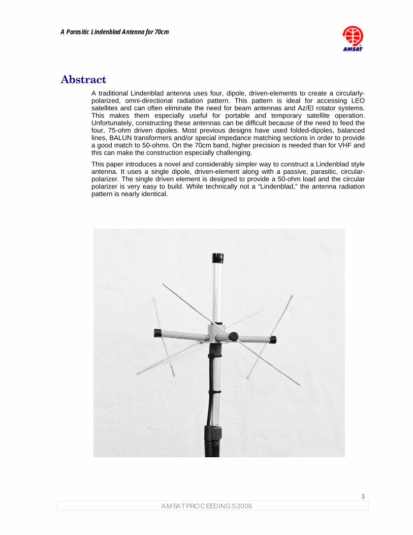
This paper introduces a novel and considerably simpler way to construct a Lindenblad style antenna. It uses a single dipole, driven-element along with a passive, parasitic, circular-polarizer. The single driven element is designed to provide a 50-ohm load and the circular polarizer is very easy to build. While technically not a “Lindenblad,” the antenna radiation pattern is nearly identical.
A Parasitic Lindenblad Antenna for 70cm
4
AMSAT PROCEEDINGS 2006
1 Introduction A Lindenblad antenna provides circular polarization and an omni directional pattern that has most of its radiation below 30 degrees of elevation. This pattern is ideal for accessing Low Earth Orbit (LEO) satellites. The omni directional pattern eliminates the complexity of azimuth/elevation rotors and their associated control systems yet the Lindenblad antenna can still provide a solid uplink or downlink signal to access most amateur LEO satellites. This makes them ideal for portable and temporary satellite operation as well as providing a good option for permanent or fixed stations as well.
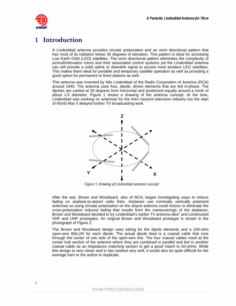
This antenna was invented by Nils Lindenblad of the Radio Corporation of America (RCA) around 1940. The antenna uses four, dipole, driven elements that are fed in-phase. The dipoles are canted at 30 degrees from horizontal and positioned equally around a circle of about λ/3 diameter. Figure 1 shows a drawing of the antenna concept. At the time, Lindenblad was working on antennas for the then nascent television industry but the start of World War II delayed further TV broadcasting work.
Figure 1. Drawing of Lindenblad antenna concept
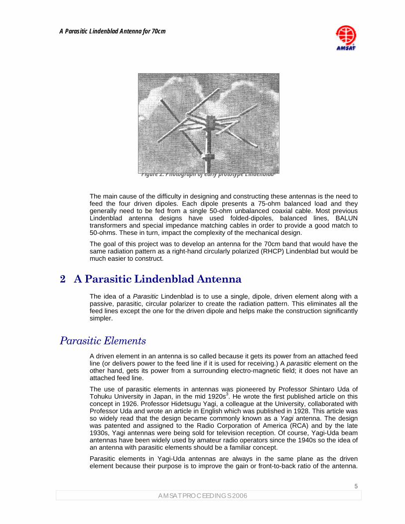
After the war, Brown and Woodward, also of RCA, began investigating ways to reduce fading on airplane-to-airport radio links. Airplanes use nominally vertically polarized antennas so using circular polarization on the airport antenna could reduce or eliminate the cross-polarization induced fading that results from the maneuverings of the airplanes. Brown and Woodward decided to try Lindenblad’s earlier TV antenna idea1 and constructed VHF and UHF prototypes. An original Brown and Woodward prototype is shown in the photograph of Figure 2.
The Brown and Woodward design uses tubing for the dipole elements and a 100-ohm open-wire BALUN for each dipole. The actual dipole feed is a coaxial cable that runs through the center of one side of the open-wire line. The four coaxial cables meet at the center hub section of the antenna where they are combined in parallel and fed to another coaxial cable as an impedance matching section to get a good match to 50-ohms. While this design is very clever and in fact worked very well, it would also be quite difficult for the average ham or the author to duplicate.
Z
XY
A Parasitic Lindenblad Antenna for 70cm
5 AMSAT PROCEEDINGS 2006
Figure 2. Photograph of early prototype Lindenblad2
The main cause of the difficulty in designing and constructing these antennas is the need to feed the four driven dipoles. Each dipole presents a 75-ohm balanced load and they generally need to be fed from a single 50-ohm unbalanced coaxial cable. Most previous Lindenblad antenna designs have used folded-dipoles, balanced lines, BALUN transformers and special impedance matching cables in order to provide a good match to 50-ohms. These in turn, impact the complexity of the mechanical design.
The goal of this project was to develop an antenna for the 70cm band that would have the same radiation pattern as a right-hand circularly polarized (RHCP) Lindenblad but would be much easier to construct.
2 A Parasitic Lindenblad Antenna The idea of a Parasitic Lindenblad is to use a single, dipole, driven element along with a passive, parasitic, circular polarizer to create the radiation pattern. This eliminates all the feed lines except the one for the driven dipole and helps make the construction significantly simpler.
Parasitic Elements A driven element in an antenna is so called because it gets its power from an attached feed line (or delivers power to the feed line if it is used for receiving.) A parasitic element on the other hand, gets its power from a surrounding electro-magnetic field; it does not have an attached feed line.
The use of parasitic elements in antennas was pioneered by Professor Shintaro Uda of Tohuku University in Japan, in the mid 1920s3. He wrote the first published article on this concept in 1926. Professor Hidetsugu Yagi, a colleague at the University, collaborated with Professor Uda and wrote an article in English which was published in 1928. This article was so widely read that the design became commonly known as a Yagi antenna. The design was patented and assigned to the Radio Corporation of America (RCA) and by the late 1930s, Yagi antennas were being sold for television reception. Of course, Yagi-Uda beam antennas have been widely used by amateur radio operators since the 1940s so the idea of an antenna with parasitic elements should be a familiar concept.
Parasitic elements in Yagi-Uda antennas are always in the same plane as the driven element because their purpose is to improve the gain or front-to-back ratio of the antenna.
A Parasitic Lindenblad Antenna for 70cm
6
AMSAT PROCEEDINGS 2006
In contrast, in the Parasitic Lindenblad, all of the antenna elements are in different planes as the purpose of the parasitic elements is to convert linear polarization to circular polarization.
Passive Circular Polarizer The Parasitic Lindenblad antenna uses a central vertical dipole as a driven element and an array of parasitic elements that make up the passive circular polarizer. The parasitic elements are arranged very much like those in a traditional Lindenblad antenna. The parasitic elements are canted at 30 degrees from horizontal and positioned equally around the center driven dipole at a spacing of 0.15 wavelengths. The parasitic elements absorb power from the electro-magnetic field of the driven element and this causes a current to flow in them.
The induced current flow in the parasitic elements causes an electro-magnetic field to be generated just as if they had been driven from a feed line. However, the current flow in each parasitic element travels along the path of the conductor, which is at 30 degrees from horizontal, rather than vertically like the driven element. This current flow distribution is exactly like the dipole currents in a traditional Lindenblad and the resulting electro-magnetic field generated from the parasitic elements is circularly polarized just like that of a Lindenblad. The circularly polarized field has both horizontal and vertical components and they are in phase-quadrature.
The overall effect is basically the sum of the radiation patterns of a traditional Lindenblad and a co-located vertical dipole with the same power applied to both. Since the power in the parasitic elements goes equally into vertical and horizontal components, the vertical field component from the parasitic elements is only one-half the magnitude of the field from the driven dipole.
The key is that the parasitic element lengths are tuned so that the current induced in them is 180-degrees out of phase with the driven dipole. This makes vertical field component from the parasitic elements cancel half the field from the driven element leaving a resulting vertical field component that is the same magnitude as if it was from a Lindenblad but of opposite polarity. The field cancellation is not perfect because the radiation pattern of the dipole is not exactly the same as the vertical pattern from the parasitic elements but, it is very close over a significant range of elevation angles.
The horizontal field from the parasitic elements is unaffected by the driven dipole because it produces no horizontal component. So, the horizontal and vertical fields from the combination of the parasitic and driven elements are virtually the same as those from a real Lindenblad except that the polarization sense is reversed. This means that we have to make the parasitic elements canted like a left-hand polarized Lindenblad to produce right-hand circular polarization.
Impedance Matching At resonance, an ordinary dipole provides a load impedance of about 75 ohms. Due to the mutual electro-magnetic coupling to the parasitic elements however, the impedance of the driven dipole in the Parasitic Lindenblad would be about 32-ohms at resonance. This 32-ohm load would not provide a good match to 50-ohm coaxial cable.
To keep construction simple, it is desirable to provide a good match without requiring additional components or folded elements. This can be done by taking advantage of the stray capacitance at the dipole feed point. This stray capacitance is about 4pF and appears in parallel with the dipole feed. By making the driven dipole a little bit longer than the resonant length, we can introduce a small amount of inductive reactance. Using this
A Parasitic Lindenblad Antenna for 70cm
7 AMSAT PROCEEDINGS 2006
inductive reactance and the stray capacitance, we can make an L-match impedance matching network and tune it to provide a good match to 50-ohms. The driven element need only be lengthened by ¾ of an inch to accomplish this so it does not affect the radiation pattern.
The vertical dipole driven element requires a balanced feed for proper operation. If the coaxial cable was just connected to the dipole, a significant antenna current would flow over the outside of the coax shield. This would negatively affect the radiation pattern and cause an impedance mismatch. Fortunately, it is very easy to make a choke BALUN by slipping a pair of inexpensive ($.56 each) ferrite cable sleeves over the outside of the coaxial cable. The coaxial cable runs down vertically from the center of the dipole and the sleeves are just aligned with the bottom of the dipole element which stops any cable radiation below the dipole.
3 Antenna Construction This antenna was designed to be easy to construct using only hand tools. Most of the construction and materials are not critical and experienced antenna builders should feel free to substitute their own favorite techniques. The few critical dimensions are noted in the text.
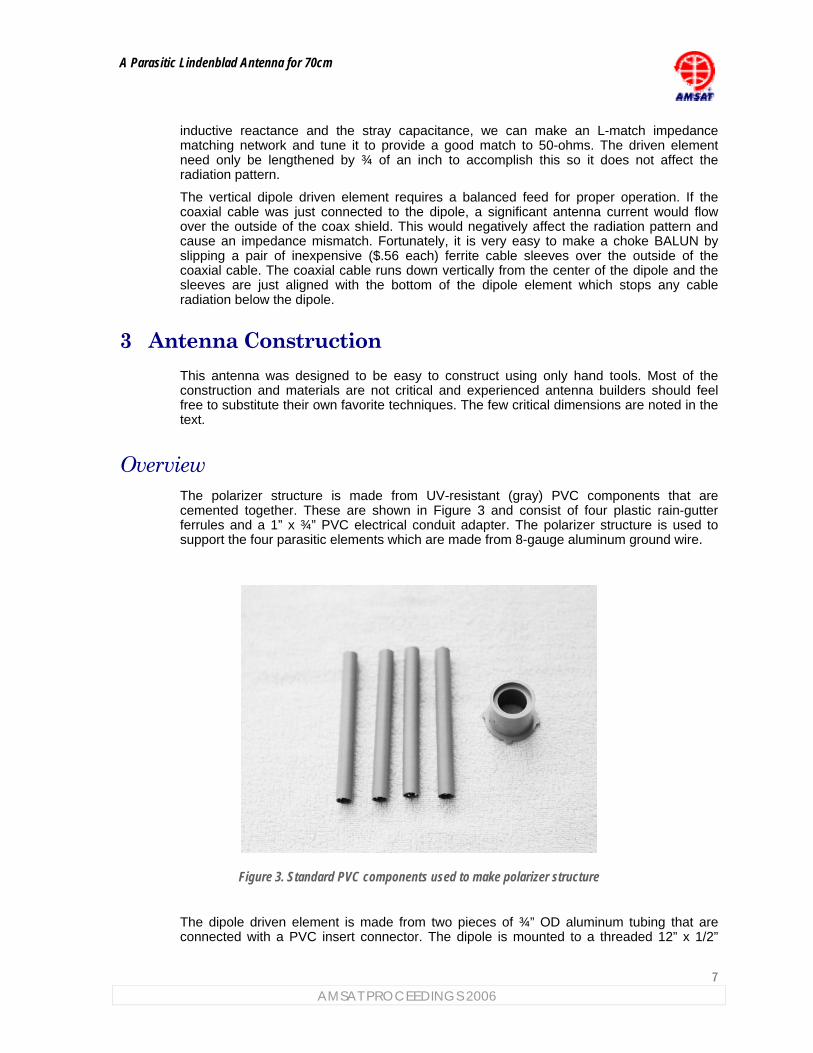
Overview The polarizer structure is made from UV-resistant (gray) PVC components that are cemented together. These are shown in Figure 3 and consist of four plastic rain-gutter ferrules and a 1” x ¾” PVC electrical conduit adapter. The polarizer structure is used to support the four parasitic elements which are made from 8-gauge aluminum ground wire.
Figure 3. Standard PVC components used to make polarizer structure
The dipole driven element is made from two pieces of ¾” OD aluminum tubing that are connected with a PVC insert connector. The dipole is mounted to a threaded 12” x 1/2”
A Parasitic Lindenblad Antenna for 70cm
8
AMSAT PROCEEDINGS 2006
PVC riser using an insert-to-threaded adapter. These PVC components are of the type used for lawn irrigation systems. The coaxial feed line is attached directly to the driven dipole using aluminum sheet metal screws.
Parts The hardware components used in this antenna were readily found in a local ACE Hardware store and most of the parts are not critical so feel free to substitute as needed. However, the aluminum tubing used for the driven dipole must be ¾” outer diameter and construction will be easier if the tubing is 17-gauge as the inner wall will be just slightly smaller than the outer wall of a PVC-insert-connector. If heaver wall tubing is used, it will be necessary to file down the PVC insert-connector to make them fit together.
Table 1. Parts list
Quantity Description
2 6-1/16” length of ¾” OD, 17-gauge, aluminum tubing
Note: Available from Texas Towers www.texastowers.com
4 11.75” lengths of #8-AWG aluminum ground wire (or 1/8” OD tubing)
1 ½” x ½” gray PVC insert connector
1 ½” to ½” gray PVC insert-to-threaded adapter
1 12” x ½” threaded gray PVC riser
4 5” x ½” gray PVC ferrule for spacing rain gutter nails
1 1” to ¾” PVC electrical conduit adapter
2 #6 x 3/8” aluminum sheet metal screw
2 #8 x ½” aluminum sheet metal screws
2 Fair-Rite cable ferrite. Part# 2643540002.
Note: Available from Mouser Electronics, www.mouser.com
Stock# 623-2643540002
1 3-foot to 10-foot length of Times Microwave LMR-240 coaxial cable
1 Male N-connector for LMR-240 coaxial cable
1 ¾” Black plastic end cap
4 ½” Black plastic end cap
Misc. Heat shrink tubing for 3/4” cable, Regular bodied gray PVC solvent cement for Carlon™ conduit,, Marine Goop™ outdoor waterproof contact adhesive, Ox-Gard™ OX-100 grease for aluminum electrical connections, black wire ties
A Parasitic Lindenblad Antenna for 70cm
9 AMSAT PROCEEDINGS 2006
The LMR-240 coaxial cable was selected because of its low-loss, low cost and wide availability but any 50-ohm small diameter cable may be used. The cable ferrites have a 0.25” inner diameter so the cable needs to be smaller than this to fit.
Assembly Start by making the parasitic element assemblies, see Figure 4. Cut the plastic ferrules to 3-3/4” length. Drill a 1/8” hole through each ferrule 3/16” from the end. The hole should go through both ferrule walls and be centered as much as possible. Push a ground wire through the hole in the ferrule and center the wire so that it sticks out the same amount on both sides of the ferrule. Apply the Marine Goop™ liberally through the end of the ferrule to coat the wire and the inside of the ferrule wall. Set these aside for several hours until the Goop™ is dry.
Figure 4. Parasitic element assembly
Next make the driven dipole assembly. Please see Figure 5. Gently tap the PVC insert connector into the two pieces of aluminum tubing with a mallet or hammer until they are spaced ¼” in the center. The overall dipole length should be 12-3/8”. Then, drill a hole for a #6 screw, 3/8” from end of the tubing at the center insulator. Directly across the insulator, also spaced 3/8” from the end, drill a hole for a #8 screw.
3 -3/4”
1/8” hole”
#8 AWG aluminum wire
3/16”
A Parasitic Lindenblad Antenna for 70cm
10
AMSAT PROCEEDINGS 2006
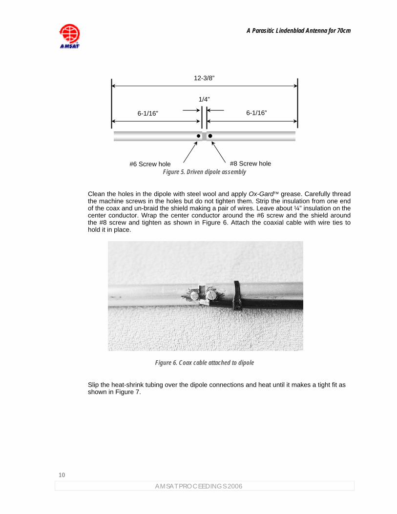
Figure 5. Driven dipole assembly
Clean the holes in the dipole with steel wool and apply Ox-Gard™ grease. Carefully thread the machine screws in the holes but do not tighten them. Strip the insulation from one end of the coax and un-braid the shield making a pair of wires. Leave about ¼” insulation on the center conductor. Wrap the center conductor around the #6 screw and the shield around the #8 screw and tighten as shown in Figure 6. Attach the coaxial cable with wire ties to hold it in place.
Figure 6. Coax cable attached to dipole
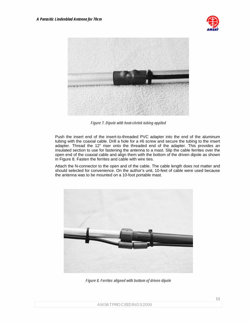
Slip the heat-shrink tubing over the dipole connections and heat until it makes a tight fit as shown in Figure 7.
6-1/16”
1/4”
12-3/8”
#8 Screw hole #6 Screw hole
6-1/16”
A Parasitic Lindenblad Antenna for 70cm
11 AMSAT PROCEEDINGS 2006
Figure 7. Dipole with heat-shrink tubing applied
Push the insert end of the insert-to-threaded PVC adapter into the end of the aluminum tubing with the coaxial cable. Drill a hole for a #6 screw and secure the tubing to the insert adapter. Thread the 12” riser onto the threaded end of the adapter. This provides an insulated section to use for fastening the antenna to a mast. Slip the cable ferrites over the open end of the coaxial cable and align them with the bottom of the driven dipole as shown in Figure 8. Fasten the ferrites and cable with wire ties.
Attach the N-connector to the open and of the cable. The cable length does not matter and should selected for convenience. On the author’s unit, 10-feet of cable were used because the antenna was to be mounted on a 10-foot portable mast.
Figure 8. Ferrites aligned with bottom of driven dipole
A Parasitic Lindenblad Antenna for 70cm
12
AMSAT PROCEEDINGS 2006
To make the parasitic element hub, drill four, ½” holes in the conduit adapter, spaced equally around the adapter with the holes flush with the top of the flange (i.e. the ¾” conduit end.) The four parasitic element assemblies will fit into these holes but do not attach them yet.
Using a file or a Dremel™ tool, create a small channel for the #6 screw at the dipole center. The parasitic element hub needs to fit over the driven dipole so that the ½” holes are centered on the PVC insulator. Create the channel so that the hub fits flat over the center part of the dipole.
After this is done, drill a hole through the top part of the hub and through the aluminum tubing for a #8 machine screw. Screw in the #8 screw to hold the hub in place.
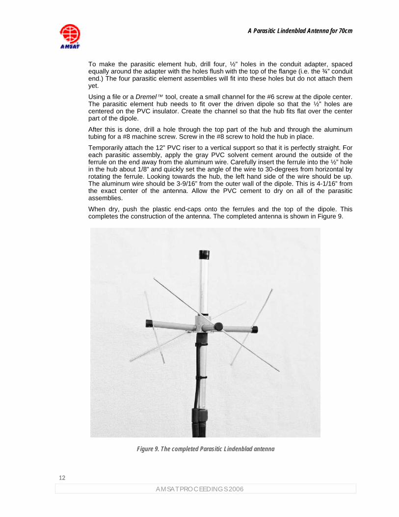
Temporarily attach the 12” PVC riser to a vertical support so that it is perfectly straight. For each parasitic assembly, apply the gray PVC solvent cement around the outside of the ferrule on the end away from the aluminum wire. Carefully insert the ferrule into the ½” hole in the hub about 1/8” and quickly set the angle of the wire to 30-degrees from horizontal by rotating the ferrule. Looking towards the hub, the left hand side of the wire should be up. The aluminum wire should be 3-9/16” from the outer wall of the dipole. This is 4-1/16” from the exact center of the antenna. Allow the PVC cement to dry on all of the parasitic assemblies.
When dry, push the plastic end-caps onto the ferrules and the top of the dipole. This completes the construction of the antenna. The completed antenna is shown in Figure 9.
Figure 9. The completed Parasitic Lindenblad antenna
A Parasitic Lindenblad Antenna for 70cm
13 AMSAT PROCEEDINGS 2006
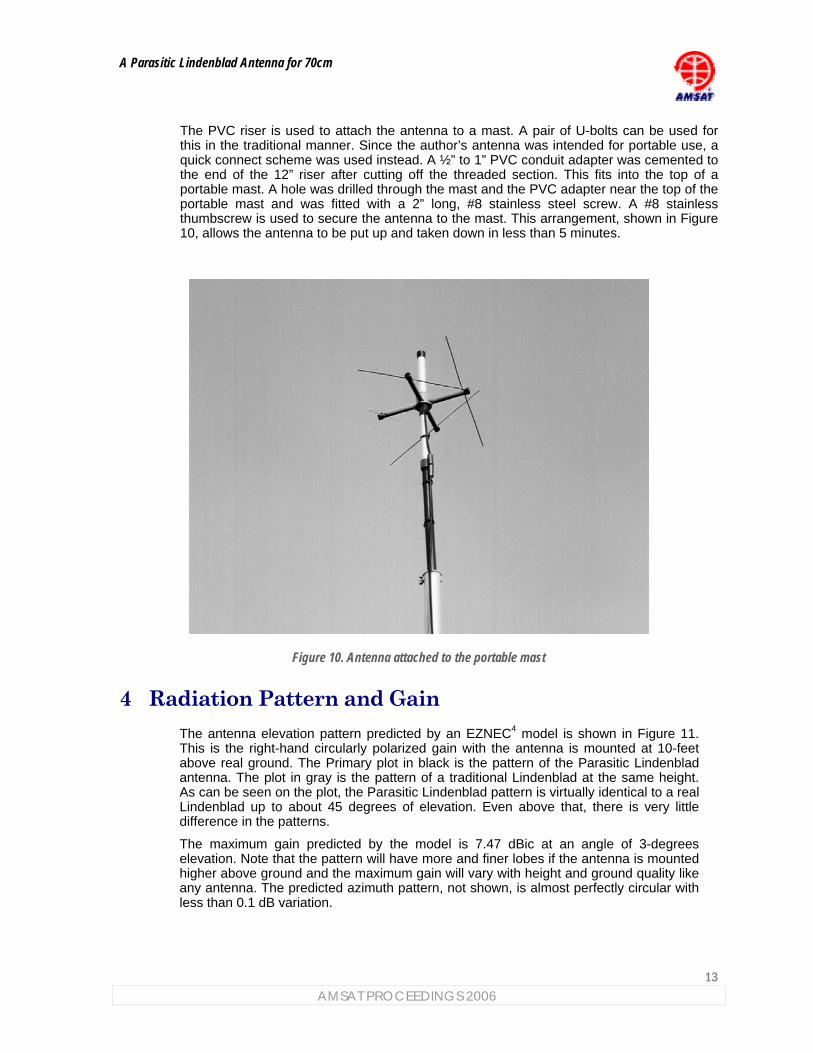
The PVC riser is used to attach the antenna to a mast. A pair of U-bolts can be used for this in the traditional manner. Since the author’s antenna was intended for portable use, a quick connect scheme was used instead. A ½” to 1” PVC conduit adapter was cemented to the end of the 12” riser after cutting off the threaded section. This fits into the top of a portable mast. A hole was drilled through the mast and the PVC adapter near the top of the portable mast and was fitted with a 2” long, #8 stainless steel screw. A #8 stainless thumbscrew is used to secure the antenna to the mast. This arrangement, shown in Figure 10, allows the antenna to be put up and taken down in less than 5 minutes.
Figure 10. Antenna attached to the portable mast
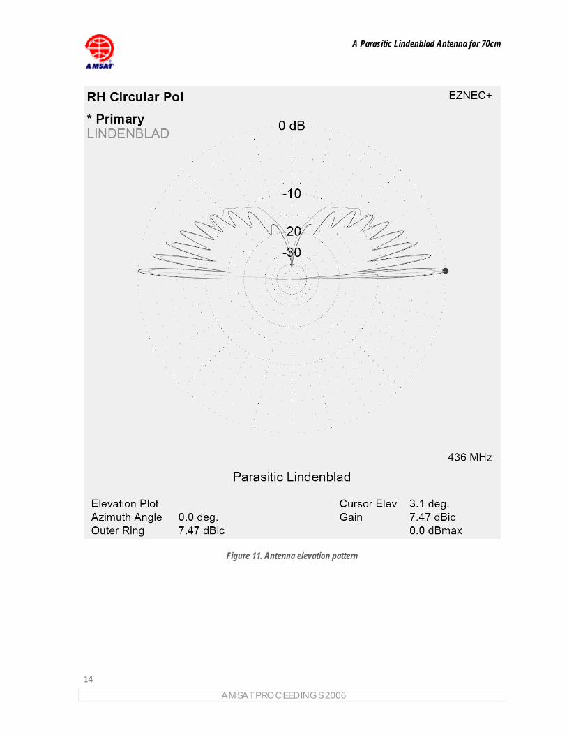
4 Radiation Pattern and Gain The antenna elevation pattern predicted by an EZNEC4 model is shown in Figure 11. This is the right-hand circularly polarized gain with the antenna is mounted at 10-feet above real ground. The Primary plot in black is the pattern of the Parasitic Lindenblad antenna. The plot in gray is the pattern of a traditional Lindenblad at the same height. As can be seen on the plot, the Parasitic Lindenblad pattern is virtually identical to a real Lindenblad up to about 45 degrees of elevation. Even above that, there is very little difference in the patterns.
The maximum gain predicted by the model is 7.47 dBic at an angle of 3-degrees elevation. Note that the pattern will have more and finer lobes if the antenna is mounted higher above ground and the maximum gain will vary with height and ground quality like any antenna. The predicted azimuth pattern, not shown, is almost perfectly circular with less than 0.1 dB variation.
A Parasitic Lindenblad Antenna for 70cm
14
AMSAT PROCEEDINGS 2006
Figure 11. Antenna elevation pattern
A Parasitic Lindenblad Antenna for 70cm
15 AMSAT PROCEEDINGS 2006
5 Testing This antenna was designed to work as assembled with no adjustments and no testing or test equipment required. However, the prototype was tested in order to verify the antenna design. These tests are not needed when constructing a copy of the antenna.
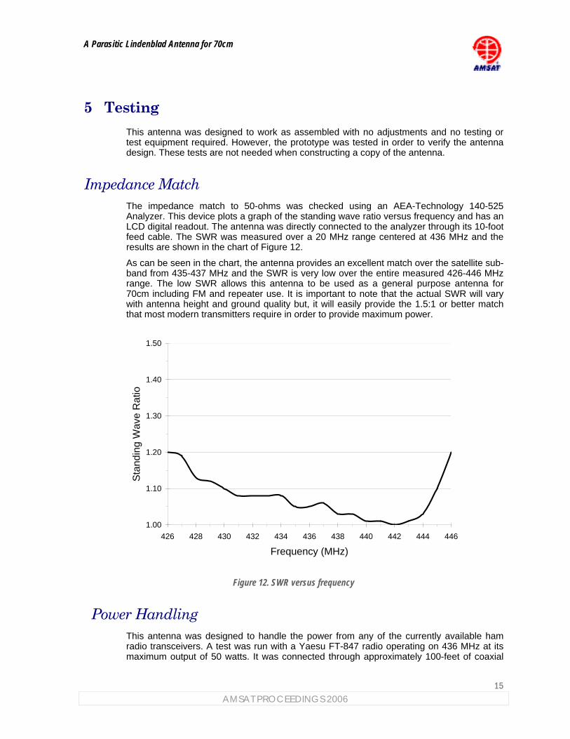
Impedance Match The impedance match to 50-ohms was checked using an AEA-Technology 140-525 Analyzer. This device plots a graph of the standing wave ratio versus frequency and has an LCD digital readout. The antenna was directly connected to the analyzer through its 10-foot feed cable. The SWR was measured over a 20 MHz range centered at 436 MHz and the results are shown in the chart of Figure 12.
As can be seen in the chart, the antenna provides an excellent match over the satellite sub-band from 435-437 MHz and the SWR is very low over the entire measured 426-446 MHz range. The low SWR allows this antenna to be used as a general purpose antenna for 70cm including FM and repeater use. It is important to note that the actual SWR will vary with antenna height and ground quality but, it will easily provide the 1.5:1 or better match that most modern transmitters require in order to provide maximum power.
1.00
1.10
1.20
1.30
1.40
1.50
426 428 430 432 434 436 438 440 442 444 446
Frequency (MHz)
Sta
ndin
g W
ave
Rat
io
Figure 12. SWR versus frequency
Power Handling This antenna was designed to handle the power from any of the currently available ham radio transceivers. A test was run with a Yaesu FT-847 radio operating on 436 MHz at its maximum output of 50 watts. It was connected through approximately 100-feet of coaxial
A Parasitic Lindenblad Antenna for 70cm
16
AMSAT PROCEEDINGS 2006
cable to the Parasitic Lindenblad antenna prototype. The power at the antenna input connector was measured using a Bird™ Thruline Wattmeter and showed about 30 watts forward power. The reflected power was much less than the first mark on the meter scale confirming the low measured SWR. The FT-847 was operated key-down to provide a continuous carrier for 9-1/2 minutes. There were no observed ill effects on the antenna although the power from the FT-847 dropped a few watts by the end of the test.
An overload test was also run using about 100 watts at the antenna via a high-power amplifier. After about 5 minutes of key-down, continuous operation, there were no observed ill effects to the antenna although the ferrites were noticeably warm.
Circularity The circularity was checked by using a phased array sense antenna that could be selected for either horizontal or vertical polarization. The sense antenna was connected to a Yaesu FT-817 radio in USB mode with the AGC switched off. The output of the FT-817 was fed to an AC voltmeter calibrated in dB. The antenna under test was set up at a height of 10-feet and approximately 100-feet from the sense antenna location. An un-modulated carrier signal at 436 MHz was fed to the antenna under test using a signal generator.
A horizontally polarized reference antenna was tested first. The sense antenna was switched from horizontal to vertical. The reference antenna showed about 15 dB difference between horizontal versus vertical polarization. The Parasitic Lindenblad antenna was tested next using the same procedure and showed no measurable difference between the horizontal and vertical polarization of the sense antenna indicating very good circularity.
6 Summary This paper has presented a design for a Parasitic Lindenblad antenna. This antenna has only a single, dipole, driven element and uses a passive, parasitic, circular polarizer to create the same radiation pattern as a Lindenblad antenna. This approach makes construction of the antenna significantly simpler.
The Parasitic Lindenblad antenna was used to make SSB and FM voice contacts via the AO-07, FO-29, SO-50, AO-51 and VO-52 satellites during a test session and on ARRL Field Day 2006. Field day is an excellent test of an antenna as it is probably the busiest time of the year on the satellites and the antenna performed well.
The Parasitic Lindenblad is omni-directional and does not require an antenna rotator system making it an ideal choice for both portable and fixed station use on LEO satellites.
Tony Monteiro, AA2TX, was first licensed in 1973 as WN2RBM and has been a member of AMSAT since 1994. He worked in the communications industry for over 25 years and was a member of the technical staff at Bell Laboratories and a senior manager at several telecommunications companies.
1 Circularly Polarized Omnidirectional Antenna, by George H. Brown and O. M. Woodward Jr., RCA Review vol. 8, no. 2, June 1947, pp. 259-269. 2 Ibid. pg 267. 3 Directive Short Wave Antenna, 1924, IEEE History Center, Rutgers University, New Brunswick, NJ, USA available at: www.ieee.org 4 EZNEC+ V4 antenna software by Roy W. Lewallen (W7EL.) Available from: www.eznec.com