Session: MAT-04, Fatigue and Fracture I Abstract ID: 2755723
1
A Peridynamics-FEM Approach for Crack Path Prediction in Fiber-Reinforced Composites
Srujan Rokkam,1 and Quang Truong2 Advanced Cooling Technologies, Inc., Lancaster, PA 17601, USA
Max Gunzburger3 Florida State University, Tallahassee, FL 32306, USA
and Kishan Goel4
Naval Air Systems Command, Patuxent River, MD 20670, USA
Peridynamics (PD) theory provides a means to investigate crack propagation behavior in solids, without the need for re-meshing the domain or other special treatments necessitated by conventional FEM approaches. As such, it has been increasing applied for modeling failure in different applications. In this work, we investigate crack propagation behavior in fiber-reinforced composite (FRC) structures using a Peridynamics approach that builds on finite element method (FEM) solution kernels. The PD bonds representative of the composite are modeled as truss elements which takes into account the corresponding fiber/matrix micromechanics in definition of its constitutive behavior. The PD-FEM framework is implemented using a commercial FEA package ABAQUS, via custom defined application programming interface (API). Subsequently, we employ it to investigate crack propagation behavior in 3D composite structures subject to various types of loading conditions. Crack propagation simulations are performed on 3-D composites with fibers oriented in different directions per ply (unidirectional fiber lay-up within each ply) and multidirectional composite (woven, multi-ply). The developed framework is able to predict crack propagation behavior based on applied loading conditions and nature of pre-existing defects. A comparison between simulated results and available literature data is also undertaken.
I. IntroductionIn recent years, development of high performance fiber reinforced composites has led to replacement of metals in
several light-weight demanding applications such as defense, aerospace and civilian infrastructure. However, damage initiation and propagation in fiber-reinforced composites under complex loading conditions are not well understood. Damage and failure in composites is a result of complex interactions between different damage mechanisms such as matrix cracking, fiber breakage, shear banding, pull out or kinking of fibers, fiber/matrix de-bonding and delamination. While some of these damage mechanisms can occur simultaneously over different length scales, they interact and inflict each other by weakening the load carrying capacity of the composite. Damage initiates at the fiber and matrix constituent level and progresses upwards through ply, laminate and structural scale of the composite. The internal damage at constituent level accumulates under continuous or cyclic loads and results in macroscopic stiffness degradation while the composite still has load-bearing capacity. Stiffness degradation in turns leads to load redistribution and progression of damage to cause ultimate catastrophic failure of the FRC structure.
Several theories have emerged to understand the response of FRC laminates at different length scale and to quantify their deformation, damage initiation, stiffness degradation and ultimate failure. They can be classified as: failure theories, micromechanics models for damage and fracture, continuum damage mechanics based models and fracture mechanics models. Failure theories like Hashin, Tsai-Hill, Tsai-Wu and Yamada-Sun [1,2,3,4] evaluate
1 Lead Engineer, Defense/Aerospace – R&D. 2 Research Engineer I, Defense/Aerospace – R&D. 3 Francis Eppes Eminent Professor, Department of Scientific Computing. 4 Structures Division, Naval Air Systems Command (NAVAIR).
Dow
nloa
ded
on
Janu
ary
29, 2
018
| http
://ar
c.ai
aa.o
rg |
DO
I: 1
0.25
14/6
.201
8-06
51
2018 AIAA/ASCE/AHS/ASC Structures, Structural Dynamics, and Materials Conference
Manuscript draft for AIAA SciTech Forum 2018 Session: MAT-04, Fatigue and Fracture I
Abstract ID: 2755723 failure in composite ply based on their stress or strain components. Micromechanics approaches evaluate the overall properties of heterogeneous material based on geometries and properties of individual phases (within a representative volume element) through a process of homogenization and evaluate the damage and failure based on local stress or strain state within the constituent phases [5,6]. In continuum damage mechanics (CDM) models, the progressive failure resulting from continuous stiffness degradation in obtained terms of damage variables characteristic of several damage processes and their evolution laws. The technique enables prediction of damage initiation, progressive and ultimate failure of composite laminates under complex loading environments [7,8]. The fracture mechanics models characterize the onset and growth of delamination using fracture criterion which are obtained based on energy balance between continuum and discrete cracks models, and energy release rate due to propagation of the crack [9,10]. Most of these theories capture the behavior of FRP composites and its constituents at a single target length scale. Some multi-scale damage models have also been developed in which damage across structural scales is hierarchically coupled to invoke lower scale damage models [11,12]. Several studies have applied these methods to study damage evolution in composites using FEM. However, owing to the numerical structure of FEM which requires re-meshing at the crack tip, these methods are limited in their ability to track crack propagation. To circumvent this limitation of mesh regeneration, models based on extended finite element method (xFEM) [13] and cohesive zone element method [14] have been developed. However, they still need kinetic relation to inject elements along crack growth path.
Peridynamics (PD) is a nonlocal continuum mechanics theory introduced by Silling [15] as a reformulation theclassical elasticity theory for modeling materials with discontinuities such as cracks. The theory replaces the partial differential equations of classical solid mechanics with integro-differential equations. The resulting numerical structure of the governing equations is amenable to crack growth, since the integral can be evaluated across discontinuities/cracks without any complicated meshing or crack-tracking algorithms.
The PD equations are based on a model which treats the internal forces within a body as a network of interactions between material points. The interaction between a pair of material points x′ and x is called a bond, which can account for the long-range interaction between particles (nonlocality). For relative position 𝝃𝝃 = x′ − x and relative displacement 𝜼𝜼 = u(x′, 𝑡𝑡 ) − u(x, 𝑡𝑡 ), f(𝜼𝜼 , 𝝃𝝃 ) describes the material behavior by mapping the deformation given by 𝜼𝜼 for a bond 𝝃𝝃 to a force density (per unit volume). Both displacement u(x, 𝑡𝑡 ) and internal forces 𝐟𝐟 ( . ) are permitted to have discontinuities or other singularities and the numerical solution of the integral equations has a meshless particle-type structure. Consequently, the PD approach has been applied to several problems like modeling fracture [16], damage analysis of composite laminates [17,18], electro-migration [19], transient heat conduction [20], thermomechanical fracture [21] and accumulated crack propagation due to fatigue loads [22]. One of the drawback of PD simulation is that it is computationally expensive because of its small time step requirement. Therefore, for elastic cases in which discontinuity is not present, it is not as efficient as the conventional Finite Element approach.
II. Finite Element based Peridynamics Models
Fig. 1. FE Truss Element based Peridynamics. (ABAQUS model)
Dow
nloa
ded
on
Janu
ary
29, 2
018
| http
://ar
c.ai
aa.o
rg |
DO
I: 1
0.25
14/6
.201
8-06
51
3
Abstract ID: 2755723 In this work, a coupled Finite Element (FE) and Peridynamics (PD) based micro-damage dependent effective
medium multiscale framework was developed. The framework describes the nature of interactions between PD material points within each lamina as a function of: (a) underlying fiber architecture (b) local damage state and (c) local content of micro-voids or porosity. A simple PD material model which is indicative of these features can be written as:
𝜌𝜌u(x, 𝑡𝑡) = � f u(η, 𝜉𝜉;𝜙𝜙𝑑𝑑)𝑑𝑑𝑑𝑑x′ + b(x, 𝑡𝑡)ℋx
(2)
where, 𝜙𝜙𝑑𝑑 is a field variable identifying the extent of micro-damage experienced by the underlying PD material point; f u has the usual definition of PD force density (per volume square) and is dependent on the local value of damage parameters 𝜙𝜙𝑑𝑑, for a pair of interacting PD material point volumes (bond 𝜉𝜉 between x and x′). The micro-damage field variable can be expanded to include influence of fatigue damage, manufacturing defects, voids etc. But here, we consider the simpler case of material weakening due to one lumped micro-damage factor.
We further assume that the material is a linear PD solid and specialize fu to be a linear function of u. To include the anisotropy resulting from heterogeneous (layered) systems like FRP composites we suppose, the PD system for a composite material with micro-damage can be represented as:
where, 𝐟𝐟 is a constitutive response for a homogeneous, isotropic material (fiber or matrix), that is dependent on the local fiber architecture (orientation of fibers, fiber lay-up, matrix to fiber ratio). We define f𝑑𝑑 as a function that capture the weakening of the PD bonds within the composite, due to contributions from material points at 𝐱𝐱 and 𝐱𝐱′. For simplicity, we chose this function f𝑑𝑑 to be a linear function of 𝜙𝜙𝑑𝑑(𝐱𝐱). It can be defined differently for each ply and for interactions between the ply and is representative of the weakening of the material due to micro-damage within the unit cell of the PD material point.
We also extend our PD material model to include such a micro-damage dependence for definition of the bond breakage based on the stretch threshold model as:
𝑠𝑠(x, x′) > 𝑠𝑠𝑜𝑜 (𝜙𝜙𝑑𝑑) (3b)
Here, 𝑠𝑠𝑜𝑜(𝜙𝜙𝑑𝑑) represents a modified stretch-degradation model, which takes into account the loss of ability of the material to stretch due to micro-damage within the interacting bond material points. Equations (2)-(3) together define a PD material model for a heterogeneous micro-elastic linear PD solid which is undergoing reduction in material stiffness due to microscale damage processes (matrix cracking, fiber matrix de-bonding etc.). More details on the micro-damage sensitive PD model and its construction are described elsewhere [23].
To reduce the computational cost of PD simulation, recent studies [24,25,26] focused on implementing PD to conventional finite element analysis (FEA) models. In Peridynamics theory, the scalar bond stretch is defined as:
𝑠𝑠 = |𝝃𝝃 + 𝜼𝜼| − |𝝃𝝃|
|𝝃𝝃|(4)
Macek and Silling [24] implemented PD into ABAQUS using truss elements to simulate a rigid spherical ball impacting ductile aluminum plate, and verified the result with Peridynamics code EMU. Killic [25] utilized sub-domain method to implement PD into Ansys to simulate a plate with circular cut out subjected to uniaxial tension. Since the basic PD equations are consistent with the fundamentals of FEA, PD bonds can be generated through FEA truss elements with appropriate stiffness properties. Furthermore, the modeling domain can be divided into sub-domains where the region expected to failure is modeled using PD, the remainder of the domain is modeled in FEA framework, and the overlap region contains FE elements with small modulus properties, embedded with PD elements, as shown in Fig. 1.
Such bond stretch is similar to the engineering strain in FE truss element. Hence, PD bonds can be implemented as truss element by setting fracture strain equal to the critical stretch, 𝑠𝑠0. In another word, the strain of truss element is set to zero when it is equal or larger than the pre-defined critical stretch to simulate a broken bond. The algorithm for PD bond as FE truss element is shown below in Table 1.
Dow
nloa
ded
on
Janu
ary
29, 2
018
| http
://ar
c.ai
aa.o
rg |
DO
I: 1
0.25
14/6
.201
8-06
51
4
Table 1: Algorithm for FE truss element based PD: – Determine the initial angle of the bonds.– Apply additional variable svar (initially = 1), representing condition of the bonds.
• If svar = 0 then strain = 0• Else then calculate strain for FE truss element
– Apply stiffness properties according to the initial angles.– Solve bond force from strain and stiffness.– Calculate the new length of the bond/truss
• If the new length reaches critical stretch, then svar = 0 (bond break).• Else, svar = 1
III. Implementation of the PD framework into ABAQUS-CAE
The PD framework is implemented into the commercial software ABAQUS through user element (VUEL) and external database (VexternalDB) subroutines. The framework employs Smoothed Particle Hydrodynamics (SPH) kernel to generate neighbor list, and Explicit Finite Element kernel to solve the bond force between each pair of particles. The framework also utilizes effective modulus tensors superimposed with a spatially random correlation to account for discontinuities in material properties, representing defects due to manufacturing, as well as utilizes the micro-modulus functions dependent on damage variables to account for material degradation due to cumulative micro-scale damage from continuous and cyclic loading.
Fig. 2. Neighbor list from ABAQUS SPH. Center node on the left in blue box, neighbor nodes on the right in red box.
Fig. 3. PD bonds (green) between two nodes (red) in ABAQUS.
The ABAQUS SPH kernel provides the neighbor list of each node. As shown in Fig. 2, in each row, the first number represents the center node and the following numbers represents its neighboring nodes. From there, the bonds between the center node and its neighboring nodes are automatically generated using a simple script. As shown in Fig. 3, the bonds are the green lines connecting all material nodes (red dots).
Dow
nloa
ded
on
Janu
ary
29, 2
018
| http
://ar
c.ai
aa.o
rg |
DO
I: 1
0.25
14/6
.201
8-06
51
5
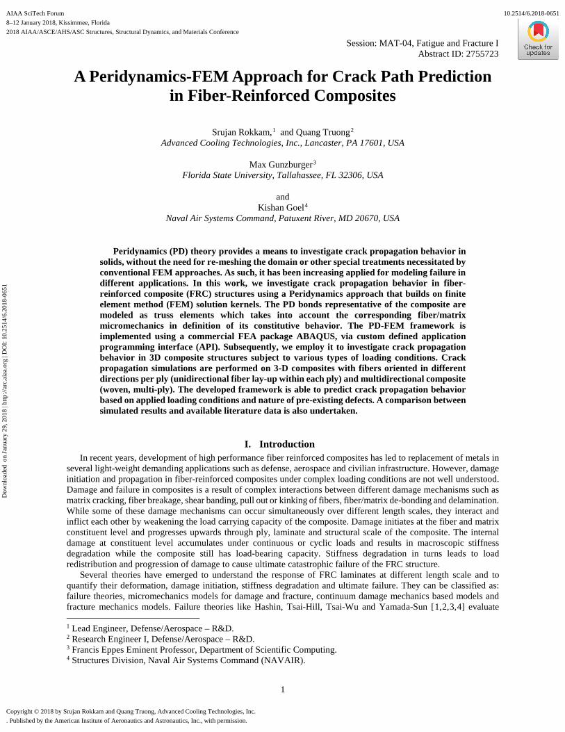
Fig. 4. (a) Sample 3-D Solidworks model of a rotor blade, (b) 3-D notched rotor blade with mesh 4-node tetrahedral FE elements (two sides) with PD elements (center).
Due to robustness of ABAQUS software and SPH neighbor list generator, complex structure from other CAD software could be imported and meshed. Fig. 4(a) presents a sample of a rotor blade created in Solidworks. The rotor blade is meshed in PD particles coupled with FE elements effortlessly, as shown in Fig. 4(b). The pre-existing crack in the center of the blade can be created by deleting the respected PD nodes. The overlap region include both PD and FE elements, where FE elements have a small value to elastic modulus to reduce the stiffness.
IV. Numerical Simulations
Here we demonstrate the capabilities of the developed FE based PD framework through 3-D simulations of FRC thin plate. Case studies include crack propagation in: uni-directional fiber orientation FRC, multi-directional fiber orientation FRC, FRC with pre-existing defects, multi-ply FRC, and FRC with complex geometries.
A. Crack Propagation in Uni-directional FRC
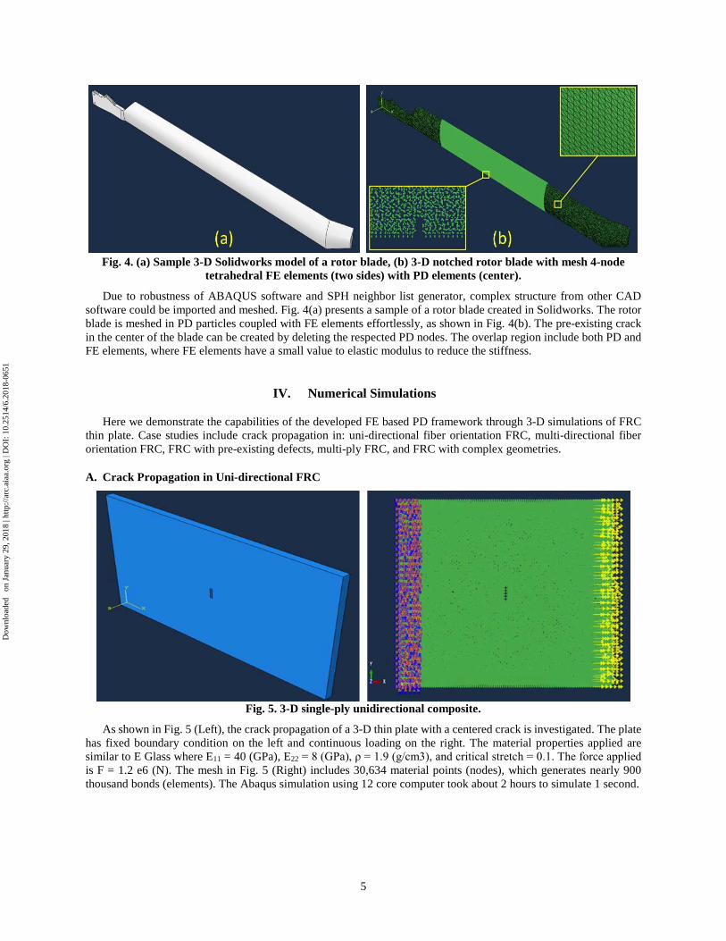
Fig. 5. 3-D single-ply unidirectional composite.
As shown in Fig. 5 (Left), the crack propagation of a 3-D thin plate with a centered crack is investigated. The plate has fixed boundary condition on the left and continuous loading on the right. The material properties applied are similar to E Glass where E11 = 40 (GPa), E22 = 8 (GPa), ρ = 1.9 (g/cm3), and critical stretch = 0.1. The force applied is F = 1.2 e6 (N). The mesh in Fig. 5 (Right) includes 30,634 material points (nodes), which generates nearly 900 thousand bonds (elements). The Abaqus simulation using 12 core computer took about 2 hours to simulate 1 second.
Dow
nloa
ded
on
Janu
ary
29, 2
018
| http
://ar
c.ai
aa.o
rg |
DO
I: 1
0.25
14/6
.201
8-06
51
6
Fig. 6. Crack propagation of 0° fiber orientation at (a) time t = 0.25 s, (b) time t = 0.4 s.
Fig. 7. Crack propagation of 0° fiber orientation at time (a) t = 0 s, (b) t = 0.4 s. (FE and PD coupling)
First, the plate is applied with a single ply unidirectional composite with horizontal (0°) fiber orientation. As shown in Fig. 6, the centered crack starts propagating in vertical direction when the applied force is parallel to the fiber orientation of a unidirectional lamina. Similarly, the FRC with horizontal fiber orientation is simulated with coupling between FE and PD framework. The plate is divided into FE region (green color), PD region (red color), and overlap region (both color), as shown in Fig. 7. The crack propagation is similar to that of Fig. 6; however, the computational cost is greatly reduced due to much less elements to solve.
Fig. 8. (a) (b) 3-D simulation by ACT, (c) 2-D simulation by Hu [27], (d) 2-D simulation by Killic [25].
Dow
nloa
ded
on
Janu
ary
29, 2
018
| http
://ar
c.ai
aa.o
rg |
DO
I: 1
0.25
14/6
.201
8-06
51
7
Abstract ID: 2755723 Next, the plate is applied with a single ply unidirectional composite with diagonal (45°) fiber orientation. The
material properties applied are E11 = 329 (GPa), E22 = 6 (GPa), ρ = 1.63 (g/cm3), and critical stretch = 0.1. We verify our 3-D simulation result with the 2-D results available from Killic [25] and Hu [27] in term of damage map, which is computed by dividing the number of broken bonds by number of all bonds connecting to that node. The damage map is from 0 (no damage, blue color) to 1 (fully damage, in red). As shown in Fig. 8, the crack propagation paths from our model (in a and b) are very similar to those from Killic [25] and Hu [27] (in c and d). However, we experienced additional crack from two sides of the plate, which might be a more realistic propagation in 45° lamina.
B. Crack Propagation in Multi-directional FRC
Fig. 9. 0°/90° cross-ply woven composite: (a) previous PD model, (b) current FE based PD model.
The thin plate with centered crack (used previously in section A) is applied with a 0°/90° cross-ply woven composite. The crack propagates initially in diagonal direction, then in time changes direction toward vertical. The damage map of the current FE-PD model matches well with ACT’s existing PD model developed under a previous Navy Phase I SBIR program for PD modeling of thick composite [28].
C. Crack Propagation in Multi-Ply Laminate FRCIn the case of five-ply laminate FRC, the plate shown in Fig. 5 is increased in thickness and applied five different
angles of fiber orientation, 0°/45°/90°/-45°/0°. The mesh created includes 66,240 material points (nodes), generating nearly 1.42 million bonds (elements). Due to ABAQUS’ robust user subroutine kernel, five different user elements (VU1, VU2, VU3, VU4, and VU5) with each angle is identified in only one user element subroutine (VUEL).
Fig. 10. Crack Propagation of Five-ply laminate with fiber orientation of 0°/45°/90°/-45°/0°, (Left) 2-D and (Right) 3-D view. Each ply is presented by each color (blue, yellow, green, red, and black).
Fig. 10 shows the displacement of PD nodes in each ply, colored respectively in blue, yellow, green, red, and black. From the center crack, each ply propagates in different crack path. Furthermore, the top and bottom ply (in blue and black) are both at 0° orientation; however, they propagate differently. That is because one ply is connected to 45° ply, while the other is connected to -45° ply. This difference demonstrates the inter-ply effect in or FE based PD model.
Dow
nloa
ded
on
Janu
ary
29, 2
018
| http
://ar
c.ai
aa.o
rg |
DO
I: 1
0.25
14/6
.201
8-06
51
8
D. Crack Propagation in FRC with Pre-Existing Material Defect
Fig. 11. 3D notched plate with pre-existing material defect under continuous loading.
To demonstrate the effect of pre-existing material defect, the sample in this case is a thin plate with a notched crack on the left side, and a sub-region on the right side with 10% to 30% broken bonds distributed randomly, as shown in Fig. 11. The plate is under continuous loading on both side. The material properties applied are similar to E Glass, and the composite structure is 0°/90° cross-ply woven.
Fig. 12. Damage map comparison between: (a), (b), (c) non-defected plate, and (d), (e), (f) 10% defected plate. (a), (d) time t = 0 s. (b), (e) time t = 0.1 s. (c), (f) time t = 0.5 s
Dow
nloa
ded
on
Janu
ary
29, 2
018
| http
://ar
c.ai
aa.o
rg |
DO
I: 1
0.25
14/6
.201
8-06
51
9
Abstract ID: 2755723 Fig. 12 shows the comparison in crack propagation between a normal plate on the left (a,b,c), and a defected plate
on the right (d,e,f). The first row represents initial time t = 0 s, the second row represents time t = 0.1 s, and the last row represents time t = 0.5 s. As stated above, the damage is from 0 (no damage, blue color) to 1 (fully damage, in red). In the normal plate, the crack propagates from the notch diagonally, then vertically, and diagonally again at the end. At t = 0.5 s, the normal plate experiences a new crack on the right side. In Fig. 12(d), the initial damage is shown on the right side of the plate in lighter blue color. The initial defect not only changes the path of the main crack from the notch but also generates additional cracks in the center.
E. Crack Propagation in FRC with Complex GeometriesThe sample of a rotor blade, shown in Fig. 4(a), is used in this case. The rotor blade is created in Solidworks as a
STEP file. Again, the material properties applied are similar to E Glass, and the composite structure is 0°/90° cross-ply woven. The blade is under fixed condition at the root and continuous drag loading at the tip of trailing edge. A pre-existing crack is initialized at the center of leading edge, as shown in Fig. 13. The mesh created includes 337,407 material points (nodes), generating nearly 8.53 million PD bonds (elements).
Fig. 13. PD mesh of a rotor blade with pre-existing notch and continuous drag.
Fig. 14 shows the deformation and crack propagation of a notched rotor blade under continuous drag loading. As the drag begins to bend the rotor blade, the initial crack propagates as a result. The crack path is in a diagonal and vertical path, similar to that of a woven composite structure in Fig. 12(c).
Fig. 14.Crack propagation in a notched rotor blade.
Dow
nloa
ded
on
Janu
ary
29, 2
018
| http
://ar
c.ai
aa.o
rg |
DO
I: 1
0.25
14/6
.201
8-06
51
10
V. ConclusionsIn recent years, development of high performance fiber reinforced composites has led to replacement of metals in
several light-weight demanding applications such as defense, aerospace and civilian infrastructure. However, damage initiation and propagation in fiber-reinforced composites under complex loading conditions are not well understood. There is a need for a non-local modeling framework to provide insight into crack growth in fiber-reinforced composite materials.
In this work, a coupled Finite Element (FE) and Peridynamics (PD) based multi-scale framework was developed which can accurately predict 3-D crack propagation paths of fiber-reinforced composite structures. The PD framework has the capability to estimate effective modulus of complex FRC structure as well as to account for material defect from manufacturing, and material degradation from continuous loadings. The PD framework is implemented into ABAQUS software through user subroutines with two different approaches: FE based, and SPH based. The robustness of ABAQUS kernel assist our developed model in setup simulation cases effortlessly. In addition, coupling between FE and PD framework can be performed to enhance the model efficiency. The developed FE based PD model was compared against other literature studies (Killic [25], Hu [27]), and a previous study at ACT’s on damage of thick FRC. The results of FE based PD model not only shows similarities with other results, but also provides a more realistic 3-D crack pattern.
VI. AcknowledgmentsThis work was funded by the U.S. Naval Air Warfare Center (NAVAIR), through a Small Business Innovation
Research (SBIR) program, Contract No. N68335-16-C-0301, awarded to Advanced Cooling Technologies, Inc. (ACT) located in Lancaster, PA. Dr. Max Gunzburger, participated as sub-contractor on this program. The authors would like to thanks the valuable support and discussions from NAVAIR technical monitors: Dr. Kishan Goel and Dr. Nam Phan. The authors would also like to thank Dr. Victor Oancea of Dassault Systemes Simulia Corp (DS), Providence, RI, for participating in advisory role and guiding the ACT team on implementation aspects of particle methods. This work benefited from the Partner Agreement DS Ref. 02431-2016, between ACT and Dassault Systemes Simulia Corp.
VII. References
[1] Tsai S.W., Wu E.M., “A General Theory of Strength for Anisotropic Materials,” Journal of Composite Materials, vol. 5, issue1, pp. 58-80, 1971.
[2] Hashin Z., “Failure Criteria for Unidirectional Fiber Composites,” Journal of Applied Mechanics, Vol. 47, 329-334, 1980.[3] Kaw A. K, Mechanics of Composite Materials, CRC Press, 2nd ed., 2005.[4] Yamada S. E., Sun C. T, “Analysis of laminate strength and its distribution,” Journal of Composite Materials, 12, 275-284,
1978.[5] Nemat-Nasser S., M. Hori, Micromechanics: Overall Properties of Heterogeneous Materials, Elsevier, 2nd ed., 1999.[6] Mahishi J.M, Engineering Fracture Mechanics, 25(2), 197-228, 1986.[7] Schuecker C. and Pettermann H.E., Archives of Computational Methods in Engineering, Springer, 15, 163-184, 2008.[8] Liu P.F. and Zheng J.Y., Material and Design, Vol. 31, 3825-3834, 2010.[9] McCartney L.N., “Mechanics of matrix cracking in brittle-matrix fibre-reinforced composites,” Proceeding of the Royal
Society A: Mathematical, Physical and Engineering Sciences, 409, 329-350, 1987.[10] Friedrich K., Application of Fracture Mechanics to Composite Materials, Elsevier, 1990.[11] Soutis C and Beaumont P., Multiscale modeling of composite material systems, Woodhead Publishing, 2005.[12] Aboudi J et al., Micromechanics of composite Materials, Butterworth-Heinemann, 2013.[13] Fries T. P., Baydoun M., “Crack propagation criteria in three dimensions using the XFEM and an explicit–implicit crack
description,” International Journal of Fracture, 89, 1527-1558, 2012.[14] Zhang, P., Klein, P., et al., “Numerical simulation of cohesive fracture by the virtual-internal-bond model,” Computer
Modeling in Engineering and Sciences, Vol. 3, 263-277, 2002.[15] Silling S. A., “Reformulation of elasticity theory for discontinuities and long-range forces,” Journal of the
Mechanics and Physics of Solids, 48:175–209, 2000.[16] Silling S.A., Askari E., “A Meshfree Method Based on the PD Model of Solid Mechanics,” Comp. Struct., 83, 2005[17] Xu J, Askari A, Weckner O, and Silling S., “Peridynamic Analysis of Impact Damage in Composite Laminates,” Journal of
Aerospace Engineering, Vol 21, Issue 3, July 2008.[18] Askari, E, Xu J, Silling S, “Peridynamic analysis of damage and failure in composites,” 44th AIAA Aerospace Sciences
Meeting and Exhibit, Reno, Nevada, AIAA-2006-88, 2006.[19] Read D.T. and Tewary V. K., “Modeling electromigration using the peridynamics approach,” Woodhead Publishing Series
in Electronic and Optical Materials, pg. 45-69, 2011.
[20] Bobaru, F and Duangpanya, M, “The peridynamic formulation for transient heat conduction,” International Journal of Heatand Mass Transfer, 53, 4047-4059, 2010
[21] Agwai, A., et al., “A new thermomechanical fracture analysis approach for 3D integration technology,” ElectronicComponents and Technology Conference, 740-745, 2011.
[22] Oterkus E., Guven I., and Madenci E., “Fatigue failure model with peridynamic theory,” IEEE Conference, 1-6, 2010.[23] Truong Q., Rokkam S., Gunzburger M., “Physics-based Toolkit for Progressive Damage Prediction in
Composites”, NAVAIR Phase I SBIR Final Report, Contract N68335-16-C-0301, Distribution B, Dec 2016.[24] R. W. Macek and S. A. Silling, “Peridynamics via finite element analysis,” Finite Elements in Analysis and Design, 43:15,
1169–1178, 2007.[25] Kilic, B., & Madenci, E., “Coupling of peridynamic theory and the finite element method,” Journal of Mechanics of
Materials and Structures, 5(5), 707-733, 2010.[26] Lall, P.,Shantaram, S., Panchagade, D., “Peridynamic-models using finite elements for shock and vibration reliability of lead
free electronics,” Thermal and Thermomechanical Phenomena in Electronic Systems, 12th IEEE Intersociety Conference, pp.1-12, 2010.
[27] Hu W., Ha Y. D., Bobaru F., “Peridynamic model for dynamic fracture in unidirectional fiber-reinforced composites,”Computer Methods in Applied Mechanics and Engineering, 217-220, 247-261, 2012.
[28] Rokkam S., Desai T., and Gunzburger M., Peridynamic modeling of multiscale damage and failure in thickcomposites, NAVAIR SBIR Phase I Final Report, Contract N68335-13-C-0405, Distribution B, March 2014.