A PERSPECTIVE ON SCIENCE AND TECHNOLGY OF FAST BREEDER REACTORS - A manuscript specially prepared for those students of Science & Technology who are inquisitive about Nuclear Energy BALDEV RAJ Distinguished Schientist, and Director, Indira Gandhi Centre for Atomic Research, Kalpakkam I feel delighted to take the opportunity provided by the Chennai Science City. I would be speaking to you on the salient aspects of nuclear energy in India, specifically, the fast breeder reactors. I dedicate this manuscript to Dr. Raja Ramanna. He was among the great scientific visionaries who nurtured excellence in the Indian nuclear energy programme. Dr. Ramanna was born on January 28,1925, in Karnataka. He took his Ph.D. in London, was specialised in nuclear physics, neutron physics, and reactor design, and had contributed to the theory of nuclear fission. He led the team that carried out the first nuclear test in Pokhran in 1974. He held many distinguished positions such as, Director of BARC (for over a decade), Director-general, DRDO, Chairman, Atomic Energy Commission, Scientific adviser to the defence minister, Union minister of state for defence, Member of Rajya Sabha, and so on. He was a recepient of Padma Shri, Padma Bhushan & Padma Vibhushan awards. He had a passion for music and was a Licentiate of Royal School of Music (London). He died on September 23, 2004. Nuclear science and technology in India owes greatly to Dr. Ramanna’s contributions. Dr. Raja Ramanna nurtured the growth of the Indira Gandhi Centre for Atomic Research, in its formative years, and was always keen to contribute to the activities of the Centre. In today’s talk, the following major topics are covered: • Physics concepts to understand nuclear energy and breeding. • Notable reactors around the world. • Milestones achieved at IGCAR. • Comparison of energy sources – Advantage nuclear! • Fast reactor vs. Thermal reactor. • Indian scenario. • Engineering considerations in fast reactor design. • Structural materials. FISSION OF AN ATOMIC NUCLEUS It is well known that atom is made up of a central positively charged nucleus surrounded by negatively charged electrons. The nucleus consists of nucleons (i.e. protons, neutrons). Within the nuclear range (10 -12 cm), called a short-range, the nucleons attract each other with a force, much larger than the electrostatic repulsion between the positively charged protons. Within this range, the closer they are, the stronger their bond is. On the other hand, the long-range repulsive electrostatic forces that exist between all the protons in the nucleus continuously tend to force the
Transcript
A PERSPECTIVE ON SCIENCE AND TECHNOLGY OF FAST BREEDER REACTORS
Distinguished Schientist, and Director, Indira Gandhi Centre for Atomic Research, Kalpakkam
I feel delighted to take the opportunity provided by the Chennai Science City. I would be speaking to you on the salient aspects of nuclear energy in India, specifically, the fast breeder reactors. I dedicate this manuscript to Dr. Raja Ramanna. He was among the great scientific visionaries who nurtured excellence in the Indian nuclear energy programme. Dr. Ramanna was born on January 28,1925, in Karnataka. He took his Ph.D. in London, was specialised in nuclear physics, neutron physics, and reactor design, and had contributed to the theory of nuclear fission. He led the team that carried out the first nuclear test in Pokhran in 1974. He held many distinguished positions such as, Director of BARC (for over a decade), Director-general, DRDO, Chairman, Atomic Energy Commission, Scientific adviser to the defence minister, Union minister of state for defence, Member of Rajya Sabha, and so on. He was a recepient of Padma Shri, Padma Bhushan & Padma Vibhushan awards. He had a passion for music and was a Licentiate of Royal School of Music (London). He died on September 23, 2004. Nuclear science and technology in India owes greatly to Dr. Ramanna’s contributions. Dr. Raja Ramanna nurtured the growth of the Indira Gandhi Centre for Atomic Research, in its formative years, and was always keen to contribute to the activities of the Centre. In today’s talk, the following major topics are covered:
• Physics concepts to understand nuclear energy and breeding. • Notable reactors around the world. • Milestones achieved at IGCAR. • Comparison of energy sources – Advantage nuclear! • Fast reactor vs. Thermal reactor. • Indian scenario. • Engineering considerations in fast reactor design. • Structural materials.
FISSION OF AN ATOMIC NUCLEUS It is well known that atom is made up of a central positively charged nucleus surrounded by negatively charged electrons. The nucleus consists of nucleons (i.e. protons, neutrons). Within the nuclear range (10-12 cm), called a short-range, the nucleons attract each other with a force, much larger than the electrostatic repulsion between the positively charged protons. Within this range, the closer they are, the stronger their bond is. On the other hand, the long-range repulsive electrostatic forces that exist between all the protons in the nucleus continuously tend to force the
protons apart, thus tending to split the nucleus. An increase in the neutron-to-proton ratio only partially compensates for the growing proton-proton repulsive force in the heavy nuclides. Thus, the stability of a nucleus depends on the balance between the attractive nuclear force and the repulsive electrostatic force. If the latter is higher than the former, the nucleus splits, i.e. fissions. The heaviest variety of nuclei (like uranium) are delicately balanced and require only a small energy addition for fission. A distortion in the heavy nucleus leading to fission, is commonly achieved by adding a neutron into the nucleus. However, some nuclei experience chances of undergoing fission, even without adding a neutron, such a phenomenon called ‘Spontaneous fission’. Where does the fission energy come from? Einstein has established that energy and mass are related, through the equation: energy = mass × speed of light2. Stability of a nucleus needs the right amount of energy. Excess energy leads to instability and must be released. In nuclear reactions, mass converts to energy and vice-versa. When U-235 fissions into two pieces (smaller nuclei), the pieces are more stable than U-235. Thus the release of large energy in fissioning a heavy nucleus, like U-235, is a process towards reaching a configuration of higher stability. The excess energy released is equal to a reduction in the net mass. We will see a little more about the energy that holds the nucleons together. [The unit of energy often chosen in nuclear physics is an electron-volt (eV). 1 eV = 1.602×10⁻¹⁹ Joules.]
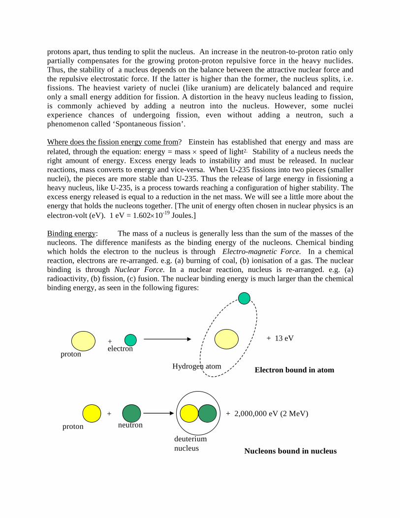
Binding energy: The mass of a nucleus is generally less than the sum of the masses of the nucleons. The difference manifests as the binding energy of the nucleons. Chemical binding which holds the electron to the nucleus is through Electro-magnetic Force. In a chemical reaction, electrons are re-arranged. e.g. (a) burning of coal, (b) ionisation of a gas. The nuclear binding is through Nuclear Force. In a nuclear reaction, nucleus is re-arranged. e.g. (a) radioactivity, (b) fission, (c) fusion. The nuclear binding energy is much larger than the chemical binding energy, as seen in the following figures:
+ 13 eV
proton electron
Hydrogen atom
+
Electron bound in atom
+ 2,000,000 eV (2 MeV) proton neutron
deuterium nucleus
+
Nucleons bound in nucleus
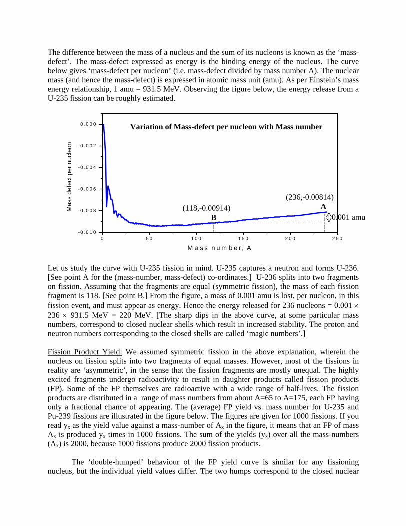
The difference between the mass of a nucleus and the sum of its nucleons is known as the ‘mass-defect’. The mass-defect expressed as energy is the binding energy of the nucleus. The curve below gives ‘mass-defect per nucleon’ (i.e. mass-defect divided by mass number A). The nuclear mass (and hence the mass-defect) is expressed in atomic mass unit (amu). As per Einstein’s mass energy relationship, 1 amu = 931.5 MeV. Observing the figure below, the energy release from a U-235 fission can be roughly estimated.
0 5 0 1 0 0 1 5 0 2 0 0 2 5 0-0 .0 1 0
-0 .0 0 8
-0 .0 0 6
-0 .0 0 4
-0 .0 0 2
0 .0 0 0
Mas
s de
fect
per
nuc
leon
M a s s n u m b e r , A
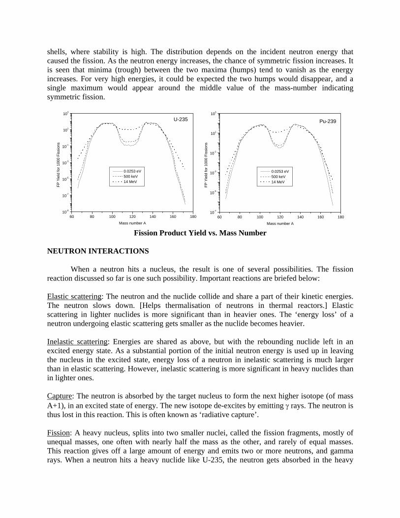
Let us study the curve with U-235 fission in mind. U-235 captures a neutron and forms U-236. [See point A for the (mass-number, mass-defect) co-ordinates.] U-236 splits into two fragments on fission. Assuming that the fragments are equal (symmetric fission), the mass of each fission fragment is 118. [See point B.] From the figure, a mass of 0.001 amu is lost, per nucleon, in this fission event, and must appear as energy. Hence the energy released for 236 nucleons = 0.001 × 236 × 931.5 MeV = 220 MeV. [The sharp dips in the above curve, at some particular mass numbers, correspond to closed nuclear shells which result in increased stability. The proton and neutron numbers corresponding to the closed shells are called ‘magic numbers’.] Fission Product Yield: We assumed symmetric fission in the above explanation, wherein the nucleus on fission splits into two fragments of equal masses. However, most of the fissions in reality are ‘asymmetric’, in the sense that the fission fragments are mostly unequal. The highly excited fragments undergo radioactivity to result in daughter products called fission products (FP). Some of the FP themselves are radioactive with a wide range of half-lives. The fission products are distributed in a range of mass numbers from about A=65 to A=175, each FP having only a fractional chance of appearing. The (average) FP yield vs. mass number for U-235 and Pu-239 fissions are illustrated in the figure below. The figures are given for 1000 fissions. If you read yx as the yield value against a mass-number of Ax in the figure, it means that an FP of mass Ax is produced yx times in 1000 fissions. The sum of the yields (yx) over all the mass-numbers (Ax) is 2000, because 1000 fissions produce 2000 fission products. The ‘double-humped’ behaviour of the FP yield curve is similar for any fissioning nucleus, but the individual yield values differ. The two humps correspond to the closed nuclear
(236,-0.00814) A (118,-0.00914)
B 0.001 amu
Variation of Mass-defect per nucleon with Mass number
shells, where stability is high. The distribution depends on the incident neutron energy that caused the fission. As the neutron energy increases, the chance of symmetric fission increases. It is seen that minima (trough) between the two maxima (humps) tend to vanish as the energy increases. For very high energies, it could be expected the two humps would disappear, and a single maximum would appear around the middle value of the mass-number indicating symmetric fission.
Fission Product Yield vs. Mass Number
NEUTRON INTERACTIONS
When a neutron hits a nucleus, the result is one of several possibilities. The fission reaction discussed so far is one such possibility. Important reactions are briefed below:
Elastic scattering: The neutron and the nuclide collide and share a part of their kinetic energies. The neutron slows down. [Helps thermalisation of neutrons in thermal reactors.] Elastic scattering in lighter nuclides is more significant than in heavier ones. The ‘energy loss’ of a neutron undergoing elastic scattering gets smaller as the nuclide becomes heavier.
Inelastic scattering: Energies are shared as above, but with the rebounding nuclide left in an excited energy state. As a substantial portion of the initial neutron energy is used up in leaving the nucleus in the excited state, energy loss of a neutron in inelastic scattering is much larger than in elastic scattering. However, inelastic scattering is more significant in heavy nuclides than in lighter ones.
Capture: The neutron is absorbed by the target nucleus to form the next higher isotope (of mass A+1), in an excited state of energy. The new isotope de-excites by emitting γ rays. The neutron is thus lost in this reaction. This is often known as ‘radiative capture’.
Fission: A heavy nucleus, splits into two smaller nuclei, called the fission fragments, mostly of unequal masses, one often with nearly half the mass as the other, and rarely of equal masses. This reaction gives off a large amount of energy and emits two or more neutrons, and gamma rays. When a neutron hits a heavy nuclide like U-235, the neutron gets absorbed in the heavy
60 80 100 120 140 160 18010-9
10-7
10-5
10-3
10-1
101
103
U-235
Mass number A
FP Y
ield
for 1
000
Fiss
ions
0.0253 eV 500 keV 14 MeV
60 80 100 120 140 160 18010-7
10-5
10-3
10-1
101
103
Pu-239
Mass number A
FP Y
ield
for 1
000
Fiss
ions
0.0253 eV 500 keV 14 MeV
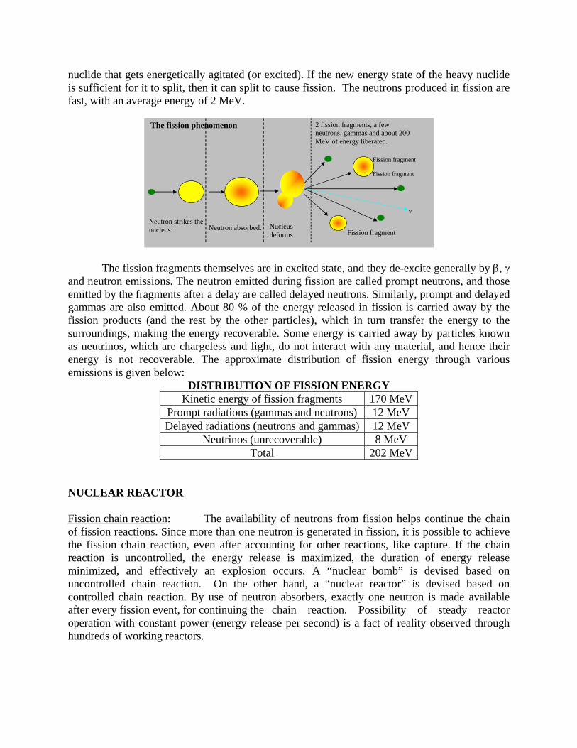
nuclide that gets energetically agitated (or excited). If the new energy state of the heavy nuclide is sufficient for it to split, then it can split to cause fission. The neutrons produced in fission are fast, with an average energy of 2 MeV.
The fission fragments themselves are in excited state, and they de-excite generally by β, γ
and neutron emissions. The neutron emitted during fission are called prompt neutrons, and those emitted by the fragments after a delay are called delayed neutrons. Similarly, prompt and delayed gammas are also emitted. About 80 % of the energy released in fission is carried away by the fission products (and the rest by the other particles), which in turn transfer the energy to the surroundings, making the energy recoverable. Some energy is carried away by particles known as neutrinos, which are chargeless and light, do not interact with any material, and hence their energy is not recoverable. The approximate distribution of fission energy through various emissions is given below:
DISTRIBUTION OF FISSION ENERGY Kinetic energy of fission fragments 170 MeV
Prompt radiations (gammas and neutrons) 12 MeV Delayed radiations (neutrons and gammas) 12 MeV
Neutrinos (unrecoverable) 8 MeV Total 202 MeV
NUCLEAR REACTOR Fission chain reaction: The availability of neutrons from fission helps continue the chain of fission reactions. Since more than one neutron is generated in fission, it is possible to achieve the fission chain reaction, even after accounting for other reactions, like capture. If the chain reaction is uncontrolled, the energy release is maximized, the duration of energy release minimized, and effectively an explosion occurs. A “nuclear bomb” is devised based on uncontrolled chain reaction. On the other hand, a “nuclear reactor” is devised based on controlled chain reaction. By use of neutron absorbers, exactly one neutron is made available after every fission event, for continuing the chain reaction. Possibility of steady reactor operation with constant power (energy release per second) is a fact of reality observed through hundreds of working reactors.
Neutron strikes the nucleus. Neutron absorbed.
Fission fragment
Fission fragment
Fission fragment
2 fission fragments, a few neutrons, gammas and about 200 MeV of energy liberated.
γ
Nucleus deforms
The fission phenomenon
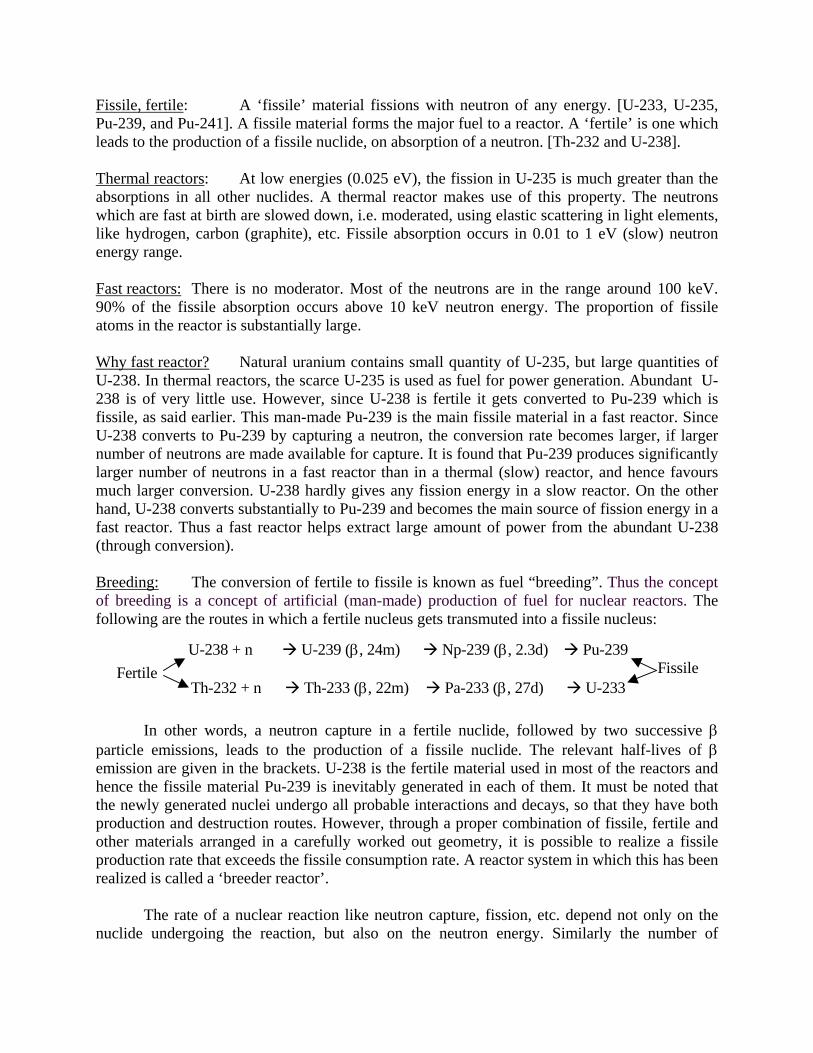
Fissile, fertile: A ‘fissile’ material fissions with neutron of any energy. [U-233, U-235, Pu-239, and Pu-241]. A fissile material forms the major fuel to a reactor. A ‘fertile’ is one which leads to the production of a fissile nuclide, on absorption of a neutron. [Th-232 and U-238]. Thermal reactors: At low energies (0.025 eV), the fission in U-235 is much greater than the absorptions in all other nuclides. A thermal reactor makes use of this property. The neutrons which are fast at birth are slowed down, i.e. moderated, using elastic scattering in light elements, like hydrogen, carbon (graphite), etc. Fissile absorption occurs in 0.01 to 1 eV (slow) neutron energy range. Fast reactors: There is no moderator. Most of the neutrons are in the range around 100 keV. 90% of the fissile absorption occurs above 10 keV neutron energy. The proportion of fissile atoms in the reactor is substantially large. Why fast reactor? Natural uranium contains small quantity of U-235, but large quantities of U-238. In thermal reactors, the scarce U-235 is used as fuel for power generation. Abundant U-238 is of very little use. However, since U-238 is fertile it gets converted to Pu-239 which is fissile, as said earlier. This man-made Pu-239 is the main fissile material in a fast reactor. Since U-238 converts to Pu-239 by capturing a neutron, the conversion rate becomes larger, if larger number of neutrons are made available for capture. It is found that Pu-239 produces significantly larger number of neutrons in a fast reactor than in a thermal (slow) reactor, and hence favours much larger conversion. U-238 hardly gives any fission energy in a slow reactor. On the other hand, U-238 converts substantially to Pu-239 and becomes the main source of fission energy in a fast reactor. Thus a fast reactor helps extract large amount of power from the abundant U-238 (through conversion). Breeding: The conversion of fertile to fissile is known as fuel “breeding”. Thus the concept of breeding is a concept of artificial (man-made) production of fuel for nuclear reactors. The following are the routes in which a fertile nucleus gets transmuted into a fissile nucleus:
U-238 + n U-239 (β, 24m) Np-239 (β, 2.3d) Pu-239
Th-232 + n Th-233 (β, 22m) Pa-233 (β, 27d) U-233
Fertile Fissile
In other words, a neutron capture in a fertile nuclide, followed by two successive β particle emissions, leads to the production of a fissile nuclide. The relevant half-lives of β emission are given in the brackets. U-238 is the fertile material used in most of the reactors and hence the fissile material Pu-239 is inevitably generated in each of them. It must be noted that the newly generated nuclei undergo all probable interactions and decays, so that they have both production and destruction routes. However, through a proper combination of fissile, fertile and other materials arranged in a carefully worked out geometry, it is possible to realize a fissile production rate that exceeds the fissile consumption rate. A reactor system in which this has been realized is called a ‘breeder reactor’. The rate of a nuclear reaction like neutron capture, fission, etc. depend not only on the nuclide undergoing the reaction, but also on the neutron energy. Similarly the number of
10-3 10-1 101 103 105 1070
1
2
3
4
5 Pu-239 U-233 U-235
η
Energy (eV)
10-2 100 102 104 106 108
0
1
2
3
4
5
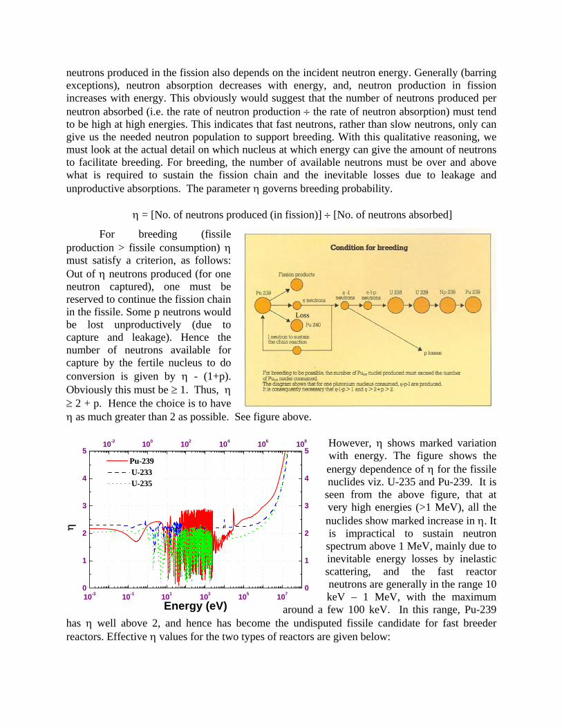
neutrons produced in the fission also depends on the incident neutron energy. Generally (barring exceptions), neutron absorption decreases with energy, and, neutron production in fission increases with energy. This obviously would suggest that the number of neutrons produced per neutron absorbed (i.e. the rate of neutron production ÷ the rate of neutron absorption) must tend to be high at high energies. This indicates that fast neutrons, rather than slow neutrons, only can give us the needed neutron population to support breeding. With this qualitative reasoning, we must look at the actual detail on which nucleus at which energy can give the amount of neutrons to facilitate breeding. For breeding, the number of available neutrons must be over and above what is required to sustain the fission chain and the inevitable losses due to leakage and unproductive absorptions. The parameter η governs breeding probability.
η = [No. of neutrons produced (in fission)] ÷ [No. of neutrons absorbed]
For breeding (fissile production > fissile consumption) η must satisfy a criterion, as follows: Out of η neutrons produced (for one neutron captured), one must be reserved to continue the fission chain in the fissile. Some p neutrons would be lost unproductively (due to capture and leakage). Hence the number of neutrons available for capture by the fertile nucleus to do conversion is given by η - (1+p). Obviously this must be ≥ 1. Thus, η ≥ 2 + p. Hence the choice is to have η as much greater than 2 as possible. See figure above.
However, η shows marked variation with energy. The figure shows the energy dependence of η for the fissile nuclides viz. U-235 and Pu-239. It is
seen from the above figure, that at very high energies (>1 MeV), all the nuclides show marked increase in η. It is impractical to sustain neutron spectrum above 1 MeV, mainly due to inevitable energy losses by inelastic scattering, and the fast reactor neutrons are generally in the range 10 keV – 1 MeV, with the maximum
around a few 100 keV. In this range, Pu-239 has η well above 2, and hence has become the undisputed fissile candidate for fast breeder reactors. Effective η values for the two types of reactors are given below:
Loss
η VALUES Pu-239 U-235 U-233 Light-water (thermal) reactor 2.04 2.06 2.26 Fast breeder reactor (Oxide fuelled). 2.45 2.10 2.31
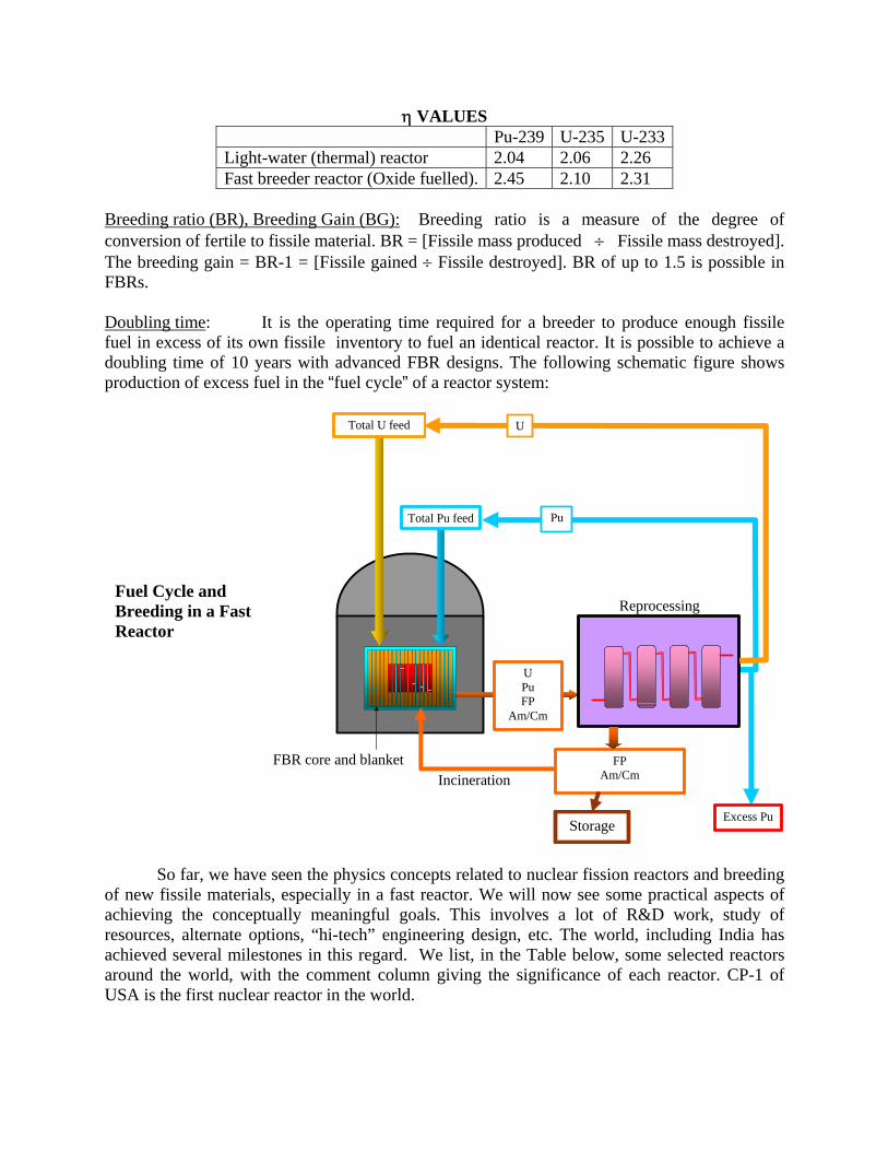
Breeding ratio (BR), Breeding Gain (BG): Breeding ratio is a measure of the degree of conversion of fertile to fissile material. BR = [Fissile mass produced ÷ Fissile mass destroyed]. The breeding gain = BR-1 = [Fissile gained ÷ Fissile destroyed]. BR of up to 1.5 is possible in FBRs. Doubling time: It is the operating time required for a breeder to produce enough fissile fuel in excess of its own fissile inventory to fuel an identical reactor. It is possible to achieve a doubling time of 10 years with advanced FBR designs. The following schematic figure shows production of excess fuel in the “fuel cycle” of a reactor system:
Excess Pu
Reprocessing
FP Am/Cm
U
Pu
U Pu FP
Am/Cm
Total Pu feed
FBR core and blanket
Total U feed
Incineration
Storage
So far, we have seen the physics concepts related to nuclear fission reactors and breeding
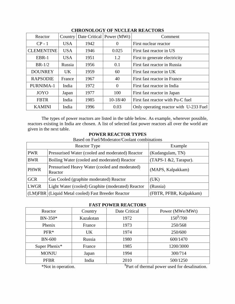
of new fissile materials, especially in a fast reactor. We will now see some practical aspects of achieving the conceptually meaningful goals. This involves a lot of R&D work, study of resources, alternate options, “hi-tech” engineering design, etc. The world, including India has achieved several milestones in this regard. We list, in the Table below, some selected reactors around the world, with the comment column giving the significance of each reactor. CP-1 of USA is the first nuclear reactor in the world.
Fuel Cycle and Breeding in a Fast Reactor
CHRONOLOGY OF NUCLEAR REACTORS Reactor Country Date Critical Power (MWt) Comment CP - 1 USA 1942 0 First nuclear reactor
CLEMENTINE USA 1946 0.025 First fast reactor in US EBR-1 USA 1951 1.2 First to generate electricity BR-1/2 Russia 1956 0.1 First fast reactor in Russia
DOUNREY UK 1959 60 First fast reactor in UK RAPSODIE France 1967 40 First fast reactor in France
PURNIMA-1 India 1972 0 First fast reactor in India JOYO Japan 1977 100 First fast reactor in Japan FBTR India 1985 10-18/40 First fast reactor with Pu-C fuel
KAMINI India 1996 0.03 Only operating reactor with U-233 Fuel The types of power reactors are listed in the table below. As example, wherever possible, reactors existing in India are chosen. A list of selected fast power reactors all over the world are given in the next table.
POWER REACTOR TYPES Based on Fuel/Moderator/Coolant combinations Reactor Type Example
PWR Pressurised Water (cooled and moderated) Reactor (Kudangulam, TN) BWR Boiling Water (cooled and moderated) Reactor (TAPS-1 &2, Tarapur).
PHWR Pressurised Heavy Water (cooled and moderated) Reactor (MAPS, Kalpakkam)
GCR Gas Cooled (graphite moderated) Reactor (UK) LWGR Light Water (cooled) Graphite (moderated) Reactor (Russia) (LM)FBR (Liquid Metal cooled) Fast Breeder Reactor (FBTR, PFBR, Kalpakkam)
FAST POWER REACTORS
Reactor Country Date Critical Power (MWe/MWt) BN-350* Kazakstan 1972 150$/700 Phenix France 1973 250/568 PFR* UK 1974 250/600
BN-600 Russia 1980 600/1470 Super Phenix* France 1985 1200/3000
MONJU Japan 1994 300/714 PFBR India 2010 500/1250
*Not in operation. $Part of thermal power used for desalination.
The milestones crossed at Kalpakkam are given below.
IGCAR MILESTONES 1971 Centre established (as Reactor Research Centre) 1985 FBTR attained first criticality 1991 FBTR power level raised to 1 MWt 1993 FBTR power level raised to 10.5 MWt & sustained 1996 FBTR fuel crosses 25,000 MWd/t burnup 1996 Post Irradiation Examination of FBTR fuel 1996 KAMINI attained criticality 1997 KAMINI taken to full power 1999 FBTR fuel reaches 50,000 MWd/t burnup 2000 Boron enrichment plant commissioned 2002 FBTR fuel reaches 1,00,000 MWd/t burnup 2003 Reprocessing mini-plant commissioned 2003 Financial sanction for PFBR. BHAVINI established. 2004 PFBR construction launched by Prime Minister.
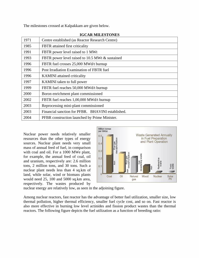
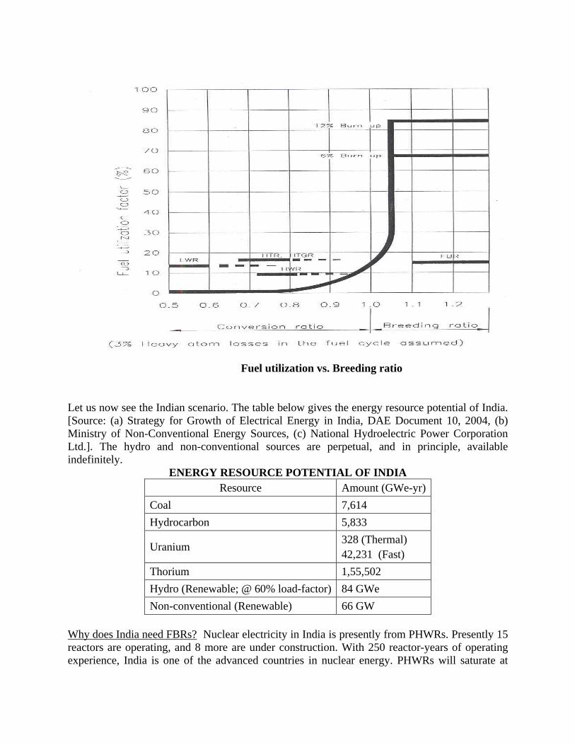
Nuclear power needs relatively smaller resources than the other types of energy sources. Nuclear plant needs very small mass of annual feed of fuel, in comparison with coal and oil. For a 1000 MWe plant, for example, the annual feed of coal, oil and uranium, respectively are: 2.6 million tons, 2 million tons, and 30 tons. Such a nuclear plant needs less than 4 sq.km of land, while solar, wind or biomass plants would need 25, 100 and 5000 sq.km area, respectively. The wastes produced by nuclear energy are relatively low, as seen in the adjoining figure. Among nuclear reactors, fast reactor has the advantage of better fuel utilization, smaller size, low thermal pollution, higher thermal efficiency, smaller fuel cycle cost, and so on. Fast reactor is also more effective in burning low level actinides and fission product wastes than the thermal reactors. The following figure depicts the fuel utilization as a function of breeding ratio:
Let us now see the Indian scenario. The table below gives the energy resource potential of India. [Source: (a) Strategy for Growth of Electrical Energy in India, DAE Document 10, 2004, (b) Ministry of Non-Conventional Energy Sources, (c) National Hydroelectric Power Corporation Ltd.]. The hydro and non-conventional sources are perpetual, and in principle, available indefinitely.
ENERGY RESOURCE POTENTIAL OF INDIA Resource Amount (GWe-yr)
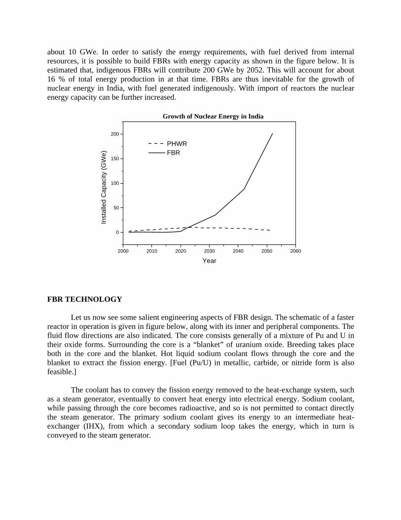
Why does India need FBRs? Nuclear electricity in India is presently from PHWRs. Presently 15 reactors are operating, and 8 more are under construction. With 250 reactor-years of operating experience, India is one of the advanced countries in nuclear energy. PHWRs will saturate at
Fuel utilization vs. Breeding ratio
about 10 GWe. In order to satisfy the energy requirements, with fuel derived from internal resources, it is possible to build FBRs with energy capacity as shown in the figure below. It is estimated that, indigenous FBRs will contribute 200 GWe by 2052. This will account for about 16 % of total energy production in at that time. FBRs are thus inevitable for the growth of nuclear energy in India, with fuel generated indigenously. With import of reactors the nuclear energy capacity can be further increased.
2000 2010 2020 2030 2040 2050 2060
0
50
100
150
200
PHWR FBR
Inst
alle
d C
apac
ity (G
We)
Year
Growth of Nuclear Energy in India
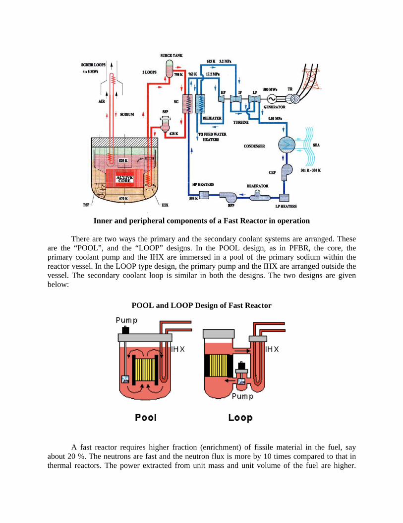
FBR TECHNOLOGY Let us now see some salient engineering aspects of FBR design. The schematic of a faster reactor in operation is given in figure below, along with its inner and peripheral components. The fluid flow directions are also indicated. The core consists generally of a mixture of Pu and U in their oxide forms. Surrounding the core is a “blanket” of uranium oxide. Breeding takes place both in the core and the blanket. Hot liquid sodium coolant flows through the core and the blanket to extract the fission energy. [Fuel (Pu/U) in metallic, carbide, or nitride form is also feasible.] The coolant has to convey the fission energy removed to the heat-exchange system, such as a steam generator, eventually to convert heat energy into electrical energy. Sodium coolant, while passing through the core becomes radioactive, and so is not permitted to contact directly the steam generator. The primary sodium coolant gives its energy to an intermediate heat-exchanger (IHX), from which a secondary sodium loop takes the energy, which in turn is conveyed to the steam generator.
Inner and peripheral components of a Fast Reactor in operation
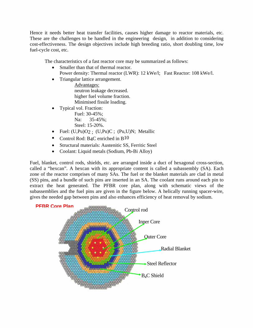
There are two ways the primary and the secondary coolant systems are arranged. These
are the “POOL”, and the “LOOP” designs. In the POOL design, as in PFBR, the core, the primary coolant pump and the IHX are immersed in a pool of the primary sodium within the reactor vessel. In the LOOP type design, the primary pump and the IHX are arranged outside the vessel. The secondary coolant loop is similar in both the designs. The two designs are given below:
POOL and LOOP Design of Fast Reactor
A fast reactor requires higher fraction (enrichment) of fissile material in the fuel, say about 20 %. The neutrons are fast and the neutron flux is more by 10 times compared to that in thermal reactors. The power extracted from unit mass and unit volume of the fuel are higher.
Hence it needs better heat transfer facilities, causes higher damage to reactor materials, etc. These are the challenges to be handled in the engineering design, in addition to considering cost-effectiveness. The design objectives include high breeding ratio, short doubling time, low fuel-cycle cost, etc.
The characteristics of a fast reactor core may be summarized as follows: • Smaller than that of thermal reactor.
Power density: Thermal reactor (LWR): 12 kWe/l; Fast Reactor: 108 kWe/l. • Triangular lattice arrangement.
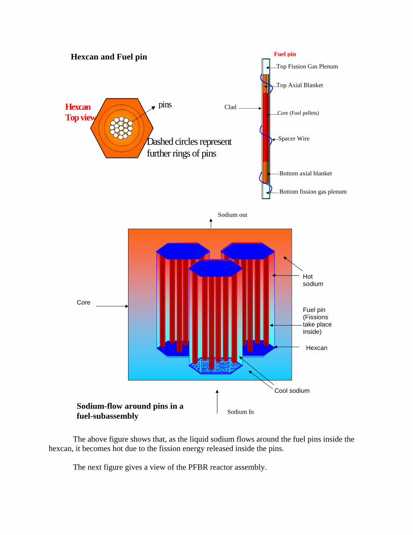
Fuel, blanket, control rods, shields, etc. are arranged inside a duct of hexagonal cross-section, called a “hexcan”. A hexcan with its appropriate content is called a subassembly (SA). Each zone of the reactor comprises of many SAs. The fuel or the blanket materials are clad in metal (SS) pins, and a bundle of such pins are inserted in an SA. The coolant runs around each pin to extract the heat generated. The PFBR core plan, along with schematic views of the subassemblies and the fuel pins are given in the figure below. A helically running spacer-wire, gives the needed gap between pins and also enhances efficiency of heat removal by sodium.
Inner Core
Radial Blanket
Control rod
Outer Core
Steel Reflector
B4C Shield
PFBR Core Plan
pins
Dashed circles represent further rings of pins
Hexcan Top view
Bottom fission gas plenum
Bottom axial blanket
Spacer Wire
Core (Fuel pellets)
Top Axial Blanket
Top Fission Gas Plenum
Clad
Fuel pin Hexcan and Fuel pin
Hot sodium
Hexcan
Cool sodium
Fuel pin (Fissions take place inside)
Core
Sodium In
Sodium out
Sodium-flow around pins in a fuel-subassembly
The above figure shows that, as the liquid sodium flows around the fuel pins inside the hexcan, it becomes hot due to the fission energy released inside the pins.
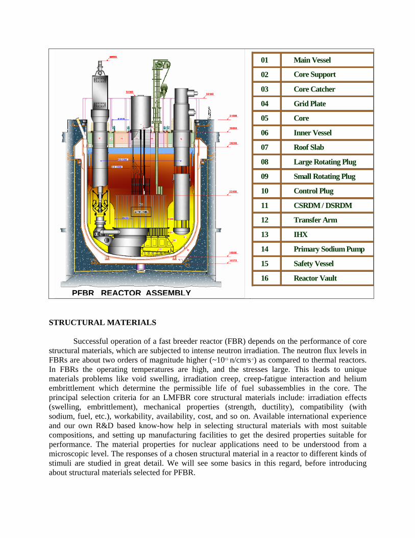
The next figure gives a view of the PFBR reactor assembly.
Successful operation of a fast breeder reactor (FBR) depends on the performance of core structural materials, which are subjected to intense neutron irradiation. The neutron flux levels in FBRs are about two orders of magnitude higher (~1015 n/cm2s-1) as compared to thermal reactors. In FBRs the operating temperatures are high, and the stresses large. This leads to unique materials problems like void swelling, irradiation creep, creep-fatigue interaction and helium embrittlement which determine the permissible life of fuel subassemblies in the core. The principal selection criteria for an LMFBR core structural materials include: irradiation effects (swelling, embrittlement), mechanical properties (strength, ductility), compatibility (with sodium, fuel, etc.), workability, availability, cost, and so on. Available international experience and our own R&D based know-how help in selecting structural materials with most suitable compositions, and setting up manufacturing facilities to get the desired properties suitable for performance. The material properties for nuclear applications need to be understood from a microscopic level. The responses of a chosen structural material in a reactor to different kinds of stimuli are studied in great detail. We will see some basics in this regard, before introducing about structural materials selected for PFBR.
PFBR REACTOR ASSEMBLY
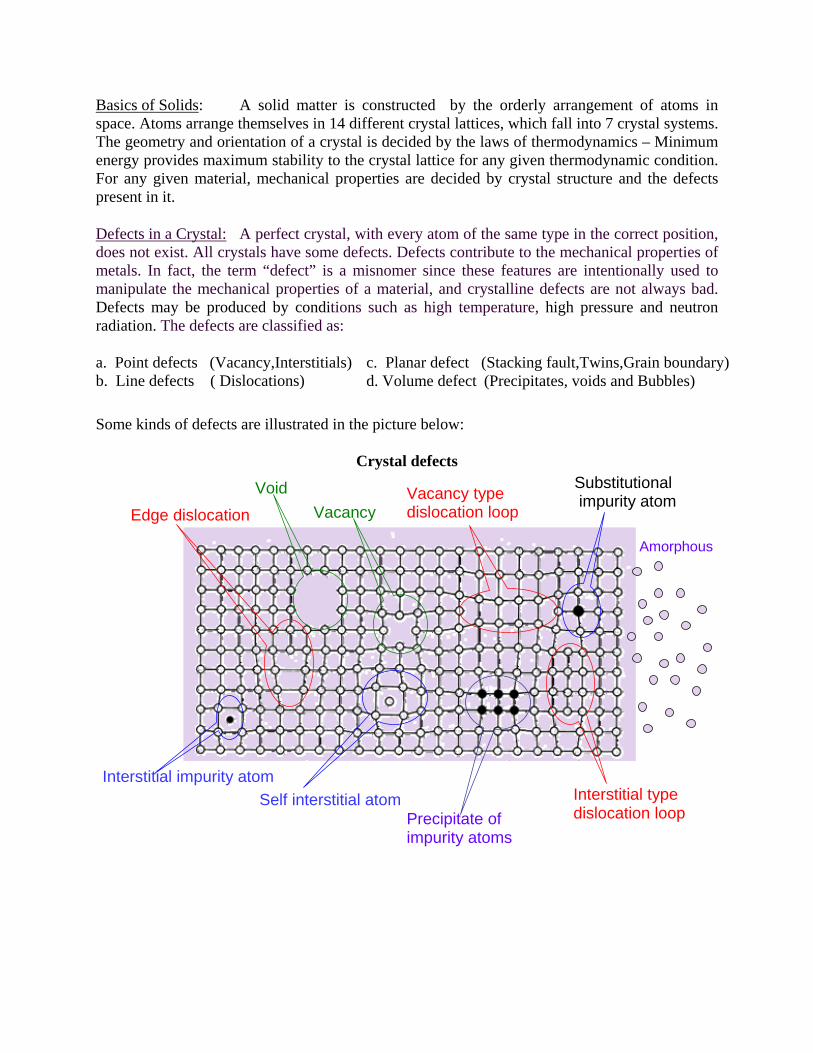
Basics of Solids: A solid matter is constructed by the orderly arrangement of atoms in space. Atoms arrange themselves in 14 different crystal lattices, which fall into 7 crystal systems. The geometry and orientation of a crystal is decided by the laws of thermodynamics – Minimum energy provides maximum stability to the crystal lattice for any given thermodynamic condition. For any given material, mechanical properties are decided by crystal structure and the defects present in it.
Defects in a Crystal: A perfect crystal, with every atom of the same type in the correct position, does not exist. All crystals have some defects. Defects contribute to the mechanical properties of metals. In fact, the term “defect” is a misnomer since these features are intentionally used to manipulate the mechanical properties of a material, and crystalline defects are not always bad. Defects may be produced by conditions such as high temperature, high pressure and neutron radiation. The defects are classified as:
a. Point defects (Vacancy,Interstitials) b. Line defects ( Dislocations)
c. Planar defect (Stacking fault,Twins,Grain boundary) d. Volume defect (Precipitates, voids and Bubbles)
Some kinds of defects are illustrated in the picture below:
Crystal defects
Interstitial impurity atom
Edge dislocation
Vacancy
Self interstitial atom
Precipitate of impurity atoms
Vacancy type dislocation loop
Interstitial type dislocation loop
Substitutional impurity atom
Amorphous
Void
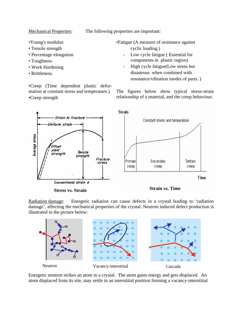
Mechanical Properties: The following properties are important: •Young's modulus • Tensile strength • Percentage elongation • Toughness • Work Hardening • Brittleness. •Creep (Time dependent plastic defor-mation at constant stress and temperature.) •Creep strength
•Fatigue (A measure of resistance against cyclic loading.)
- Low cycle fatigue ( Essential for components in plastic region)
- High cycle fatigue(Low stress but disastrous when combined with resonance/vibration modes of parts. ) The figures below show typical stress-strain relationship of a material, and the creep behaviour.
Stress vs. Strain
Strain vs. Time
Radiation damage: Energetic radiation can cause defects in a crystal leading to ‘radiation damage’, affecting the mechanical properties of the crystal. Neutron induced defect production is illustrated in the picture below:
Neutron Vacancy-interstitial Cascade Energetic neutron strikes an atom in a crystal. The atom gains energy and gets displaced. An atom displaced from its site, may settle in an interstitial position forming a vacancy-interstitial
pair. The displaced atom can knock other atoms leading to a cascade of displacements. Thus an initial displacement leads to a series of subsequent displacements causing crystal defects, hence damage. A neutron may cause multiple displacements.
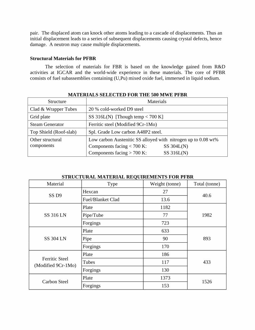
Structural Materials for PFBR The selection of materials for FBR is based on the knowledge gained from R&D activities at IGCAR and the world-wide experience in these materials. The core of PFBR consists of fuel subassemblies containing (U,Pu) mixed oxide fuel, immersed in liquid sodium.
MATERIALS SELECTED FOR THE 500 MWE PFBR Structure Materials
Low carbon Austenitic SS alloyed with nitrogen up to 0.08 wt% Components facing < 700 K: SS 304L(N) Components facing > 700 K: SS 316L(N)
STRUCTURAL MATERIAL REQUIREMENTS FOR PFBR Material Type Weight (tonne) Total (tonne)
Hexcan 27 SS D9
Fuel/Blanket Clad 13.6 40.6
Plate 1182 Pipe/Tube 77 SS 316 LN Forgings 723
1982
Plate 633 Pipe 90 SS 304 LN Forgings 170
893
Plate 186 Tubes 117
Ferritic Steel (Modified 9Cr-1Mo)
Forgings 130 433
Plate 1373 Carbon Steel
Forgings 153 1526
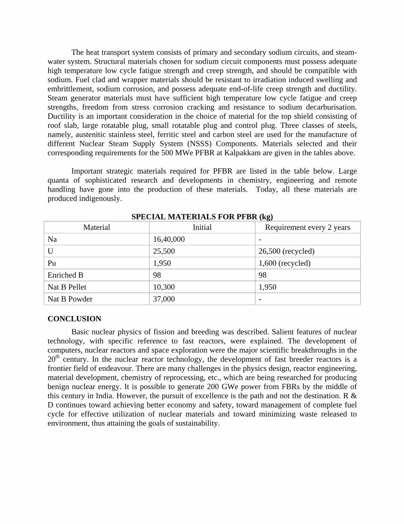
The heat transport system consists of primary and secondary sodium circuits, and steam-water system. Structural materials chosen for sodium circuit components must possess adequate high temperature low cycle fatigue strength and creep strength, and should be compatible with sodium. Fuel clad and wrapper materials should be resistant to irradiation induced swelling and embrittlement, sodium corrosion, and possess adequate end-of-life creep strength and ductility. Steam generator materials must have sufficient high temperature low cycle fatigue and creep strengths, freedom from stress corrosion cracking and resistance to sodium decarburisation. Ductility is an important consideration in the choice of material for the top shield consisting of roof slab, large rotatable plug, small rotatable plug and control plug. Three classes of steels, namely, austenitic stainless steel, ferritic steel and carbon steel are used for the manufacture of different Nuclear Steam Supply System (NSSS) Components. Materials selected and their corresponding requirements for the 500 MWe PFBR at Kalpakkam are given in the tables above. Important strategic materials required for PFBR are listed in the table below. Large quanta of sophisticated research and developments in chemistry, engineering and remote handling have gone into the production of these materials. Today, all these materials are produced indigenously.
SPECIAL MATERIALS FOR PFBR (kg) Material Initial Requirement every 2 years
Na 16,40,000 - U 25,500 26,500 (recycled) Pu 1,950 1,600 (recycled) Enriched B 98 98 Nat B Pellet 10,300 1,950 Nat B Powder 37,000 - CONCLUSION
Basic nuclear physics of fission and breeding was described. Salient features of nuclear technology, with specific reference to fast reactors, were explained. The development of computers, nuclear reactors and space exploration were the major scientific breakthroughs in the 20th century. In the nuclear reactor technology, the development of fast breeder reactors is a frontier field of endeavour. There are many challenges in the physics design, reactor engineering, material development, chemistry of reprocessing, etc., which are being researched for producing benign nuclear energy. It is possible to generate 200 GWe power from FBRs by the middle of this century in India. However, the pursuit of excellence is the path and not the destination. R & D continues toward achieving better economy and safety, toward management of complete fuel cycle for effective utilization of nuclear materials and toward minimizing waste released to environment, thus attaining the goals of sustainability.