TECHNISCHE MECHANIK, 34, 1, (2014), 3 – 11 submitted: September 16, 2013 A Phase-Field Approach to Damage Modelling in Open-Cell Foams A. Geringer, S. Diebels Foams are complex and challenging materials. The damage process of the foam materials takes place on multiple scales changing several physical and structural properties of the material. In this study, the topology-based vari- able describing the connectivity state of a cell is introduced to formulate a non-variational phase-field model for the damage evolution in an open-cell foam. The material is considered consisting of the damaged and unimpaired phase with the proposed phase-field variable describing the separation of phases. The performance of the compu- tational model is examined by means of the standard benchmarks such as tensile and simple shear test. The results show a qualitative correspondence with the two-dimensional artificial foam model used as a reference. Further- more, the influence of the directional data extracted from the microstructure is investigated. The utilisation of the connectivity-based damage variable turns out to be a suitable choice for the simulation of the damage evolution in open-cell foam materials. 1 Introduction The metallic foams are an advanced material which is becoming more and more attractive due to the unique combination of the mechanical properties such as high stiffness and low weight they offer. The increasing ac- knowledgement of the foams as an engineering material requires appropriate models for each aspect of this highly interesting material. The modelling of the damage effects is one of the challenges related to cellular materials. Several material properties are affected as a consequence of the damage process. The modelling of these effects is carried out using an auxiliary continuous variable representing the damage state. The field of continuum damage mechanics was pioneered by Kachanov (1958) who introduced the effective stress concept, describing a virtual state of the material without damage. The further development of the theoretical framework has taken place a few decades later. Lemaitre (1985), Murakami and Ohno (1981) extended the framework by defining the damage modelling for ductile materials. The works by Krajcinovic et al. deal with the modelling of the effects of damage on brittle materials (Krajcinovic and Fonseka (1981), Krajcinovic and Srinivasan (1983)). The damage evolution in plasticity was formulated by Kattan and Voyiadjis (1990). The multiscale nature of the damage is addressed in the works considering the description of failure mechanisms using a framework of extended continuum theories (Steinmann (1995), Ebinger et al. (2004), Grammenoudis et al. (2009), Forest (2009), Rinaldi and Placidi (2013)). The mechanical properties of foam materials are mainly defined by the material structure on the microscopic level. The characterisation of the cellular material microstructure can be made based on the porosity, mean cell diameter, dispersion of cell size, symmetry, the edge-connectivity, etc. (Gibson and Ashby (1999)). In the present contribution, the topological information obtained from the microstructure is used to define a damage evolution approach for an open-cell foam structure. Hereby the material is considered containing two distinct phases: the phase containing undamaged material and the phase with the material in damaged state. The damage variable is, therefore, used to describe the separation of these two phases together with the interface development. The solution of interfacial problems is the subject of the phase-field modelling. The evolution of the interface position is characterised by the evolution of the continuous phase-field variable, which takes two different values depending on the phase domain. In the interface area, the value of the phase-field variable is changing gradually so that a diffuse interface is formed. The phase-field method allows for the description of the microstructure evolu- tion in a wide range of applications such as solidification process (Artemev et al. (2001), Boettinger et al. (2002), Siquieri et al. (2007)), fracture mechanics ( Miehe et al. (2010a), Miehe et al. (2010b)), nucleation kinetics (Em- merich and Siquieri (2006)) and many others. The contributions provided by Qin and Bhadeshia (2010), Steinbach (2009), Moelans et al. (2008) and Chen (2002) offer an overview of the recent developments and applications of phase-field method. 3
Transcript
TECHNISCHE MECHANIK,34, 1, (2014), 3 – 11
submitted: September 16, 2013
A Phase-Field Approach to Damage Modelling in Open-Cell Foams
A. Geringer, S. Diebels
Foams are complex and challenging materials. The damage process of the foam materials takes place on multiplescales changing several physical and structural properties of the material. In this study, the topology-based vari-able describing the connectivity state of a cell is introduced to formulate a non-variational phase-field model forthe damage evolution in an open-cell foam. The material is considered consisting of the damaged and unimpairedphase with the proposed phase-field variable describing the separation of phases. The performance of the compu-tational model is examined by means of the standard benchmarks such as tensile and simple shear test. The resultsshow a qualitative correspondence with the two-dimensional artificial foam model used as a reference. Further-more, the influence of the directional data extracted from the microstructure is investigated. The utilisation of theconnectivity-based damage variable turns out to be a suitable choice for the simulation of the damage evolution inopen-cell foam materials.
1 Introduction
The metallic foams are an advanced material which is becoming more and more attractive due to the uniquecombination of the mechanical properties such as high stiffness and low weight they offer. The increasing ac-knowledgement of the foams as an engineering material requires appropriate models for each aspect of this highlyinteresting material. The modelling of the damage effects is one of the challenges related to cellular materials.
Several material properties are affected as a consequence of the damage process. The modelling of these effects iscarried out using an auxiliary continuous variable representing the damage state. The field of continuum damagemechanics was pioneered by Kachanov (1958) who introduced the effective stress concept, describing a virtualstate of the material without damage. The further development of the theoretical framework has taken place afew decades later. Lemaitre (1985), Murakami and Ohno (1981) extended the framework by defining the damagemodelling for ductile materials. The works by Krajcinovic et al. deal with the modelling of the effects of damageon brittle materials (Krajcinovic and Fonseka (1981), Krajcinovic and Srinivasan (1983)). The damage evolutionin plasticity was formulated by Kattan and Voyiadjis (1990). The multiscale nature of the damage is addressed inthe works considering the description of failure mechanisms using a framework of extended continuum theories(Steinmann (1995), Ebinger et al. (2004), Grammenoudis et al. (2009), Forest (2009), Rinaldi and Placidi (2013)).
The mechanical properties of foam materials are mainly defined by the material structure on the microscopiclevel. The characterisation of the cellular material microstructure can be made based on the porosity, mean celldiameter, dispersion of cell size, symmetry, the edge-connectivity, etc. (Gibson and Ashby (1999)). In the presentcontribution, the topological information obtained from the microstructure is used to define a damage evolutionapproach for an open-cell foam structure. Hereby the material is considered containing two distinct phases: thephase containing undamaged material and the phase with the material in damaged state. The damage variable is,therefore, used to describe the separation of these two phases together with the interface development.
The solution of interfacial problems is the subject of the phase-field modelling. The evolution of the interfaceposition is characterised by the evolution of the continuous phase-field variable, which takes two different valuesdepending on the phase domain. In the interface area, the value of the phase-field variable is changing gradually sothat a diffuse interface is formed. The phase-field method allows for the description of the microstructure evolu-tion in a wide range of applications such as solidification process (Artemev et al. (2001), Boettinger et al. (2002),Siquieri et al. (2007)), fracture mechanics ( Miehe et al. (2010a), Miehe et al. (2010b)), nucleation kinetics (Em-merich and Siquieri (2006)) and many others. The contributions provided by Qin and Bhadeshia (2010), Steinbach(2009), Moelans et al. (2008) and Chen (2002) offer an overview of the recent developments and applications ofphase-field method.
3
lenz
Texteingabe
DOI: 10.24352/UB.OVGU-2017-049
Open-cell foam structures can be modelled using beam elements on the microscale. The reference model usedin the present contribution to incorporate the directional data from the microstructure is provided by the two-dimensional artificial lattice structure consisting of standard finite elements (Mangipudi and Onck (2011), Oncket al. (2001), Tekoglu and Onck (2008), Reis and Ganghoffer (2010, 2012)). This level of microstructure dis-cretization provides a detailed description of the foam material, resulting, however, in an inevitable large numberof degrees of freedom and consequential computational limitations.
The utilisation of the phase-field approach in the context of damage mechanics as proposed in the current contribu-tion offers the advantage of modelling the damage zone propagation in an open-cell foam without full discretizationof the microstructure.
2 Phase-Field Model
In the damage modelling approach described here in following the isotropic and linear elastic material behaviouris assumed. The edge-connectivity characteristic for cellular materials, among numerous material properties, isaffected by the damage process taking place on multiple scales.
Ze = 4
Ze = 1
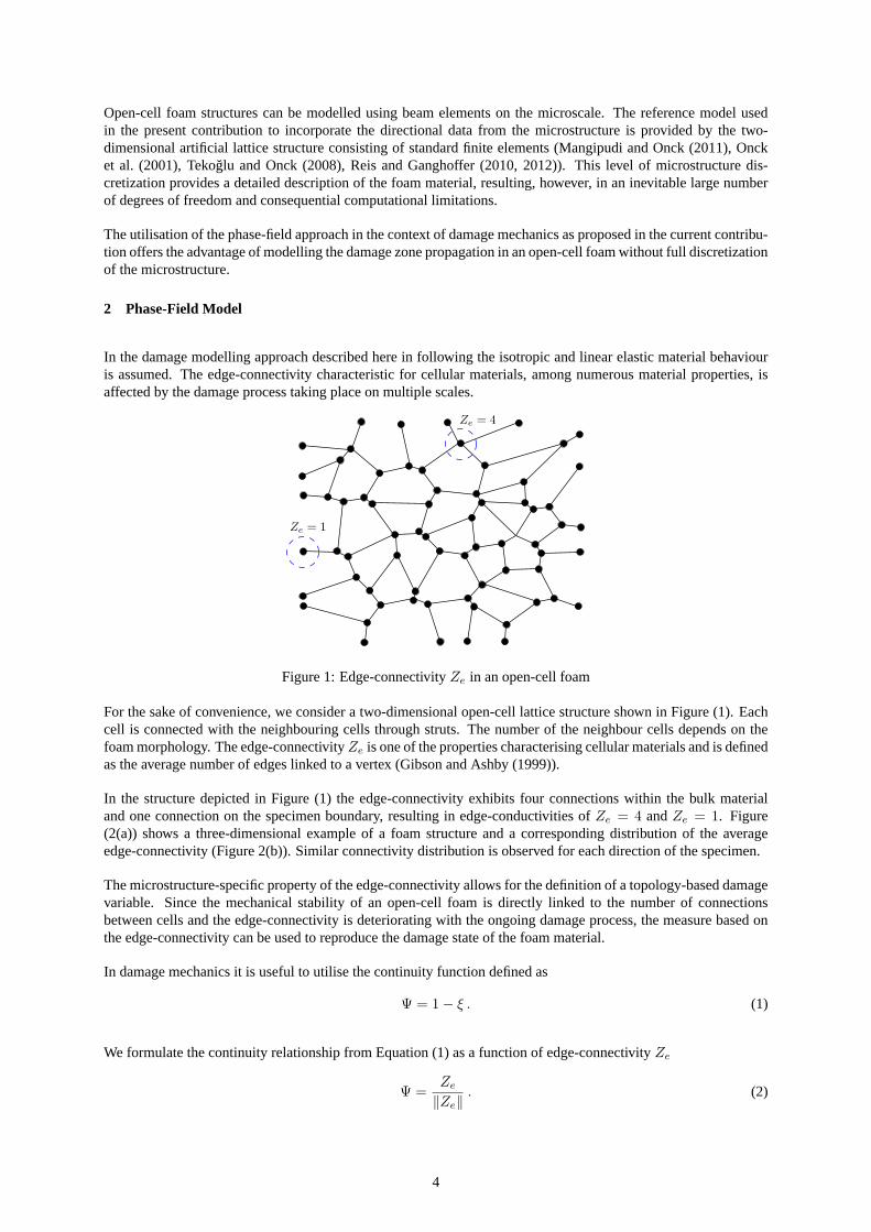
Figure 1: Edge-connectivityZe in an open-cell foam
For the sake of convenience, we consider a two-dimensional open-cell lattice structure shown in Figure (1). Eachcell is connected with the neighbouring cells through struts. The number of the neighbour cells depends on thefoam morphology. The edge-connectivityZe is one of the properties characterising cellular materials and is definedas the average number of edges linked to a vertex (Gibson and Ashby (1999)).
In the structure depicted in Figure (1) the edge-connectivity exhibits four connections within the bulk materialand one connection on the specimen boundary, resulting in edge-conductivities ofZe = 4 andZe = 1. Figure(2(a)) shows a three-dimensional example of a foam structure and a corresponding distribution of the averageedge-connectivity (Figure 2(b)). Similar connectivity distribution is observed for each direction of the specimen.
The microstructure-specific property of the edge-connectivity allows for the definition of a topology-based damagevariable. Since the mechanical stability of an open-cell foam is directly linked to the number of connectionsbetween cells and the edge-connectivity is deteriorating with the ongoing damage process, the measure based onthe edge-connectivity can be used to reproduce the damage state of the foam material.
In damage mechanics it is useful to utilise the continuity function defined as
Ψ = 1 − ξ . (1)
We formulate the continuity relationship from Equation (1) as a function of edge-connectivityZe
Ψ =Ze
‖Ze‖. (2)
4
(a) Artificial foam structure
1.6
1.8
2
2.2
2.4
2.6
2.8
3
3.2
3.4
0 0.2 0.4 0.6 0.8 1
x
Ze
(b) Edge-connectivityZe over normalised specimen length
Figure 2: Foam structure and the corresponding average edge-connectivity distribution
Regarding Equation (1) the topology-based damage variable reads as follows
ξ = 1 −Ze
‖Ze‖. (3)
The damage variable takes the values0 ≤ ξ ≤ 1, with ξ = 0 for the material without damage (i. e. the cell has fullnumber of connections) andξ = 1 for fully damaged material (i. e. most of the connections to neighbouring cellsare lost).
0
0.1
0.2
0.3
0.4
0.5
0.6
0.7
0.8
0.9
1
0 0.2 0.4 0.6 0.8 1
x
u
Figure 3: Approximation of the edge-connectivity using a differential equation
In the following we consider a domainΩ with a boundary denoted by∂Ω. The boundary consists of two non-overlapping regionsΓD andΓN with ΓD
⋃ΓN . The average connectivity distribution of a foam structure can be
approximated using a phenomenological approach based on a partial differential equation of the Helmholtz type
−div (β grad u) + α u − f = 0 . (4)
The structure of the Equation (4) exhibits the structure of the general balance equation (cf. Steeb and Diebels(2004)). This framework allows for a general thermodynamically consistent formulation of field equations. Anexample for a solution of Equation (4) is shown in Figure (3). The shape of the solution curve depicted in Figure (3)can be adjusted to reproduce the connectivity distribution curve by solving Equation 4 with a set of the appropriateparameters.
Combining the definition of the topology-based damage variable from Equation (2) and extending Equation (4)
5
with the time derivative the evolution equation of the damage for an open-cell foam is governed
∂ξ
∂t= −div (β grad ξ) + α(1 − ξ) ξ − f , (5)
with boundary conditions
ξ = gξ on ΓDξ (6)
∂ξ
∂n= hξ on ΓN
ξ , (7)
with n as an outward unit normal vector on boundary∂Ω. In the following examples the Dirichlet boundarycondition is chosen to describe the influence of free boundaries on the connectivity, i. e. to take into account thereduced connectivity close to free boundaries. In contrast the Neumann boundary condition is chosen in the senseof a symmetry condition. In this casehξ = 0 preserves the connectivity close to these boundaries. The secondterm on the right hand side of the Equation (5) represents the contribution to the damage field arising from thelocal interactions.
To complete the formulation of the proposed damage model the evolution Equation (5) is coupled with the defor-mation field which is the result of the solution of the linear elastic problem. The coupling is accomplished using thethird term of Equation (5) which is, therefore, defined as a function of the strain energyW and the first principalstrain
f = f(W, ε1) , (8)
with the strain energy defined as
W =12
T : ε . (9)
The damage affects the deformation field through the effective stressT which describes a virtual state of thematerial without damage
T =T
(1 − ξ). (10)
The linear elastic problem coupled with the damage evolution is given by an equilibrium equation with neglectedbody forces in static case
div T = 0 , (11)
and the constitutive relation for the Cauchy stress tensor
T = 2μ ε + λ (tr ε) I , (12)
with μ andλ as the classical Lame parameter. The linear strain tensor is provided in terms of the displacementvectoru by
ε =12(gradu + grad T u) . (13)
The boundary conditions of the linear elastic problem are given by the displacement and stress vectors on respectiveboundaries
u = gu on ΓDu (14)
T ∙ n = hu on ΓNu . (15)
6
ξ = 1ξ = 1
ξ = 1
∂ξ
∂n= 0
∂ξ
∂n= 0
(a) Tensile test
ξ = 1
ξ = 1
ξ = 1
∂ξ
∂n= 0
∂ξ
∂n= 0
(b) Shear test
Figure 4: Single-edge notched specimen
3 Results and Discussion
The governing equations of the damage model presented here are the evolution Equation (5), the displacement-strain relation (13), the equilibrium Equation (11), and the constitutive Equation (12). The combination of theseequations leads to a two-way coupled problem in the fieldsu andξ. The numerical solution of this problem isaccomplished by means of the finite element method. The set of coupled equations is solved using COMSOLMultiphysics (2009) for a given boundary conditions.
In the following examples, the performance of the proposed damage modelling approach is demonstrated. For thispurpose we consider two standard benchmark problems such as a tensile and a pure shear tests performed on asingle-edge notched square specimen with equal-length sides of100mm. The geometry of the specimen and theboundary conditions used for the tests are depicted in Figures (4(a)) and (4(b)). The computations in both examplesare performed with monotonic driven displacements with a constant increment ofΔu = 0.02 mm. The maximumprescribed displacement amounts tou = 1mm.
The value ofξ = 1 is given as the boundary condition for the free boundaries of the specimen since the cells onthese boundaries exhibit the small edge-connectivity values resulting in values ofξ → 1. The boundaries withconstraints originating from the mechanical part of problem are marked as Neumann boundaries with∂ξ
∂n = 0.
The computed propagation of the damage zone resulting from the tensile test is shown in Figures (5(a) - 5(c)). Thered colour corresponds to the state of the total damage where only one connection to the neighbour cells is left andthe blue colour displays the undamaged state of the structure where all of the connections to the neighbours arepresent. The tensile test leads to the propagation of the damage zone in horizontal direction.
(a) u = 0.34mm (b) u = 0.38mm (c) u = 0.42mm
Figure 5: Damage field distribution in a single-edge notched tensile test
The second example explores the evolution of the damage resulting from the shear test performed on a specimendisplayed in Figure (4(b)). The resulting damage evolution is depicted in Figures (6(a) - 6(c)). The evolution of
7
(a) u = 0.72mm (b) u = 0.80mm (c) u = 0.92mm
Figure 6: Damage field distribution in a single-edge notched shear test
the damage field is different from the one in a tensile test case. The damage zone takes the path from the notchdown to the right bottom corner of the specimen.
The effect of the model parametersα andβ on the damage variable evolution is evaluated in a standard tensile testperformed with different parameter values. The values of the damage variableξ are computed in a point close tothe notch tip. From Figure (7(a)), one can clearly recognise that both parameters have significant influence uponthe evolution of the damage zone. While the increasing values of the parameterβ are speeding up the damageprogression, performing the same with the values of the second parameterα forces the damage zone propagationto slow down.
0
0.2
0.4
0.6
0.8
1
0 0.1 0.2 0.3 0.4 0.5
α = 10
α = 0.001
α = 100
α = 1
u
ξ
(a) 0.001 ≤ α ≤ 1000 , β = 1.0
0
0.2
0.4
0.6
0.8
1
0 0.05 0.1 0.15 0.2 0.25 0.3 0.35 0.4
β = 0.1
β = 100
β = 10
β = 1
u
ξ
(b) 0.1 ≤ β ≤ 100 , α = 0.001
Figure 7: Parameter study
The influence of the microstructure on the damage zone evolution can be additionally increased by consideringthe local strut orientation of the foam cell. The orientation distribution function (ODF) is a generalisation ofthe directional data, representing the fraction of single elements with particular direction (Kanatani (1984)). Theorientation distribution functionρ(n)
ρ = ρ(n) = Fij ni nj , (16)
corresponding to the microstructure, is approximated using the fabric tensor of the second kindF and the fabrictensor of the first kindN (Kanatani (1984), Voyiadjis and Kattan (2006))
Fij =152
(
Nij −15δij
)
, (17)
Nij =1N
N∑
k=1
n(k)i n
(k)j , (18)
with n as a unit vector indicating the strut orientation. The distribution function determined using the fabric tensor
As an example, we consider a tensile test performed on a single-edge notched specimen constructed as a two-dimensional artificial foam structure. Each strut of the specimen is discretized using standard Timoshenko beamelements. The computations are performed using the FE-solver RADIOSS (Altair Engineering RADIOSS (2012)).During the tensile test computation the beam elements with the highest values of the von Mises stress are consid-ered failed foam struts which are consequently deleted. Figures (8(a) - 8(c)) depict the crack propagation in theartificial foam structure.
(a) t = 0.01 (b) t = 0.5 (c) t = 1
Figure 8: Single-edge notched shear test performed on an artificial foam structure (normalised time values)
The directional data of the beams in the reference microstructure model is transferred to the phase-field modelusing the orientation distribution functionρ(n), (Equation 16). Now, the tensile test is performed using modifiedphase-field formulation (Equation 19). The obtained damage zone distribution is shown in Figures (9(a) - 9(c)).
(a) u = 0.38mm (b) u = 0.46mm (c) u = 0.50mm
Figure 9: Damage field distribution resulting from the model incorporating directional data
The comparison of the damage zone distribution acquired with phase-field model incorporating the directional dataand crack path from the reference model demonstrates a qualitative similarity of the results.
The presented phase-field formulation is constructed without a variational minimisation of a free energy functionalproviding the advantage of a high flexibility in the description of microstructure evolution in open-cell foams.The model can be further extended with regard to different constitutive models as well as finite strain theory.Apart from, the coupling of the damage phase-field with the deformations, other coupling mechanisms (chemical,temperature, etc.) can also be incorporated into the model formulation.
The phase-field formulation used in this study describes the evolution of connectivity which is linked directly to thedamage state of an open-cell foam material. As a matter of fact, with the ongoing damage process the connectivitybetween the cells of a foam material is getting irrecoverably lost. Hence, the variable based on this topologicalproperty features the character of a non-conserved variable of the corresponding phase-field formulation. The
9
inspection of the evolution Equation (5) and the Cahn-Hillard or Allen-Cahn equations often used in the phase-field formulations (Qin and Bhadeshia (2010), Moelans et al. (2008) ) reveals these three equations as a reaction-diffusion equations, described in terms of an order-parameter and its gradients. This categorisation and also thenon-conserving character of the connectivity-based phase-field variable emphasise the similarity of the proposedformulation with the equations used in variational phase-field formulations.
4 Conclusions
In the present contribution a non-variational phase-field approach is presented which allows for the description ofthe damage evolution in the open-cell foam materials. The topological property characterising the microstructuresuch as the edge-connectivity is used as the basis for the development of the proposed approach. The numericalresults show that the connectivity-based variable drives the evolution of the damage phase field. The presentedapproach provides advantages in the description of the microstructural changes resulting from the damage processin open-cell structures. The possibility of incorporating the directional data of the microstructure by means of theorientation distribution function approximated with fabric tensors is examined. The performance of the proposedformulation and the effects of the model parameters on the overall behaviour of the model are shown by means ofthe respective numerical examples and parameter studies.
References
Artemev, A.; Jin, Y.; Khachaturyan, A.: Three-dimensional phase field model of proper martensitic transformation.Acta Materialia, 49, 7, (2001), 1165–1177.
Chen, L.-Q.: Phase-field models for microstructure evolution.Annual Review of Materials Science, 32, (2002),113–140.
COMSOL Multiphysics:Version 3.5a. COMSOL AB, Stockholm, Sweden (2009).
Ebinger, T.; Steeb, H.; Diebels, S.: Higher order continuum models for cellular materials including damage.PAMM, 4, 1, (2004), 276–277.
Emmerich, H.; Siquieri, R.: Investigating heterogeneous nucleation in peritectic materials via the phase-fieldmethod.Journal of Physics: Condensed Matter, 18, 49, (2006), 11121.
Forest, S.: Micromorphic approach for gradient elasticity, viscoplasticity, and damage.Journal of EngineeringMechanics, 135, 3, (2009), 117–131.
Gibson, L.; Ashby, M.:Cellular solids: structure and properties. Cambridge university press (1999).
Grammenoudis, P.; Tsakmakis, C.; Hofer, D.: Micromorphic continuum. part ii: Finite deformation plasticitycoupled with damage.International Journal of Non-Linear Mechanics, 44, 9, (2009), 957–974.
Kachanov, L.: On creep rupture time.Izv. Acad. Nauk SSSR, Otd. Techn. Nauk, 8, (1958), 26–31.
Kanatani, K.-I.: Distribution of directional data and fabric tensors.International Journal of Engineering Science,22, 2, (1984), 149–164.
Kattan, P. I.; Voyiadjis, G. Z.: A coupled theory of damage mechanics and finite strain elasto-plasticityi. damageand elastic deformations.International Journal of Engineering Science, 28, 5, (1990), 421–435.
Krajcinovic, D.; Fonseka, G.: The continuous damage theory of brittle materials, part 1: general theory.Journal ofApplied Mechanics, 48, (1981), 809.
Krajcinovic, D.; Srinivasan, M.: Dynamic fracture of concrete (1983).
Lemaitre, J.: Continuous damage mechanics model for ductile fracture.Journal of Engineering Materials andTechnology, Transactions of the ASME, 107, 1, (1985), 83–89.
Mangipudi, K.; Onck, P.: Multiscale modelling of damage and failure in two-dimensional metallic foams.Journalof the Mechanics and Physics of Solids, 59, 7, (2011), 1437–1461.
10
Miehe, C.; Hofacker, M.; Welschinger, F.: A phase field model for rate-independent crack propagation: Robustalgorithmic implementation based on operator splits.Computer Methods in Applied Mechanics and Engineering,199, 45, (2010a), 2765–2778.
Miehe, C.; Welschinger, F.; Hofacker, M.: Thermodynamically consistent phase-field models of fracture: Varia-tional principles and multi-field fe implementations.International journal for numerical methods in engineering,83, 10, (2010b), 1273–1311.
Moelans, N.; Blanpain, B.; Wollants, P.: An introduction to phase-field modeling of microstructure evolution.Calphad: Computer Coupling of Phase Diagrams and Thermochemistry, 32, 2, (2008), 268–294.
Murakami, S.; Ohno, N.: A continuum theory of creep and creep damage. In:Creep in structures, pages 422–444,Springer (1981).
Reis, F. D.; Ganghoffer, J.: Discrete homogenization of architectured materials: Implementation of the methodin a simulation tool for the systematic prediction of their effective elastic properties.Technische Mechanik, 30,(2010), 85–109.
Reis, F. D.; Ganghoffer, J.: Equivalent mechanical properties of auxetic lattices from discrete homogenization.Computational Materials Science, 51, 1, (2012), 314–321.
Rinaldi, A.; Placidi, L.: A microscale second gradient approximation of the damage parameter of quasi-brittle het-erogeneous lattices.ZAMM-Journal of Applied Mathematics and Mechanics/Zeitschrift fur Angewandte Mathe-matik und Mechanik.
Siquieri, R.; Emmerich, H.; Jurgk, M.: Computation of solidification problems with hydrodynamic convectionresolving energetic anisotropies at the microscale quantitatively.European Physical Journal: Special Topics,149, 1, (2007), 27–41, cited By (since 1996)3.
Steeb, H.; Diebels, S.: Modeling thin films applying an extended continuum theory based on a scalar-valued orderparameter.: Part i: isothermal case.International Journal of Solids and Structures, 41, 18, (2004), 5071–5085.
Steinbach, I.: Phase-field models in materials science.Modelling and Simulation in Materials Science and Engi-neering, 17, 7, (2009), 073001.
Steinmann, P.: Theory and numerics of ductile micropolar elastoplastic damage.International journal for numeri-cal methods in engineering, 38, 4, (1995), 583–606.
Tekoglu, C.; Onck, P.: Size effects in two-dimensional voronoi foams: a comparison between generalized continuaand discrete models.Journal of the Mechanics and Physics of Solids, 56, 12, (2008), 3541–3564.
Voyiadjis, G. Z.; Kattan, P. I.: Damage mechanics with fabric tensors.Mechanics of Advanced Materials andStructures, 13, 4, (2006),285–301.
Address: Prof. Dr.-Ing. Stefan Diebels, Dipl.-Ing. Alexander Geringer, Saarland University, Chair of AppliedMechanics, D-66123 Saarbrucken, GermanyE-mail: [email protected], [email protected]