40
COMPOSITE INSULATORS FOR HV EQUIPMENTS A. Pigini On behalf of CIGRE WG A3 21 Summary of the presentation at IEEE PES Switchgear Committee meeting Myrtle Beach 29 april 2010
COMPOSITE INSULATORS FOR HV EQUIPMENTS
A. Pigini
On behalf of CIGRE WG A3 21
Summary of the presentation at IEEE PES Switchgear Committee meeting Myrtle Beach 29 april 2010

1-Introduction
• Active parts interact with the insulating housing and may influence the behaviour of the housing itself and of the full equipment.
• A CIGRE working group was created within SC A3 aimed at considering the major aspects of this interaction: i.e thermal, mechanical, electrical and environmental.
• The title of the WG is “WG A3 21: Aspects for the application of non-ceramic insulators to HV and MV apparatus “. Michele de Nigris is the Convener of the WG while Alberto Pigini is the Secretary.
• The WG has 25 Members from 17 nations

1-IntroductionThe WG initiated in 2006 and had 6 meetings since that time. It will completed the first part of the activity, dealing with HV, within 2009

1-Introduction
• The main product of this first part is a Cigre brochure dealing with “Application of polymeric insulation to HV equipments”.
• Pending the approval of the SC the WG, possibly renewated, will continue with the MV matter.

1-Introduction
The CIGRE Brochure includes the following Chapters:
• introduction
• application of polymeric materials to the external insulation of apparatus and components
• service and field experience of HV equipment with polymeric housing
• present IEC standards and their applicability to apparatus and components with polymeric insulation
• interactions of the inner active parts in terms of electric fields
1-Introduction
• the influence of the equipment active parts on the short- and long-term electrical performance in various environments
• mechanical and thermal interactions of the active parts
• chemical interactions
• handling and maintenance
• life cycle costing and environmental impact aspects
• UHV AC and DC applications
• conclusions

1-Introduction
• All the WG members gave important contributions to the documents, collected and organized by the responsible authors of each Chapter.
• A preliminary summary of the main aspects dealt with in the WG is here reported. For more detailed information reference to the CIGRE brochure is recommended

2- Application of polymeric materials to the external insulation of apparatus and components
Basically the applications can be grouped into two technologies :a) Hollow composite insulatorsb) The outdoor insulating material applied directly, e.g. by moulding

2- Application of polymeric materials …Applications of composite insulators to HV apparatus
Type of
apparatus Design Directly moulded
Hollow
core
insulator
Solid
core
insulator
Insulation media
Station Post
insulators Yes
Yes, filled
with gas
/liquid or
solid
insulation
Yes gas, solid, liquid
Circuit
breakers
Live tank No Yes No Gas
Dead tank (also
GIS) No
Yes,
principally
a bushing
No Gas
Generator CB No
Yes,
principally
a bushing
No Gas
Switches Line switch No Yes Gas
Ground switch No Yes Gas
Disconnectors No Yes Yes gas, solid, liquid
Surge
arresters Yes Yes No gas, solid
Instrument
transformers
CT Yes Yes No gas
VT Yes < 110 kV Yes No gas, solid, liquid
CVT Yes < 110 kV Yes No gas, solid, liquid
Optical sensors Yes Yes Yes gas, solid, liquid
Bushings
Wall bushings Yes, RIP Yes No gas, solid, liquid
Transformer
bushings Yes, RIP Yes No gas, solid, liquid
Combined
equipment
Bushing and cable
terminations with
integrated Surge
arrester
No Yes No gas, solid
Surge arrester
used as post
insulator
Yes Yes No gas, solid
Disconnector
Circuit Breaker Yes Yes Yes Gas
Cable
terminations Yes (premanufactured) Yes No gas, solid, liquid

2- Application of polymeric materials….
Main design stresses for the various applications
Design
stresses
Electro
Environmental
Chemical Mechanical
Electric
field +
pollution,
rain
Thermal External
loads
Pressure
(e.g. short
circuit)
Seismic
Post
insulators
X X X
Circuit
breakers
X X X X X X
Switches X X X X X X
Disconnectors X X X
Surge
arresters
X X X X X X
Instrument
transformers
X X X X X X
Bushings X X X X X X
Combined
equipment
X X X X X X
Optical fibres X X X

2- Application of polymeric materials…. Composite insulators: advantages and precautions
Electro
Environmental Thermal Chemical Mechanical Others
Advantages
Safety
Not affected
by thermal
shock
Hydrophobicity Safety Low life cycle cost
No cleaning, no
maintenance No explosion
One single piece up
to UHV
Design flexibility Low weight
Manufacturing
flexibility and short
manufacturing time
High
performances
under pollution
Less critical
to vandalism
Easy handling and
installation
Predictable
mechanical
behaviour
Not fragile
Precautions
Design and
material
knowledge for
long term
reliability
Temperature
limit of -55 /
+110°C
Compatibility
with SF6 by-
products and
oil
Vapour
permeation
Can be damaged by
handling and
installation
Attack by animals
during storage

3 -Service and field experience of HV equipment with polymeric housing
• The experience with HV equipment with polymer housing started at industrial scale in 80’s.
• Since then the total number of hollow core insulators in service is of about half a million (2006) and the present market consists of about 50.000 insulators/year for a market value of 50 millions Euro. The yearly growth rate is typically of two digits (10-20%).
• If directly moulded apparatus >60 kV are considered for such applications as surge arresters, cable terminations and bushings, there are probably another million of units in service mainly for applications below 145 kV.

3 -Service and field experience of HV equipment with polymeric housing
Polymer housing penetration in % for HV apparatus
Polymer Penetration in HV Apparatus
HV Apparatus Type <170 kV 245 kV >360 kV
Live Tank Circuit Breakers <5-10% <5-10% <5-10%
Dead Tank Circuit Breakers Bushings >30% >30% >70%
Gas Insulated Station Bushings >30% >50% >50%
Combined Circuit Breakers Bushings >90% >90% >90%
RIP Bushings (Wall/Transformer) >50% >50% >50%
Gas Bushings (Wall/Transformer) >50% >50% >50%
OIP Bushings (Wall/Transformer) 10-20% 10-20% 10-20%
Oil Instrument Transformers 10-20% 10-20% 10-20%
Gas Instrument Transformers >50% >50% >50%
Cable terminations* >50% >60% >80%
Surge Arresters * >10% >10% >10%
*Polymer housing with hollow insulators only. If all directly moulded components are considered the
polymer penetration is close to 100% for voltages <170 kV and 40-50% for >245 kV

3 -Service and field experience of HV equipment with polymeric housing
• Information was also collected through questionnaires and interviews with WG members.
• Responses dealt with data of more than 7 nations, 2000 apparatus and covering a service experience up to about 20 years. Response details are given in the Brochure.
• In general, the reported service experience was positive. Only minor degradation were pointed out like loss of hydrophobicity or biological growth observed in a few cases.
3 -Service and field experience of HV equipment with polymeric housing
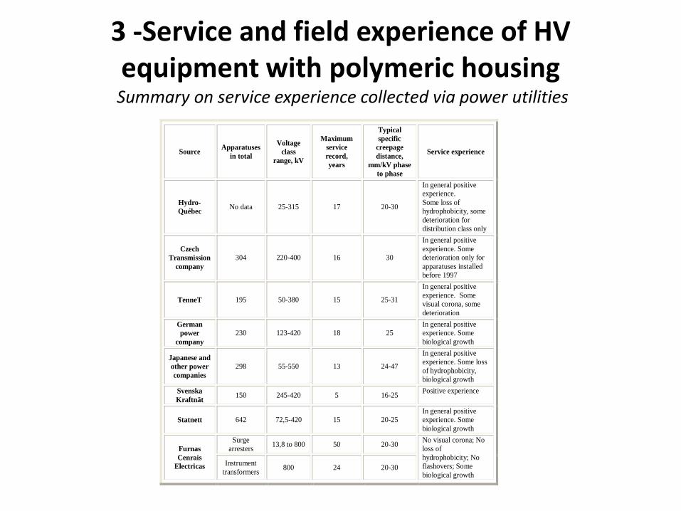
Summary on service experience collected via power utilities
Source Apparatuses
in total
Voltage
class
range, kV
Maximum
service
record,
years
Typical
specific
creepage
distance,
mm/kV phase
to phase
Service experience
Hydro-
Québec No data 25-315 17 20-30
In general positive
experience.
Some loss of
hydrophobicity, some
deterioration for
distribution class only
Czech
Transmission
company
304 220-400 16 30
In general positive
experience. Some
deterioration only for
apparatuses installed
before 1997
TenneT 195 50-380 15 25-31
In general positive
experience. Some
visual corona, some
deterioration
German
power
company
230 123-420 18 25
In general positive
experience. Some
biological growth
Japanese and
other power
companies
298 55-550 13 24-47
In general positive
experience. Some loss
of hydrophobicity,
biological growth
Svenska
Kraftnät 150 245-420 5 16-25
Positive experience
Statnett 642 72,5-420 15 20-25
In general positive
experience. Some
biological growth
Furnas
Cenrais
Electricas
Surge
arresters 13,8 to 800 50 20-30
No visual corona; No
loss of
hydrophobicity; No
flashovers; Some
biological growth
Instrument
transformers 800 24 20-30

3 -Service and field experience of HV equipment with polymeric housing
• The service experience is complemented by the long term experience (up to 8 years) in outdoor test stations representing rather severe conditions, among them coastal (Dungeness and Kelso), inland (Ludvika) and semi-desert (Negev), examined in detail in the brochure.
• One of the conclusions in of the experience in the test stations is that it could be possible for composite housing to reduce creepage distances in coastal areas at least one pollution level, compared to the values prescribed by IEC 60815

4- Present IEC standards and their applicability to apparatus and components with polymeric insulation
• The IEC 61462 2007 Standard is the basic reference • IEC 61462 are minimum requirements which should be
integrated by specific requirements by End-Users or by Equipment Manufacturers specifications, considering the function of the apparatus and the consequent insulator mechanical and thermal requirements.
• IEC 61462 does not specifically cover the case where the housing is an integral part of the main equipment construction. These solutions require specific considerations to be taken also into account in the Standards and Specifications of the specific components

4- Present IEC standards and their applicability to apparatus and
components with polymeric insulationExamples of aspects not covered:
• The housing performance may depend on the equipment inside or outside the composite hollow insulators; this matter is not covered.
• The practical use of composite hollow insulators covers both a.c. and d.c. applications. Specific tracking and erosion test procedure for d.c. applications has not yet been defined and accepted.
• Pollution tests according to IEC 60507 are not included as they are not applicable. Specific pollution tests for polymeric insulators are under consideration.
• The standard does not prescribe dielectric tests because the withstand voltages are not characteristics of the hollow insulator itself, but of the apparatus.
• All the design tests, apart from the thermal-mechanical test, are performed at normal ambient temperature. Extreme service temperatures may affect the mechanical behaviour of composite insulators. At the time being test protocols are left to the agreement between manufacturers and users.

4- Present IEC standards and their applicability to apparatus and components with polymeric insulation
The following aspects need to be considered:• Standards specify a unit sample which may need to be
specially produced for HV application and whose representativeness is to be analysed.
• The need of tests to asses the interaction of the active parts inside the housing on the short and long term performance of the housing iteslf
• The need of special tests to assess the thermal and chemical interaction of the housing with the inner parts
• Mechanical interactions and the need of special tests to assess the actual component performance (as an example to assess the seismic performance, the short circuit performance, and so on).

5- Interactions of the active parts in terms of electric field
Excessively high electrical field can have various consequences:
• Creation of partial discharges inside the solid materials in voids,
• Electric fields can be especially critical at triple points (e.g. locations where a metallic part, an insulating part and gas are joining).
• Appearance of “water drop corona” at the surface of the insulator.
• Creation of electrical discharges in the air
• As the insulators are polluted, the electrical field distribution is changed and critical field values can occur locally.
6- The influence of the equipment internal active parts on the short-and-long-term electrical performance in
various environments
The chapter includes two sections:
• electrical performance under short-term tests.
• electrical performance under long-term conditions.
This includes both the reference condition (i.e. without internal active parts) and the influence of active parts.

6- The influence of the equipment internal active parts on the short-and-long-term electrical performance in
various environments
0
0,2
0,4
0,6
0,8
1
1,2
1,4
1,6
1,8
200 300 400 500 600 700 800
D (mm)
lF/l
F(c
ap
an
d p
in)
(p.u
.)
ceramic
composites
Housing pollution performance

6- The influence of the equipment internal active parts on the short-and-long-term electrical performance in
various environments
0,5
0,6
0,7
0,8
0,9
1
1,1
0 100 200 300 400 500 600D (mm)
Uw
et/
Ud
ry
porcelain
composite
Housing performance under rain

6- The influence of the equipment internal active parts on the short-and-long-term electrical performance in
various environments
• AC-SI tests A lower reduction of the flashover voltage under wet condition for insulators of the same diameter; a lower dependence of the reduction on the insulator diameter;
• AC pollutions tests. A better performance with lower required creepage distance (about 20%less); a lower dependence of the required creepage distance on the insulator diameter.

6- The influence of the equipment internal active parts on the short-and-long-term electrical performance in
various environments
Aluminium sphere
Aluminium pipe
Aluminium top fitting
Silicone sheds
Fiberglass epoxy tube
Alluminium bottom fitting
(300mm diameter)
(100mm diameter)
60
0 m
m

6- The influence of the equipment internal active parts on the short-and-long-term electrical performance in
various environmentsclean condition
0,9
0,92
0,94
0,96
0,98
1
1,02
0 100 200 300 400 500 600 700Electrode lenght (mm)
U/U
ref(
p.u
.)
dry
wet

6- The influence of the equipment internal active parts on the short-and-long-term electrical performance in
various environments pollution
0,8
0,85
0,9
0,95
1
1,05
1,1
1,15
1,2
0 100 200 300 400 500 600 700
length of inner electrode (mm)
lf/lfr
ef

6- The influence of the equipment internal active parts on the short-and-long-term electrical performance in
various environments
• The influence of the inner electrodes is appreciable for dry and wet tests in clean conditions. Tests on the fully assembled equipment are therefore recommended;
• the influence is limited under pollution. Tests on housing can be extended to the equipments to which the insulators are applied, as far as the surface performance is concerned

6- The influence of the equipment internal active parts on the short-and-long-term electrical performance in
various environments
Performance under long term tests
Preliminary conclusion
•tests on empty housing in general representative also for apparatus,
provided the gradients lower than design gradients for the housing.
•The influence can become more evident for more compact designs.

7- Mechanical and thermal interaction
• The Mechanical and thermal interactions of the active parts and their influence on the insulator behaviour during its life in the HV electrical apparatus are not taken fully into consideration in the IEC 61462 Standards
• As previously mentioned, also for mechanical testing, the testing procedures indicated by IEC 61462 are minimum requirements
• The Service temperature, the Pressure (SIP) and bending (SML) requirements as well as the definition of tightness may be different depending on the application,
• The insulator may be considered as appropriate for intended use only after the equipment of which it is a part has satisfactorily passed the type tests called for by the particular standards to which the equipment must comply.
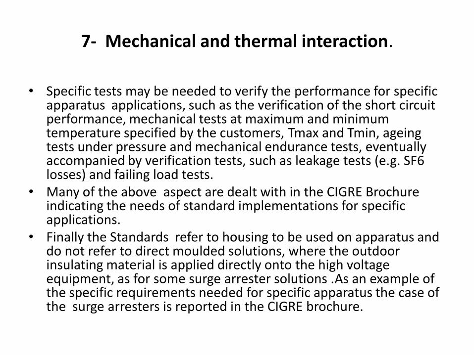
7- Mechanical and thermal interaction.
• Specific tests may be needed to verify the performance for specific apparatus applications, such as the verification of the short circuit performance, mechanical tests at maximum and minimum temperature specified by the customers, Tmax and Tmin, ageing tests under pressure and mechanical endurance tests, eventually accompanied by verification tests, such as leakage tests (e.g. SF6 losses) and failing load tests.
• Many of the above aspect are dealt with in the CIGRE Brochure indicating the needs of standard implementations for specific applications.
• Finally the Standards refer to housing to be used on apparatus and do not refer to direct moulded solutions, where the outdoor insulating material is applied directly onto the high voltage equipment, as for some surge arrester solutions .As an example of the specific requirements needed for specific apparatus the case of the surge arresters is reported in the CIGRE brochure.

8- Chemical interactions of inner fluids in non-ceramic insulator housings
• The hollow insulators may be filled with gases and fluids, SF6 and oil being the most used fluids. It is thus important to assure and verify the compatibility of the filler with the inner housing material.
• IEC standard to verify the performance of housing for application involving SF6 are not available at the time being. Each apparatus manufacturer has developed his own qualification procedure. Examples of adopted procedures are given in the CIGRE Brochure.The development of new standards about this aspect could be useful.
• Before the use of any oil type within specific housing material may ask to verify the full compatibility in terms of material and manufacturing process. Also in this case manufacturers have developed their own qualification procedures. The development of new standards on this aspect also could be useful.
9 Handling and maintenance
• As mentioned in CIGRE’s thematic brochure N°184 “Composite insulator handling guide” specific to overhead line insulators, most damages can be attributed to errors during transport, un-packing, re-packing, manipulation and storage of the insulators.
• In this chapter, CIGRE’s thematic brochure N°184 was adapted to composite hollow core insulators. Procedures and rules are given for:– Un-packing and re-packing
– Methods of storage
– Handling and cleaning.

10- Life cycle costing and environmental impact evaluation
For sake of exemplification reference is made to bushings
• Comparison of 30 years life cost of porcelain bushing and composite bushing solutions having the same profile and length is made. The assumption is made that, in the environment considered, porcelain is to be maintained, while composite can be exploited without maintenance.
• The cost of maintenance depends on the maintenance frequency and solution.
• Many variables and options are analyzed illustrating possible advantages of composite solutions.

10- Life cycle costing and environmental impact evaluation
• In terms of environmental impacts, calculations have been carried out following the requirements of the international standards ISO 14040 and comparing the impacts on the environment of the porcelain and composite bushing with rated voltages ranging from 245 kV to 1100 kV.
• The different impacts are identified in the brochure, showing some advantages of the composite solution.

11 UHV AC and DC applications
• Special reference is made to bushings, making examples of application. It is pointed out that the purpose of the examples is to give indications of some important aspects and is outside of the scope of the present report to give general design rules.
• While SI dominates normally the design for UHV a.c., the pollution performance is dominating the design in d.c. As an example the required bushing length, evaluated according to simplifications, is reported for d.c. systems.
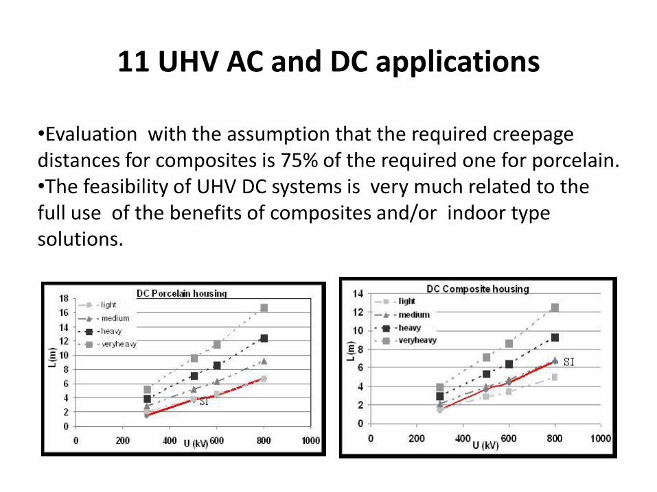
11 UHV AC and DC applications
•Evaluation with the assumption that the required creepage distances for composites is 75% of the required one for porcelain.•The feasibility of UHV DC systems is very much related to the full use of the benefits of composites and/or indoor type solutions.

11 UHV AC and DC applications
• Mechanical aspects related to UHV are also dealt with in this chapter of the brochure.
• Finally the need of Standards implementation to comply with UHV requirements are discussed in the brochure.

12 Conclusions
• Many thanks are due to all the WG Members participating to the development of the activity.
• Only a preliminary draft summary of the Brochure is reported in the presentation summary. The full results of the work carried out will be reported in the Brochure.


