Page 1
Universita degli studi di Padova
Dipartimento di Ingegneria dell’Informazione
Corso di Laurea Magistrale in
Ingegneria delle Telecomunicazioni
TESI DI LAUREA
A POPULARITY-BASED APPROACH
FOR THE DESIGN OF MOBILE
CONTENT DELIVERY NETWORKS
RELATORE: Prof. Michele Zorzi
CORRELATORI: Daniele Munaretto, Gerald Kunzmann
LAUREANDO: Daniele Romani
Padova, 14 ottobre 2013
Page 3
Misura cio che e misurabile,
e rendi misurabile cio che non lo e.
(Galileo Galilei)
Page 5
Sommario
Le Reti per la consegna di contenuti (CDN) sono progettate per supportare effi-
cacemente la fornitura di servizi multimediali continui e discreti ai consumatori.
La distribuzione dei contenuti su larga scala ad un costo ragionevole e senza
sovraccaricare la core network mobile e una scelta progettuale fondamentale per
gli operatori di rete. Al giorno d’oggi, un punto chiave e lo sviluppo di Reti mobili
per la consegna di contenuti (MCDN) efficienti dovuto principalmente all’aumento
giorno per giorno del volume di traffico video presente nella rete. In questa tesi
viene trattato un nuovo “approccio basato sulla popolarita” per la progettazione
e la realizzazione di MCDN. Per dimostrare queste funzionalita e stato imple-
mentato un vero e proprio testbed, con l’obiettivo di adattare flessibilmente il
caching video nella rete cellulare basandosi sulla dinamica degli utenti. Vengono
quindi discusse le possibili nuove sfide e fatte alcune considerazioni pratiche per
la distribuzione su larga scala in reti cellulari di nuova generazione.
v
Page 7
Abstract
Content Delivery Networks (CDNs) are designed to effectively support the deliv-
ery of continuous and discrete media to consumers. Enabling large scale content
distribution at a reasonable cost and without overloading the mobile core network
is a crucial design choice for Network Operators (NOs). Nowadays, a key task for
NOs is the development of efficient Mobile Content Delivery Networks (MCDNs)
due to the day-by-day increase of the video traffic volume in the network. In this
thesis, a novel “popularity-based approach” for the design and implementation of
MCDN is treated. To prove these functionalities, a real testbed is implemented,
with the target of flexibly adapting the video caching in the cellular network to
the users’ dynamics. New challenges are discussed and practical considerations
are drawn for wide-scale deployment in next generation cellular networks.
vii
Page 9
Contents
Sommario v
Abstract vii
1 Introduction 1
2 Delivery architecture 5
2.1 Functional requirements . . . . . . . . . . . . . . . . . . . . . . . 5
2.2 Technical approach . . . . . . . . . . . . . . . . . . . . . . . . . . 7
2.2.1 Functional architecture . . . . . . . . . . . . . . . . . . . . 7
2.2.2 Transport Optimization subsystem: details . . . . . . . . . 9
TO modules . . . . . . . . . . . . . . . . . . . . . . . . . . . . . . 9
CDN modules . . . . . . . . . . . . . . . . . . . . . . . . . . . . . 10
2.3 MEDIEVAL network topology . . . . . . . . . . . . . . . . . . . . 12
3 MCDN architecture: a popularity-based approach 13
3.1 Reference Technologies and Challenges . . . . . . . . . . . . . . . 13
3.1.1 Mobile Content Distribution Networks . . . . . . . . . . . 13
3.1.2 Quality of Service (QoS) and Quality of Experience (QoE) 14
3.2 CDN component: architecture . . . . . . . . . . . . . . . . . . . . 15
3.2.1 Decision Module (DM) . . . . . . . . . . . . . . . . . . . . 17
3.2.2 CDN Node Control (CDNNC) . . . . . . . . . . . . . . . . 17
3.2.3 Application monitoring (AM) . . . . . . . . . . . . . . . . 18
3.3 MEDIEVAL: physical placement of nodes . . . . . . . . . . . . . . 18
3.4 MCDN System . . . . . . . . . . . . . . . . . . . . . . . . . . . . 19
3.4.1 Entities . . . . . . . . . . . . . . . . . . . . . . . . . . . . 19
3.4.2 Features . . . . . . . . . . . . . . . . . . . . . . . . . . . . 22
ix
Page 10
4 Implementation of the MCDN 24
4.1 Technological requirements . . . . . . . . . . . . . . . . . . . . . . 24
4.2 System features: implementation . . . . . . . . . . . . . . . . . . 26
4.2.1 Node . . . . . . . . . . . . . . . . . . . . . . . . . . . . . . 26
Popularity Management . . . . . . . . . . . . . . . . . . . . . . . 28
Request Routing Management . . . . . . . . . . . . . . . . . . . . 29
4.2.2 Core Router . . . . . . . . . . . . . . . . . . . . . . . . . . 30
Popularity Management . . . . . . . . . . . . . . . . . . . . . . . 32
Request Routing Management . . . . . . . . . . . . . . . . . . . . 36
4.2.3 Origin . . . . . . . . . . . . . . . . . . . . . . . . . . . . . 38
4.2.4 Portal . . . . . . . . . . . . . . . . . . . . . . . . . . . . . 39
5 Simulation work and real testbed implementation 44
5.1 Mobile CDN: Simulation work . . . . . . . . . . . . . . . . . . . . 44
5.1.1 Regional and global popularity . . . . . . . . . . . . . . . 44
5.1.2 Generation of regional and global popularity . . . . . . . . 46
5.1.3 Optimal cache dimensioning for MCDNs: cost model . . . 51
5.2 Real testbed implementation . . . . . . . . . . . . . . . . . . . . . 57
6 Results 60
6.1 Popularity-based caching and distributed request routing . . . . . 60
6.1.1 Testbed: simulator of requests . . . . . . . . . . . . . . . . 62
6.1.2 Real scenarios: analysis . . . . . . . . . . . . . . . . . . . . 66
6.1.3 Simulations results . . . . . . . . . . . . . . . . . . . . . . 68
6.2 Features of the real system . . . . . . . . . . . . . . . . . . . . . . 76
6.2.1 Segmented videos and request routing . . . . . . . . . . . . 76
6.2.2 Robustness of CDN component . . . . . . . . . . . . . . . 77
6.2.3 Session continuity during handovers . . . . . . . . . . . . . 78
7 Conclusions 81
Bibliography 85
x
Page 11
List of Abbreviations
ALTO Application-Layer Traffic Optimisation
AM Application Manager (component / module)
AN Access Network
CDN Content Delivery Network (component / module)
CDNNC CDN Node Control (component / module)
CN Core Network
CNM Core Network Monitoring (component / module)
DASH Dynamic Adaptive Streaming over HTTP
DM Decision Manager (component / module)
DMM Distributed Mobility Management
FM Flow Manager (component / module)
HA Home Agent
HoA Home Address
HTTP Hypertext Transfer Protocol
IEEE The Institute of Electrical and Electronics Engineers
IETF The Internet Engineering Task Force
IP Internet Protocol
LMA Local Mobility Anchor
LTE Long Term Evolution
MAC Medium Access Control
MAG Mobile Access Gateway
MAR Mobile Access Router
xi
Page 12
MCDN Mobile Content Delivery Network
MEDIEVAL MultimEDia transport for mobIlE Video AppLications
MPD Media Presentation Description
MM Mobility Management (component / module)
MN Mobile Node
MPEG Moving Picture Experts Group
NAT Network Address Translation
NO Network Operator
PoA Point of Attachment
P-GW Packet Data Network Gateway
QoE Quality of Experience
QoS Quality of Service
S-GW Serving Gateway
TE Traffic Engineering (component / module)
TO Transport Optimisation (component / module)
UMTS Universal Mobile Telecommunications System
URL Uniform Resource Locator
VoD Video on Demand
VoIP Voice over IP
VSC Video Service Control (component / module)
WA Wireless Access (component / module)
WLAN Wireless Lan
XLO Cross-Layer Optimisation (module)
xii
Page 13
List of Figures
2.1 MEDIEVAL system: Mobile Video Delivery network . . . . . . . 6
2.2 MEDIEVAL Global Architecture . . . . . . . . . . . . . . . . . . 8
2.3 Transport Optimization subsystem . . . . . . . . . . . . . . . . . 9
2.4 CDN component: modules and interfaces . . . . . . . . . . . . . . 11
2.5 MEDIEVAL system: global structure . . . . . . . . . . . . . . . . 12
3.1 CDN component . . . . . . . . . . . . . . . . . . . . . . . . . . . 16
3.2 Physical placement of the MEDIEVAL entities . . . . . . . . . . . 18
3.3 MCDN software structure. . . . . . . . . . . . . . . . . . . . . . . 20
4.1 MCDN software structure. . . . . . . . . . . . . . . . . . . . . . . 26
4.2 Node: Apache and Squid servers, network and popularity databases. 27
4.3 Node: details of local popularity database . . . . . . . . . . . . . 28
4.4 Core Router: popularity and network databases. . . . . . . . . . . 30
4.5 Core Router: details of main popularity database . . . . . . . . . 31
4.6 Core Router: details of network information database . . . . . . . 32
4.7 Popularity management. . . . . . . . . . . . . . . . . . . . . . . . 35
4.8 Request Routing management. . . . . . . . . . . . . . . . . . . . . 37
4.9 Origin: Apache server and network database. . . . . . . . . . . . . 38
4.10 Portal: homepage site. . . . . . . . . . . . . . . . . . . . . . . . . 40
4.11 Portal: player page, with video description and VLC-player em-
bedded. . . . . . . . . . . . . . . . . . . . . . . . . . . . . . . . . 41
4.12 Portal: popularity simulator page, with the available settings. . . 42
4.13 Portal: network configuration page, with the available settings. . . 43
5.1 Rank-Frequency-Plot of the Top 100 music charts in 15 European
countries. . . . . . . . . . . . . . . . . . . . . . . . . . . . . . . . 45
5.2 Number of songs being popular in X out of 15 regions. . . . . . . 45
xiii
Page 14
5.3 Number of globally popular items at different thresholds to con-
sider content as globally popular. . . . . . . . . . . . . . . . . . . 46
5.4 Local popularity generation: theoretical model. . . . . . . . . . . 47
5.5 Rank correlation of the different regions. . . . . . . . . . . . . . . 50
5.6 MCDN network topology: cost model. . . . . . . . . . . . . . . . 52
5.7 Real testbed architecture. . . . . . . . . . . . . . . . . . . . . . . 58
6.1 Testbed: GUI of the request generator. . . . . . . . . . . . . . . . 63
6.2 GUI showing the content in Node. . . . . . . . . . . . . . . . . . . 64
6.3 Simplified cost model used to optimize the total cost. . . . . . . . 68
6.4 Scenario 1: Sum of traffic volume between entities. . . . . . . . . 71
6.5 Scenario 1: Cache size on Number of request/region. . . . . . . . 71
6.6 Scenario 2: Total cost in the Core Network. . . . . . . . . . . . . 73
6.7 Scenario 2: Cost minimization of CDN system: percentage of the
costs on system without CDN functionalities. . . . . . . . . . . . 74
xiv
Page 15
List of Tables
3.1 MOS values and their QoE levels . . . . . . . . . . . . . . . . . . 15
6.1 Simulation: Scenario 1 - Results . . . . . . . . . . . . . . . . . . . 70
6.2 Simulation: Scenario 2 - results with N. of request/region = 1000 75
6.3 Simulation: Scenario 2 - results with N. of request/region = 5000 75
6.4 Scenario 2: percentage of total cost of CDN system on total cost
of NO-CDN system . . . . . . . . . . . . . . . . . . . . . . . . . 76
xv
Page 16
Chapter 1
Introduction
Internet traffic has increased steeply in recent years, mainly due to the fruition
of video and others streaming contents, social platforms (with embedded video
players) and peer-to-peer networks. In addition, the quick penetration of hand-
held devices equipped with multiple ways of access to Internet, mainly 3G, WiFi
and a LTE, suggests that wireless access represents an ever-growing portion of
current and future demand with the users’ expectation of an “anywhere, any-
time” connectivity, thus encouraging operators to investigate and deploy different
combinations of wireless access technologies with the purpose of reducing their
operational costs.The increasing demand of mobile data services from users is no
longer a threat to operators, but a reality that now needs be analysed and dealt
with. Video traffic represents almost 90% of the consumer traffic and has become
a major challenge for the future Internet.
However, the current Mobile Internet is not designed for video and its archi-
tecture is very inefficient when handling video traffic. The idea is that the future
Internet architecture should be tailored to efficiently support the requirements of
this traffic. Specific mechanisms for video should be introduced at all layers of
the protocol stack for enhancing the efficiency of video transport and delivery,
that can increased, besides Quality of Service (QoS), a new concept of quality
called Quality of Experience (QoE) to the final user.
Mobile operators have to face these problems taking into account the fact that
the proposed solutions have to be also compatible within the existing mobile
network. To address this problem, a set of mechanisms that individually pro-
vide enhancements in the efficiency of video transport while cumulatively ex-
1
Page 17
ploiting their cross-layer functionalities to boost performance. These mechanisms
include enhanced wireless support (with general abstractions to address heteroge-
neous wireless technologies), improved mobility (to allow opportunistic handovers
across technologies), improved video distribution (with embedded caches in the
network), and flexible video service provisioning and control (exploiting the in-
teraction with video applications). Morover, these enhancements can potentially
be incorporated separately to future cellular networks.
In particular our focus is on the transport optimization aspects regarding
principally the video distribution and secondly the mobility management. We
study critical aspects to be tackled and we propose a solution which involves the
negotiation of resource allocation at the wireless access and implements optimal
handover decisions based on the mobility module. MCDN is designed to enhance
video transport via caching strategies specifically designed for improving the video
performance and takes into account the environment of the entire system. MCDN
integrates mobile delivery services that optimize the transport of several contents
including live video streaming, video on demand and delivery of content assets.
The purpose of our work is to design and to implement a MCDN tailored to the
challenging world of the mobile video traffic over next generation cellular networks
reminding that the technology developed takes into account the requirements of
NOs for commercial deployment improves the QoE of the final users as well
as reduces the costs for mobile operators. Moreover, the studied technology is
implemented in a testbed that serves as a proof of concept as well as a basis for
future commercial deployments.
The structure of the thesis is as follows:
• Chapter 2 provides a short summary on the reference model of our mobile
video delivery system.
• Chapter 3 describes the study and the design of a mobile CDN (MCDN)
concept for efficient media delivery based on intelligent caching with the
integration of the standard video technology MPEG-DASH.
• Chapter 4 presents how the system is implemented.
• Chapter 5 shows some studies on popularity aspects and introduces a con-
tent popularity model to evaluate the CDN component, which is then im-
2
Page 18
plemented in a simulator. Finally, we described a practical scenario imple-
mented in a real testbed.
• Chapter 6 gives some results about the performance of our simulations.
• Chapter 7 concludes the thesis.
3
Page 20
Chapter 2
Delivery architecture
The reference model of our mobile video delivery system is taken from the Eu-
ropean project MEDIEVAL [1]. MEDIEVAL (MultiMEDia transport for mo-
bIlE Video AppLications) is a small or medium-scale focused research project
(STREP) of the 7th Framework Programme [2] of the European Commission [3],
addressing the core of the strategic objective “The Network of the Future”. ME-
DIEVAL aims at evolving the Internet architecture for efficient video transport,
following a cross-layer design. The Figure 2.1 shows MEDIEVAL’s vision of the
future Internet architecture that should be tailored to efficiently support the re-
quirements of video traffic.
In particular, the technology studied and developed by this work will be designed
taking into account the requirements of network operators for commercial deploy-
ment, and will aim at improving the Quality of Experience by users as well as
reducing the costs for operators by exploiting Content Delivery Networks (CDNs)
techniques adapted for the mobile environment and managed by a popularity-
based approach.
2.1 Functional requirements
The MEDIEVAL services refer to a list of challenging user services which are
expected to dominate the traffic over the wireless networks in the near future. In
particular, as you can see in Figure 2.1, the main typologies of video traffic will be
the following: Personal Broadcast, MobileTV, Mobile Video on Demand (VoD)
5
Page 21
Technical ApproachThe key components of the MEDIEVAL architecture are illustrated in the figure on the right. The proposed architecture comprises the following five key functionalities: • Interaction with the underlying network
mechanisms to allow video services optimally customise the network behaviour.
• Enhanced wireless access to optimise video performance by exploiting the features of each available wireless technology.
• Novel dynamic mobility architecture for next generation mobile networks adapted to video service requirements.
• Optimisation of the video transport by means of Quality of Experience driven network mechanisms, including caching and network support for P2P video streaming.
• Support for broadcast and multicast video services by introducing multicast mechanisms at different layers of the protocol stack.
LTE
Internet
LTEWLAN
LocalGateway
LocalGateway
Mobile Network Provider
VideoContent & Services
Other MobileNetwork Providers
Internet TV
PersonalBroadcasting
localmobility
globalmobility
Multimodeterminal
Video onDemand
Interactivevideo
VideoContent & Services
Content Provider
MEDIEVAL vision
Key Issues The proposed architecture will address the following five key issues: • Specification of an interface between the
video services and the underlying network mechanisms.
• Enhanced wireless access to optimise video performance.
• Design of a novel dynamic mobility architecture adapted to video service requirements.
• Optimisation of the video delivery by means of Quality of Experience (QoE) driven network mechanisms.
• Support for broadcast and multicast video services, including Internet TV and Personal Broadcasting.
Expected Impact Video services are a very promising business case. One key goal of the project is to propose an operator-driven architecture, resulting in an integrated video solution that can be implemented by an operator and offered to its customers. The research conducted in MEDIEVAL will also aim at strengthening current mobile core and video solutions, resulting in both IPR generation (when applicable) as well as dissemination of these results in prestigious scientific fora. The project will follow and contribute to the main standardisation bodies such as 3GPP, IETF and IEEE, which have already detected the need for video enhancements.
MEDIEVAL October 2010
Figure 2.1: MEDIEVAL system: Mobile Video Delivery network
and Interactive Video. These services drive the main goal of the project, which
consists in designing a video-aware transport architecture suitable for commer-
cial deployment by mobile network operators. The proposed architecture aims
at including video specific enhancements at each layer of the protocol stack to
provide better video support at a lower exploration cost. This key point of the
project is achieved based on the following requirements:
• Improve the user experience by allowing the video services to optimally
customize the network behaviour;
• Optimize the video performance by enhancing the features of the available
wireless accesses in coordination with the video services;
• Design a novel dynamic architecture for next generation mobile networks
tailored to the proposed video services;
• Perform a transport optimization of the video by means of QoE driven
network mechanisms, including MCDN techniques, which represent the core
of this work;
• Introduce multicast mechanisms at different layers of the protocol stack to
provide both broadcast and multicast video services, including Mobile
6
Page 22
TV and Personal Broadcast.
2.2 Technical approach
The purpose of this section is to introduce the architecture design of the ME-
DIEVAL Transport Optimization subsystem. In the design of this subsystem,
the idea is a novel dynamic transport architecture for next generation mobile
networks that is adapted to video service requirements. The plan is to follow
a QoE-oriented redesign of networking mechanisms as well as the integration of
Content Delivery Networks (CDN) techniques with a popularity-based approach.
2.2.1 Functional architecture
First of all, we introduce a brief description of four subsystems placed in the
global architecture of MEDIEVAL system1. This is depicted Figure 2.2:
• Video Services Control (VSC). The aim of this is to provide the link between
video applications and the core network mechanisms by using enablers that
permit to communicate with the rest of the architecture;
• Wireless Access (WA). The performance of the video delivery can be op-
timized in the wireless access by exploiting the specific features of the dif-
ferent underlying wireless technologies; in particular defines a solution to
provide multiple accesses at the last hop, mainly focusing on a novel joint
abstract level, i.e., IEEE 802.11. Due to the mobility of the users a mobil-
ity management component is designed to perform the handovers between
different points of access, without loosing the session continuity, i.e., using
Distributed Mobility Management (DMM) functions [5, 6];
• Mobility Management (MM). Global reachability and session continuity
of mobile terminals are provided by mobile IP-like solutions, which have
proved to be hard to deploy and operate. For video services, global reacha-
bility is not critical, since initial reachability can be managed at the appli-
cation level;
1More details about all subsystem can be found in [4].
7
Page 23
• Transport Optimization (TO). The MEDIEVAL architecture design aims
at controlling resources of the operator network. To maximise the per-
ceived quality (QoE) experienced by video users in the wireless link the
transport optimization module performs a negotiation of the resource al-
locations within the wireless access and takes optimal handover decisions
by interacting with the mobility module. Moreover, CDN-based techniques
will be also designed to further enhance video transport, including caching
specifically designed for video performance.
Figure 2.2: MEDIEVAL Global Architecture
8
Page 24
2.2.2 Transport Optimization subsystem: details
Figure 2.3 shows the architecture of the Transport Optimisation subsystem [7]
composed of two main components CDN (CDN) and Transport Optimisation
(TO). In this section we give a short wrap-up about the components and their
functionalities and how they interact with Mobility Management, Wireless Access
and Video Services. In particular, the CDN component functionality and the
interaction/cooperation between the sub-modules inside are the main effort of
the work in this thesis.
Figure 2.3: Transport Optimization subsystem
TO modules2
The modules of the TO component form a feedback loop between the Cross-
layer Optimisation module and the Traffic Engineering module. The TO aims at
optimising the user perceived quality, while trying to reduce the traffic in the core
network and avoid congestion in the access. It is limited by the physical capacity
of the wireless links.
• Cross-layer Optimisation (XLO): is triggered by events in the network and
cooperates with TE and other layers to address these issues. Triggers are
2More details are provided in [7]
9
Page 25
mainly due to congestion in the PoA (Point of Attachment) or inside the
network (detected by CNM), or low quality observed by the end-to-end mon-
itoring in the Video Services subsystem. Having access to various metrics
and (cross-layer) information from other modules, the different algorithms
in the XLO try to address and solve the problems in different dimensions
(time, granularity, scope) and levels (access, network, service);
• Traffic Engineering (TE): is the entity which executes actions within the
network dictated by the XLO. These actions include layer filtering, video
frame dropping, video frame scheduling, transcoding, and application-layer
FEC adaptation;
• Core Network Monitoring module (CNM): is monitoring the status of the
mobile network, and providing this information to Video Services subsystem
when needed. Commercial solutions already exist that provide the required
set of monitoring functionalities.
CDN modules3
The modules of the CDN component (Figure 2.4, taken from [8]) provide and
manage a set of in-network CDN nodes caching the most popular content. The
enclosing CDN modules are responsible to maintain an optimal content placement
inside these caches and perform request routing to forward user requests to the
most appropriate CDN node. The request routing thereby not only considers
availability of content in the local cache, but also takes into account other criteria
and policies specified by the network operator. Interfaces with the Video Service
Portal and the Mobility subsystem support the setup of multimedia streams and
allow for optimised handover decisions.
• Decision Module (DM): acts as the main intelligence of the CDN compo-
nent. It makes all decisions concerning request routing, content and service
placement, resource management, and handover optimisation. It uses pop-
ularity information for make decision about content displacement;
• CDN Node Control (CDNNC): is the mediator between the DM and the
actual CDN Nodes. As such, it is responsible to monitor and manage
3More details are provided in [8]
10
Page 26
Figure 2.4: CDN component: modules and interfaces
CDN Nodes and the content stored inside. Its operations include content
management (e.g. store/delete requests, replication, recovery) and node
monitoring and maintenance;
• Application Monitoring (AM): is a database-like component monitoring the
popularity of content items in the different regions of the network. It sup-
ports the content placement decisions of the DM.
11
Page 27
2.3 MEDIEVAL network topology
Here we provide the global structure of the MEDIEVAL system. In Figure 2.5
[4], the typical MEDIEVAL network topology is given, where the main nodes are
the Mobile Nodes, the Mobility Access Router (MAR), the Point of Attachment
(PoA) (WLAN, UMTS and LTE-A are the wireless access technologies consid-
ered), the mobile MAR (mMAR), the Core Routers and the CDN nodes.
Administrative Domain 2
Administrative Domain 1
PoA
PoA
PoA
PoA LTE
MAR
LTEWLANPoA
MAR
PoA
PoAPoA
PoAPoA
Local Mobility Domain 2
CDN
CDN
PoA
PoA
PoA
PoALTE
MAR
LTE WLANPoA
MAR
PoA
PoA PoA
PoA PoA
Local Mobility Domain
MN
MN
Internet
Video Content & ServicesContent Providers
CDN
CDN
mMAR
mMAR
Over The Top (OTT) Video Servers
Personal Broadcasters
Network Transport
Core Router
Core Router
CDN node
CDN node
CDN node
CDN node
ISP Video Server
ALTO ServerMIIS ServerSessionManagement
ProvisioningPlatform
Video Service Portal
MN
Core Router
Core Router
Core Router
MN
MN
PBS (multicast traffic)
Figure 2.5: MEDIEVAL system: global structure
12
Page 28
Chapter 3
MCDN architecture: a
popularity-based approach
We study and design of a mobile CDN (MCDN) for efficient media delivery based
on intelligent caching, in contrast to existing solutions that rely on information
provided by the network for optimal source (cache) selection and on any kind of
network access from the final user. The decision about which content to store
in the CDN nodes (i.e., the replacement strategy) is based on the popularity of
videos considering the different regions of the network. For these reasons we can
talk about MCDN with a popularity based approach. Afterwards, a new standard
video technology MPEG-DASH (ISO/IEC 23009-1) is integrated in the system.
3.1 Reference Technologies and Challenges
3.1.1 Mobile Content Distribution Networks
Mobile Content Distribution Networks (MCDNs) are used to manage the distri-
bution of content in the network optimizing the delivery to end users on any type
of access network. As for traditional CDNs, MCDNs can reduce the traffic in the
network (thereby also reducing network congestion) by caching popular content
close to the users. Moreover, by locating the CDN servers close to the users, fast
and reliable applications and services can be offered to the users. CDN networks
are more than just pure network caches, but they also support content routing
and accounting. They can also improve access to content that is typically un-
cacheable by caching proxies, including secured content, streaming content and
13
Page 29
dynamic content. In general, CDNs improve the scalability of service by reducing
the origin server load. In the MEDIEVAL project the CDN component provides
a MCDN solution where we aim at improving cooperative cache management
algorithms in order to maximize the traffic volume served from the local cache
and minimize the costs in the overall network. Thereby, costs can be represent
by monetary expenses (e.g. for deploying the caches), as well as other metrics
like management overhead or network congestion. Moreover, in contrast to Web-
oriented CDNs, setting up a CDN network inside a mobile operator network puts
different requirements on the decision where to place the CDN nodes, as mobile
specific network architectures and protocols must be considered.
3.1.2 Quality of Service (QoS) and Quality of Experience
(QoE)
QoS represents a combination of several objective attributes of services, typically
the bitrate, delay, error ratio, etc. There has been a common belief that by im-
proving QoS (Quality of Service) the operators could provide high level of quality
to users. In recent years this thinking has evolved to the concept of QoE (Quality
of Experience). Rather than the performance statistics of the service, QoE con-
cerns more the user experience impacted by the service performance. Especially
for video applications, experience of the application is more sensitive and has
more dimensions compared to traditional applications. For video applications,
which are the focus in the MEDIEVAL project, there could be a broad defini-
tion of QoE, covering all aspects of a video application, e.g., satisfaction of video
quality, user interfaces, devices, etc. In the MEDIEVAL project we will refer to
the perceptual quality of videos impacted by the video delivery chain as QoE.
As an original video is subject to several impairments during the delivery, the
video quality perceived by users is degraded. The quality of impaired videos can
be measured by performing subjective tests, in which subjects are asked to rate
the videos. However this kind of methods is not feasible in service and network
development work. Objective video quality assessment methods are therefore
extensively developed to be applied in multiple scenarios where the perceptual
quality of videos is demanded without performing time-consuming subjective test.
Based on the type of input data being used for perceptual quality assessment,
the objective video quality assessment methods can be classified into several cat-
14
Page 30
MOS Perceptual quality
5 Excellent
4 Good
3 Fair
2 Poor
1 Bad
Table 3.1: MOS values and their QoE levels
egories. One of them, that is widely used, is a media-layer method analysing
video signals to assess QoE. The perceptual quality of videos is rated numerically
by MOS (Mean Opinion Score) levels, see Table 3.1. Comparing the MOS lev-
els rated by subjects and computed by the aforementioned objective assessment
methods, the performance of the objective assessment can be evaluated. Given an
objective QoE assessment method, network optimizers are able to perform their
decision making by taking into account the impact on resulted QoE. QoE-based
optimization allows operators to maintain user satisfaction when deciding on the
policy and managing their traffic.
3.2 CDN component: architecture
As we said in section 2.2.2, the Transport Optimization subsystem is composed
of two main components providing CDN mechanisms for video streaming as well
as cross-layer transport optimization. In particular, this thesis discuss the design
and implementation of CDN component to provide a mobile CDN solution for
video delivery including network based caching, network guided optimisation of
content delivery and advanced multicast solutions. This includes maintaining an
efficient and stable overlay topology for the control and management of the CDN
nodes, performing load balancing among the video sources and network elements,
selecting optimal content locations as well as relaying connections for mobility,
caching, or confidentially reasons. This requires a continuous monitoring of the
current conditions of the entire system, in particular the status and distribution
of the CDN nodes, as well as the popularity of content. Using the collected data it
will dynamically maintain an optimal configuration of a set of servers for content
15
Page 31
distribution and select optimal sources for transmitting the video to the user.
Summarizing, the CDN component is used to:
• Provide a mobile CDN solution for video delivery including network based
caching, peer-to-peer mechanisms, and advanced multicast solutions.
• Dynamically maintain an optimal configuration of a set of servers for con-
tent distribution with respect to the current conditions of the entire system.
• Appropriately select content locations to save network resources, inter-
domain traffic and delivery delay.
• Coordinate with the Mobility subsystem to achieve handover optimization
and QoE optimization.
Figure 3.1: CDN component
Moreover, CDN component drives optimization at several stages of content
handling:
• Pro-active off-line placement of content in the CDN nodes;
• On-line network guided selection of content locations from which to down-
load;
• On-line download and placement of contents in CDN nodes;
• Multicast content delivery and Relay-assisted delivery.
16
Page 32
As shown in Figure 3.1, the CDN component consists of three modules that we
show more in deep in the next sections.
3.2.1 Decision Module (DM)
The decision module (DM) is the central module of the CDN component. It is
part of the session initiation and handover preparations. It decides when and
where to store content in the CDN nodes, based on the popularity of the video
files. During the session initiation, the DM also informs the mobile client about
which source should be used for streaming/downloading the content, e.g. from
either the (external) content provider or a cached copy from one of the CDN
nodes. Based on the information from the application monitoring module (AM)
and the CDN Node Control (CDNNC), the decision module will decide on which
storage location should be selected as the optimal source for transmitting the
video to the user. Particularly the DM and the CDNNC need to be closely
coordinated. While the DM is responsible for content placement with respect to
resource requests (content popularity, etc.), the CDNNC is responsible for CDN
maintenance and may need to relocate content for this purpose.
3.2.2 CDN Node Control (CDNNC)
The CDN node control module (CDNNC) is responsible for management and con-
trol of the operations of the CDN nodes. It is responsible for maintaining CDN
related status information such as the current load, (free) capacities, and informa-
tion about stored content. This information is provided to the decision module.
The CDNNC will also receive commands from the decision module requesting it
to store, move, replicate, or delete content, based on the changing popularity of
content, the mobility of users or user groups, or congestion in certain parts of
the core or access network that may require shifting flows and content to less
congested parts of the network.
This requires a close interworking between the decision module and the control
module. The CDNNC module has (internal) interfaces to the actual CDN nodes,
and an interface to the decision module. If the CDN is merely used for caching,
but content can always be reliably retrieved from the original server, CDN re-
silience is of less concern.
17
Page 33
3.2.3 Application monitoring (AM)
The application monitoring module (AM) receives input from the decision module
about the request rate of certain videos. This information is used to calculate
the popularity of the videos. This popularity data is necessary for the decision
block to optimize the content placement.
3.3 MEDIEVAL: physical placement of nodes
The following figure (3.2) and list shows the physical placement of the functional
entities in MEDIEVAL vision, see [9].
Figure 3.2: Physical placement of the MEDIEVAL entities
18
Page 34
• Decision module:
- Dedicated server in core network (including the central ALTO1 information
server), or attached to the MAR (P-GW or PCRF) with a central ALTO
information server;
• CDN node control:
- Attached to the MAR (P-GW);
• Application Monitoring in CDN nodes:
- Attached to the MAR (P-GW, S-GW).
The MEDIEVAL model with the specific requirements are the starting point of
the design and implementation of MCDN that we discuss in section 3.4.
3.4 MCDN System
With reference to the previous section, now we describe the architecture imple-
mented in the software managing of MCDN; in particular the main entities with
their features and functionalities. The development of the software, following the
specifications required by the MEDIEVAL system is the real result of our efforts
for this thesis.
3.4.1 Entities
Since mobile core networks are usually hierarchical, i.e., with a central core part as
well as branches and leaves in different regions of a deployment area, for example
a country, the MCDN software has a hierarchical structure too. Thus, four main
entities builds the overall structure, as you can see in Figure 4.1:
1. Core Router, is the principal entity, where is located almost the entire
intelligence of the system; it provides the functionalities of the CDN com-
ponent defined before (see 2.4): DM, CDNNC and AM.
1ALTO (Application-Layer Traffic Optimisation) [10] module, provides a database contain-
ing network status characteristics. In our work, we don’t implement the functionalities of this
module.
19
Page 35
Figure 3.3: MCDN software structure.
The functions that it performs are:
• CDN cache managing:
– checks for local information databases provided by the Nodes;
– analyzes the received databases;
– updates the main internal database;
– makes decision on delivering, deleting and maintaining contents
in local Nodes cache relying on a policy based on the popularity
of content, in particular the number of views of video2.
• Request Routing:
If the user’s request is not deployable directly to the Node (content no
in the local cache), this is forwarded to Core Router:
2In the next Chapter, we will introduce a new concept of popularity no longer based on the
views of a video but but rather on the views of the video chunks, using a new standard called
MPEG-DASH.
20
Page 36
– it computes the best-path3 to serve the request choosing another
Node or directly the Origin/Source;
– then, it sends the address of the best location to the Node to serve
the client request.
The first functionalities of cache managing are performed off-line while the
second of request routing, every time the Nodes require a content not in
local cache.
2. Node, positioned at the edge of the network, close to PoA. This entity have
both caching and proxy-server functionalities installed:
• Caching content:
– this function is driven through commands sent by the DM (through
the CDNNC module) about the data to be stored, delete or mod-
ify;
– after the command, the Node take action to fixes up the internal
cache (i.e., requests to the Core Router and/or deletes in local
cache).
• Request Routing:
– if the user’s request can be performed directly from the local cache
the request does not travel through the Core Network;
– in the other case, if the request routing can not be done by Node
(i.e., the content is not stored locally), it must contact DM to
obtain the routing information to obtain the resource.
• Update local database:
– this is simply the number of requests, for a certain content, that
reach a Node in a given time interval (settable). This information
is stored in the local database, that is uploaded into the Core
Router. Every time a content is required the counter of number
of requests is increased.
We can observe that due to the nature of the MCDN it is clear that the
popularity is obtained at the edge of the network, and we can talking
about local popularity.
3The policies of best-routing will be discuss in the next Chapter.
21
Page 37
3. Origin, that is the entity where the original contents are stored, and is
positioned inside the Core Network. This is the main cache of the system:
• Storing content
– gives access to the stored contents and provides to the Nodes the
possibility to get the contents to be stored in the local caches.
The location of the Origin impacts the performance of the overall
system, and, should be located at an equal distance from all the
local caches.
4. Portal, the entity through which the users can access the contents (via
Web Portal):
• Viewer of Available contents
– simple web page with video playing feature where the stored con-
tents in the Origin are shown and where the users can connect to
retrieve them;
• Simulator popularity request
– we can simulate the popularity behaviour of the videos and we
also set the network parameters (provided by ALTO) to test some
critical network configuration.
3.4.2 Features
The main general features of MCDN system are summarized here below, while
in Chapter 4 we analyse how to they are implemented and realized:
• Popularity-based caching
Since the system is mobile, a new concept of popularity is foreseen. The
caching is based on values of popularity, thus, a specific algorithm based on
these would be beneficial for the system;
• Request Routing
In our system this functionality is moved to the edge of the network. In
fact, most of CDN systems are based on a centralized request routing,
that means, a client, after a request, is redirected to the correct cache and
22
Page 38
this action is taken by a centralized entity. Thus, the problem is that the
signalling inside the Core Network increases while the purpose of our work
is minimize it;
• Robustness of the CDN component
In case of failures (e.g., Node fails or loses packets), the subsystem must
be able to react without introducing extra delay and without letting users
know about it. This aspect is very important since the users can be involved
in some failures, it is unavoidable, and following the QoE guidelines, they
should continue to use the service without knowing absolutely what has
happened;
• Session continuity during mobility
Is the ability of maintaining the session continuity during mobility of the
clients. In fact, the CDN module works also when a user moves from a PoA
to another PoA. Thus, we pay attention to the sessions opened during the
streaming and manage them during the handovers among different Nodes.
MPEG-DASH standard
Very important is the integration of MPEG-DASH4 standard in the system [11,
12, 13]; in particular, the request routing is made for a segment video and not
for whole video; then, the popularity-based caching is founded on the segment
requests. Thus, robustness and session continuity have better performance with
small chunks of video instead complete video. Also the memory space is better
managed.
4Dynamic Adaptive Streaming over HTTP where any multimedia file is divided into one or
more segmtens, and these are delivered to the client via HTTP (see Chapter 4).
23
Page 39
Chapter 4
Implementation of the MCDN
In this chapter we describe how the system is implemented. We analyze how the
entities of the system, described in the previous Chapter 3, work by defining the
implementation details and the proposed solutions.
4.1 Technological requirements
The entire system is IPv6-based since 1) it is the latest revision of the Internet
Protocol (IP) and 2) supports the mobility giving us the possibility to use the
DMM [5], implemented to manage the mobile handovers among different access
technologies (i.e. WiFi, 3G and LTE, etc).
The streaming services are based on the HTTP protocol and are independent
of media transport protocols such as Real Time Streaming Protocol (RTSP) or
Real Time Protocol (RTP). Thus, we can transport over HTTP any kind of file,
and the key aspect of this protocol is that it works well using proxies and mas-
querading features.
Moreover, the system is integrated with the standard MPEG-DASH (Dynamic
Adaptive Streaming over HTTP) [11, 12, 13] as video streaming protocol that is
an adaptive bitrate streaming technology where a multimedia file is partitioned
into one or more segments and delivered to a client using HTTP transport proto-
col. A media presentation description (MPD file) describes segment information
(timing, URL, media characteristics such as video resolution and bit rates). Seg-
24
Page 40
ments can contain any media data, however the specification provides guidance
and formats with two types of containers: MPEG-4 file format and MPEG-2
Transport Stream. One or more representations (i.e., versions at different resolu-
tions or bit rates) of multimedia files are available, and the selection can be made
based on the current network conditions, device capabilities and user preferences.
DASH is agnostic of the underlying application layer protocol. [14, 15, 16]
Exploiting the HTTP protocol, a simple Proxy Web Server for the proxy
functionalities and simple Web Server for caching are used. In particular, in our
system we use Squid proxy server [18, 19] and Apache web server [17].
Squid in an open-source proxy server able also to do web caching. It has a
wide variety of uses, from speeding up a web server by caching repeated requests,
to caching web, DNS and other computer network lookups for a group of people
sharing network resources and to aiding security by filtering traffic.
The Apache HTTP server, commonly referred to as Apache, is a web server
software program notable for playing a key role in the initial growth of the World
Wide Web. Apache supports a variety of features implemented as compiled mod-
ules which extend the core functionality. These can range from server-side pro-
gramming language support to authentication schemes. Some common language
interfaces support Perl, Python and PHP.
The functionalities of the framework are mainly written in Perl [20], that is
an high-level, general-purpose, interpreted and dynamic programming language.
It is well supported by Apache web server and Squid proxy server.
Moreover, the testbed is prepared with machines Unix system (in particular Linux
Ubuntu v10.04).
To communicate popularity information, we use a simple customized database
system based on text files and not a Database Management System.1 Besides
this popularity database, there are also the network information database on the
Nodes and in the Core Router.
1Database Management System (DBMS) is a software system designed to allow the defini-
tion, creation, querying, update, and administration of databases
25
Page 41
4.2 System features: implementation
In this section, we analyse the details of each entity deployed in our system. We
present, for everyone, the software structure with a short description of the specific
blocks and how they work. We remember that every block is implemented in Perl
language and inside each entity there is a configuration file (.pm), through which
we let the entities gather information such as IP addresses (to be communicated)
and paths of databases (to let scripts reach them). There are also some tuning
parameters, such as time interval between uploads for databases in the Nodes
and time interval between maintenance actions for the main database in the
Core Router. For the sake of clarity, we represent the Figure 4.1 proposed in
section 3.4.
Figure 4.1: MCDN software structure.
4.2.1 Node
As depicted in the Figure 4.2, the Node, that is located in the edge of network
close to the PoA, is responsible of the functionalities of content caching and Proxy
server. This entity works transparently to the end-user; it intercepts and manages
all the requests passing through it. Two distinct roles has the Node:
1. management of local cache supervised by Core Router; in particular it re-
ceives commands from CDNNC module;
26
Page 42
2. proxy service that takes into account the mobility issues and leverages the
communication with the DMM system for the management of handovers
using a system of sophisticated networking rules.
Figure 4.2: Node: Apache and Squid servers, network and popularity databases.
The Node performs these function with four scripts:
• NodeConfig.pm
• whichServer.pl
• DBNodeUpload.pl
• serverMAR.pl.
Moreover, both Apache web server and Squid proxy server are used. There are
even local and network configuration databases stored in the Node that we de-
scribe later in this section.
By adopting the standard MPEG-DASH, see 4.1, where a multimedia file is
partitioned into one or more segments called chunks, the user downloads and
opens a Media Presentation Description (MPD) file through a video player (in
our case VLC [21]) that, in sequentially way, requires chunks and plays the video.
Each chunk is downloaded automatically via a simple single HTTP GET request.
27
Page 43
Before the description of operations performed in the Node, we explain how is
structured the local database, Figure 4.3,to manage the popularity and routing:
Figure 4.3: Node: details of local popularity database
The local database is named [IP−MAR] [FOOTPRINT ] FOOTPRINT MASK,
key for the uploading to the Core Router, where is recorded in unique way the IP
address of Node, IP-MAR, and the subnet served FOOTPRINT FOOTPRINT MASK;
- ID CONTENT is the unambiguous identification of the chunk in the Origin (i.e.,
http : //Origin cache path/name of video/name of chunck.m4s);
- NUMBER OF VIEWS is the field where we store the number of requests for
that chunk during a certain time interval, ∆T (e.g., [30, 60] s);
- AVAILABILITY, that is a flag (‘Y’ or ‘N’), is used to indicate if the content is
stored in the local cache or not; it is checked every ∆τ (e.g., fraction of ∆T);
- TLS (Time Last Seen), as even for the main database, takes into account also
the expiration of an entry, for the sake of maintenance.
Starting from the interception by Squid Proxy of the user request for a specific
video chunk, made in the begin of whichServer.pl that define the proxy rules, we
can split well the two main implementations of the capabilities of Node:
Popularity Management
1. open the local popularity database;
2. search of the entry associated to the requested chunk in the database:
• if is recorded, NUMBER OF VIEWS +1 and TLS update at actual
time;
• in the other case, record new entry with all information above.
3. close the local popularity database;
4. wait new client request through proxy interception;
28
Page 44
These operations are all made by proxy server using the rules defined in which-
Server.pl;
In the same temporal time, there is a second script, DBNodeUpload.pl, that
working in a timer way, manages the updating of content available directly from
the local cache and the forwarding of local database to the Core Router; summa-
rizing:
1. open the local popularity database;
2. check files inside local cache and update the AVAILABILITY in local database
(timing: ∆τ);
3. reorder of entities of local database based on decreasing values of NUMBER
OF VIEWS and delete the entry too old (old time is settable);
4. close the local popularity database;
5. upload the local database to Core Router;
6. after timeout event restart the script (timing: ∆T);
In the Node we can even find serverMAR.pl, through which the Core Router,
using the CDNNC module, informs the Node about actions to be taken, i.e.
storing and deleting chunks inside the local cache; these operations are performed
with the opening of Sockets. Moreover, a configuration file, NodeConfig.pm, holds
information about IP addresses, directory paths and some timers values;
Request Routing Management
Starting from the intercept of user’s request, for the request routing are made
these operations:
1. open local database for reading;
2. check the requested content inside the local cache:
• if it is stored, go directly to Node cache;
• else forward the request to Core Router (DM module) and wait the
address of best location to take the content (Origin cache or another
Node cache);
29
Page 45
3. close local database;
4. wait new client request through proxy interception;
4.2.2 Core Router
Core Router, the main entity of system (Figure 4.4), is responsible of function-
alities of managing local caches and request routing to find the best path. This
entity works in direct communication with local Nodes. Two main roles of Core
Router are:
Figure 4.4: Core Router: popularity and network databases.
1. management of local caches of Nodes; in particular DM module makes
decision and sends commands to CDNNC module;
2. calculate the best path (best-routing algorithm) to serve the content request
not deployable directly from local cache of Node.
The scripts that running in the Core Router are:
• DMConfig.pm
• DM.pl
• CDNNC pop.pl
• serverDM.pl.
30
Page 46
Before describing the functions, here below, we explain the central popularity
database, Figure 4.5, called even main or DBmain database and network infor-
mation database, Figure 4.6, called even DBNode:
Figure 4.5: Core Router: details of main popularity database
- ID CONTENT, is the unambiguous name of the content in the Origin as said
in previous section of the Node description;
- FOOTPRINT and the IP of the Node from which we received the popularity
values of that content;
ID CONTENT, FOOTPRINT and IP we can refer universally to a specific ele-
ment, and it can be considered a key in the database;
- AVAILABILITY, that is a flag (‘Y’ or ‘N’), to indicate if the content is stored
in the local cache or not.
The last fields are about the popularity values for the specific element;
- LAST-UPDATES, is an array composed of ten values, i.e., the number of re-
quests in a ∆T (time interval between two consecutive uploads), helpful to cal-
culate an universal value of popularity;
- TLS, is the Time Last Seen, to take into account also the expiration of an entry,
for the sake of maintenance;
- AVERAGE-POPULARITY is an average value among the chunk popularity
values to order the entries in the database.
31
Page 47
Now, we present the network information database, Figure 4.6:
Figure 4.6: Core Router: details of network information database
- IP-NODE FROM, IP address of reference Node;
- IP-NODE TO, IP address of compared Node;
- HOPS, distance in number of hops between reference and compare Nodes;
- LOAD, workload (in percent over maximum requests);
- MAX REQUESTS, number of maximum requests deployable;
- FP or ORIGIN, footprint (served subnet) or Origin entity;
- CACHE THRESHOLD, cache size in MB.
Popularity Management
This functionality is the most complex function of whole system and uses the
DM.pl and CDNNC.pl scripts; in particular the first regards the DM and AM
modules, responsible of optimize the content placement and decide where and
when store content in CDN Nodes, while the second, is responsible for commu-
nication, management and control of the operations on the CDN Node, i.e. it is
invoked by DM module.
In this entity, there is a special directory in charge of receiving local databases
from Nodes; in fact, as we said in Chapter 4.2.1, when a local timer expires, the
popularity database is sent to Core Router and reaches this folder.
Now, we can explain how is manage the popularity aspect in Core Router:
1. open, save in memory and close main database;
2. open network information database for reading;
3. check the active nodes to know the expected databases;
4. close network information database;
32
Page 48
5. for each active node:
(a) check the local database;
(b) open, save in memory and close local database;
(c) each local entry is searched in the main database:
• if there is, the main database is update: AVAILABILITY, LAST-
UPADTES, TLS and AVERAGE-POPULARITY2 are upgraded
and computed;
• else, a new entry is added;
(d) delete the local database analyzed;
6. delete the old entries in main database (this parameter, old-entry, is settable
and equal for all entities);
7. Cache Management: this operation is quite complex, so for the sake of clar-
ity is described below, in a separate section:
Cache Management
1. search the parameter CACHE THRESHOLD for analysed Node;
2. for each entry of the Node, where the flag AVAILABILITY is set to ‘N’ and
the content is not in the local cache:
(a) to know the cache status, call the subroutine free space in CDNNC pop.pl
with parameters IP MAR and CACHE THRESHOLD:
• if the cache is in status “CACHE FREE”, send directly the file to
the Node recall the subroutine send file in CDNNC pop.pl;
• else, while status is “CACHE BUSY”:
i. evaluate the rifPop of all contents stored in the Node (AVAIL-
ABILITY set to ‘Y’);
ii. delete the content, through the subroutine delelte file in CDNNC pop.pl,
with value less than the content of reference;
2Afterwards, we show the algorithm where is used this parameter.
33
Page 49
iii. if free memory in local cache is enough to store content, recall
the subroutine send file in CDNNC pop.pl;
(b) if there are entries still to be analyze, come back to 2.
Popularity value rifPop Algorithm
In order to evaluate the popularity value of the content we introduce an algo-
rithm; this is located in a subroutine in DM.pl and can be changed whenever a
new policy to manage the popularity is required.
To calculate this parameter, we treat two aspects:
• average value of views onto last 10 updates for the purpose of consider the
behaviour of “long period”;
• weighted moving average onto last 10 updates in order to attach more im-
portance to the last popularity values, i.e. the most currents;
So, we need the values of LAST-UPDATES in main database; now, is shown the
algorithm:
1. define of increasing values of weights (e.g. [0.05, 0.1, 0.15, 0.2, 0.25, 0.3, 0.4, 0.6, 0.65, 0.7]);
2. read the 10 values in LAST-UPDATES;
3. calculate the normal average popularity (NAP);
4. calculate the weighted moving average with weights (WMAP) define in 1.
(remember that in LAST-UPDATES the first value is the oldest and the
last is the most updated);
5. evaluate rifPop =1
2∗NAP +
1
2∗WMAP
34
Page 50
In the next Figure 4.7, we briefly summarize the Popularity management,
starting from client request (a), going through the Core Router operations (b,c),
ending with deletion and storage operations of contents in the local Node:
Figure 4.7: Popularity management.
35
Page 51
Request Routing Management
When a local Node receives a content request and it is not available in the local
cache, the request is forwarded to DM module of Core Router and the Node waits
the response with the address of best location to obtain the content (Origin cache
or another Node cache).
This operation is performed in serverDM.pl (located in DM module) and is
structured as follow:
1. open network information database to read the status of the network, i.e
the active Nodes, their workload and distance, in number of hops, between
them and the requesting Node;
2. open main database to read the informations of the content in the network,
i.e. which are the caches where it is available as well as entity Origin;
3. now, there are two selections and a final reorder:
(a) based on active Node;
(b) after, on the workload of Node, which must be less than Work Thereshold
(e.g., in our system we use 0.9);
(c) finally, there is a reordering based on number of hops (decreasing);
4. starting from the first Node of the ordered list, check in the main database
the availability of the content requested:
• if there is a match, return the address of the closest Node with content
available and stop the research;
• else return the address of the Origin;
5. close all databases;
As in the Node,there is a configuration file, DMConfig.pm, holds information
about IP addresses, directory paths and some timer values.
36
Page 52
The Figure 4.8 summarizes briefly the Request Routing management, starting
from client request intercepted from Squid Proxy (a), going through the Routing
operations in the Node (b,c) and in the Core Router (d):
Figure 4.8: Request Routing management.
37
Page 53
4.2.3 Origin
The Origin and the Portal are two separated entities that we implement together,
in the same machine, but their functionalities are well defined and bounded, Fig-
ure 4.9. This choice is made only for a convenience aspect, i.e. displaying the
contents available on the Portal directly from the Origin cache without the need
of unnecessary signalling. Here we describe only the Origin and in the next sec-
tion we conclude with the description of Portal.
Figure 4.9: Origin: Apache server and network database.
The principal role of the Origin is to store the contents in a big central cache,
ideally with infinite memory space. This central cache is managed from an Apache
web server and no others services are provided, i.e. no others scripts or specific
tools are present.
Moreover, not only the chunks are cached, but also the MPD (Media Pre-
sentation Description) and the MP4 control file for each content and so, all the
files are stored in the Apache web server folder (i.e., /var/www/). The names of
the main folders (BigBuckBunny 15 900kbps, Ed 10 500kbps, Sintel 5 800kbps)
are used to distinguish the different contents. In this way we can insert, without
ambiguity, the links to the contents in the MPD files.
38
Page 54
For the sake of clarity, we report here a section of an MPD file:
<?xml version="1.0" encoding="UTF-8"?>
<MPD xmlns:xsi="http://www.w3.org/2001/XMLSchema"
xmlns="urn:mpeg:mpegB:schema:DASH:MPD:DIS2011"
xsi:schemaLocation="urn:mpeg:mpegB:schema:DASH:MPD:DIS2011"
profiles= "urn:mpeg:mpegB:profile:dash:isoff-basic-on-demand:cm"
type="OnDemand"
mediaPresentationDuration="PT0H8M10.02S"
minBufferTime="PT1.5S">
<name>Big Buck Bunny</name>
<subname>5 sec</subname>
<description>Big Buck Bunny plot.</description>
<image>http://Origin/BigBuckBunny_5_900kbps/bunny_5_900kbps_dash.png</image>
<width>960</width>
<height>720</height>
<segment>PT5.00S</segment>
<Period>
<Group segmentAlignmentFlag="true" mimeType="video/mp4">
<Representation mimeType="video/mp4" width="960" height="720" startWithRAP="true" bandwidth="907879">
<SegmentInfo duration="PT5.00S">
<InitialisationSegmentURL sourceURL="http://Origin/BigBuckBunny_5_900kbps/bunny_5_900kbps_dash.mp4"/>
<Url sourceURL="http://Origin/BigBuckBunny_5_900kbps/bunny_5s1.m4s"/>
<Url sourceURL="http://Origin/BigBuckBunny_5_900kbps/bunny_5s2.m4s"/>
...
The links refer always to the Origin caches (see ‘http://Origin/’), thus, the re-
quests sent by the users and those that are forwarded to the Nodes, are referring
to it.
4.2.4 Portal
The Portal is a web platform to allow displaying contents available to the clients
(Figure 4.10). Then, there are others two functions, the first is to set some
network parameters to obtain a network information database and the second to
set a simulator of popularity values on the local Nodes with the possibility to
observe the behaviour of the whole system.
So, these functions are made of several scripts, divided in three parts:
• The main Portal pages, i.e., index.pl, FindFiles.pl, request.pl and about.html.
We have also css (cascading style sheets) and js (javascripts) files for the
sake of presentation;
• The popularity simulator page, i.e., pop settings.pl, SimCreateDBs.pl and
SimSendDBs.pl;
39
Page 55
Figure 4.10: Portal: homepage site.
• The network configuration page, i.e., net settings.pl and NetCreateDB.pl.
Then, there is OriginConfig.pm that is the configuration file.
The index.pl is the script to build the home page, where the users can look all
contents the stored. The homepage is shown in Figure 4.10. All the contents are
collected and managed by the script FindFiles.pl. This is able to look for all the
MPD files inside the Apache web server folder and, using the stored information,
communicates them to the index.pl. When selecting one of the videos, we recall
the request.pl script which opens a new page where there is more information
about the file and there is also an embedded player, based on the VLC web plu-
gin [21], through which the selected video starts playing (Figure 4.11).
The request.pl, in practice, automatically asks the VLC web plugin to download
the MPD file to play it.
The popularity simulator page gives to the user the possibility to perform simula-
tions about the popularity distribution of the videos, or further in, of the chunks
of the videos. In Figure 4.12 we simply build artificial local databases to be dis-
tributed among the Nodes; of this tje system is unaware, i.e. these databases are
handled by the Nodes as the real. Substantially, using pop settings.pl (reachable
40
Page 56
Figure 4.11: Portal: player page, with video description and VLC-player embed-
ded.
from the Portal using the link called ‘Popularity settings’), for any video and for
any Node, we decide how many requests we want to simulate and how those are
distributed. The graphics in Figure 4.12 are such that in the x axis we have the
entire length of the video file and in y axis we have the percentage of requests to
the video chunk containing that instant. As depicted in the same Figure 4.12, we
can choose initially the Node for which we want create the database taking into
account the maximum number of requests.
Chosen the number of requests for the video, we can then select the percentage
for every popularity distribution and the possibility are decreasing exp, gaussian,
increasing exp, searching, view all and jumping.
For example, we can simply set the distribution to 100% gaussian, for example,
and see that in the Node the chunks stored, after a reasonable time, are those in
the middle of the entire video length.
After setting the parameters, we can ‘Save the popularity setting’, as reported in
the right side of Figure 4.12. With this, after some checks for percentages and
number of requests (within specified bounds), we recall SimCreateDBs.pl which
creates the database, following the structure reported for the local database, with
the correct name for each one.
41
Page 57
Then, SimSendDBs.pl is the script that randomizes the popularity distributions3
and periodically uploads these to the specific Node.
Figure 4.12: Portal: popularity simulator page, with the available settings.
This action continuously run and through it we can change the popularity dis-
tribution asymptotically, which means we continue to upload the same database
(until we do not further change it) to the Node and finally we can see that in the
local cache we have the chunks following the distribution values of the database.
This requires some uploads since the changes of the popularity values are not in-
stantaneous, but are carried out weighting them and considering also the average
and weight moving average values.
An important aspect of the system is the dynamicity and the adaptability to
the network and popularity conditions, so even the time to achieve a condition
of stability (if this condition exists) can be affected.
3Function random (Gaussian) to avoid the same behaviour in the simulation work
42
Page 58
The network configuration page gives to the user the possibility of setting some
network parameter and create the network information database to be flooded
on every entity of the system. Selecting the ‘Network settings’ link in the Portal
we access the net settings.pl script. As shown in Figure 4.13, we can see the
old values of the network and set all the new network parameters for each node:
load, maximum number of users, cache size in MB, number of hops to the Origin
and to every other Node. Then, clicking on the button ‘Save the popularity set-
ting’ all the checks are done and, if are fine, the script NetCreateDB.pl is recalled.
Figure 4.13: Portal: network configuration page, with the available settings.
This script creates a database with the structure analysed above and floods
it to all the machines. Since this database is static (as long as we change it from
the Portal), the flooding is done only at once. It is not modified by the machines
since it is used only for consulting purposes.
43
Page 59
Chapter 5
Simulation work and real testbed
implementation
In this section we describe some studies over popularity aspects considered in the
work of this thesis. In the following, we explain the content popularity model to
evaluate the CDN component, then implemented in a simulator written in Mat-
lab code that interfaces a Linear Programming software called lp solve1. Further-
more, in this part is presented a practical scenario implemented in a real testbed
in order to test the networking features and the popularity management.
5.1 Mobile CDN: Simulation work
After a brief discussion on the topic of regional and global popularity, we introduce
a model to obtain an optimal cache dimensioning for mobile CDNs.
5.1.1 Regional and global popularity
In order to study the regional popularity, we looked at the Top 100 music charts
in 15 European countries. Not surprisingly, even in such small dataset the rank-
frequency plot is following a Zipf-distribution2 with heavy tail as shown in Fig-
ure 5.1.
1lp solve is a free (see LGPL in [25] for the GNU lesser general public license) linear (integer)
programming solver based on the revised simplex method and the Branch-and-bound method
for the integers.2More details on [26].
44
Page 60
Figure 5.1: Rank-Frequency-Plot of the Top 100 music charts in 15 European
countries.
Out of the 845 unique singles and albums (in the following referred to as songs),
7 singles are among the Top 100 of all countries, whereas 640 songs are only
popular in one region.
Figure 5.2 shows the number of songs that are popular in exactly X out of
the 15 regions. You can roughly distinguish two areas: content that is popular in
only a few regions, and content that is popular in most or all regions.
Figure 5.2: Number of songs being popular in X out of 15 regions.
We consider content being globally popular if it is popular in 8 or more regions
45
Page 61
and regionally popular if it is in the Top 100 of 7 or less regions. In the given
dataset, 30 songs belong to the first group and 815 songs to the latter group. The
15 regions have in between 11 and 27 global popular songs (23.4 on average), and
thus on average 76.6 songs that are only regionally popular.
Figure 5.3 shows the number of globally popular songs for different thresholds,
i.e., the minimum number of regions a song most be among the Top 100 to be
considered as globally popular. The threshold of 8 used in Figure 5.2 is also
marked with orange colour in Figure 5.3. The figure also shows that a ratio
between global and region popular songs of about 1:7 seems to be a reasonable
value for later evaluations. In the following section, we design a model to generate
popularity data, which can then be used to evaluate the performance of content
placement in the in-network CDN.
Figure 5.3: Number of globally popular items at different thresholds to consider
content as globally popular.
5.1.2 Generation of regional and global popularity
Bottleneck link is the main problem when lots of users make requests of video con-
tent that overload the network. Caching nodes are strategically placed through-
out the network and store a subset of the available contents. However the size
of such caching nodes is usually limited, so they are only capable of storing a
46
Page 62
fraction of available contents. Therefore, it is important to accurately determine
the popularity of content so that the most popular items can be offered close to
the end-users.
In the following we describe a model to generate popularity data necessary for
the content placement analysis. The study of this model can be found in [24].
So now, is presented an approach to generate popularity for content items with
specific, realistic regional and global popularity ranks. Thereby, the popularity
of content in the different regions is not equal, but it is correlated. Part of the
content is globally popular, that is, the data item is ranked high in all regions.
Yet, still the individual rank in the different regions will (slightly) differ from other
regions. Other content items are only popular within one or a few region(s), and
this content will have a low rank in the other regions. The global frequency,
i.e. the number of requests for each content item, is then the sum of all regional
frequencies.
In Figure 5.4, we can see the problem of the popularity generation.
Figure 5.4: Local popularity generation: theoretical model.
47
Page 63
The popularity of an object directly relates to the rank of an object via Zipf’s
law as
P (r) =c
rα
where c is a constant to normalize the popularity and α is a parameter specifying
the degree of popularity variation with higher values having a steeper increase of
popularity with the rank. The dependency of popularity between regions is char-
acterized by a correlation matrix C with Ck,l, specifying the correlation between
regions k and l (k, l ∈ K). Please note that this value does not explicitly describe
the correlation of either rank or popularity in a mathematical sense but is used
to steer the correlation.
In the following we distinguish objects of global and regional popularity. The
popularity of an object with global popularity is statistically equal in all regions,
i.e., it has the following properties:
• similar popularity in all regions;
• rank in different region is correlated;
• total and regional rank are correlated.
Therefore, we determine the correlation of a globally popular object in any
two regions k and l as Cgk,l = ρhigh. A typical value for ρhigh is 0.9. The higher
the value of ρhigh, the higher the probability that the rank difference of an object
in different regions is small.
An object with regional popularity is popular in a single region and less popular
in other regions. Also, the correlation of the relative popularity between regions
is rather small between regions where the object is popular and regions where the
object is not popular. Therefore, we determine the correlation of any two regions
k and l as Crk,l = ρlow. A typical value for ρlow is 0.5.
We introduce the matrix Rj,k that defines the relative regional popularity of
an object. For objects j with global popularity we set Rj,k = 1 for all k in order
to obtain equal popularity in all regions. For an object j that is popular in region
k∗j we set Rj,k = Upop for k = k∗j and Rj,k = Uunpop for k 6= k∗j .
48
Page 64
Concretely, correlated ranks and popularity are generated using the following
algorithm:
1. determine by Cholesky factorisation (LTL = C) the matrices Lg and Lr for
Cg and Cr.
2. for every object j
(a) determine vector of white Gaussian noise for every region Wj,k
(b) determine correlated Gaussian vector G = WL with L = Lg for global
and L = Lr for regional objects
(c) map Gaussian vector G to uniform vector U with numbers in [0, 1]
(d) normalize U for regional popularity: Uj,k := Uj,kRj,k
3. for all regions k
(a) determine the rank rj,k for objects j in region k according to matrix U
rk,j < rk,i ⇐⇒ Uk,j > Uk,i
(b) determine the regional popularity
pk,j =ckrαk,j
where ck relates to the size of region k.
The scaling parameters of the above model are given in the following list. It
also lists sample parameters used in the analysis below.
• Number of regions: K = 3
• Number of objects with global popularity: 1500
• Number of objects with regional popularity per region: 500
• Global constant (Zipf’s law): 3
• Slope parameter (Zipf’s law): 1
49
Page 65
• Correlation between regions for objects
- with global popularity: ρhigh = 0.9
- with regional popularity that are popular in both regions: -
- with regional popularity that are popular in one region: ρlow = 0.3
- with regional popularity that are popular in no region: ρlow = 0.3
• Number of popular regions for regional popular objects: 1
• Scope reduction for regional popular objects in popular region: 0.8
• Scope reduction for regional popular objects in other region: 0.2
The Figure 5.5 shows the rank correlation of the different regions.
Figure 5.5: Rank correlation of the different regions.
50
Page 66
5.1.3 Optimal cache dimensioning for MCDNs: cost model
The purpose of this section is to define a cost model to obtain an optimal cache
dimensioning for MCDN; in particular, we want to know about:
• the activation or no of local caches;
• the activation or no of the central cache;
• the optimal cache size;
• which objects should be cached;
Some aspects have to be considered:
– the possibility to request content from other regional caches or the central cache
(instead of the source), if the content is not available in the closest regional cache;
– different popularities in the different regions (see previous subsection);
– distinguish objects with global and regional popularity. Objects with global
popularity will be cached in all regions. Objects with regional popularity are
only stored in the respective regions, as costs for caching are lower than least
transport costs;
– introduce regions with different sizes by scaling the popularity constant;
– possibility of cache pooling3.
The optimisation model described below is based on the mobile network ar-
chitecture shown in Figure 5.6. It consists of an external network, containing the
media servers providing the content, and the mobile network. The mobile net-
work itself consists of a core network, reaching from the external network to K
regions with P-GWs/MARs, and an access network ranging from P-GW to eNB.
Basically, two different possibilities to implement caches in this mobile network
architecture exist: a central, global cache (G) in the core network and regional
caches (R) in the access part. Note that some operators maintain their own
core network (CN), whereas others exit their own network after the P-GW. This
3Cache pooling means that content with (moderate) popularity will not be stored on each
regional cache, but adjacent regions pool together, providing the content items in one of the
caches and serving it to all participating regions from that cache. Low transport costs among
regions will foster cache pooling, whereas high transport costs will result in the content items
being cached individually or in the central cache.
51
Page 67
does not affect the cost model, only the variables describing the costs need to be
adapted accordingly.
In the following, we develop the cost model used to evaluate and optimise the
forward caching, Figure 5.6; then, this model is translated in a Linear Program-
ming script, in our case lp solve4, interfaced with MatLab software. Thus, the
problem is defined using constraints and an objective function.
Figure 5.6: MCDN network topology: cost model.
4lp solve is a free (see LGPL in [25] for the GNU lesser general public license) linear (integer)
programming solver based on the revised simplex method and the Branch-and-bound method
for the integers [25].
52
Page 68
Constants
• Nk,j Mean number of requests for object j in region k in considered time
period T
• Nmax Total number of traffic over all regions in considered time period T
Nmax =K∑k=1
J∑j=1
Nk,j
• Vj Volume of object j
Functions
• CS,C(v) Costs for transporting traffic volume v from server to central cache
• CC,k(v) Costs for transporting traffic volume v from central cache to region
k
• Ck,l(v) Costs for transporting traffic volume v from region k to region l
• CM,L(v) Costs for storing volume v in cache at level L,∀L ∈ {G,R}
• Ci,L(v) Costs for installing a cache at level L,∀L ∈ {G,R}
• CL(v) Total costs for deploying and operating a cache at level L, with
CL(v) = Ci,L(v) + CM,L(v)
Variables
• xk,j binary; true if object j is cached in cache k,∀k ∈ {G, 1, ..., K}
• MC,j real; mean number of requests to central cache
• Yk,l,j binary; true if cache k pre-fetches objects j from server l
• Xk,j binary; true if object j is either cached by cached by cache of region k
or central cache
• DS,C real; inter-domain traffic volume between server and central cache for
serving client requests
• DC,k real; traffic volume between region k and central cache for serving
client requests
53
Page 69
• Dk,j real; traffic volume between region k and region l for serving region k
client requests
• FS,C real; inter-domain traffic volume between server and central cache for
filling caches with pre-fetched content
• FC,k real; traffic volume between region k and central cache for filling caches
with pre-fetched content
• Fk,l real; traffic volume between region k and region l for filling caches with
pre-fetched content
• Sk Capacity of cache in region k,∀k ∈ {C, 1, ..., K}
Objective Function
The objective function is to minimise the sum of all costs, i.e., costs for transport-
ing all traffic through the network (including content delivery D and pre-fetching
traffic F ) and costs for deploying(installation) and operating (storage) central
and regional caches (costs are zero if a cache is not deployed).
Basically, the more content is cached in the network, the higher the costs for
storage, yet the lower the costs for traffic. The goal is to find the configuration
minimising the overall costs, i.e., where to optimally place caches and what con-
tent to put in each cache. The functions should be piecewise-linear such that the
objective function can be modified accordingly.
min{CS,C(DS,C + FS,C) +K∑k=1
CC,k(DC,k + FC,k) +K∑k=1
K∑l=1
Ck,l(Fk,l) + CG(SC) +K∑k=1
CR(Sk)}
Constraints
• Cache Capacity The cache capacity should be at least the sum of the
volume of the cached objects:
J∑j=1
xk,j · Vjj ≤ Sk,∀k ∈ {C, 1, ...K}
54
Page 70
• Traffic to pre-fetch content in caches Our assumption is that all content
stored in a cache is not stored ”on-the-fly”, but is downloaded following a
request from the DM. Otherwise, traffic to pre-fetch content will be zero
(FS,C = FC,k = Fk,l = 0).
Enforce that all cached objects are pre-fetched:
xk,j ≤K∑l=1
yk,l,j + yk,C,j + yk,S,j,∀k ∈ {1, ..., K}, j ∈ {1, ..., J}
Enforce that all regional caches that serve others pre-fetch from central
cache or server (one-hop forwarding among regional caches only, could be
extended to general forwarding):
yk,l,j ≤ yl,C,j + yl,S,j,∀k, l ∈ {1, ..., K}, j ∈ {1, ..., J}
Enforce that only cached objects are pre-fetched from central cache:
yk,C,j ≤ xC,j,∀k ∈ {1, ..., K}, j ∈ {1, ..., J}
Total amount of pre-fetching traffic:
FS,C =J∑j=1
Vj · cC,j +J∑j=1
K∑k=1
Vj · yk,S,j
FC,k =J∑j=1
Vj · yk,C,j + Vj · yk,S,j,∀k ∈ {1, ..., K}
FC,k =J∑j=1
Vj · yk,l,j,∀k, l ∈ {1, ..., K}
• Traffic to serve request
Depending on the availability of the requested content in the respective
cache, requests can be served either from the local cache, the global cache
or the external server. Thus, traffic sums up as costs on link external server
- core network (S−C) and core network - regional gateway (C−k). Traffic
below the regional gateway (the MAR in MEDIEVAL architecture) is not
considered, as we (for this analysis) do not consider caching on the base
55
Page 71
station (eNB) and the client. Thus, traffic on these links is not affected by
any evaluated caching scenario and as such can be omitted in the compar-
ison.
Total amount of traffic for serving requests:
DS,C =J∑j=1
K∑k=1
Vj ·Nk,j · (1−Xk,j)
Xk,j ≤ xk,j + xC,j,∀j ∈ {1, ..., J}, k ∈ {1, ..., K}
DC,k =J∑j=1
Vj ·Nk,j · (1− xk,j),∀k ∈ {1, ..., K}
• Caching Strategy Constraints These constraints should ensure a certain
caching strategy. They are only required if a non-optimal strategy needs
to be enforced. The intended popularity based solution should be adopted
by the optimal solution also if no caching strategy constraints are added.
However, adding these constraints may significantly reduce the problem
complexity.
– Caching Strategy for regional cache
Popularity based caching means that the cache is filled with the objects
in the order of their popularity which is expressed by the expected
number of downloads Nj,k in the target period T . Since the expected
number of downloads is assumed to be known a priori, we can define
the order Ok(j) of an object j in region k. The variable xk,j is true
if the jth object according to global numbering is cached in region k.
The following constraints enforce popularity based caching:
xk,O−1k (j) ≤ xk,O−1
k (j−1), ∀k ∈ {1, ..., K}, j ∈ {2, ..., J}
– Caching Strategy for central cache
The popularity based caching strategy appears in two variants the
overall popularity based caching strategy or the reduced popularity
based caching strategy. In the first variant, the cached objects are de-
termined according to the popularity of an object in the whole network
not taking into account the regional caching. In the second variant,
56
Page 72
the objects are cached in the order of their popularity of requests at
the central cache, i.e. excluding requests already server by regional
caches. The first variant is potentially not optimal, so if this caching
strategy is desired the constraints need to be added. The second vari-
ant is presumably the optimal solution such that the constraints are
not required. The drawback of the second solution is that popular ob-
jects are cached and pre-fetched from the central cache. Consequently,
the caching strategy of the central server should either not be prede-
fined or a special solution distinguishing caching for pre-fetching and
long-term caching should be distinguished.
– Overall Popularity based Caching Strategy
The constraints are formulated analogous to the regional caches:
xC,O−1k (j) ≤ xC,O−1
k (j−1),∀j ∈ {2, ..., J}
– Reduced Popularity based Caching Strategy
In order to define the constraints the variable MC,j is introduced count-
ing the number of requests arriving at the central cache:
MC,j =K∑k=1
Nk,j · (1− xk,j),∀j ∈ {1, ..., J}
The caching strategy according to the order of MC,j is enforced by:
MC,j −MC,i ≤ (1 + xC,j − xC,i) ·Mmax,∀i, j ∈ {1, ..., J}
The reasoning is that if MC,j ≥ MC,i, then, if xC,i is true xC,j must also be true.
If the left side is positive then the bracket must yield the value one or higher.
5.2 Real testbed implementation
Our framework is implemented in a real testbed which makes it possible to assess
the performance of the implemented functionalities.
We test the networking features and the popularity management concept. This
is important also for testing how modules interact in the system. We describe
the test scenario as the following use case [8]:
57
Page 73
DEMONSTRATION 1 MOBILITY AND CDN SCENARIO
DEMO DESCRIPTION
Dynamic & Distributed Mobility Management (DMM) concept: “anchors to the edge” as deployed in the default gateway of the mobile node
Intelligent video distribution systems (distributed caching with central control)
Integration of CDN nodes/caches inside the mobile network IP flow selected mobility Logical Interface concept at the MN (the radio interfaces are
grouped under a single virtual network interface seen by upper layers)
IEEE 802.21 as cross layer solution for mobility optimization Unified management for both 3GPP and not 3GPP accesses Economic benefits for operators (this may vary on data traffic
patterns and/or mobile network topologies)
A mobile node MN is accessing both a video service (Video flow) and VoIP (VoIP flow)
The video is available in the Video Server and caches The caches are co-located with MARs While the mobile node is moving around, the best cache
is selected to serve it Different handover triggers mechanisms/logic
Sequence of the demo:
1. MN attaches to MAR1 (3G technology) and starts/gets a
VoIP flow 2. MN starts video application and gets video (from cache1
or VoD Server) 3. MN discovers a WiFi PoA (MAR2) and attaches to it:
Handover triggered by the network due to caching optimization
4. VoIP flow stays anchored to MAR1 (the traffic is tunnelled between the MAR anchoring the flow and the MAR serving the MN), video flow comes now from cache2
5. MN moves out of WLAN coverage and goes under MAR3 (LTE): handover triggered by loss of coverage
6. VoIP is still anchored to MAR1. The video flow comes from cache3
KEY CONCEPTS & BENEFITS
September 2012, Alcatel-Lucent Bell Labs, Paris
Source
RRDM
MobileNode
CDN CacheCDN CacheCDN Cache
MobileNode
ContentPortal
LTEAccess Network
WiFiAccess Network
3GAccess Network
VoD server
Cache1 Cache2 Cache3
MAR1 MAR2 MAR3
CN – VoIP terminal
MN MNMN
Video flow
Video flow
Video flow
VoIP flow
VoIP flow
VoIP flow
MAR = Mobility Access RouterFigure 5.7: Real testbed architecture.
“A user through his mobile node (MN) is accessing both a video service (Video
flow) and VoIP (VoIP flow) when connected to the first PoA (MAR1), that offers
3G connectivity. He is playing the video using VLC Media Player and DASH.
The MPD is downloaded and the player starts to request the chunks listed in
it. All the HTTP requests pass through the request routing in the MAR, which
intercepts and analyses all of them and if the chunks of the video are available
in the local cache (co-located with the MAR), the request is forwarded to the
local cache and the requested chunk is replied directly from there. Since the first
chunks of the video are, in general, the more popular, also in the demo the first
minutes of the video are available in the local cache, and the user is thus, retriev-
ing the chunks from it.
The user in the meantime is moving and at a certain point his MN discovers a
WiFi connectivity PoA (MAR2) that is offloaded or at least is less loaded than
the previous PoA; due to this it triggers an handover due to transport optimiza-
tion and in the end it is connected to MAR2. Now the video flow, that is not
anchored, goes through this PoA and on the contrary VoIP flow stays anchored
to MAR1 (the traffic is tunnelled between the MAR anchoring the flow and the
58
Page 74
MAR serving the MN). This happens because the VoIP flow is not as heavy as
video. The local cache in MAR2 also contains the requested chunks for the video
and, thus, the video is now streamed from his cache; but, since the video con-
tinues and the chunks towards the end of the video are no longer as popular as
the first minutes of the video, they are not available in the local cache. Then the
MAR, upon receiving a request for these chunks, sends a request to the DM to
check the best location of them. The DM selects the best cache (Origin or other
cache/MAR) to serve the MN and takes this decision based, amongst others, on
the availability of the content in other caches, the current load of these caches,
and the PoA of the user.
Then, in the demo, the user moves out of WiFi coverage and goes under LTE
which means that, this time, the handover is triggered by loss of coverage. VoIP is
still anchored to MAR1 but the video now is streamed via MAR3, where the local
request routing in coordination with the DM is taking over the role to choose the
best location for streaming the video to the user. In the entire demo, the user is
unaware of what is happening but he can see where the chunks are taken reading
the name of the cache directly from the video.”
For the sake of completeness, the architecture of the real testbed is depicted in
Figure 5.7.
We designed and tested our module and software first of all in DOCOMO
Communications Laboratories Europe located in Munich using only two Nodes via
WiFi. This is the minimum setting for testing all the functionalities implemented
and the networking features installed (also DMM). The testbed is based only on
virtual machines and all the WiFi networks are virtualized.
We emphasize the fact that, to stress more the system, and to highlight the
crucial aspects, such as the request routing, the local caches are fulfilled. In this
way, by appropriately labelling chunks in the local caches, it is visually simple to
understand how we move from a Node to another one.
59
Page 75
Chapter 6
Results
In this section we assess the performance of the system. First, we describe the
benefits of the popularity-based caching, then we show the experimental results
for typical real scenarios implemented in the simulator studied in Chapter 5.
Thereafter, we explain assessments of segmented video stream in combination
with request routing, the robustness of the in-network CDN system, the session
continuity during mobility and the general performance of the CDN component.
6.1 Popularity-based caching and distributed re-
quest routing
The goal of the popularity-aware content placement algorithm is to minimize
the cost within the Core Network, in particular monetary costs associated to
transport traffic costs inside Core Network, transport traffic costs from external
IP network to Core Network, installing cache costs and storing costs in the cache.
Another goal is the power saving, in fact almost all the operators switch off
some Nodes during the nightly hours and also the costs defined in the previous
list are subject to changes during the night.
Neglecting the last observation, our system is developed in order to minimize the
costs defined above. To do this a new concept of popularity is introduced, and
this is the base of the features of smart caching and smart routing request of the
system that now we describe.
The decentralization of various Nodes, near the PoA where the clients make
the contents’ requests, allows the more specific knowledge of local popularity ;
60
Page 76
instead to treat this aspect in classical way, we intend the popularity as localized
factor, more in depth considering the number of requests for a content made in
a specific Node. Moreover, with the technology of the standard MPEG-DASH,
the popularity can consider singles segments of video (defined chunks) and not
on the whole video.
Another very important point is the management of popularity, in particular
are treated two aspects:
• popularity on “long period”, considered as 10 uploads of the local popularity
database in our simulation/evaluation framework;
• popularity on “short period”, as number of requests starting from the last
update of the database.
This is done to obtain a dynamic and stable system, avoiding useless overload in
certain periods, e.g., peaks of demands for a content in the short period and then
come back as in the previous behaviour (storing the content in the local cache
probably results useless or even lead to the waste of resources thus money).
To implement this feature, we defined a parameter rifPop; this parameter is
the reference value of the entire system and allows, given two objects, to decide
what is the one with greater popularity comparing these two values. Recalling
the section 4.2 and remembering that the parameter rifPop refers to a content
that is requested in a given specific Node (e.g., number of clients’ requests), it is
calculated as follows:
1. using a weighted average value on the last 10 uploads with increasing values
of weights, where the first is associated to the oldest update and the last
to the newest (more important value is the last, so this factor regards the
popularity in the “short period”);
2. exploiting the classical arithmetic mean on the last 10 uploads (“long pe-
riod” factor).
Operationally, these two values are considered in equal measure.
Summarizing:
• the local Nodes update only the number of request for each content and
forward this to the Core Router;
61
Page 77
• the Core Router, when receiving the local databases from each Node:
– calculates the rifPop of requested contents;
– compares the rifPop values and assesses if store or delete contents are
necessary in the local cache until the local memory space is enough;
– sends commands to specific Nodes to store/delete content.
The second aspect to be treated is the request routing. This functionality is
distributed in whole system; exploiting the smart caching, a large percentage of
the work is carried out in the access Nodes without burdening the Core Router,
i.e., in particular in the Core Network we have less signalling data and less video
data traffic thereby resulting in lower transport costs, that also relates to a mon-
etary cost advantage. Only the contents that cannot directly be served from local
Nodes are requests to the Core Router.
Thus, an algorithm of optimal routing is provided in the Core Router; given a
content request from a Node client, this evaluates the best location from where
to retrieve the content:
• searches the Nodes, in the main database, where the requested content is
available;
• selections of Nodes not in overloaded status (under a threshold, where the
load of the node is provided from ALTO module, see [10]);
• selection of the closest candidate Nodes or Source.
Finally, we remark here that the two functionalities popularity-based caching
and distributed request routing are studied with the main purpose to minimize
the total costs of whole system.
6.1.1 Testbed: simulator of requests
As we said in Chapter 4 the popularity-aware content placement algorithm was
assessed and can be demonstrated using a request generator implemented in the
testbed. As we are not able to connect hundreds or thousands of clients to the
testbed, generating real requests for videos, the request generator can be used to
generate artificial requests at the different Nodes (see Figure 6.1). In its GUI,
62
Page 78
Figure 6.1: Testbed: GUI of the request generator.
you can specify the regional popularity of the different videos available in the
testbed, as well as compose the viewing behaviour for each video.
For example, for movies, users usually start watching the movie from the begin-
ning, but after some time a user may stop the video, as he does not like the
movie or he is distracted by some other issue. Thus, the popularity of chunks of
a specific movie is high for the first chunks and getting smaller for later chunks
(distribution “decreasing exp”). For other types of videos, the popularity distri-
bution of the chunks may be different, e.g. a user may skip through a tutorial
video to search for a particular topic he is interested in (distribution “jumping”),
or he already knows a certain funny sequence within a YouTube video where he is
directly jumping to that scene but not exactly hitting the right spot (distribution
“Gaussian”).
The popularity distribution can be changed dynamically during the demo. The
request generator is taking the input from the popularity distribution and is emu-
lating user requests for the chunks of all videos based on the specified popularity
distribution. The number of requests for each chunk is not deterministic, but a
random function ensures small variations in the request pattern. The new request
pattern is monitored at the Nodes and an aggregated report is periodically sent
63
Page 79
to the AM. The DM is periodically requesting the updated content popularity,
and the DM will, depending on the specified reporting and update frequencies,
start to adapt the content in the local caches to the new content popularity.
Figure 6.2 shows the content available in the cache located at Node1 resulting
from the popularity distribution specified in Figure 6.1. For the movie “Big Buck
Bunny”, the first 12 chunks are stored in the cache, whereas later chunks are
below the dynamic popularity threshold, and thus are not cached locally. The
“Sintel” clip follows the “searching” distribution, i.e. the first few chunks as well
as some random chunks at times 0:25-0:30 and 0:45-0:50 are cached in the node,
as they are above the popularity threshold.
Figure 6.2: GUI showing the content in Node.
Basically, the update frequencies determine the reaction time of the CDN
system towards changes in the content popularity. There is a trade-off between
low update frequencies, i.e. low overhead in signalling and processing, and fast
reaction to quick changes, e.g. in case of a flash crowd. The operator may also
64
Page 80
decide to implement a more complex algorithm in the Request Routing capable
of recognizing sudden changes in popularity and triggering the DM by sending
an immediate report. In the testbed, we decided to trade off overhead for speed,
such that we are able to demonstrate the impact of changing popularity on the
cached content within a reasonable time of a few minutes.
The prototype is behaving as expected and is correctly adapting to the new
content popularity distribution.
This function can be found inside the Portal (see Section 4.2), precisely in the
popularity simulator page.
65
Page 81
6.1.2 Real scenarios: analysis
The performance of the system is difficult to assess from a prototype, as the size
of the system and the number of requests are smaller in several dimensions com-
pared to a real implementation.
Even, hardware and code are not optimised compared to an actual high-performance
product. Thus, in order to assess the performance of the system based on popu-
larity approach, we look at the savings and costs imposed by the CDN component.
We distinguish four cases:
1. requested content is available in the cache attached to the local Node;
2. local cache does not host the requested content and the request is forwarded
to another copy;
3. content is not available in the mobile network;
4. a network without in-network CDN functionalities.
The performance can be measured in terms of signalling, processing, and
latency. In all cases, the request is intercepted at the Nodo of PoA, requiring some
additional processing capacities and adding a small overhead on the latency.
In case 1 the request can directly be served by the local cache, i.e., the total
round-trip-time (RTT) of the request is much smaller compared to case 2 where
content is requested from another cache or (case 3) from the origin server outside
the mobile network (assuming a high-performance CDN node).
Also, there is no traffic in the mobile core network, thus transport costs and
network load in the mobile network is significantly reduced. In cases 2 and 3
the request routing is contacting the DM in order to get the optimal copy for
each specific request. That is, an additional signalling, processing, and latency
overhead is introduced for each request. Whereas in case 2, the total RTT may
still be smaller than in a network without in-network caches (case 4), in case 3,
due to the additional packet interception at the Node and the signalling exchange
with the DM, the total RTT will be definitely larger than in case 4.
Thus, looking at the popularity distributions observed, caching around 20% of
the requested and distinct videos, results in being able to serve up to 80% of the
requests from the cache.
This means that most requests benefit from the in-network caches, whereas only a
66
Page 82
smaller percentage of requests for less-popular content experience longer latencies.
Similarly, for 80% of the requests, the load in the network is reduced significantly
(the big data part must not be transferred through the network) compared to
20% of requests where a minor signalling overhead is introduced (just two small
packets to request the optimal copy from the DM).
Moreover, assuming that the operator runs a firewall and performs deep packet
inspection at the gateway of its network, in 80% of the cases this processing is
not utilized, but traded against the request routing at the Node in 100% of the
requests.
Another advantage of in-network caching is also that, in cases 1 and 2 the operator
is in control of the CDN nodes, being able to ensure a certain QoS, whereas for an
external source, its QoS is out of the operator’s influence. Overall, the additional
effort and costs of in-network caching are easily compensated by its benefits.
67
Page 83
6.1.3 Simulations results
Now, we assess some numerical results obtained in a simulation work explained
in Chapter 5.
Starting from a discussion of the cost model from Section 5.1.3 (also taking into
account the previous Sections 5.1.1 and 5.1.2), we can make the mapping of the
cost model depicted in Figure 5.6 in a simpler architecture/model used in our
MatLab script (i.e. the software that interfaces the lp solve program) showed in
Figure 6.3.
Figure 6.3: Simplified cost model used to optimize the total cost.
The variables used in MatLab are as follows:
• C CI C and C CI R are installation cache costs of Central Cache (CC) and
Regional Cache (RC) (equal for each local Node);
• C CV C and C CV R are storing costs for volume v for CC and RC (equal
for each local Node);
• C T S C, C T C R and C T R R are transporting cost for volume v be-
tween CC and Media Server (S), CC and local Node, and between Nodes.
68
Page 84
As mentioned in Section 5.1.3, the traffic below the regional gateway (Node
of access) is not considered in these simulations; only the traffic in the internal
Core Network and the pre-fetching traffic to fill the caches from external Media
Server.
Thus, we can see two representative scenarios to demonstrate the cost mini-
mization through the optimal cache placement, in particular made within regional
caches and a central cache inside the Core network, exploiting the knowledge of
the global and regional popularity of the contents, that are defined as objects in
these simulations.
For this work we used N = number of regions, i.e. Nodes, equal to 3 and v=volume
of object equal to 1 for each object.
SCENARIO 1
Parameters
• C T S C = 1; transport costs from server to central cache, normalised “cost
unit” [cu];
• C T C R = 1; transport costs from central cache to regional cache, [cu];
• C T R R = 10; transport costs from regional cache to regional cache, [cu];
• C CV C = 1; caching costs per volume unit, in central cache, normalised
“cost unit of volume” [vu];
• C CI C = 500; costs for central cache installation, normalised “installation
cost” [ci];
• C CV R = 1; caching costs per volume unit, in regional cache, [vu];
• C CI R = 1000; costs for regional cache installation, [ci];
• J global = 100; number of objects with global popularity
• J region = 100; number of objects with regional popularity
69
Page 85
Parameter Cache [cu] Traffic [vu] Tot Cost
# of requests CC R1 R2 R3 S-CC CC-R RC-RC
1000 390 228 184 76 12.95 455.36 0 5.724e+03
2000 400 400 383 152 0 307.14 0 6.477e+03
3000 400 400 384 228 0 274.87 0 6.598e+03
4000 400 400 358 304 0 234.30 0 6.658e+03
Table 6.1: Simulation: Scenario 1 - Results
Variable
• N region(i), with i = 1, 2, 3; number of requests for region i.
This scenario simulates the behaviour of the system with four values of
N region(i): 1000, 2000, 3000 and finally 4000.
We can observe that the number of requests are the same for each region
(this is due to implementation of the simulator software).
In Table 6.1, we show the detailed results obtained in the simulation of sce-
nario 1.
We can immediately note that the traffic volume between Nodes is null, as trans-
port costs between local caches quite high, 10 times more than the other transport
costs. Thus, the ”cache pooling” is not used in this scenario.
Increasing the number of requests from each region, and hence the number of
objects stored in the cache (see Cache size in Table 6.1), the traffic volume be-
tween central and regional cache decreases steadily, see the red line in Figure 6.4.
Another observation is that despite the increase in requests of contents is sub-
stantial, the total cost of the system does not grow so much. This fact you
can see observing the last column of Table 6.1: the total cost from 5.724e+03
(case 1 where the number of request/ region is 1000) goes up to 6.658e+03 (case 4
with number of request/region equal to 4000), therefore the requests increased by
four times but the total cost is increased only by about 16% respect the first case.
70
Page 86
1000 2000 3000 4000
025
100
200
300
400
450
500
Number of requests/region
Tra
ffic
volu
me
[vu]
Traffic Server − Central Cache
Traffic Central Cache − Regional Node
Traffic Regional Node − Regional Node
Figure 6.4: Scenario 1: Sum of traffic volume between entities.
CC R1 R2 R30
50
100
150
200
250
300
350
400
450
Cache
Cac
he s
ize
[vu]
N. req/region = 4000N. req/region = 3000N. req/region = 2000N. req/region = 1000
Figure 6.5: Scenario 1: Cache size on Number of request/region.
71
Page 87
From this analysis, we can understand how a system based on CDN, with
smart placement of content in the local caches, is useful in the minimization of
costs within the Core Network of NOs.
Figure 6.5 shows the load of number of contents stored in central and regional
caches for the different caches. We can easily see that increasing requests for
content are associated with an increase of content stored in the cache, and this
aspect is well clear in Figure 6.5. As we said before, all these observations lead
to understand the importance of a CDN system.
SCENARIO 2
Parameters
• C T S C = 1; transport costs from server to central cache, normalised “cost
unit” [cu];
• C T C R = 1; transport costs from central cache to regional cache, [cu];
• C T R R = 1; transport costs from regional cache to regional cache, [cu];
• C CV C = 100; caching costs per volume unit, in central cache, normalised
“cost unit of volume” [vu];
• C CV R = 1; caching costs per volume unit, in regional cache, [vu];
• J global = 100; number of objects with global popularity
• J region = 100; number of objects with regional popularity
Variables
• C CI C costs for central cache installation, normalised “installation cost”
[ci];
• C CI R = “2*C CI C ”; costs for regional cache installation, [ci];
• N region(i), with i = 1, 2, 3; number of requests for region i;
In this scenario we set the N region(i) equal to 1000 or to 5000 requests/re-
gion.
72
Page 88
Then, the installation costs of caches are related by C CI R = 2 * C CI C.
The cost C CI C goes from 10 up to 10000 and consequently the cost C CI R
goes from 20 up to 20000.
To test some features of the system, we wanted to enforce that only local
caches are used; thus, the caching costs per unit of volume in the central
cache, C CV C, is imposed equal to 100, that is 100 times higher the caching
costs per unit of volume in the local caches (C CV R).
10 100 500 1.000 10.000
1.000
2.000
3.000
4.000
5.0006.000
10.000
30.000
Installation cost CC [ci]
Cor
e N
etw
ork:
Tot
al c
ost [
c]
In−network CDN, 1000 requests for region
In−network CDN, 5000 requests for region
NO In−network CDN, 1000 requests for region
NO In−network CDN, 5000 requests for region
Figure 6.6: Scenario 2: Total cost in the Core Network.
In Figure 6.6, we show the total costs inside the Core Network as a function
of installation costs of caches, where Central Cache and Regional caches are
connected by the relationship “installation cost of regional cache is always double
of installation cost of the central cache”.
Besides, the total costs to serve client’s request are depicted without the in-
network CDN functionality for two cases of number of requests (the black dotted
line refers to the case where number of regional requests is equal to 5000, and the
blue dashed line refers to the other case where the number of requests is 1000).
The green dotted line and red dashed line show the behaviour of the system with
73
Page 89
the in-network CDN functionality with the policy “optimal placements of the
objects in the caches”.
Figure 6.7 shows the percentage of costs of the system implementing the CDN
over the system without CDN functionality (the two cases under examination).
From these results we can observe that the total costs of a system NO-CDN can
be considered as an upper bound to decide if the system with in-network CDN
provides an improvement or not to the performance. Further, the numerical re-
10 100 500 1.000 10.000
0
20%
40%
60%
80%
100%
Installation cost CC [ci]
Per
cent
age
of c
ost r
espe
ct N
O in
−ne
twor
k C
DN
[%]
No In−network CDNIn−network CDN, 1000 requests/regionIn−network CDN, 5000 requests/region
Figure 6.7: Scenario 2: Cost minimization of CDN system: percentage of the
costs on system without CDN functionalities.
sults are reported in Table 6.2 and Table 6.3 (always on two cases: number of
requests/region equal 1000 and equal 5000). In these tables you can find: 1)Cache
size: number of objects stored in the CC, Node1 (R1), Node2 (R2), Node3 (R3)
and 2)Traffic vol : sum of traffic volume between Server and Central Cache (S-
CC), Central Cache and Nodes (CC-R) and between Nodes (R-R).
Now, we can analyze that in neither case the CC is used, this is due to the
fact that the cost of storage per object is 100 times higher than the costs of local
74
Page 90
Parameters Cache size [cu] Traffic vol [vu]
C CI C C CI R CC R1 R2 R3 S-CC CC-R RC-RC
10 20 0 387 219 87 12.41 12.41 315.67
100 200 0 387 216 87 12.41 12.41 317.76
500 1000 0 387 222 87 12.41 12.41 313.60
1000 2000 0 0 0 0 3000 3000 0
10000 20000 0 0 0 0 3000 3000 0
Table 6.2: Simulation: Scenario 2 - results with N. of request/region = 1000
Parameters Cache size [cu] Traffic vol [vu]
C CI C C CI R CC R1 R2 R3 S-CC CC-R RC-RC
10 20 0 400 380 379 0 0 79.15
100 200 0 400 378 376 0 0 76.12
500 1000 0 400 380 382 0 0 78.13
1000 2000 0 400 380 380 0 0 78
10000 20000 0 0 0 0 15000 15000 0
Table 6.3: Simulation: Scenario 2 - results with N. of request/region = 5000
storage and transport costs in the various sections of the core network.
Despite not using the Central Cache, the system integrated with CDN pro-
vides a notable minimization in the total cost by exploiting only the local caches;
as is depicted in Figure 6.7 and summarized in Table 6.4.
Nevertheless, we can understand that where the installation cost are higher com-
pared to the transport and storage costs, but also taking in account the number
of requests, may occur the two cases of Table 6.2, where the CDN function is un-
used (caches’ size are null with C CI C = 1000 and 10000) and the performance
are the same of NO-CDN system, and Table 6.3, where the CDN is unused with
C CI C = 10000.
75
Page 91
Parameter Number of requests/region
C CI C 1000 5000
10 36.31% 9.53%
100 45.24% 11.33%
500 85.37% 19.33%
1000 100% 29.33%
10000 100% 100%
Table 6.4: Scenario 2: percentage of total cost of CDN system on total cost of
NO-CDN system
6.2 Features of the real system
6.2.1 Segmented videos and request routing
We show the beneficial functionality of video segmentation (DASH) of our system
used in the video streaming. Usually, segmented videos are used in peer-to-peer
video, to overcome the limitations of asymmetrical Internet access, or in adaptive
video streaming, allowing the client to adapt to changing bandwidth conditions.
In the latter approach, the client can choose among different encodings of the
video when requesting the next segment. The client is informed about available
bitrates in the form of a manifest file, called Media Presentation Description
(MPD) file for DASH, during the session setup. The manifest file for a video con-
tains information about the URLs of each combination of encoding and segment,
i.e., a list of URLs for all segments of encoding 1, segments of encoding 2, and so
on. In our system we use segmented video in a novel way to also:
• introduce in-network caches and
• adapt to the mobility of the user.
Thus, we realized in the testbed the redirection of requests to the appropriate
copy of the segment is completely managed by a transparent proxy at the MAR.
The proxy is intercepting all HTTP requests (this could also be narrowed down,
e.g., to specific ports).
As the segments of the video are rather short, we are quite flexible in adapting to
mobility of users and availability of cached content. For each request the Squid
76
Page 92
proxy in the Node is first checking the availability of the requested file in the local
cache and, if available, forwarding the request to it. Otherwise, the request rout-
ing in the Node is contacting the Decision Module to find out about the optimal
source for downloading the content, and the request is forwarded to that source.
Note that the whole process is transparent to the user. The user may only be
aware of it, if he would closely monitor the latency of the requests.
By being able to dynamically redirect requests to any available copy of the re-
quested content, the CDN system also supports Traffic Optimisation/Engineering
actions dictated by the XLO, like selecting a different path between application
and source, e.g., through changing the wireless access (vertical or horizontal han-
dover) or selecting a different copy of the requested content.
6.2.2 Robustness of CDN component
Thus, let us look at the robustness of the system in case of failures of CDN nodes
or lost packets.
If a Node fails, the Node will not receive any messages from the Node and after
a timer expired, it will redirect incoming requests to other caches or the origin
server.
In the worst case, the user may realize this outage with a short disruption of the
playback, yet, in most cases, the application can survive several seconds due to
its internal buffer, e.g., in some version of VLC is possible to set a buffer size (in
seconds). In the meantime the request routing will be aware of the non-responsive
Node and, assuming a re-transmission-like algorithm in the application, the next
request for the missing chunk will be redirected to another node.
In case of failure of the AM, there is no possibility to update the content pop-
ularity distribution. This means, the DM is not aware of changes in popularity
and thus will not be able to update the content in the CDN nodes. This implies
that the system will not operate in optimal mode, but as severe changes in the
popularity distribution are quite rare, the system will still show almost optimal
performance. Even in case of one video, e.g. some top news, suddenly being re-
quested in a flash-crowd like manner, the system would still perform better than
a system without any in-network caching functionality.
Similarly, if a CDNNC fails, the communication with the attached Node(s) is
lost. Yet, requests can still be forwarded to these Node(s), as long as they are
77
Page 93
still up and running. Only content update and status request messages cannot
be processed, thus the Node will not be able to change its cached content.
6.2.3 Session continuity during handovers
The system is able to provide a non-anchored application-layer-based mobility
support for videos. For each request of a chunk a new HTTP is set up. Also,
when the user is moving and connecting to a new PoA, a new HTTP session for
the next request will be established through the new PoA. This means, the on-
going playout of the video can continue with the next segment. In addition, the
mobility management is applied to the currently streamed segment, and thus, by
anchoring that flow, ensuring that the HTTP session is not lost and the segment
is streaming to the end. In that way, we can provide a continuous playback of
the video to the user. The mobility management must not anchor the flow during
the whole video session, but only seconds to few minutes to finish the already
started segment.
A video player having already buffered a certain part of the video should easily
be able to survive a handover, even without anchoring the ongoing flow, but by
re-requesting the lost segment after finishing the handover. If the playout buffer
is full enough, there would be enough time to detect a lost HTTP connection,
restart a new session for the lost chunk, and finish the download of that chunk
before reaching its playout time. However, the video players tested by our team
were not able to support a loss of the HTTP session with serious distortion of
the playback. Some players were even stopping the video, restarting it from the
beginning, or the application crashed. Also the VLC player with DASH support,
which we are finally using in our testbed, is not able to survive mobility if the
ongoing segment is lost. Thus, as long as the majority of applications are not
capable of handling this situation gracefully, the mobility management for the
ongoing segment is required. Also, without anchoring, an additional delay for re-
requesting the whole chunk after the handover would require more pre-buffering
in the application, which would in turn also increase the startup-delay of the
video.
The performance of this application-layer-based mobility support is mainly de-
pending on the duration of the segments. Short segments enable high flexibility
during mobility, and the anchor for the ongoing segment is only needed for a
78
Page 94
short period.
However, with current applications the anchor must be setup up in any case in
order to provide smooth playback of the video and avoid problems mentioned
above. Also, short segments increase linearly the overhead of parts of the system:
the size of the manifest file is almost increasing linearly with the number of seg-
ments contained, the request routing needs to interrupt each additional segment,
and the overhead for establishing the HTTP connections as well as the number
of packets to transmit will increase with shorter segments. Thus, a tradeoff be-
tween flexibility and overhead must be made. In our prototype, we tested several
lengths of the segments (from 1s to 15s), and finally choose a duration of 5s, to
have a stable system, but being able to demonstrate the non-anchored handover
with reasonable response time.
As an example, we report the signalling messages exchange between client appli-
cation, Node of PoA (Node1), and the forwarded requests to the others Nodes of
the system from Node1.
79
Page 95
REQUEST FROM MAR1 (MPD+MP4 control files from origin)1366209463.341 2100::21f:3bff:fe6b:ea4b TCP_MISS/206 011549 GET
http://origin/BigBuckBunny_5_900kbps/bunny_5_900kbps_dash.mpd - HIER_DIRECT/6000::102
1366209463.371 2100::21f:3bff:fe6b:ea4b TCP_MISS/206 001208 GET
http://origin/BigBuckBunny_5_900kbps/bunny_5_900kbps_dash.mp4 - HIER_DIRECT/6000::102
1366209466.296 2100::21f:3bff:fe6b:ea4b TCP_MISS/206 644606 GET
http://origin/BigBuckBunny_5_900kbps/bunny_5s1.m4s - FIRSTUP_PARENT/5000::51
1366209471.216 2100::21f:3bff:fe6b:ea4b TCP_MISS/206 613061 GET
http://origin/BigBuckBunny_5_900kbps/bunny_5s2.m4s - FIRSTUP_PARENT/5000::51
1366209475.645 2100::21f:3bff:fe6b:ea4b TCP_MISS/206 646902 GET
http://origin/BigBuckBunny_5_900kbps/bunny_5s3.m4s - FIRSTUP_PARENT/5000::51
MAR1->MAR21366209479.683 2200::21f:3bff:fe6b:ea4b TCP_MISS/206 338212 GET
http://origin/BigBuckBunny_5_900kbps/bunny_5s4.m4s - FIRSTUP_PARENT/5000::52
1366209486.327 2200::21f:3bff:fe6b:ea4b TCP_MISS/206 643752 GET
http://origin/BigBuckBunny_5_900kbps/bunny_5s5.m4s - FIRSTUP_PARENT/5000::52
1366209491.719 2200::21f:3bff:fe6b:ea4b TCP_MISS/206 717152 GET
http://origin/BigBuckBunny_5_900kbps/bunny_5s6.m4s - FIRSTUP_PARENT/5000::52
1366209495.273 2200::21f:3bff:fe6b:ea4b TCP_MISS/206 710915 GET
http://origin/BigBuckBunny_5_900kbps/bunny_5s7.m4s - FIRSTUP_PARENT/5000::52
MAR1->MAR31366209500.427 2200::21f:3bff:fe6b:ea4b TCP_MISS/206 338403 GET
http://origin/BigBuckBunny_5_900kbps/bunny_5s8.m4s - FIRSTUP_PARENT/5000::53
1366209506.097 2200::21f:3bff:fe6b:ea4b TCP_MISS/206 435621 GET
http://origin/BigBuckBunny_5_900kbps/bunny_5s9.m4s - FIRSTUP_PARENT/5000::53
1366209511.211 2200::21f:3bff:fe6b:ea4b TCP_MISS/206 698744 GET
http://origin/BigBuckBunny_5_900kbps/bunny_5s10.m4s - FIRSTUP_PARENT/5000::53
...
80
Page 96
Chapter 7
Conclusions
We want to conclude this thesis underlining the results obtained through theo-
retical and simulation analysis, ending with the implementation of a real testbed.
Moreover, we show a list of learned lessons and some points for future research
work.
As we said, the system works in practice in three real testbeds: the first is lo-
cated in the laboratories of DoCoMo Euro-Labs Munich (DE) [27], which is also
the main place where the work for this thesis was done, then in Alcatel-Lucent
Bell Labs Paris (FR) [28] and eventually in EURECOM Laboratories in Sophia
Antipolis (FR) [29].
Before summarizing the results, we show the main steps to get to the final
implementation of the system:
• Initially, we studied the general architecture of the MEDIEVAL system
with focus on the Transport Optimization (TO) module, in particular CDN
component;
• After that, we analyzed the functionalities of the open source software called
oCDN, which managed a simple CDN video system and tried it in our
testbed [30];
• Then, we examined a proxy server in PoA level to allow the interception of
the client’s request (in the final system the PoA is located in the Nodes);
as proxy server we chose and tried some version of Squid proxy;
81
Page 97
• Secondly, a new standard video, named MPEG-DASH, was studied to in-
tegrate in the future system;
• Afterwards, we changed the system based on IPv6 protocol and not only in
IPv4 as was oCDN;
• Thus, a new customized software was implemented completely to manage
all entities of the system;
• Then, we added the component which manage the optimal popularity-based
caching in the local Nodes, through Apache web servers with the purpose
to manage the caches;
• Finally, we implemented a real simulator into the system with a popular-
ity requests generator and setted some scenarios in a Linear Programming
simulator to obtain the optimal cache dimensioning to demonstrate the im-
provement in a CDN system with “popularity-based approach”.
Therefore, we can explain briefly the main technical characteristics of the
system developed:
• it is IPv6-based since it gives us the possibility to use the DMM [5], imple-
mented to manage the handovers among different access technologies and
network regions;
• it is focused on a streaming solution based on the HTTP protocol and
independent of media transport protocols such as Real Time Streaming
Protocol (RTSP) or Real Time Protocol (RTP). Thus, we can transport
over HTTP any kind of file, and the key aspect of this protocol is that it
works well using proxies and masquerading features;
• it supports MPEG-DASH standard as video streaming protocol that is an
adaptive bitrate streaming technology;
• a simple Proxy Web Server (Squid proxy server) for the proxy functionali-
ties and a simple Web Server (Apache web server) for caching are used to
manage all operations (exploiting HTTP protocol);
82
Page 98
• the scripts are mainly written in Perl [20], that is an high-level, general-
purpose, interpreted and dynamic programming language and it is well
supported by Apache web server and Squid proxy server;
• simple text-file are used as database files to exchange popularity informa-
tion between local Nodes and Decision Module in Core Router of system;
Finally, we highlighted some results; with the system in-network CDN based
on “optimal cache dimensioning” and considering a new concept of “popularity”
(that refers no longer at the global level but rather at local/regional level), the
system improves greatly the performance on costs, traffic and access to the con-
tents. In particular, this is done exploiting local knowledge at proxy servers,
intercepting the requests of local users.
Then, with the integration of the technology MPEG-DASH, where the basic
content is a single chunk of video and not the whole video, the popularity con-
cerns the single segment requested; this allows a better managing of the memory
space in the caches thanks to the ability to store the more useful data to serve
clients. The basic idea of this approach is “manage smaller pieces of video allow
more useful data stored, but also a greater computational cost (e.g video editing
DASH)”.
Therefore, with a “regional popularity” and with the technology DASH, we have
an improvement in the performance of the system respect the system without
these functionalities.
Besides these aspects, we can discuss about the features derived from the man-
agement through the “popularity algorithm” implemented in the Core Router.
This algorithm lets a management dynamical and smoothly without excessively
overloading the system during periods of high demand for contents. In fact, the
operations are carried out in a balanced and stable way avoiding the overload of
work in the nodes due too many simultaneous operations of storing/deletion.
In addition, we can see how the request routing is handled; in particular, the
operations to serve the clients’ requests are distributed between all Nodes and
the Core Router of the network. In this way, also the workload is distributed
83
Page 99
and not centralized in one unique entity, thereby avoiding overloaded Nodes and
increasing the robustness of the system.
Thus, taking also into account the tests carried out in the testbed, we assess
that the system is generally stable and efficient in a mobility environment during
handover between different PoA maintaining a session continuity.
As final remark we can say that our system is full running and shows the
benefits of the MEDIEVAL Transport Optimization architecture. Thus, we leave
some ideas to improve the system:
• Improve the scalability issues; in fact, the system is running in a simple
environment, where are located only three PoA, with three different tech-
nologies of access;
• Use of functionalities of MPEG-DASH for video bitrate adaptation, to im-
prove not only the video streams, but also their bandwidth considering the
features of the wireless channels and of the technologies used in wireless
access;
• Switch from a video-service system to a multiple-services system using
HTTP protocol;
• Introduction of a module to detect the type of users in the system in order
to make decisions based on mobile or static aspects. The system we im-
plemented is meant for mobile scenarios. If a user is static, pipelining and
persistent connections could be a good solution to avoid additional over-
head;
These observations conclude the discussion of this thesis, pointing out that
future developments will be traceable in MEDIEVAL Project, looking at the
reference website [1].
84
Page 100
Bibliography
[1] MEDIEVAL (MultiMEDia transport for mobIlE Video AppLications), 2010,
[Online]. Available: http://www.ict-medieval.eu/
[2] 7th Framework Programme, [Online].
Available: http://cordis.europa.eu/fp7/home en.html
[3] European Commission, 1958, [Online].
Available: http://ec.europa.eu/index en.htm
[4] MEDIEVAL, Deliverable D1.1, Preliminary architecture design.
[5] T. Melia, F. Giust, R. Manfrin, A. de la Oliva, C. J. Bernardos, and M.
Wetterwald, IEEE 802.21 and Proxy Mobile IPv6: A Network Controlled
Mobility Solution, Future Network and Mobile Summit 2011 Conference Pro-
ceedings, June 2011.
[6] T. Melia, C. J. Bernardos, A. de la Oliva, F. Giust, and M. Calderon, IP
Flow Mobility in PMIPv6 Based Networks: Solution Design and Experimen-
tal Evaluation, Wireless Personal Communication, vol. Special issue, 2011.
[7] MEDIEVAL, Deliverable D5.2, Final Specification for transport optimization
components & interfaces.
[8] MEDIEVAL, Deliverable D5.3, Advanced CDN mechanisms for video stream-
ing.
[9] MEDIEVAL, Deliverable D5.1, Transport Optimization: initial architecture.
[10] ALTO: IETF application-layer traffic optimization (active WG). [Online].
Available: http://tools.ietf.org/wg/alto/
85
Page 101
[11] C. Muller and C. Timmerer, A Test-Bed for the Dynamic Adaptive Streaming
over HTTP featuring Session Mobility, In Proceedings of the ACM Multi-
media Systems Conference 2011, San Jose, California, February 23-25, 2011.
[12] I. Sodagar, The MPEG-DASH Standard for Multimedia Streaming Over the
Internet, IEEE Multimedia, IEEE MultiMedia, October-December 2011, pp.
62-67.
[13] T. Stockhammer, I. Sodagar, MPEG DASH: The Enabler Standard for Video
Deliver Over The Open Internet, IBC Conference 2011, Sept 2011.
[14] S. Lederer, C. Muller, B. Rainer, C. Timmerer, and H. Hellwagner, Adaptive
Streaming over Content Centric Networks in Mobile Networks using Multiple
Links, In Proceedings of the IEEE International Workshop on Immersive &
Interactive Multimedia Communications over the Future Internet, Budapest,
Hungary, June, 2013.
[15] I. Sodagar and H. Pyle, Reinventing multimedia delivery with MPEG-DASH,
SPIE Applications of Digital Image Processing XXXIV, Sept 2011.
[16] T. Stockhammer, Dynamic Adaptive Streaming over HTTP-Design Prici-
ples and Standards, MMSys 11: Proceedings of the second annual ACM
conference on Multimedia systems New York, ACM Press, February 2011,
S. 133-144.
[17] Apache HTTP Server Project, February 1995, [Online]. Available:
http://httpd.apache.org
[18] squid-cache.org: Optimising Web Delivery, 1990, [Online]. Available:
http://www.squid-cache.org
[19] Saini K., Squid Proxy Server 3.1 Beginner’s Guide, Packt Publishing Lim-
ited, 2011.
[20] S. Cozens and P. Wainwright, Beginning Perl (Programmer to Programmer),
Wrox Press, May 2000.
[21] C. Muller and C. Timmerer, A VLC Media Player Plugin enabling Dynamic
Adaptive Streaming over HTTP, In Proceedings of the ACM Multimedia
2011 , Scottsdale, Arizona, November 28, 2011.
86
Page 102
[22] R. Fielding, J. Gettys, J. Mogul, H. Frystyk, L. Masinter, P. Leach and
T. Berners-Lee, Hypertext Transfer Protocol – HTTP/1.1, RFC 2616, June
1999. [Online]. Available: http://tools.ietf.org/html/rfc2616.
[23] UNI Klagenfurt, Institute of Information Technology - ITEC. [Online]. Avail-
able: http://www.uni-klu.ac.at/tewi/inf/itec/
[24] MEDIEVAL, Deliverable D5.4, Resources efficient mobile transport: final
operational architecture.
[25] lp solve, lp solve: a Mixed Integer Linear Programming (MILP) solver. [On-
line]. Available: http://lpsolve.sourceforge.net/5.5/
[26] Zipf’s law, [Online]. Available: http://en.wikipedia.org/wiki/Zipf’s law
[27] DOCOMO Euro-Labs Munich (DE), [Online]. Available:
http://www.docomoeurolabs.de/
[28] ALCATEL LUCENT Bell Labs France(FR), [Online]. Available:
http://http://www3.alcatel-lucent.com/wps/portal/belllabs/
[29] EURECOM Laboratories Sophia Antipolis (FR), [Online]. Available:
http://www.eurecom.fr/
[30] OpenCDN Project, [Online]. Available: http://labtel.ing.uniroma1.it/opencdn/
87
Page 103
Acknowledgements
My first heartfelt thanks to Prof. Michele Zorzi for the nice opportunity given to
me with the experience in DoCoMo.
I sincerely thank Daniele to the efforts made to support me before and during
the thesis and to convince me to exploit this possibility abroad.
Then, I would like to thank you all colleagues of DoCoMo Euro-Labs in Munich;
in particular, my supervisor Gerald, the best supervisor that everyone would
like, a person very knowledgeable and helpful. Besides him, there are Dirk,
extraordinary technical knowledge, the ‘’italian coffee-group” composed by David,
Wolfgang, Xueli, Joan, Bo, Sandra and also Jamal, Jens, Qing and all the others.
Finally, there are also all the people with whom I worked in the implementations
of the testbed for the MEDIEVAL project, especially Fabio, Telemaco and Carlos.
Thank you very much for this extraordinary experience!!!
Daniele Romani
88


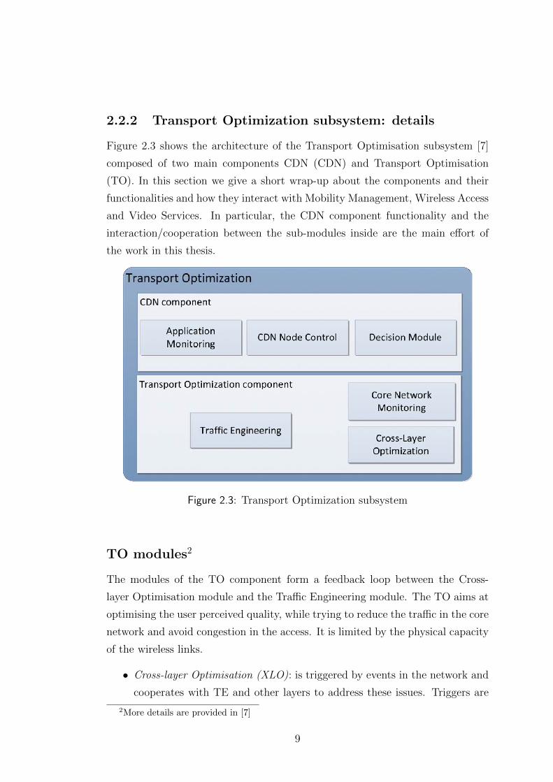

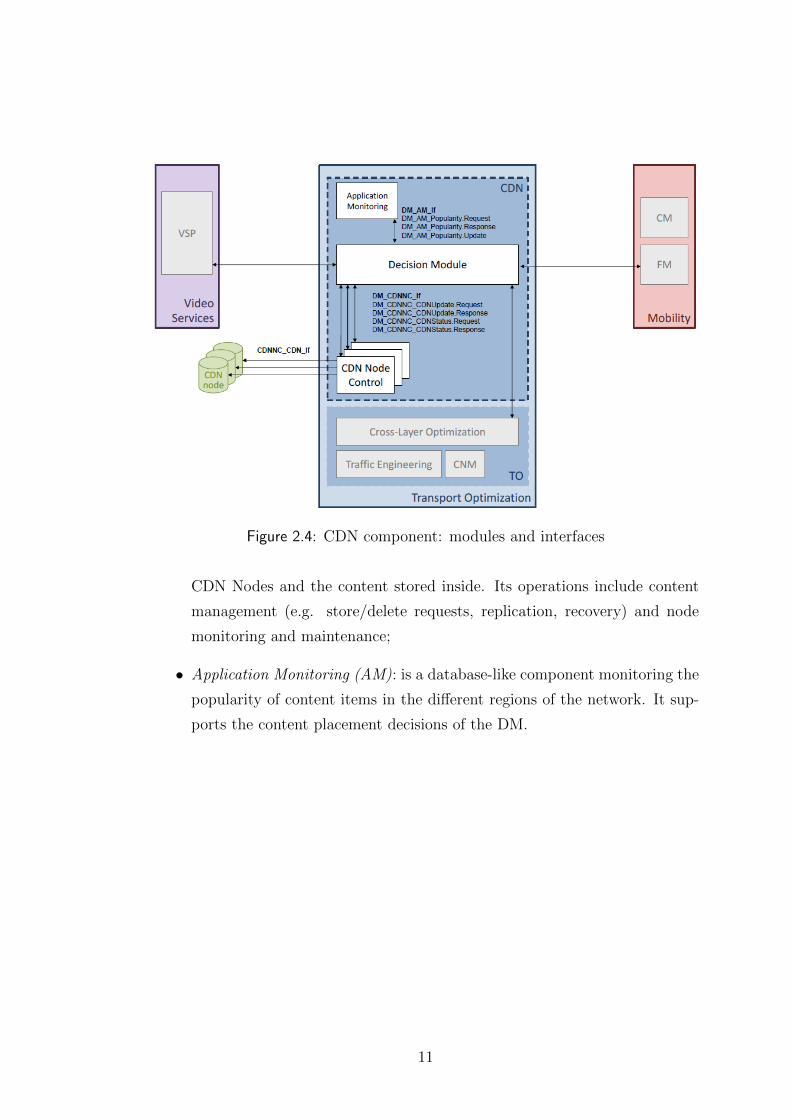


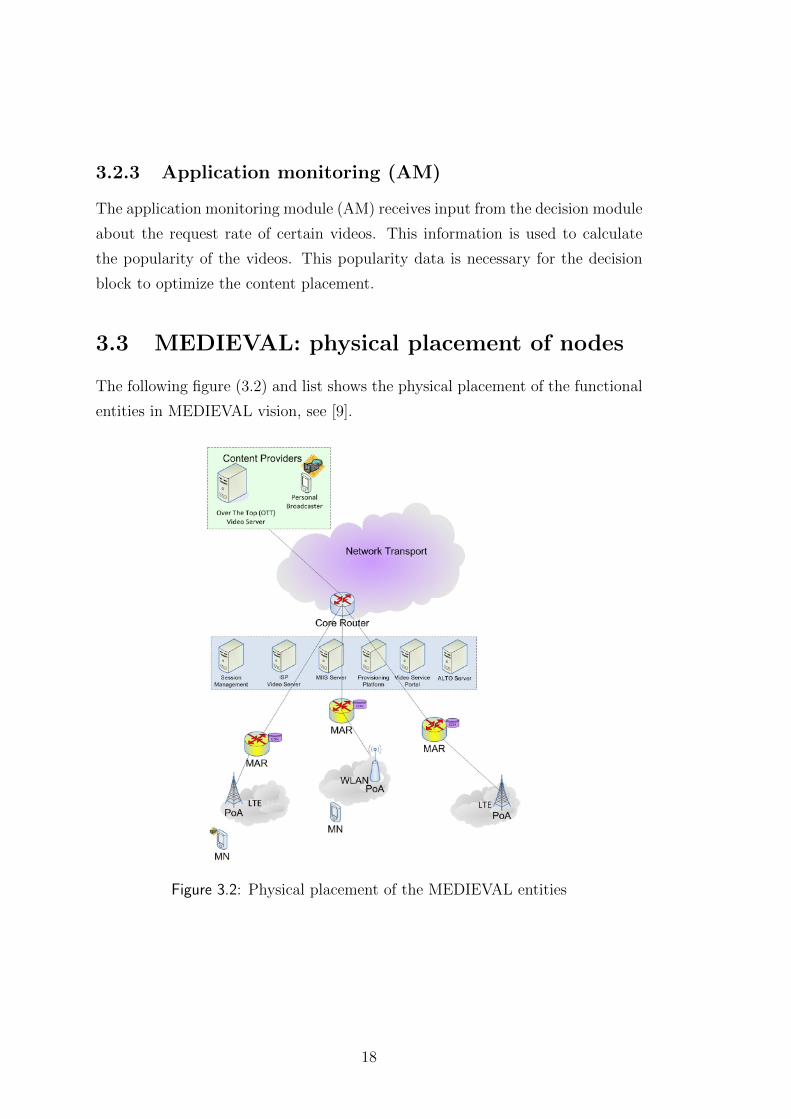


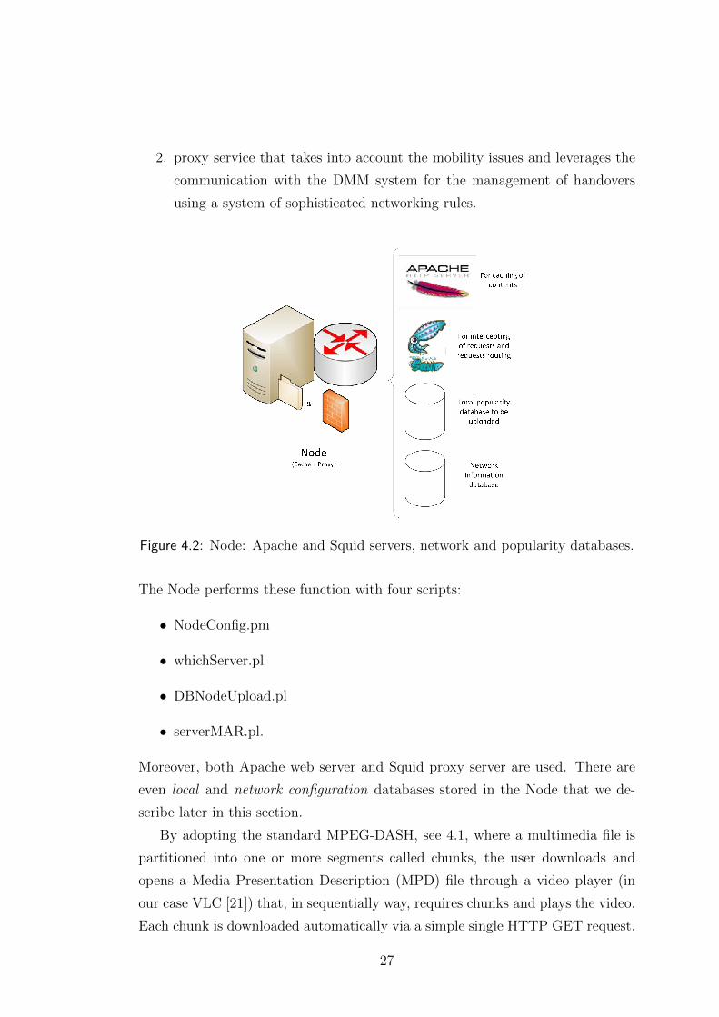


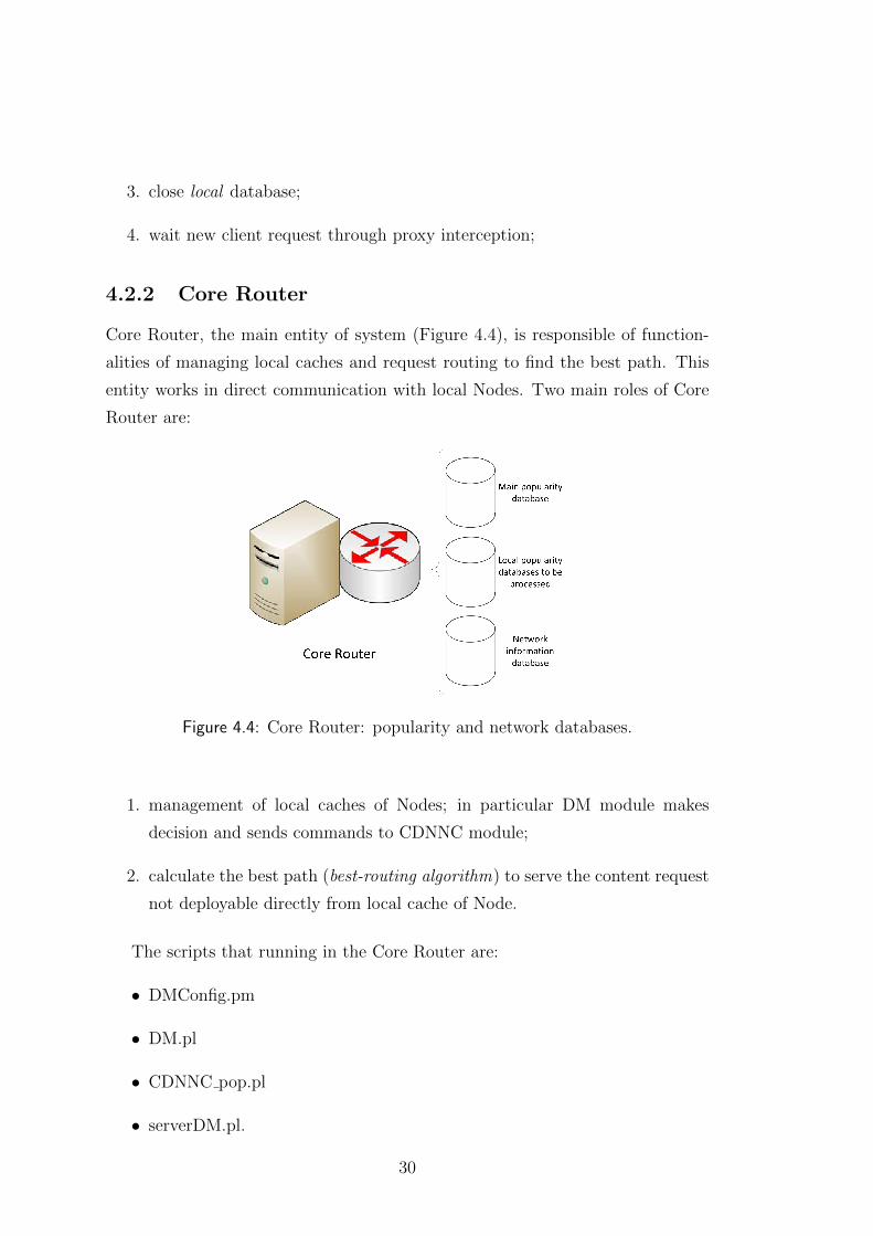
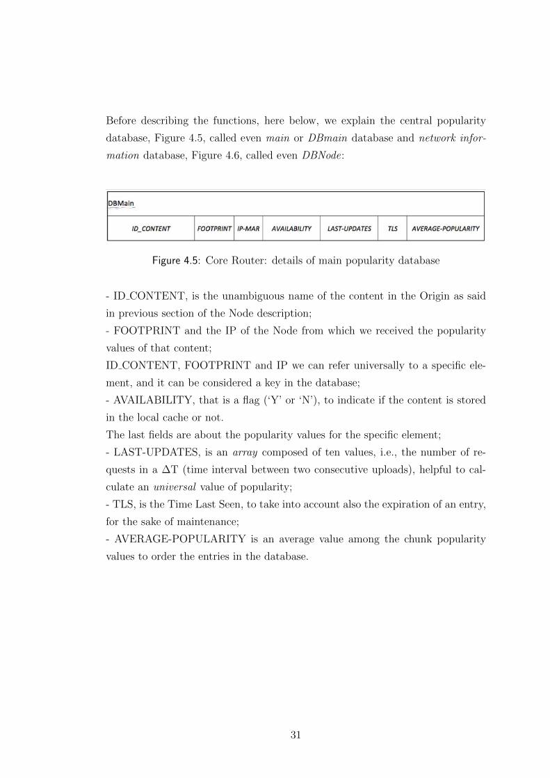
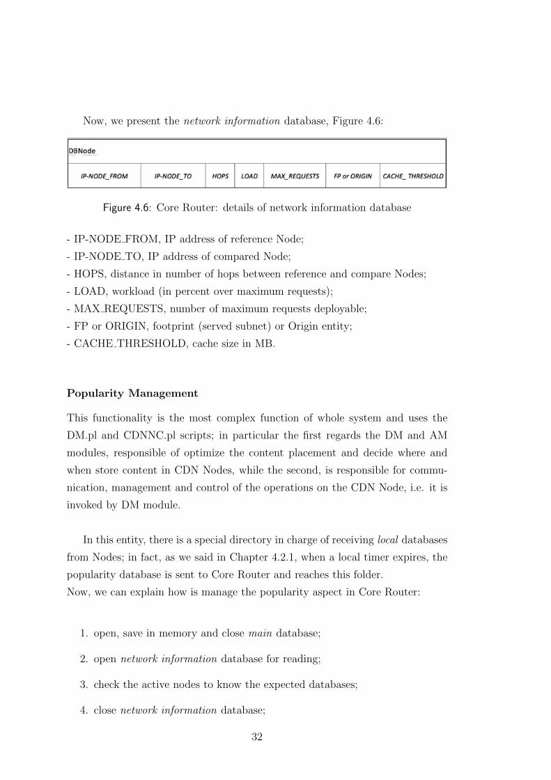


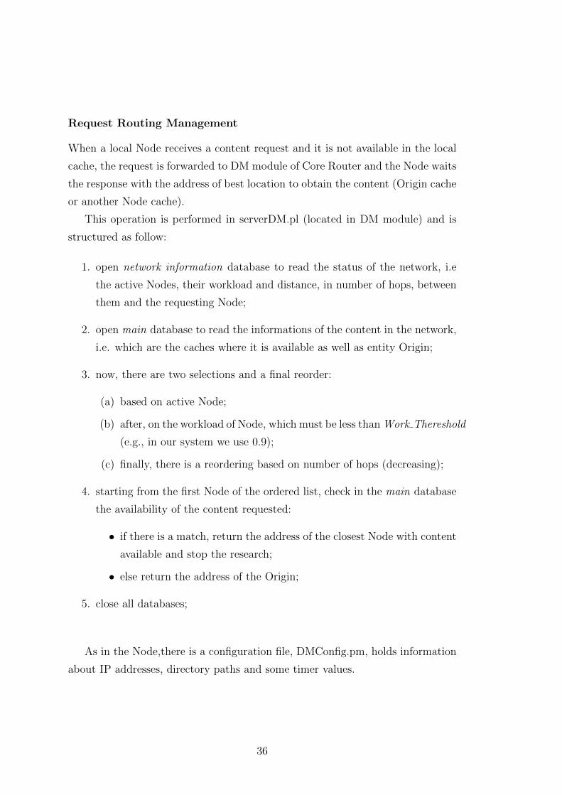
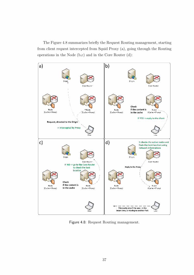
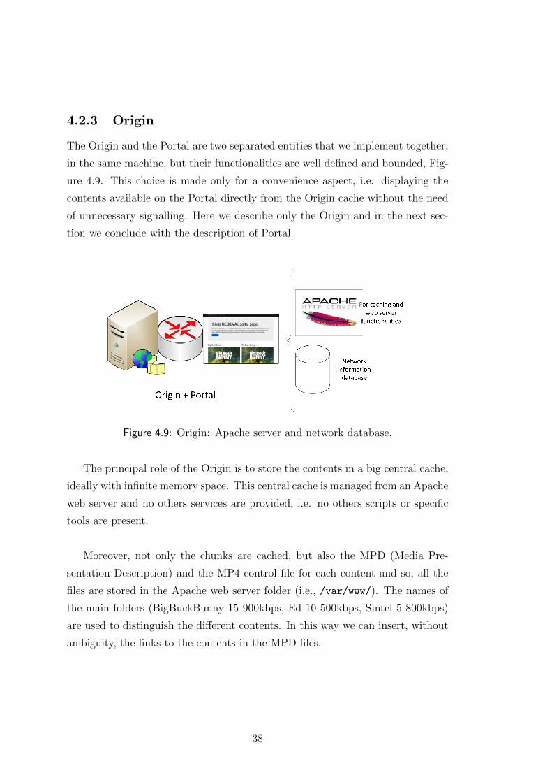


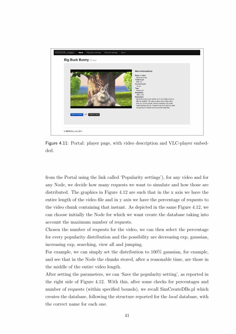


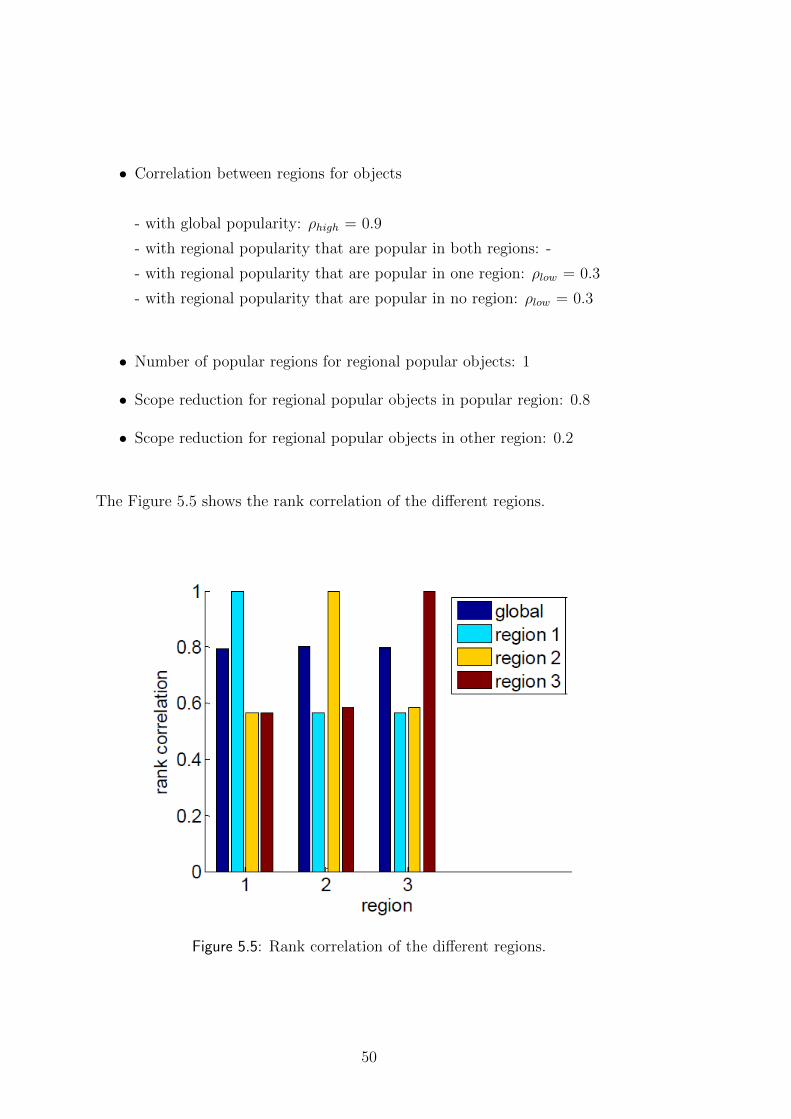


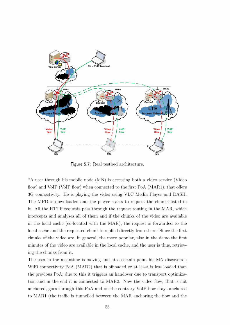


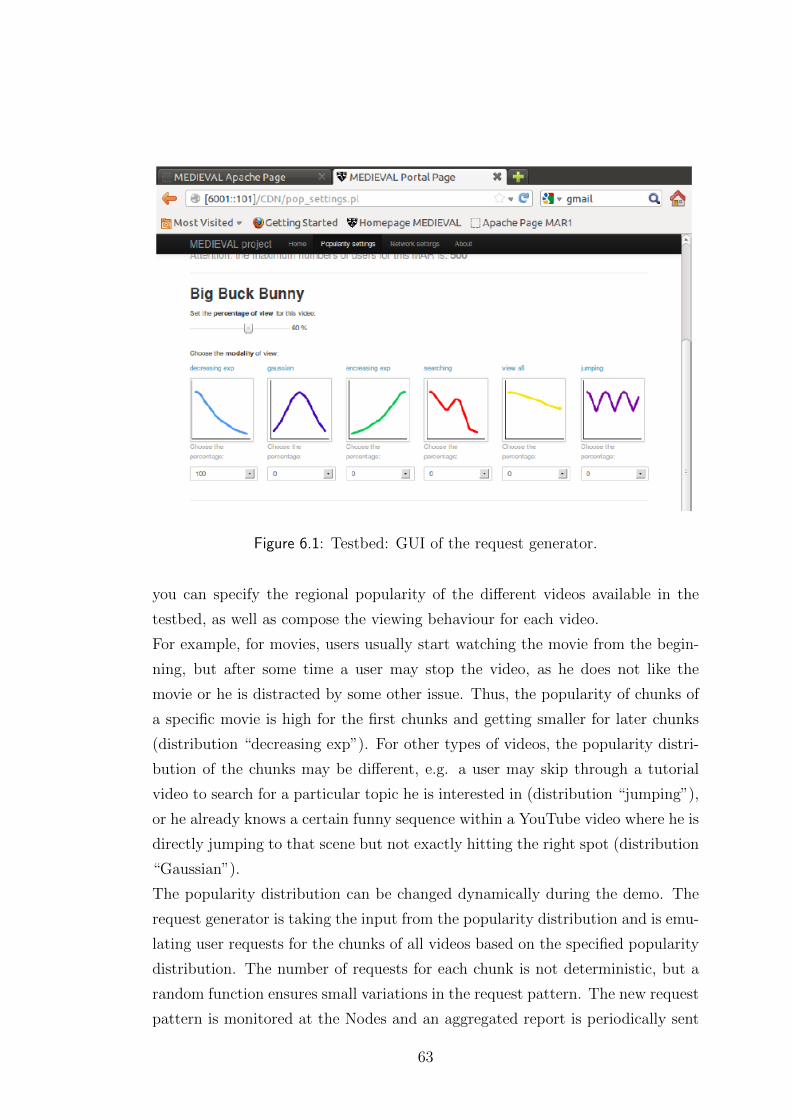


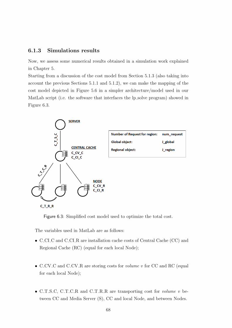


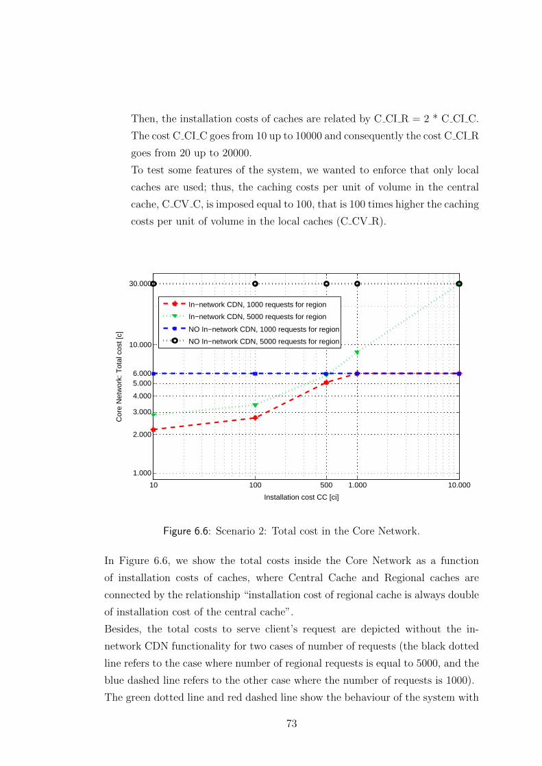


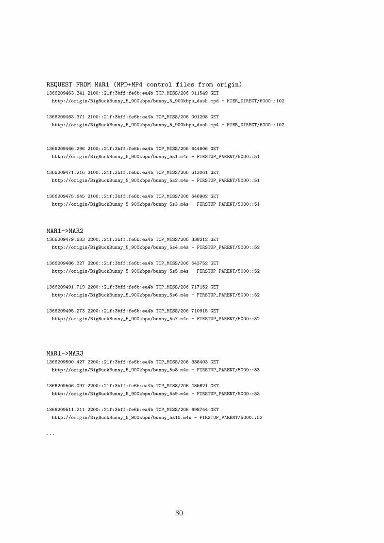


![[39]a Walk Through Content Delivery Networks](https://static.documents.pub/doc/80x56/577d1ffa1a28ab4e1e91c409/39a-walk-through-content-delivery-networks.jpg)


