28
A Practical Guide to IEC 60601 rigelmedical.com

A Practical Guide to IEC 60601
rigelmedical.com

RIGEL MEDICAL
PG 2 TESTED, TRUSTED… WORLDWIDE.
© Copyright 2019 - All rights reserved. Nothing from this edition may be multiplied, or made public in any form or manner, either electronically, mechanically, by photocopying, recording, or in any manner, without prior written consent from Seaward Electronic Ltd. This also applies to accompanying drawings and diagrams.
CONTENTS
03 Foreword
04 Introduction to IEC 60601
04 Local adaptation
05 Commonly used definitions within IEC 60601
06 Symbols and markings
07 Visual inspection
07 Ground bond (ground continuity) testing
08 Leakage measurements
10 IEC 60601-1 body model
10 Single fault condition
10 Ground leakage test
11 Enclosure leakage test
12 Patient leakage
13 Patient leakage F-Type
13 Patient auxiliary current
14 Record keeping
14 Conclusion
16 Appendix A - IEC 60601-1 test limits
17 Appendix B - IEC 60601 body model
17 Appendix C - IEC 60601 test standards (Table 1)
18 Appendix D - IEC 60601 test standards (Table 2)
24 Appendix E - Patient environment
25 Products in the Rigel Medical range
26 Accessories and services from Rigel Medical
A PRACTICAL GUIDE TO IEC 60601
PG 3
16 Appendix A - IEC 60601-1 test limits
17 Appendix B - IEC 60601 body model
17 Appendix C - IEC 60601 test standards (Table 1)
18 Appendix D - IEC 60601 test standards (Table 2)
24 Appendix E - Patient environment
25 Products in the Rigel Medical range
26 Accessories and services from Rigel Medical
Rigel Medical: We know about complying to IEC 60601-1. After reading this booklet, so will you.
At Rigel Medical, we’ve been a pioneer of biomedical test and measurement instruments for more than four decades.
Our comprehensive range of electrical safety analyzers enable biomedical and clinical engineers to confirm their adherence to a series of industry standards, manufacturers’ specifications and most importantly, keep patients, visitors, and staff safe in a healthcare environment.
Since launching the world’s first IEC 601 electrical safety analyzer in the 1970s, our user-focused developments continue to place us at the forefront of the industry. Today, our 288+ handheld electrical safety tester (testing to IEC 60101) is the first truly handheld tester of its kind to combine the features of an automatic/manual tester with asset management capability.
Alongside our commitment to quality, we also offer peace of mind to our customers who know that help and advice is always available.
Foreword This booklet is written as a guideline for people involved in testing medical electrical equipment and cannot be considered to replace the IEC 60601-1 standard.
Although all reasonable care has been taken to ensure accuracy of the information and reference figures and data have been taken from the latest versions of various standards, guidance notes and recognized ‘best practices’ to establish the recommended testing requirements, Rigel Medical, their agents and distributors, accept no responsibility for any error or omissions within this booklet, or for any misinterpretations by the user.
For clarification on any part of this booklet please contact Rigel Medical before operating any test instrument.
No part of this publication shall be deemed to form, or be part of any contract for training or equipment unless specifically referred to as an inclusion within such contract.
Rigel Medical assumes that the readers of this booklet are electronically technically competent and therefore does not accept any liability arising from accidents or fatalities resulting directly or indirectly from the tests described in this booklet.
Author: John Backes, MA
RIGEL MEDICAL
PG 4 TESTED, TRUSTED… WORLDWIDE.
Introduction to IEC 60601Not all people will understand the dangers associated with the exposure to electricity. It is this danger that has triggered several discussions relating to the safety of all members of the public.
Regulatory bodies worldwide have acknowledged the dangers of electricity by producing legislation, standards and/or guidelines to control the design of electrical appliances in order to prevent any hazard to the general public.
One environment where electric currents pose an acute threat is in the medical treatment and care of patients. Often, patients are physically connected to one or more electrical medical devices for a period of time. In these circumstances it is possible that patients are unaware of their exposure to electrical currents, especially if being treated under full or local anesthetic. During invasive treatments, the human body’s natural protection organ, the skin, no longer provides basic insulation against electrical currents. It is during these treatments that electrical currents, as low as 50mA, can travel through the human body and cause the heart to fibrillate or paralyze the respiratory system.
The International Electrotechnical Committee (IEC) has produced a standard to control all aspects of safety directly or indirectly relating to the handling, use or connection to, of medical equipment. This standard is referenced as IEC 60601.
The IEC 60601 was first published in 1977,
then referred to as IEC 601, and handles the electrical safety of both mechanical and electrical issues. It is constructed from 2 parts; IEC 60601-1 and IEC 60601-2, each built-up from a number of basic or collateral standards.
Collateral standardIEC 60601-1-x (x representing a collateral standard number between 1-12) is the collateral standard; this is the primary standard which has a number of specific standards related directly to the safety of medical equipment.
Specific standardsIEC 60601-2-x (x representing a specific standard number between 1-76), are the standards specific to various types of medical equipment, providing additional information to the collateral standards. Appendix C and D provide an overview of the IEC 60101-1- x and IEC 60601-2- x standards.
This booklet describes the electrical safety requirements for compliance with IEC 60601-1. Although a type of test standard, most of these tests are used to test medical devices, both regularly and following service or repair.
Local adaptationIn many cases the IEC 60601 standard has been adapted into local standards for use in countries around the world. Some examples are EN 60601 (EU), ANSI/AAMI ES60601 (USA), UL60601-1 (USA), CSA C22.2 no 60601-1 (Canada), JIS T 0601-1 (Japan) and AS/NZ 60601.1 (Australia/New Zealand).
Safety testing at the design stage and at the
A PRACTICAL GUIDE TO IEC 60601
PG 5
end of the production line is vitally important, but what about when the equipment enters service?
IEC 62353 Medical Electrical Equipment - Recurrent Test and Test After Repair of Medical Equipment equipment defines the requirements for electrical safety testing of medical electrical (ME) equipment and systems during routine intervals.
Following the need for a unified approach to routine testing, the first edition of IEC 62353 brought together a set number of tests to allow its users to test means of operator protection (MOOP) and means of patient protection (MOPP) dielectric integrity via two distinct leakage current tests.
In meeting this requirement the IEC 62353 incorporates tests beyond those of type testing. Specifically, it seeks to provide a uniformed and unambiguous means of assessing the safety of medical equipment, while maintaining the relevance to IEC 60601-1 and minimizing the risks to the person conducting the assessment.
Some countries have also produced standards or guidelines for the safety testing of newly-delivered medical devices, referred to as acceptance testing; testing during regular intervals, referred to as preventive maintenance tests; and testing following service or repair. Some examples are DIN VDE 0751 (Germany), AS/NZ 3551 (Australia/New Zealand), and AAMI/NFPA 99 (USA).
Countries without a national guidance or code of practice mainly follow the manufacturer’s instructions or guidelines, which most commonly refer to the IEC 60601-1 test
requirements. In essence, all standards have one thing in common: to control the safety of medical devices for use in the treatment, care and diagnosis of patients and/or individuals.
Commonly used definitions within IEC 60601Equipment under test (EUT)The equipment which is the subject of testing.
Device under test (DUT)The device which is the subject of testing.
Applied partPart of the medical equipment which is designed to, or likely to, come into physical contact with the patient e.g. EKG leads.
Patient connectionIndividual physical connections and/or metal parts intended for connection with the patient which form (part of) an applied part.
Patient environmentVolumetric area in which a patient can come into contact with medical equipment or contact can occur between other persons touching medical equipment and the patient, both intentionally and unintentionally (see Appendix E).
F-Type applied partApplied part which is electrically isolated from Ground and other parts of the medical equipment i.e. floating F-Type applied parts are either type BF or type CF applied parts.

RIGEL MEDICAL
PG 6 TESTED, TRUSTED… WORLDWIDE.
Type B applied partApplied part complying with specified requirements for protection against electric shock. Type B applied parts are those parts, which are usually Ground referenced. Type B applied parts are those parts not suitable for direct cardiac application.
Type BF applied partF-Type applied part complying with a higher degree of protection against electric shock than type B applied parts. Type BF applied parts are those parts not suitable for direct cardiac application.
Type CF applied partF-Type applied part complying with the highest degree of protection against electric shock. Type CF applied parts are those parts suitable for direct cardiac application.
Medical electrical equipmentElectrical equipment designed for treatment, monitoring or diagnoses of patients, powered from one connection to mains supply. Does not necessarily require physical or electrical contact with the patient, transfer energy to or from the patient, or detect such energy transfer to or from the patient.
Medical electrical systemA combination of equipment of which at least one is classed as medical electrical equipment and is specified by the manufacturer to be connected by functional connection or use of a multiple portable socket outlet.
Class IEquipment protection against electric shock by (Grounded) additional protection to basic
insulation through means of connecting exposed conductive parts to the protective Ground in the fixed wiring of the installation.
Class IIAlso referred to as ‘double insulated’. Equipment protection against electric shock by additional protection to basic insulation through supplementary insulation. There is no provision for the connection of exposed metalwork of the equipment to a protective conductor and no reliance upon precautions to be taken in the fixed wiring of the installation.
Note: Class II equipment may be provided with a functional Ground terminal or a functional Ground conductor.
Symbols and markingsThe IEC 60601 has defined the requirements for information/data to be present on the medical equipment’s nameplate, in order to form an unambiguous identification of the equipment.
Information must include specific manufacturer and equipment information, including manufacturer’s name, model number, serial number, and electrical requirements.
The IEC 60601 standard refers to a large variety of symbols for use on medical equipment, medical systems, accessories and other related parts. A full overview of the symbols used in IEC 60601 is provided in the standard. For the purpose of this booklet, a selection of the most

A PRACTICAL GUIDE TO IEC 60601
PG 7
commonly used symbols is displayed below:
Visual inspectionThe process of visual inspection is not clearly defined by IEC 60601, however visual inspections form a critical part of the general safety inspections during the functional life of medical equipment. Around 70% of all faults are detected during visual inspection.
Visual inspection is a relatively easy procedure to support your assessment that the medical equipment in use still conforms to the specifications as released by the manufacturer and has not suffered from any external damage and/or contamination.
These can include the following inspections:
∙ Housing enclosure – look for damage, cracks etc.
∙ Contamination – look for obstruction of moving parts, connector pins etc.
∙ Cabling (supply, applied parts etc.) – Look for cuts, wrong connections etc.
∙ Fuse rating – check correct values after replacement
∙ Markings and labeling – check the integrity of safety markings
∙ Integrity of mechanical parts – check for any obstructions
Ground bond (Ground Continuity) Testing
Ground bond testing, also referred to as Ground resistance, Ground continuity or protective Ground testing, tests the integrity of the low resistance connection between the Ground conductor and any metal conductive parts, which may become live in case of a fault on Class I medical devices.
Although many Class I medical devices are supplied with a ground reference point, most medical devices require multiple Ground bond tests to validate the connections of additional metal accessible parts on the enclosure.
The test current is applied between the Ground pin of the mains supply plug and any accessible metal part, including the Ground reference point, with a dedicated Ground bond test lead using a crocodile clip or probe.
The IEC 60601-1 (clause 8.6.4) requires a minimum test current of either 25A AC or 1.5 times the highest rated current of the relevant
Class I Class II
Groundreference point
i.e. “Conformité Européenne”
Type B applied part
Defibrillation proof type B applied part
Type BF applied part
Defibrillation proof type BF applied part
Type CF applied part
Defibrillation proof type CF applied part

RIGEL MEDICAL
PG 8 TESTED, TRUSTED… WORLDWIDE.
circuit(s), whichever is greater. The open circuit voltage of the current source should not exceed 6V.
A test current of 25A AC is most commonly used. Due to the exposure of high current, some parts of the equipment could be damaged and therefore requires a lower test current. However, the Ground bond test is designed to stress the connection under fault conditions.
Faults in the detachable power cord account for 80-90% of all Ground bond failures, as most molded power cables are prone to stress when the cables are pulled from wall outlet at an angle or otherwise stressed.
For fixed installations, such as MRI or x-ray equipment) a point-to-point continuity measurement can be made. The resistance is then measured between two probes: one connected to the incoming ground reference point and one placed on accessible, metal parts of the medical installation.
Test limits are set at 0.1Ω for fixed power cords and 0.2Ω for equipment with a detachable power cord. See Appendix A for a full overview of the IEC 60601-1 test limits.
Prolonged use of testing at high currents can lead to a high probe temperature. Care should be taken to avoid touching the probe tip under these conditions.
Leakage measurements It takes only a small amount of current to cause major consequences. Research has shown
that current, not voltage, is often the source of injury or death.
When an electrical current flows through the human body the effect is influenced by two main factors: First, the amount of current, and secondly, the length of time the current flows.
For example, the heart stops if the current persists for 250mS at 40mA, 100mS at 100mA, or 50mS at 200mA.
Consider the following examples of the effect of current on the human body when applied to the skin (non-invasive):
0.9-1.2mA Current just perceptible.
15.0-20.0mA Release impossible. Cannot be tolerated over 15 minutes.
50.0-100.0mA Ventricular fibrillation. Respiratory arrest, leading directly to death.
100.0-200.0mA Serious burns and muscular contraction of such a degree that the thoracic muscles constrict the heart.
Compare these values to the fact that 250mA of current is required to power a 25 watt lamp.
For this reason, the IEC 60601 committee has set stringent rules on the design of medical equipment to prevent any patient or operator being exposed to currents not part of the functional operation of the device. These currents are referred to as leakage currents.
IEC 60601 defines leakage current of three

A PRACTICAL GUIDE TO IEC 60601
PG 9
different sources:
Ground leakage: current flowing down the protective Ground conductor of the mains inlet lead.
Enclosure leakage: current flowing to Ground through a person by touching the medical equipment/system or part of (may be referred to as touch leakage).
Applied part or patient leakage: current flowing through a person to Ground from the applied part, or current flowing from a person to Ground through the applied part by applying unintended voltage from an external source.
Applied part/patient leakage can be classed into number of measurements such as:
∙ Patient leakage (please refer to the corresponding paragraph)
∙ Patient F-Type leakage (please refer to the corresponding paragraph)
∙ Patient auxiliary leakage (please refer to the corresponding paragraph)
Applied part or patient leakage is the most important part of leakage measurement on any medical device. Applied parts are directly in contact with the patient or, in the case of invasive devices, placed under the patient’s skin. Currents applied under the skin, which forms our natural protection against electrical currents, can result in far greater consequences, with currents as low as 15μA resulting in fatality.
The limits for leakage currents within the IEC 60601-1 requirements are set to minimizing
the probability of ventricular fibrillation to a factor as low as 0.002 – the limit of 10 μA for CF applied part under normal condition. See Appendix A for a full overview of theIEC 60601-1 test limits.
The following tests find their origin from the IEC 60601-1 but are specific to the AAMI and NFPA 99 standards (USA):
∙ Patient leakage (applied part to ground): Similar to patient leakage (see description above).
∙ Patient leakage (applied part to case): Similar to patient leakage (see description above) with leakage current path coming from the applied parts, through the patient, to the casing of the EUT/DUT.
∙ Patient Auxiliary (applied part to applied part or lead to lead): Similar to patient auxiliary current (see description above).
∙ Patient Auxiliary (applied part to all): Similar to patient auxiliary current (see description above). For the purpose of this booklet, the focus will be on the directly related leakage measurements as per IEC 60601-1.
Warning: Mains voltage applied to appliance.It is important to verify that a medical device with moving parts (such as a motor or pump) is safely mounted to allow movement, without causing damage to people or equipment. Secondary Ground paths will effect the leakage measurements and can give false PASS readings. Always make sure that the device under test is positioned safely and isolated from Ground when measuring leakage.

RIGEL MEDICAL
PG 10 TESTED, TRUSTED… WORLDWIDE.
IEC 60601-1 body model To ensure a traceable simulation of current as if passing through a human body, measurement circuits have been designed to simulate the average typical electrical characteristics of the human body. These measurement circuits are referred to as body models or measuring devices (MD in IEC 60601-1).
Some standards such as the AAMI/NFPA 99 and the IEC 61010 (Safety requirements for electrical equipment for measurement, control, and laboratory use) specify different electrical characteristics to that of the IEC 60601-1.
The IEC 60601-1 body model or measuring device is shown in Appendix B.
Single fault condition To maintain a medical device’s high level of protection during its operational life and maintain the integrity of the device’s electrical safety, a number of design features are taken into account. This is done by introducing conditions that could occur under normal use, such as reversed mains supply or voltage on signal input/output terminals (SIP/SOP), and conditions that can occur under a single fault condition (SFC).
IEC 60601-1 specifies a number of single fault conditions (SFCs) under its clause 8.1. For the purpose of this booklet, the only highlighted SFCs are the interrupted Ground connection (open Ground) and interruption of any of the supply conductors (open neutral).IEC 60601-1 specifies that all leakage measurements should be carried out using
normal and single fault conditions. A typical part of the electrical safety testing procedures is to perform the test as follows:
1. Normal supply voltage (No SFC)2. Normal supply voltage (Open neutral)3. Normal supply voltage (Open Ground)4. Reversed supply voltage (No SFC)5. Reversed supply voltage (Open neutral)6. Reversed supply voltage (Open Ground)
In addition to these tests, some manufacturers may choose to include voltage on the signal input/output terminals (i.e. communication ports such as USB or RS 232). As this test can be destructive, it is not commonly used other than during type testing of the medical electrical equipment.
Ground leakage test The Ground leakage test shows the current flowing through the medical device or its insulation into the protective Ground conductor. The Ground leakage test is important as it demonstrates the total leakage from the EUT/DUT.
IEC 60601-1 specifies that the measurements are done under normal and reverse operation and single fault condition (neutral open circuit). The Ground leakage test is valid for Class I equipment with Type B, Type BF and Type CF applied parts. Appendix A shows the pass/fail limits as per IEC 60601-1 requirements.

A PRACTICAL GUIDE TO IEC 60601
PG 11
Note: SFC ‘open Ground’ cannot be performed as this would result in zero leakage measurements under all circumstances.individual.
Diagram A shows a schematic interpretation of the Ground leakage measurement including the relays operating the single fault conditions.
Ground leakage, normal conditions This test measures the Ground leakage current under normal conditions. The current is measured through the measuring device with S1 closed, S5 normal, and then S5 reversed.
Ground leakage, single fault, supply open This test measures the Ground Leakage current with a single fault condition (supply open). The current is measured through the measuring device with S1 open, S5 normal, and then S5 reversed.
Enclosure leakage testIn general, enclosure leakage displays the current that would flow if a person came into contact with the housing (or any accessible part not intended for treatment or care) of the medical device.
IEC 60601-1 specifies that the measurements are done under normal and reverse operation of the mains supply and single fault conditions open neutral circuit and open Ground. The enclosure leakage test is valid for both Class I and II equipment with Type B, Type BF and Type CF applied parts. Appendix A shows the pass/fail limits as per IEC 60601-1 requirements.
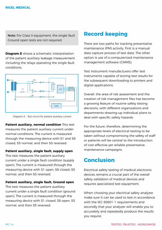
Note: For Class II equipment, the single fault Ground open tests are not required.
In the case of Class II devices, or fully insulated enclosures, this can be encapsulated by using aluminum foil of approximately 200 cm2. The enclosure leakage is measured by connecting the aluminum foil to the leakage tester.
Diagram B shows a schematic interpretation of the Ground leakage measurement including the relays operating the single fault conditions.
Enclosure leakage, normal condition This test measures the enclosure leakage current under normal conditions. The current is measured through the measuring device with S1 and S8 closed and S5 normal and reversed.
Diagram B - Test circuit for enclosure leakage
Diagram A – Test circuit for Ground leakage

RIGEL MEDICAL
PG 12 TESTED, TRUSTED… WORLDWIDE.
Enclosure leakage, single fault, supply open This test measures the enclosure leakage current with a single fault condition (Ground open). The current is measured through the measuring device with S1 open, S8 closed and S5 in normal and then S5 reversed.
Enclosure leakage, single fault, Ground open This test measures the enclosure leakage current with a single fault condition (Ground open). The current is measured through the measuring device with S1 closed, S8 open and S5 in normal and then S5 reversed.
Patient leakageThe patient leakage current is the current flowing from the applied part via the patient to Ground, or flowing from the patient via an applied part to Ground originating from an unintended voltage appearing on an external source.
IEC 60601-1 specifies that the measurements must be done under normal and reverse operation of the mains supply and single fault conditions open neutral circuit and open Ground. The patient leakage test is valid for both Class I and Class II equipment with Type B, Type BF and Type CF applied.
Appendix A shows the pass/fail limits as per IEC 60601-1 requirements.
Note: For Class II equipment, the single fault Ground open tests are not required.
For Type CF equipment the patient leakage current is measured from each applied part
separately. However, for Type B and Type BF equipment, the patient leakage current is measured with all applied parts connected together.
Diagram C shows a schematic interpretation of the patient leakage measurement, including the relays operating the single fault conditions.
Patient leakage, normal condition This test measures the patient leakage current under normal conditions. The current is measured through the measuring device with S1 and S8 closed, S5 normal, and then S5 reversed.
Patient leakage, single fault, supply open This test measures the patient leakage current with a single fault condition (Ground open). The current is measured through the measuring device with S1 closed, S8 open, S5 normal, and then S5 reversed.
Patient leakage, single fault, Ground open This test measures the patient leakage current with a single fault condition (Ground open). The current is measured through the measuring device with S1 closed, S8 open, S5 normal, and then S5 reversed.
Diagram C - Test circuit for patient leakage current

A PRACTICAL GUIDE TO IEC 60601
PG 13
Diagram D - Test circuit for patient leakage current mains on applied part
Patient leakage: F-TypeThe patient leakage F-Type Test (also known as mains on applied part test) displays the current that would flow if a mains potential was applied to the applied part which was attached to a patient (i.e. a single fault condition). This test is applied only to Type BF and Type CF equipment.
This test involves applying a current limited mains potential (110% of mains input voltage) to the applied part connections. Due to the requirements for IEC 60601-1, this test current can be in excess of 5mA under short circuit conditions, and is therefore hazardous to the user. Caution should be taken when conducting this test. Current limiting is achieved with a limiting resistor in series with the measurement circuit.
IEC 60601-1 specifies that leakage current for Type CF applied parts is measured from each of the patient connection/applied parts separately. For Type BF equipment, the leakage current is measured with all parts of the same type of applied part connected together, shown in Diagram D.
The F-Type leakage test is valid for both Class I and Class II equipment. It is measured under mains normal or reverse and source voltage normal or reverse conditions. Appendix A shows the pass/fail limits as per IEC 60601-1 requirements.
Diagram D shows a schematic interpretation of the F-Type leakage measurement including the relays operating the single fault conditions.
The current is measured through the measuring device with S1 and S8 closed. S5 and S9 are switched between normal and reversed.
Patient auxiliary current
The patient auxiliary current displays the leakage current that would flow between applied parts under normal and fault conditions. For these tests, current is measured between a single part of the applied part and all other applied parts connected together. This test should be repeated until all combinations have been tested. This is also referred to as applied part to all.
IEC 60601-1 specifies that the measurements be carried out under normal and reverse operation of the mains supply and single fault conditions open neutral circuit and open Ground. The patient auxiliary leakage test is valid for both Class I and II equipment with Type B, Type BF, and Type CF applied.
RIGEL MEDICAL
PG 14 TESTED, TRUSTED… WORLDWIDE.
Note: For Class II equipment, the single fault Ground open tests are not required.
Diagram E shows a schematic interpretation of the patient auxiliary leakage measurement including the relays operating the single fault conditions.
Patient auxiliary, normal condition This test measures the patient auxiliary current under normal conditions. The current is measured through the measuring device with S1 and S8 closed, S5 normal, and then S5 reversed.
Patient auxiliary, single fault, supply open This test measures the patient auxiliary current under a single fault condition (supply open). The current is measured through the measuring device with S1 open, S8 closed, S5 normal, and then S5 reversed.
Patient auxiliary, single fault, Ground open This test measures the patient auxiliary current under a single fault condition (ground open). The current is measured through the measuring device with S1 closed, S8 open, S5 normal, and then S5 reversed.
Record keepingThere are two paths for tracking preventative maintenance (PM) activity. First is a manual data capture process of test data. The other option is use of a computerized maintenance management software (CMMS).
Test instrument manufacturers offer test instruments capable of storing test results for the subsequent downloading to printers and digital applications.
Overall, the area of risk assessment and the creation of risk management files has become a growing feature of routine safety testing decisions, with different organizations and departments drawing-up individual plans to deal with specific safety hazards.
For the future, therefore, determining the appropriate levels of electrical testing to be taken without compromising the safety of staff or patients will be central to the introduction of cost effective yet reliable preventative maintenance campaigns.
ConclusionElectrical safety testing of medical electronic devices remains a crucial part of the overall safety validation of medical devices and requires specialized test equipment.
When choosing your electrical safety analyzer, make sure it can be used to test in accordance with the IEC 60601-1 requirements and secondly that your analyzer will enable you to accurately and repeatedly produce the results you require.
Diagram E - Test circuit for patient auxiliary current

A PRACTICAL GUIDE TO IEC 60601
PG 15
Essential requirements for electrical safety analyzers are:
∙ User safety – this must never be compromised
∙ The measuring device meets the frequency response of the IEC 60601-1 body model
∙ High accuracy and repeatability of leakage measurement readings. Some manufacturers may specify accuracy of full scale reading which will affect the accuracy of low leakage measurements
∙ Traceability of measurement results. Do you require data storage?
∙ Test convenience, including test duration, user interface, time efficiency
Rigel Medical offers a range of test equipment in line with the IEC 60601 requirements.
Please visit our website www.rigelmedical.com for a full overview of our product offering or register online for our free newsletter on future product releases and product innovations.
For further questions or comments relating to this booklet or on the Rigel Medical product offering, please contact our Rigel team via email at [email protected]
RIGEL MEDICAL
PG 16 TESTED, TRUSTED… WORLDWIDE.
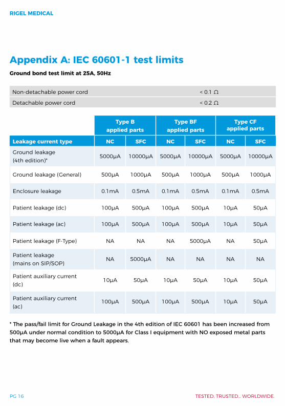
Appendix A: IEC 60601-1 test limits Ground bond test limit at 25A, 50Hz
Non-detachable power cord < 0.1 Ω
Detachable power cord < 0.2 Ω
Type Bapplied parts
Type BFapplied parts
Type CFapplied parts
Leakage current type NC SFC NC SFC NC SFC
Ground leakage (4th edition)*
5000μA 10000μA 5000μA 10000μA 5000μA 10000μA
Ground leakage (General) 500µA 1000µA 500µA 1000µA 500µA 1000µA
Enclosure leakage 0.1mA 0.5mA 0.1mA 0.5mA 0.1mA 0.5mA
Patient leakage (dc) 100μA 500μA 100μA 500μA 10μA 50μA
Patient leakage (ac) 100μA 500μA 100μA 500μA 10μA 50μA
Patient leakage (F-Type) NA NA NA 5000μA NA 50μA
Patient leakage (mains on SIP/SOP)
NA 5000μA NA NA NA NA
Patient auxiliary current (dc)
10μA 50μA 10μA 50μA 10μA 50μA
Patient auxiliary current (ac)
100μA 500μA 100μA 500μA 10μA 50μA
* The pass/fail limit for Ground Leakage in the 4th edition of IEC 60601 has been increased from 500μA under normal condition to 5000μA for Class I equipment with NO exposed metal parts that may become live when a fault appears.

A PRACTICAL GUIDE TO IEC 60601
PG 17
Appendix B: IEC 60601 body model
Appendix C: IEC 60601 test standardsTable 1 – IEC 60601 Collateral Standards(© IEC Geneva, Switzerland)
IEC 60601-1 Medical electrical equipment - Part 1: General requirements for basic safety and essential performance
IEC 60601-1-2 Medical electrical equipment - Part 1-2: General requirements for basic safety and essential performance - Collateral Standard: Electromagnetic disturbances - Requirements and tests
Diagram F - Example of a measuring device according to IEC 60601-1 and its frequency characteristics
z (f)
z (f
= 10
)
Note: The network and voltage measuring instrument above are replaced by the symbol in the following figures:
a) Non-inductive componentsb) Impedance >> measuring impedance Zc) Z (f) is the transfer impedance of the network, i.e. V out/in, for a current frequency f
RIGEL MEDICAL
PG 18 TESTED, TRUSTED… WORLDWIDE.
IEC 60601-1-3 Medical electrical equipment - Part 1-3: General requirements for basic safety and essential performance - Collateral Standard: Radiation protection in diagnostic X-ray equipment
IEC 60601-1-6 Medical electrical equipment - Part 1-6: General requirements for basic safety and essential performance - Collateral standard: Usability
IEC 60601-1-8 Medical electrical equipment - Part 1-8: General requirements for basic safety and essential performance - Collateral Standard: General requirements, tests and guidance for alarm systems in medical electrical equipment and medical electrical systems
IEC 60601-1-9Medical electrical equipment - Part 1-9: General requirements for basic safety and essential performance - Collateral Standard: Requirements for environmentally conscious design
IEC 60601-1-10Medical electrical equipment - Part 1-10: General requirements for basic safety and essential performance - Collateral Standard: Requirements for the development of physiologic closed-loop controllers
IEC 60601-1-11Medical electrical equipment – Part 1-11: General requirements for basic safety and essential performance – Collateral Standard: Requirements for medical electrical equipment and medical electrical systems used in the home healthcare environment
IEC 60601-1-12Medical electrical equipment - Part 1-12: General requirements for basic safety and essential performance - Collateral Standard: Requirements for medical electrical equipment and medical electrical systems intended for use in the emergency medical services environment
Appendix D: IEC 60601 test standardsTable 2 – IEC 60601 Specific Standards(© IEC Geneva, Switzerland)
IEC 60601-2-1 Medical electrical equipment - Part 2-1: Particular requirements for the basic safety and essential performance of electron accelerators in the range 1 MeV to 50 MeV

A PRACTICAL GUIDE TO IEC 60601
PG 19
IEC 60601-2-2Medical electrical equipment - Part 2-2: Particular requirements for the basic safety and essential performance of high frequency surgical equipment and high frequency surgical accessories
IEC 60601-2-3Medical electrical equipment - Part 2-3: Particular requirements for the basic safety and essential performance of short-wave therapy equipment
IEC 60601-2-4 Medical electrical equipment - Part 2-4: Particular requirements for the basic safety and essential performance of cardiac defibrillators
IEC 60601-2-5Medical electrical equipment - Part 2-5: Particular requirements for the basic safety and essential performance of ultrasonic physiotherapy equipment
IEC 60601-2-6Medical electrical equipment - Part 2-6: Particular requirements for the basic safety and essential performance of microwave therapy equipment
IEC 60601-2-8 Medical electrical equipment - Part 2-8: Particular requirements for the basic safety and essential performance of therapeutic X-ray equipment operating in the range 10kV to 1MV
IEC 60601-2-10 Medical electrical equipment - Part 2-10: Particular requirements for the basic safety and essential performance of nerve and muscle stimulators
IEC 60601-2-11Medical electrical equipment - Part 2-11: Particular requirements for the basic safety and essential performance of gamma beam therapy equipment
IEC 60601-2-16Medical electrical equipment - Part 2-16: Particular requirements for basic safety and essential performance of haemodialysis, haemodiafiltration and haemofiltration equipment
IEC 60601-2-17 Medical electrical equipment - Part 2-17: Particular requirements for the basic safety and essential performance of automatically-controlled brachytherapy after loading equipment

RIGEL MEDICAL
PG 20 TESTED, TRUSTED… WORLDWIDE.
IEC 60601-2-18Medical electrical equipment - Part 2-18: Particular requirements for the basic safety and essential performance of endoscopic equipment
IEC 60601-2-19 Medical electrical equipment - Part 2-19: Particular requirements for the basic safety and essential performance of infant incubators
IEC 60601-2-20Medical electrical equipment - Part 2-20: Particular requirements for the basic safety and essential performance of infant transport incubators
IEC 60601-2-21 Medical electrical equipment - Part 2-21: Particular requirements for the basic safety and essential performance of infant radiant warmers
IEC 60601-2-22Medical electrical equipment - Part 2-22: Particular requirements for basic safety and essential performance of surgical, cosmetic, therapeutic and diagnostic laser equipment
IEC 60601-2-23Medical electrical equipment - Part 2-23: Particular requirements for the basic safety and essential performance of transcutaneous partial pressure monitoring equipment
IEC 60601-2-24Medical electrical equipment - Part 2-24: Particular requirements for the basic safety and essential performance of infusion pumps and controllers
IEC 60601-2-25Medical electrical equipment - Part 2-25: Particular requirements for the basic safety and essential performance of electrocardiographs
IEC 60601-2-26Medical electrical equipment - Part 2-26: Particular requirements for the basic safety and essential performance of electroencephalographs
IEC 60601-2-27Medical electrical equipment - Part 2-27: Particular requirements for the basic safety and essential performance of electrocardiographic monitoring equipment
A PRACTICAL GUIDE TO IEC 60601
PG 21
IEC 60601-2-28Medical electrical equipment - Part 2-28: Particular requirements for the basic safety and essential performance of X-ray tube assemblies for medical diagnosis
IEC 60601-2-29Medical electrical equipment - Part 2-29: Particular requirements for the basic safety and essential performance of radiotherapy simulators
IEC 60601-2-31Medical electrical equipment - Part 2-31: Particular requirements for the basic safety and essential performance of external cardiac pacemakers with internal power source
IEC 60601-2-33 Medical electrical equipment - Part 2-33: Particular requirements for the basic safety and essential performance of magnetic resonance equipment for medical diagnosis
IEC 60601-2-34Medical electrical equipment - Part 2-34: Particular requirements for the basic safety and essential performance of invasive blood pressure monitoring equipment
IEC 60601-2-36Medical electrical equipment - Part 2-36: Particular requirements for the basic safety and essential performance of equipment for extra corporeally induced lithotripsy
IEC 60601-2-37Medical electrical equipment - Part 2-37: Particular requirements for the basic safety and essential performance of ultrasonic medical diagnostic and monitoring equipment
IEC 60601-2-39 Medical electrical equipment - Part 2-39: Particular requirements for basic safety and essential performance of peritoneal dialysis equipment
IEC 60601-2-40Medical electrical equipment - Part 2-40: Particular requirements for the basic safety and essential performance of electromyographs and evoked response equipment
IEC 60601-2-41Medical electrical equipment - Part 2-41: Particular requirements for the basic safety and essential performance of surgical luminaires and luminaires for diagnosis

RIGEL MEDICAL
PG 22 TESTED, TRUSTED… WORLDWIDE.
IEC 60601-2-43Medical electrical equipment - Part 2-43: Particular requirements for the basic safety and essential performance of X-ray equipment for interventional procedures
IEC 60601-2-44 Medical electrical equipment - Part 2-44: Particular requirements for the basic safety and essential performance of X-ray equipment for computed tomography
IEC 60601-2-45Medical electrical equipment - Part 2-45: Particular requirements for basic safety and essential performance of mammographic X-ray equipment and mammomagraphic stereotactic devices
IEC 60601-2-46 Medical electrical equipment - Part 2-46: Particular requirements for the basic safety and essential performance of operating tables
IEC 60601-2-47Medical electrical equipment - Part 2-47: Particular requirements for the basic safety and essential performance of ambulatory electrocardiographic systems
IEC 60601-2-50Medical electrical equipment - Part 2-50: Particular requirements for the basic safety and essential performance of infant phototherapy equipment
IEC 60601-2-52 Medical electrical equipment - Part 2-52: Particular requirements for the basic safety and essential performance of medical beds
IEC 60601-2-54Medical electrical equipment - Part 2-54: Particular requirements for the basic safety and essential performance of X-ray equipment for radiography and radioscopy
IEC 60601-2-57 Medical electrical equipment - Part 2-57: Particular requirements for the basic safety and essential performance of non-laser light source equipment intended for therapeutic, diagnostic, monitoring and cosmetic/aesthetic use
IEC 60601-2-62Medical electrical equipment - Part 2-62: Particular requirements for the basic safety and essential performance of high intensity therapeutic ultrasound (HITU) equipment

A PRACTICAL GUIDE TO IEC 60601
PG 23
IEC 60601-2-63Medical electrical equipment - Part 2-63: Particular requirements for the basic safety and essential performance of dental extra-oral X-ray equipment
IEC 60601-2-64Medical electrical equipment - Part 2-64: Particular requirements for the basic safety and essential performance of light ion beam medical electrical equipment
IEC 60601-2-65 Medical electrical equipment - Part 2-65: Particular requirements for the basic safety and essential performance of dental intra-oral X-ray equipment
IEC 60601-2-66Medical electrical equipment - Part 2-66: Particular requirements for the basic safety and essential performance of hearing instruments and hearing instrument systems
IEC 60601-2-68Electrical medical equipment - Part 2-68: Particular requirements for the basic safety and essential performance of X-ray-based image-guided radiotherapy equipment for use with electron accelerators, light ion beam therapy equipment and radionuclide beam therapy equipment
IEC 60601-2-75Medical electrical equipment - Part 2-75: Particular requirements for the basic safety and essential performance of photodynamic therapy and photodynamic diagnosis equipment
IEC 60601-2-76Medical electrical equipment - Part 2-76: Particular requirements for the basic safety and essential performance of low energy ionized gas haemostasis equipment

RIGEL MEDICAL
PG 24 TESTED, TRUSTED… WORLDWIDE.
Diagram G – Patient environment
Appendix E: Patient environment

A PRACTICAL GUIDE TO IEC 60601
PG 25
288+Accurate and fast electrical safety tester
∙ Light, handheld, battery operation* ∙ Conforms to IEC 62353 / 60601 / VDE 0751
/ NFPA-99 / AS-NZS 3551 ∙ Memory for up to 5,000 devices ∙ Bluetooth communication ∙ Full, semi-automatic and manual testing ∙ Straightforward data transfer with the Rigel
288+ Downloader app
Products in the Rigel Medical range
SafeTest 50A cost-effective medical safety analyzer for general electrical safety testing
∙ Light, handheld, universal AC inputvoltage
∙ Complies with NFPA-99 ∙ Large color display ∙ Secondary ground warning ∙ Manual control of SFC, minimal power
cycling
Download our free Rigel Medical product brochure to see the full range: www.rigelmedical.com/rigel-downloads

RIGEL MEDICAL
PG 26 TESTED, TRUSTED… WORLDWIDE.
Accessories and services from Rigel Medical
AccessoriesHaving the right accessories can streamline your testing processes and help you get the most from your instrument. Our range of accessories includes scanners, Bluetooth enabled printers, a variety of leads and adaptors, pass/fail labels and verification units.
To see the full range of Rigel Medical accessories available, visit www.rigelmedical.com/accessories
TrainingAlongside our commitment to quality, we also offer peace of mind to our customers who know that help and advice is always available. Part of that offering includes training to support and help you get the most from your instrument.
Contact us directly to find out more.
Online resources & supportAt Rigel Medical we take pride in giving you all of the tools to make your life easier. We have a host of online resources and technical support features on our website including, FAQs, interactive videos and helpful how-to guides.
www.rigelmedical.com/support
Service, calibration & repairRigel Medical can also take care of your test and measurement equipment by providing calibration services (including on-site calibration), service, spares and repairs. Extend the life and quality of your instruments by contacting us for a no-obligation quote, wherever you are in the world.
www.rigelmedical.com/service-centre

A PRACTICAL GUIDE TO IEC 60601
PG 27
Notes

www.rigelmedical.com Rev 1.1
Seaward Group USA, 6304 Benjamin Road, Suite 506, Tampa, FL 33634
T: +1 813-886-2775 E: [email protected]
Rigel Medical Rigel Medical Rigel Medical Rigel Medical


