19 A Principle and Characteristics of a Flexible and Stretchable Tactile Sensor Based on Static Electricity Yasunori Tada 1 , Masahiro Inoue 2 , Toshimi Kawasaki 3 , Yasushi Kawahito 3 , Hiroshi Ishiguro 2 and Katsuaki Suganuma 2 1 Nagoya Institute of Technology, 2 Osaka University, 3 Togawa Rubber Co., Ltd. Japan 1. Introduction Tactile sensors are required for various robots such as robot hands and humanoid robots. In some humanoid robots, the tactile sensor is utilized for interacting with the human. For example, when many humans interact with the humanoid robot such as Robovie, they often try to stroke the robot's head, to hug the robot, or to shake hands (Tajika et al., 2006). To recognize such communications, some humanoid robots have the tactile sensor over the robot's whole body. Existing tactile sensors for humanoid robots were proposed in the following studies. Tajima et al. (Tajima et al., 2002) proposed a distributed tactile sensor made of conductive fabric and gel. Ohmura et al. (Ohmura et al., 2006) proposed a tactile sensor that the sensor elements were mounted on the flexible printed circuit board. Robovie utilizes the robot skin that piezoelectric films were embedded in the silicone rubber (Miyashita et al., 2007). These tactile sensors have flexibility. The flexibility is important feature. If the surface of the humanoid robots is flexible, the uncomfortable feeling when the human hugs the humanoid robot will be reduced. Moreover, the flexibility is expected to improve the safeness. Moreover, the stretch ability of the tactile sensor has advantages that the sensor is not frangible and that the sensor can be easily mounted on curved surfaces or deformable parts such as joints. However, many existing tactile sensors (Shan et al., 2005; Mizuuchi et al., 2006; Koterba & Matsuoka, 2006) have the flexibility, but do not have the stretch ability. Hoshi and Shinoda (Hoshi & Shinoda, 2006) proposed flexible and stretchable robot skin made of conductive fabric and urethane foam. However, they did not discuss the sensor output when the skin is stretched. This paper proposes a flexible and stretchable tactile sensor which is expected to be suited for humanoid robots. The sensor can detect touch and release by using the static electricity and the electrostatic induction. The static electricity and the electrostatic induction are well- known phenomena from old times. However, we do not know a sensor that these phenomena were utilized as the tactile sensor. However, there is a sensor to distinguish Open Access Database www.intechweb.org Source: Sensors, Focus on Tactile, Force and Stress Sensors, Book edited by: Jose Gerardo Rocha and Senentxu Lanceros-Mendez, ISBN 978-953-7619-31-2, pp. 444, December 2008, I-Tech, Vienna, Austria www.intechopen.com
Transcript
19
A Principle and Characteristics of a Flexible and Stretchable Tactile Sensor
1Nagoya Institute of Technology, 2Osaka University,
3Togawa Rubber Co., Ltd. Japan
1. Introduction
Tactile sensors are required for various robots such as robot hands and humanoid robots. In some humanoid robots, the tactile sensor is utilized for interacting with the human. For example, when many humans interact with the humanoid robot such as Robovie, they often try to stroke the robot's head, to hug the robot, or to shake hands (Tajika et al., 2006). To recognize such communications, some humanoid robots have the tactile sensor over the robot's whole body. Existing tactile sensors for humanoid robots were proposed in the following studies. Tajima
et al. (Tajima et al., 2002) proposed a distributed tactile sensor made of conductive fabric and
gel. Ohmura et al. (Ohmura et al., 2006) proposed a tactile sensor that the sensor elements
were mounted on the flexible printed circuit board. Robovie utilizes the robot skin that
piezoelectric films were embedded in the silicone rubber (Miyashita et al., 2007). These
tactile sensors have flexibility. The flexibility is important feature. If the surface of the
humanoid robots is flexible, the uncomfortable feeling when the human hugs the humanoid
robot will be reduced. Moreover, the flexibility is expected to improve the safeness.
Moreover, the stretch ability of the tactile sensor has advantages that the sensor is not
frangible and that the sensor can be easily mounted on curved surfaces or deformable parts
such as joints. However, many existing tactile sensors (Shan et al., 2005; Mizuuchi et al.,
2006; Koterba & Matsuoka, 2006) have the flexibility, but do not have the stretch ability.
Hoshi and Shinoda (Hoshi & Shinoda, 2006) proposed flexible and stretchable robot skin
made of conductive fabric and urethane foam. However, they did not discuss the sensor
output when the skin is stretched.
This paper proposes a flexible and stretchable tactile sensor which is expected to be suited for humanoid robots. The sensor can detect touch and release by using the static electricity and the electrostatic induction. The static electricity and the electrostatic induction are well-known phenomena from old times. However, we do not know a sensor that these phenomena were utilized as the tactile sensor. However, there is a sensor to distinguish O
pen
Acc
ess
Dat
abas
e w
ww
.inte
chw
eb.o
rg
Source: Sensors, Focus on Tactile, Force and Stress Sensors, Book edited by: Jose Gerardo Rocha and Senentxu Lanceros-Mendez, ISBN 978-953-7619-31-2, pp. 444, December 2008, I-Tech, Vienna, Austria
www.intechopen.com
Sensors, Focus on Tactile, Force and Stress Sensors
342
materials which utilized the static electricity (Shida et al., 2007). By using the static electricity, the sensor consists of only the charged bodies and the conductive material, and has very simple structure. In this paper, the sensor is made of the soft silicone rubber because the sensor is expected flexible and stretchable. The characteristics of the sensor are investigated by some experiments. The remainder of this paper is organized as follows. First, a principle of the sensor is introduced. The sensor utilizes the static electricity and the electrostatic induction phenomenon. In a next session, some experiments are shown to demonstrate characteristics of the sensor. A first experiment shows sensor responses when several objects touch the sensor. A second experiment shows the sensor output when the sensor is stretched. A final experiment shows the influence of a cross-talk noise. In a final session, we conclude this paper.
2. Principle of the sensor
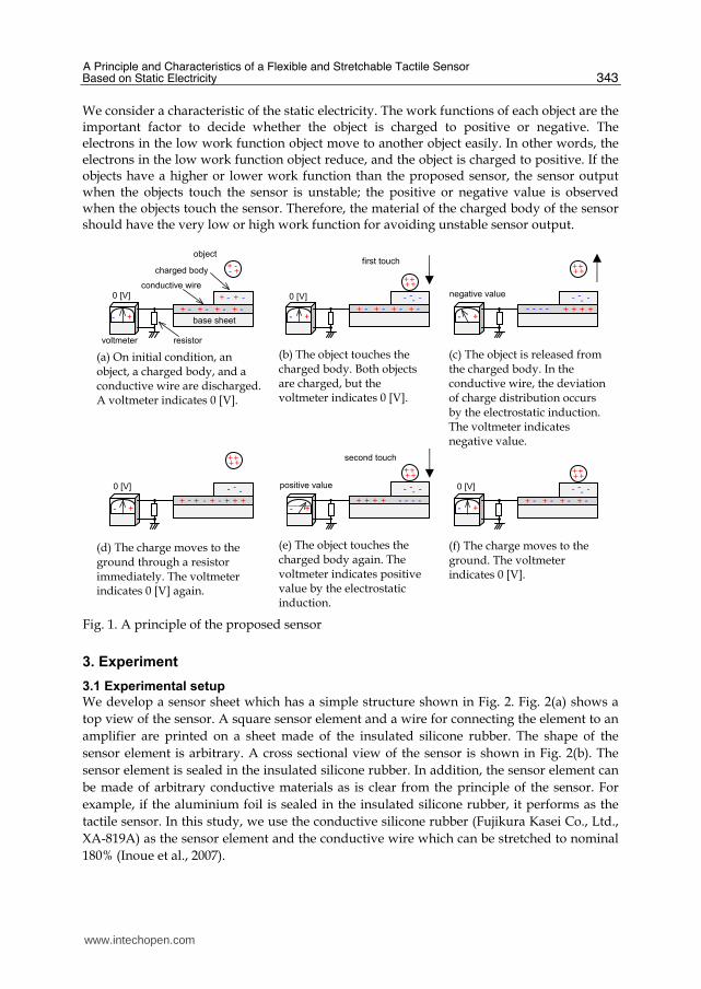
A principle of the proposed tactile sensor is shown in Fig. 1. Fig. 1(a) shows a structure of a sensor system. The sensor consists of a base sheet at the bottom of the sensor, a conductive wire on the base sheet, and a charged body on the conductive wire. The conductive wire is connected to the ground through a resistor. A voltmeter measures voltage between the wire and the ground. The structure of the sensor is similar to capacitive tactile sensors. However, the principle of the proposed sensor is different from the existing tactile sensors. The existing capacitive tactile sensors measure the transition of the capacitance whereas the proposed sensor measures the static electricity. In the proposed sensor, when an object touches the charged body of the sensor, the static electricity occurs in the object and the sensor. Moreover, at this time, the static electricity generates the electrostatic induction in the wire. Therefore, the charged body and the conductive wire are performed as the tactile sensor by measuring the voltage of the electrostatic induction. Each step of the principle is described in the following. The sensor and an object are
discharged on initial condition shown in Fig. 1(a). A first step is shown in Fig. 1(b). The
static electricity occurs in the sensor and the object when the object touches the sensor.
However, the electrostatic induction does not occur in this step, and the voltmeter continues
to indicate 0 [V] because the quantities of the positive and negative electric charges are the
same. In the figure, the object and the sensor are charged to the positive and the negative,
respectively. Fig. 1(c) shows a second step. When the object is released from the sensor, the
electrostatic induction occurs in the wire because of effect of the negative charge in the
charged body. In other words, the positive charges are collected under the charged body,
and the negative charges are collected at near the resistor. Therefore, the voltmeter indicates
negative value. A third step is shown in Fig. 1(d). The charges move to the ground because
the wire is connected to the ground through the resistor, and the voltmeter indicates 0 [V]. A
fourth step is shown in Fig. 1(e). When the positive charged object approximates to the
sensor, the electrostatic induction occurs in the wire again. At this step, the positive charges
are collected at near the resistor, and the voltmeter indicates the positive value.
Additionally, the reason that both the charged body and the wire are charged to the
negative is the difference of the quantity of charge between the object and the sensor. Fig.
1(f) shows a final step. The charges move to the ground, and the voltmeter indicates 0 [V].
Therefore, the proposed sensor can detect touch and release by the principle.
www.intechopen.com
A Principle and Characteristics of a Flexible and Stretchable Tactile Sensor Based on Static Electricity
343
We consider a characteristic of the static electricity. The work functions of each object are the important factor to decide whether the object is charged to positive or negative. The electrons in the low work function object move to another object easily. In other words, the electrons in the low work function object reduce, and the object is charged to positive. If the objects have a higher or lower work function than the proposed sensor, the sensor output when the objects touch the sensor is unstable; the positive or negative value is observed when the objects touch the sensor. Therefore, the material of the charged body of the sensor should have the very low or high work function for avoiding unstable sensor output.
3. Experiment
3.1 Experimental setup
We develop a sensor sheet which has a simple structure shown in Fig. 2. Fig. 2(a) shows a
top view of the sensor. A square sensor element and a wire for connecting the element to an
amplifier are printed on a sheet made of the insulated silicone rubber. The shape of the
sensor element is arbitrary. A cross sectional view of the sensor is shown in Fig. 2(b). The
sensor element is sealed in the insulated silicone rubber. In addition, the sensor element can
be made of arbitrary conductive materials as is clear from the principle of the sensor. For
example, if the aluminium foil is sealed in the insulated silicone rubber, it performs as the
tactile sensor. In this study, we use the conductive silicone rubber (Fujikura Kasei Co., Ltd.,
XA-819A) as the sensor element and the conductive wire which can be stretched to nominal
180% (Inoue et al., 2007).
+ - - +
+ - + - + - + -
+ - + -
base sheet
voltmeter resistor
conductive wire
charged body
object
++
+ - + - + - + -
- -0 [V]
++
- -
+ +
+ - + - + - + - - -
+ +
- -
++
+ - + + - +-
-0 [V]
++
- - ++
++
+ -+ -+ -+ -
- -
- +
++
--
+ +
+ - + - + - + -
- - 0 [V]
+ +
- -
(a) On initial condition, an object, a charged body, and a conductive wire are discharged. A voltmeter indicates 0 [V].
(b) The object touches the charged body. Both objects are charged, but the voltmeter indicates 0 [V].
(c) The object is released from the charged body. In the conductive wire, the deviation of charge distribution occurs by the electrostatic induction. The voltmeter indicates negative value.
(d) The charge moves to the ground through a resistor immediately. The voltmeter indicates 0 [V] again.
(e) The object touches the charged body again. The voltmeter indicates positive value by the electrostatic induction.
(f) The charge moves to the ground. The voltmeter indicates 0 [V].
second touch
first touch
negative value
positive value
0 [V]
- + - +- +
- + - +
Fig. 1. A principle of the proposed sensor
www.intechopen.com
Sensors, Focus on Tactile, Force and Stress Sensors
344
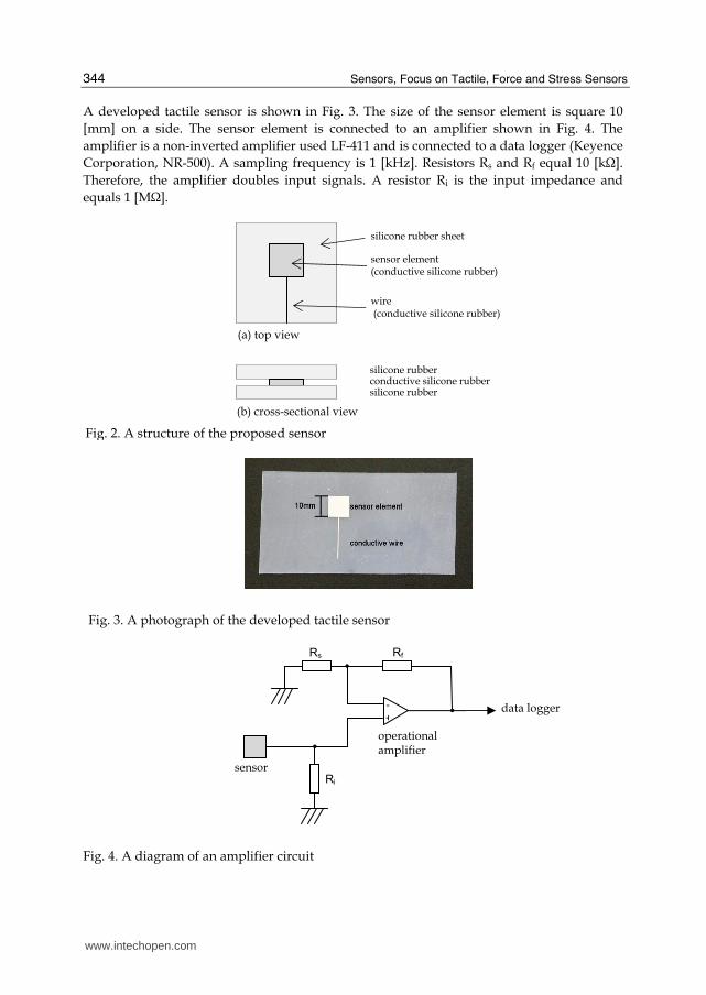
A developed tactile sensor is shown in Fig. 3. The size of the sensor element is square 10
[mm] on a side. The sensor element is connected to an amplifier shown in Fig. 4. The
amplifier is a non-inverted amplifier used LF-411 and is connected to a data logger (Keyence
Corporation, NR-500). A sampling frequency is 1 [kHz]. Resistors Rs and Rf equal 10 [kΩ].
Therefore, the amplifier doubles input signals. A resistor Ri is the input impedance and
equals 1 [MΩ].
Fig. 3. A photograph of the developed tactile sensor
data logger
sensor
-
+
Ri
Rf Rs
operational amplifier
Fig. 4. A diagram of an amplifier circuit
silicone rubber sheet
sensor element (conductive silicone rubber)
wire (conductive silicone rubber)
(b) cross-sectional view
(a) top view
silicone rubber
silicone rubberconductive silicone rubber
Fig. 2. A structure of the proposed sensor
www.intechopen.com
A Principle and Characteristics of a Flexible and Stretchable Tactile Sensor Based on Static Electricity
345
3.2 Characteristics
Fig. 5 shows an example of the sensor output when a human finger touches the sensor. From this figure, the positive value is observed when the finger touches the sensor. The sensor output returns to 0 [V] shortly after the touch. In contrast, the negative value is observed when the finger leaves the sensor. This output characteristic is observed at some objects which are made of different materials. Additionally, the characteristic will change as is pointed out in the section 2 if the sensor is made of different materials. The silicone rubber used in this study is charged to negative very strongly. Therefore, the sensor output shows positive value when almost all the objects touch the sensor.
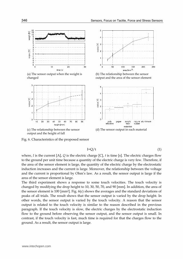
We investigate the output characteristics of the developed sensor by four experiments: 1) a response to some weights, 2) a response to some areas of the sensor element, 3) a response to some touch velocities, and 4) a response to some materials of the touching object. In 1) to 3) experiments, we use an object N for touching the sensor. It is a cylinder made of acrylic resin (diameter = 20 [mm], height = 40 [mm]), and a natural rubber sheet is pasted on the bottom surface. In addition, the experiments 2) to 4) are iterated 50 times for each experimental condition. The first experiment shows a response to some weights. The object N is put on the sensor element on initial condition, and the weight is changed by a compression testing machine. Time courses of the weight and the sensor output are shown in Fig. 6(a). The weight varies 0 [N] to 12 [N]. However, the sensor output continues to indicate 0 [V] because the static electricity does not occur if the contact condition is not changed. Therefore, the sensor does not respond to the weight. In addition, the vibration is observed in the time course of the weight. The reason is that the noise from a motor in the compression testing machine affects a load transducer. The second experiment shows a response to some areas of the sensor element. The areas of the sensor element are 25, 50, 100, 150, and 225 [mm2]. The object N is dropped from 30 [mm] height and the sensor output is observed. Because of the bounce of the object, the sensor output is vibratory signal. Thus, we consider a first peak of the sensor output in each trial as a trial result. Fig. 6(b) shows the averages and the standard deviations of peaks of all trials. The figure shows that amplitude of the sensor output is varied by the area of the sensor element. A reason that the sensor output is related to the area of the sensor element is as follows. The current is found by equation (1).
Fig. 5. An example of the sensor output when the human touches the sensor
www.intechopen.com
Sensors, Focus on Tactile, Force and Stress Sensors
346
I=Q/t (1)
where, I is the current [A], Q is the electric charge [C], t is time [s]. The electric charges flow
to the ground per unit time because a quantity of the electric charge is very few. Therefore, if
the area of the sensor element is large, the quantity of the electric charge by the electrostatic
induction increases and the current is large. Moreover, the relationship between the voltage
and the current is proportional by Ohm’s law. As a result, the sensor output is large if the
area of the sensor element is large.
The third experiment shows a response to some touch velocities. The touch velocity is
changed by modifying the drop height to 10, 30, 50, 70, and 90 [mm]. In addition, the area of
the sensor element is 100 [mm2]. Fig. 6(c) shows the averages and the standard deviations of
peaks of all trials. The result shows that the sensor output is varied by the drop height. In
other words, the sensor output is varied by the touch velocity. A reason that the sensor
output is related to the touch velocity is similar to the reason described in the previous
paragraph. If the touch velocity is slow, the electric charges by the electrostatic induction
flow to the ground before observing the sensor output, and the sensor output is small. In
contrast, if the touch velocity is fast, much time is required for that the charges flow to the
ground. As a result, the sensor output is large.
(a) The sensor output when the weight is changed
(c) The relationship between the sensor output and the height of fall
(b) The relationship between the sensor output and the area of the sensor element
(d) The sensor output in each material
Fig. 6. Characteristics of the proposed sensor
www.intechopen.com
A Principle and Characteristics of a Flexible and Stretchable Tactile Sensor Based on Static Electricity
347
The fourth experiment shows a response to some materials of the touching object. In this experiment, the area of the sensor element and the drop height is 100 [mm2] and 30 [mm], respectively. The dropped objects are an aluminium cylinder (diameter = 20 [mm], height = 30[mm]), an acrylic resin cylinder (diameter = 20 [mm], height = 40 [mm]), a polyethylene sheet, a copier paper, and a natural rubber sheet. To make easy the experiment, the polyethylene sheet, the copier paper, and the natural rubber sheet are pasted on the bottom surface of the acrylic resin cylinder (diameter = 20 [mm], height = 40 [mm]). Fig. 6(d) shows the averages and the standard deviations of peaks of all trials. The figure shows that the sensor output is varied by the material of the touching object. It is caused by that the quantity of the static electricity is different by the material of the object.
3.3 Stretchable tactile sensor
In this study, the stretchable conductive silicone rubber is utilized as the tactile sensor element. The silicone rubber keeps electrical conductivity when the rubber is stretched to triple length. Therefore, even if the element is stretched by the external force, the sensor is expected to perform as the tactile sensor. The sensor output when the sensor is stretched is investigated by experiments. We show two experiments in this section. A first experiment shows sensor output when the sensor element is stretching. Another experiment shows sensor output when an object touches the stretched sensor element. The first experiment shows sensor output when a sensor element is stretching to one way. A shape of the sensor element is square, and its size is 10 [mm] on a side. A tension tester is utilized for stretching the sensor element. Elongation speed is 1000 [mm/min] and elongation length is 40 [mm]. However, the actual elongation length of the sensor element is 10 [mm] because of allowance of fixing jig and deformation characteristics of the silicone rubber. Fig. 7 shows an experimental result. The tension tester is operating from 1 to 3.4 [s]. However, the sensor output is not varied. A reason is that the static electricity does not occur only if the sensor element is stretched. In addition, the sensor output is vibratory as compared to other results because of noise from the tension tester.
The second experiment shows sensor output when an object touches the stretched sensor element. Fig. 8 shows a tactile sensor used in the experiment. An upper photograph shows an unstretched tactile sensor that the size is 5×5 [mm]. The sensor shown in a lower
Fig. 7. The sensor output when the sensor is stretching.
www.intechopen.com
Sensors, Focus on Tactile, Force and Stress Sensors
348
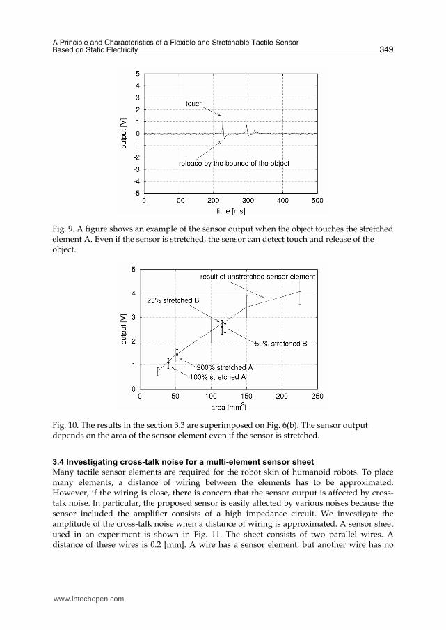
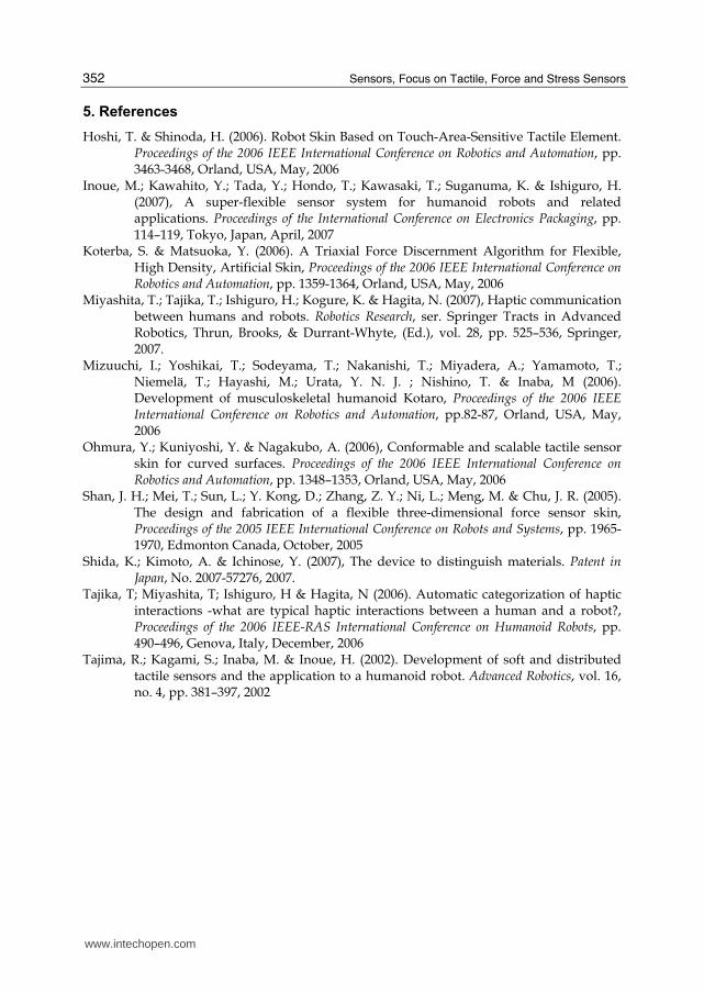
photograph is the same sensor but is stretched to triple length. As a result, the size of the sensor element is changed to 15×3.5 [mm]. In the experiment, two sensors are tested as the stretchable sensor. The size of a tactile sensor element A is 5×5 [mm]. The elongation percentages of the element A are 100% and 200%. The size of another sensor element B is 10×10 [mm]. The elongation percentages of the element B are 25% and 50%. At before and after the stretch, the sizes and the areas of the sensor elements are shown in Table 1. The sensor output when the object N used in the previous section is dropped from 30 [mm] height is observed. Fig. 9 shows an example of the sensor output when the object touches the stretched element A. The figure shows that the sensor performs as the tactile sensor even if the sensor is stretched. The experiment is iterated 50 times for each elongation percentage. The averages and the standard deviations of peaks of all trials are calculated and compared with Fig. 6(b). A result is shown in Fig. 10. The figure shows that the sensor output depends on the area of the sensor element even if the sensor is stretched.
unstretched 100% stretched 200% stretched
element A 5×5 [mm] 25 [mm2]
10×4 [mm] 40 [mm2]
15×3.5 [mm] 52.5 [mm2]
unstretched 25% stretched 50% stretched
element B 10×10 [mm]
100[mm2] 12.5×9.25 [mm]
117.75 [mm2] 15×8 [mm] 120 [mm2]
Table 1. The sizes and areas of the sensor elements
(a) 5×5 [mm]sensor elemnt
(b) The same sensor elemnt is stretched to triple lentgh.
Fig. 8. Photographs show the same sensor element. The element shown in an upper photograph is unstretched. A lower photograph shows the same sensor element which is stretched to triple length to the lateral direction.
www.intechopen.com
A Principle and Characteristics of a Flexible and Stretchable Tactile Sensor Based on Static Electricity
349
3.4 Investigating cross-talk noise for a multi-element sensor sheet
Many tactile sensor elements are required for the robot skin of humanoid robots. To place many elements, a distance of wiring between the elements has to be approximated. However, if the wiring is close, there is concern that the sensor output is affected by cross-talk noise. In particular, the proposed sensor is easily affected by various noises because the sensor included the amplifier consists of a high impedance circuit. We investigate the amplitude of the cross-talk noise when a distance of wiring is approximated. A sensor sheet used in an experiment is shown in Fig. 11. The sheet consists of two parallel wires. A distance of these wires is 0.2 [mm]. A wire has a sensor element, but another wire has no
Fig. 9. A figure shows an example of the sensor output when the object touches the stretched element A. Even if the sensor is stretched, the sensor can detect touch and release of the object.
Fig. 10. The results in the section 3.3 are superimposed on Fig. 6(b). The sensor output depends on the area of the sensor element even if the sensor is stretched.
www.intechopen.com
Sensors, Focus on Tactile, Force and Stress Sensors
350
sensor element. The area of the sensor element is 100 [mm2]. The sensor output when a finger touches the sensor element is shown in Fig. 12. In Fig. 12(a), a red and a green line show the output of the sensor element and the wiring, respectively. Fig. 12(b) shows a magnified view of Fig. 12(a). In the figure, blue broken lines show a standard deviation of the output of the wiring. The figure shows that the output of the wiring is not affected by the cross-talk noise. From this result, we developed a sensor sheet which has six sensor elements shown in Fig. 13. In the figure, a square which has vertical lines is a sensor element. A flexible connector is placed on the sheet. The shortest distance between each wire is 0.2 [mm] at the flexible connector. However, the sensor output is not affected by the cross-talk noise.
Fig. 12. Figures show the sensor output when the finger touches the sensor element. The output of the sensor element is very large whereas the output of the wiring is very small. From this figure, the proposed sensor is not affected by cross-talk noise.
(a) A figure shows that the sensor output of the element and the wiring.
(b) A y-axis of the left figure is magnified. Moreover, a standard deviation of the wiring output is shown by blue broken lines.
output of the sensor element
output of the wiring
standard deviation of the output of the wiring
Fig. 11. A figure shows a sensor sheet to investigate the cross-talk noise. The sheet consists of two conductive wires. A wire has a sensor element, but another wire has no sensor element.
0.2mm
10mm
amplifier 1 amplifier 2
wiring only
sensor element
10mm
www.intechopen.com
A Principle and Characteristics of a Flexible and Stretchable Tactile Sensor Based on Static Electricity
351
4. Conclusion
This paper proposed the novel tactile sensor utilized the static electricity and the
electrostatic induction phenomenon. The sensor consisted of the charged body and the
conductive sensor element only. Additionally, the structure of the sensor was very simple.
The arbitrary materials were utilized as the sensor. In this paper, the sensor element and the
charged body were made of the conductive and the insulated silicone rubber, respectively.
Therefore, the developed sensor was flexible and stretchable. Some experiments were
performed to investigate the characteristics of the sensor. The first experimental results
showed that the sensor output depends on the area of the sensor element, the velocity of the
touch, and the material of the object. However, the sensor did not response to the weight. In
the second experiments, the sensor output when the sensor was stretched was investigated.
The result showed that even if the sensor had been stretched, the sensor could detect touch
and release. Additionally, the stretched sensor output also depended on the area of the
sensor element. The final experiment showed the proposed sensor is not affected by the
cross-talk noise.
The proposed sensor is not to respond to the weight as described above. In general, the
characteristic is seemed as a disadvantage. However, it is expected as an advantage if a
designer wants to detect just touch and release. Additionally, the sensor is expected to
distinguish materials of the objects because the sensor output is varied by the material. We
expect that the sensor has advantages in some applications.
On the other hand, there are some disadvantages. To detect the touch of the object, the
object has to be charged. Therefore, the proposed sensor should not apply to the collision
detection which requires the reliability. Additionally, if the sensor has a dusty or humidity
surface, the static electricity does not occur. As a result, the sensing ability is reduced.
In the future work, we investigate the other characteristics of the sensor: rubbing, rolling,
and vibration. Moreover, to avoid the depending on the condition of the sensor surface, the
other structure of the sensor is proposed.
Fig. 13. A photograph shows a developed multi-element sensor sheet. The sensor consists of the six sensor elements and a flexible connector. A square which has vertical lines is a sensor element.
www.intechopen.com
Sensors, Focus on Tactile, Force and Stress Sensors
352
5. References
Hoshi, T. & Shinoda, H. (2006). Robot Skin Based on Touch-Area-Sensitive Tactile Element. Proceedings of the 2006 IEEE International Conference on Robotics and Automation, pp. 3463-3468, Orland, USA, May, 2006
Inoue, M.; Kawahito, Y.; Tada, Y.; Hondo, T.; Kawasaki, T.; Suganuma, K. & Ishiguro, H. (2007), A super-flexible sensor system for humanoid robots and related applications. Proceedings of the International Conference on Electronics Packaging, pp. 114–119, Tokyo, Japan, April, 2007
Koterba, S. & Matsuoka, Y. (2006). A Triaxial Force Discernment Algorithm for Flexible, High Density, Artificial Skin, Proceedings of the 2006 IEEE International Conference on Robotics and Automation, pp. 1359-1364, Orland, USA, May, 2006
Miyashita, T.; Tajika, T.; Ishiguro, H.; Kogure, K. & Hagita, N. (2007), Haptic communication between humans and robots. Robotics Research, ser. Springer Tracts in Advanced Robotics, Thrun, Brooks, & Durrant-Whyte, (Ed.), vol. 28, pp. 525–536, Springer, 2007.
Mizuuchi, I.; Yoshikai, T.; Sodeyama, T.; Nakanishi, T.; Miyadera, A.; Yamamoto, T.; Niemelä, T.; Hayashi, M.; Urata, Y. N. J. ; Nishino, T. & Inaba, M (2006). Development of musculoskeletal humanoid Kotaro, Proceedings of the 2006 IEEE International Conference on Robotics and Automation, pp.82-87, Orland, USA, May, 2006
Ohmura, Y.; Kuniyoshi, Y. & Nagakubo, A. (2006), Conformable and scalable tactile sensor skin for curved surfaces. Proceedings of the 2006 IEEE International Conference on Robotics and Automation, pp. 1348–1353, Orland, USA, May, 2006
Shan, J. H.; Mei, T.; Sun, L.; Y. Kong, D.; Zhang, Z. Y.; Ni, L.; Meng, M. & Chu, J. R. (2005). The design and fabrication of a flexible three-dimensional force sensor skin, Proceedings of the 2005 IEEE International Conference on Robots and Systems, pp. 1965-1970, Edmonton Canada, October, 2005
Shida, K.; Kimoto, A. & Ichinose, Y. (2007), The device to distinguish materials. Patent in Japan, No. 2007-57276, 2007.
Tajika, T; Miyashita, T; Ishiguro, H & Hagita, N (2006). Automatic categorization of haptic interactions -what are typical haptic interactions between a human and a robot?, Proceedings of the 2006 IEEE-RAS International Conference on Humanoid Robots, pp. 490–496, Genova, Italy, December, 2006
Tajima, R.; Kagami, S.; Inaba, M. & Inoue, H. (2002). Development of soft and distributed tactile sensors and the application to a humanoid robot. Advanced Robotics, vol. 16, no. 4, pp. 381–397, 2002
www.intechopen.com
Sensors: Focus on Tactile Force and Stress SensorsEdited by Jose Gerardo Rocha and Senentxu Lanceros-Mendez
ISBN 978-953-7619-31-2Hard cover, 444 pagesPublisher InTechPublished online 01, December, 2008Published in print edition December, 2008
InTech ChinaUnit 405, Office Block, Hotel Equatorial Shanghai No.65, Yan An Road (West), Shanghai, 200040, China
Phone: +86-21-62489820 Fax: +86-21-62489821
This book describes some devices that are commonly identified as tactile or force sensors. This is achievedwith different degrees of detail, in a unique and actual resource, through the description of differentapproaches to this type of sensors. Understanding the design and the working principles of the sensorsdescribed here requires a multidisciplinary background of electrical engineering, mechanical engineering,physics, biology, etc. An attempt has been made to place side by side the most pertinent information in orderto reach a more productive reading not only for professionals dedicated to the design of tactile sensors, butalso for all other sensor users, as for example, in the field of robotics. The latest technologies presented in thisbook are more focused on information readout and processing: as new materials, micro and sub-microsensors are available, wireless transmission and processing of the sensorial information, as well as someinnovative methodologies for obtaining and interpreting tactile information are also strongly evolving.
How to referenceIn order to correctly reference this scholarly work, feel free to copy and paste the following:
Yasunori Tada, Masahiro Inoue, Toshimi Kawasaki, Yasushi Kawahito, Hiroshi Ishiguro and KatsuakiSuganuma (2008). A Principle and Characteristics of a Flexible and Stretchable Tactile Sensor Based on StaticElectricity, Sensors: Focus on Tactile Force and Stress Sensors, Jose Gerardo Rocha and SenentxuLanceros-Mendez (Ed.), ISBN: 978-953-7619-31-2, InTech, Available from:http://www.intechopen.com/books/sensors-focus-on-tactile-force-and-stress-sensors/a_principle_and_characteristics_of_a_flexible_and_stretchable_tactile_sensor_based_on_static_electri