Copyright is owned by the Author of the thesis. Permission is given for a copy to be downloaded by an individual for the purpose of research and private study only. The thesis may not be reproduced elsewhere without the permission of the Author.
Transcript
Copyright is owned by the Author of the thesis. Permission is given for a copy to be downloaded by an individual for the purpose of research and private study only. The thesis may not be reproduced elsewhere without the permission of the Author.
A QUALITY CONTROL SYSTEM FOR 'l'HE MANUFAC'l'URE OF'
SPRAY DRIED MILK POWDERS
A the s i s presente d in part ial
fulfilmen t of the requirements for
the degree o f Doctor of Philosophy
in Techno logy at Mas s ey Un iversity
CHRISTOPHER GROSVENOR BLOORE
Februar y , 1 98 1
':'68�1-Jiit
'l'o my wife , Jane
i i
ABSTRACT
In th e last decade the New Zea land dairy industry has g reatly
inc re a s ed its spray dryin g capac ity in r esponse to the wor l d mark et
demand for spray dr i e d m i l k products . Powder specifications a r e becoming
i nc r ea s ingly complex and sma l l e r quantities of each product are requ i r e d
a s t h e numbe r o f dif ferent products grows . These factors have made it
necessary to l earn more about the way proce s s ing var iabl e s inf luence the
p roduct qual ity in order to improve product qua lity contr o l .
A compute r s imul ation mode l prov iding a complete des c r ipt ion o f
t h e drier beh a v iour was developed f rom a s eries of exper iments o n a
pilot scale spray dr i e r . Th is took the form of regress ion e quations
r e lat ing the qua l ity parameter s of s k im m ilk powder to the drier
operating var iabl es and the composition and phys ical properties of the
s k im mi lk . The mode l was then used in the development of a qual ity
c ontrol s ystem and a l s o to simulate and eval uate a variety of comme r c i a l
operating practices .
Th e characte r istic s of th e spray drying process were investigated
u s ing the pi lot plant e vaporator and spray drier at the New Zea l and
D a i ry Res earch Institute , which h a d been f u l l y instr umente d and
i nterf aced to a process control computer . The dr ier studies con f ir med
the importance o f low conc entrate v is cos ity in the production o f good
qual ity m ilk powder . Th is co uld be achie ved by keepin g conce ntrate
h o lding times to a minimum and by using h i gh temperature , short t ime
preheat treatments . Th e prote in content o f the s k im m i l k was f o und to
b e the ma j or determinant in the seasona l changes observed in concentrate
v iscos ity , h i gh p rotein contents givin g h i gh vis cos ities .
The study o f the hydrodynamics o f centrifugal pres sure nozzle
a tomisers revea l e d that the nozz les used in mil k powder drying fall into
two distinct cate gories , each with characteristic behaviour in r e s pons e
t o var iations i n f luid viscosit y . Th e magnitude o f the viscos ity e f f ect
d epends on the ratio of the swirl chamber and or i f ice diamete r s . The
l ar ge capac ity noz z les used
d ecrease in pres s ure drop at
concentrate f e d to them is
in tal l -f o rm dr iers exhibit a marked
constant f lo wrate as the v is cosity o f the
increas e d . Th is was f o und to play a very
i i i
impor tant part i n determin ing the overa l l behaviour o f t h e drier . F i ve
ope r at ing variab l e s ; the i n let a i r temperature and the concentrate total
s o l ids , feedrate , atom i s ing pres s ure and temperature , proved to be
n e c e s s ary and suf f ic ient t o descr ibe the drier per formance and t o pre
d i c t the propert ies o f the powde r . Simul at ion s t ud ies o f t wo o ut let
a i r t emperature control str ate g ie s clear ly demonstrated th e s uper i o r i t y
o f i n l et a i r temperat u re man ipulat ion over t h a t of concentrate f eedrate ,
f or dr iers employing l ar ge capa c i t y no zzles .
Th e dr ier mode l wa s us ed in the s e l ec t i on , tunin g And eva l uation
of a qua l ity control s y s tem bas e d on the SIMPLEX Evo l utionary Ope ration
s ch eme o f Spendley et a l . The process of spray d r y ing m i l k powders
p r e s ents s e vera l control problems . Th e r e are a number o f qua l it y
p arameters asses s e d b y l aborat ory ana lys i s , wh ich means that f e e dbac k is
mul t iva r iabl e , delayed and s ubj ect to error . Furthermore , the p roces s i n g
c ha racterist ics o f m i lk change with t ime . A s i ng l e measure o f t h e powd e r
q ua l it y w a s obtained f rom pena l t y functions based o n econom i c c on s ider
a t ions . Af ter s e l e c t ion o f the SIMPLEX s tep s i z e s w ith the h e l p of the
simu l at ion mode l , a p i lot plant t r ial of the scheme was conducted .
The Simplex evo l ut ionary operat ion method was f ound to be a s impl e
r obus t proced ure wh ich rapidly improv ed t h e pro duct quality a n d main
t a i n e d i t in the face o f d is t urbances t yp i c al o f those likely t o o cc ur
i n c omme r c ia l operat ion . Th e method prov ides two sets of p lant
c ondit ions in a dvan c e , a f eature wh ich permits a s ub stant ia l inc r ea s e in
t h e speed of attainment of opt imum conditions f or proc e s s e s with
s etpo int response t imes s im i l ar to the t ime r e quired to ana l y s e the
p roduct qua l it y . The S implex method is therefore part i c ular l y s u i ted to
t he manufacture o f spray dr i e d m i l k powde r s .
iv
ACKNOWLEDGEMENTS
The author wishes to record his gratitude to all the technicians
a nd technical officers who over the years performed severa l thousand
o f ten extremely tedious ana lyses of milk powder samples . The h e l p
f urn ished b y the staf f of the Analytical Ch emistry Se c tion o f the NZDRI
a nd the Auckland Reg iona l Laboratory of the Dairy Div ision o f the
Ministry o f Agricul ture and Fisherie s is a l so gratefully acknowledged .
Val uable adv ice and assistance on exper imenta l desi gn and sta tis
t ica l ana lysis was prov ided by R. H . Fletcher and I. R. Hughes , and a l l
the members of the M i l k Powders a n d Drying sec tion provided adv ice ,
support and encouragement . In partic ular , the author wishes to thank
Mr A . G . Baucke , who o perated the pi lot plant with grea t elan , for his
many i nval uable contr ibutions to the experimental work . The he l p o f
Dr w . B . Sanderson , D r D . J. Sando z and D r I. F . Boa g a s superv isor s is
a lso a c knowle dged with thanks .
llie
l aid by the
wor k described in this thesis was bui l t on t11e foundation
Mil k Powder Control and Information Projec t , and thanks are
due to all those who partic ipate d in th at venture .
Fina lly , the author wishes to thank h i s employer s , the NZDRI, who
provided the research f acil itie s , for their f inanc ial support .
TABLE OF CONTENTS
ABSTRACT
ACKNOWLEDGEMENTS
TABLE OF CONTENTS
L I ST OF ILLUSTRATIONS
L I ST OF TABLES
CHAPTER 1 GENERAL I NTRODUCTION
PART I THE DRIER MODEL
CHAPTER 2 INTRODUCTION
2 . 1
2 . 2
Spray Drying in the New Zea l and Dairy Industry
Literature Rev ie w
CHAPTER 3 E XPERIMENTAL
3. 1
3 . 2
3 . 3
3 . 4
3 . 5
3 . 6
The Pilo t Sca l e Equipment
Process Instruments and Actuators
Instrument Calibration
Laboratory Analyses
Experimental Considerations
Experimental Designs and Methods
C HAPTER 4 RESULTS
4 . 1
4 . 2
4 . 3
4 . 4
No zzle Hydrodynamics
Factors Aff ecting Concentrate Viscosity
The Effects o f some Dr ier Design Va riables
The Effects o f the Drier Operating variables
CHAPTE R 5 THE DRIER MODEL
5. 1
5 . 2
5 . 3
The Model Structure
The Simulation Program
Some Simulation Results
page
i i
i v
V
v i i
i x
3
3
3
8
1 3
1 3
20
24
2 5
2 9
3 4
4 1
4 1
5 1
6 1
66
80
8 0
8 2
88
CHAPTER 6 D ISCUSSION
6 . 1
6 . 2
6 . 3
6 . 4
6 . 5
6 . 6
Methodology
Atomis ation
Concentrate Vi scos ity
Dr ier Des i gn Features
Operat i n g va riables
The Simul at ion Model
PART II OPTIMISATION
CHAPTER 7 INTRODUCTION
7 . 1
7 . 2
Evolut ionary Optimisat ion Techniques
The Choice of Opt imisat ion Sche me
CHAPTER 8 THE SIMPLEX SCHEME
8 . 1
8 . 2
8 . 3
8 . 4
The Simplex Algor ithm
Choice of !-lanipu lated Variables
Choice of Step Sizes
Ranking the Responses
CHAPTER 9 RESULTS AND DI SCUSSION
9 . 1
9 . 2
Pi lot Plant Trial Results
Simulation Res u lts
PART I ll CONCLUSIONS
CHAPTER 1 0 CONCLUSIONS
APPENDIX I Pi lot Plant E qu ipment
APPENDIX I I Pilot Plant and Laborator y Instrumentat ion
APPEN D IX Ill Exper imenta l Des i gn Matrices
APPENDIX IV Example o f Statistical Model-Bu i l d in g
APPENDIX V Methods for Laboratory Ana l yses
APPENDIX VI Experimenta l Data
APPEND IX VII Results of Simplex Pilot Plant Trial
REFERENCES
96
96
9 6
9 8
9 9
1 00
1 0 2
1 0 4
1 0 4
105
1 07
1 08
1 08
1 1 2
1 1 3
1 1 5
1 22
1 22
1 26
1 33
1 3 3
1 35
1 36
1 38
1 43
1 46
1 49
1 64
1 6 7
4. 1 0 Graph i l lustrating the e f f ect of preheat conditions on WPNI 59
4. 1 1 Moi sture contours 68
4. 1 2 Solubil ity Index contours 7 0
4. 1 3 Bul k density ( 1 0 0 t aps ) contours 7 2
4 . 1 4 Parti c l e density contours 74
4. 1 5 Mea n particle s i z e ( D ) contours 7 5 sv
4. 1 6 Outlet a i r temperature conto urs 7 7
4. 1 7 Graphs showing the area of drier operation satisfying the
requirement that : M � 4 . 0 % and SI � 0 . 5 ml
s. 1 A f lowchart of the drier simulation model
5. 2 Th e simulation mod e l subro utine solving the e quations
re l ating the no zzle pressure , f lowrate and viscosity and
the concentrate v iscosity total sol ids and temperature
5. 3 Th e simulation mod e l subroutine implementing the o utlet
temperature contr o l l er s
5. 4 Th e eff ects o f i n l e t temperature , tota l solids and
f lowrate at f ixed concentrate temperature
5. 5 'l'h e e f f ects of in let temperature , total sol ids and
atomising pressure at f ixed concentrate temperature
5. 6 Graphs of moisture vs outlet temperature for two type s
o f outlet temperatu re control ler
5. 7 Graphs of SI v s outlet temperature for two types of
outl et temperature controller
8. 1 Three successive moves f or the Simplex EVOP scheme
8. 2 Graphs of atomisin g pressure a gainst concentrate
temperature a t a constant f eedrate o f 280 1/h and three
concentrate total sol ids
8. 3 Graphs of penal ty functions for moisture , SI , bulk dens ity
and milk sol ids throughput
9. 1 Th e results of the first day of the pi lot plant trial
of the Simplex scheme
9. 2 Th e results of the second day of the pilot plant trial
of the Simplex scheme
9. 3 Th e results of the third and fourth days of the pilot p l ant
trial of the Simplex scheme
7 8
8 3
8 6
89
9 0
9 2
9 3
9 5
1 1 1
1 1 4
1 2 0
1 2 3
1 25
1 27
L I ST OF ILLUSTRATIONS
2 . 1 Numbe rs of Spray Dr iers Instal led in the
New Zealand Dairy Industr y , 1 94 0 to 1 98 0
3 . 1 A schematic diagram of the Wiegand evaporator
3 . 2 A photograph of the spray drier feed l ine showin g the
5
1 4
instruments as installed during the 1 97 7/78 dairying season 1 6
3 . 3 A photograph o f the spray drier feed l ine showing the
instruments as installed d uring the 1 9 78/79 and 1 9 79/80
dairying seasons
3 . 4 A sketch showing the general arrangement of the De laval
spray dr ier
3 . 5 A sketch of the device constructe d to a l low the h e i ght o f
the nozzle to b e var ied
3 . 6 A diagram showing two of the drier ducting arrangements
3 . 7 A Graph showing the r un order for repl icate 1 0 of the
main seasonal experiment
4 . 1 Graph of f low number vs v iscosi ty for some Delavan SDX
seri e s and Spraying Sy stems SX series no zzles
4 . 2 Drawings of the nozzles tested
4 . 3 Graphs of pressure vs v isco sity at various f lowrates f or
a selection o f spray no zzles
4 . 4 Th e effect o f v isco sity on the pressure-flowrate
relationsh ip f or a De lavan SB 54 nozzle
4 . 5 Bar charts o f the concentrate v iscosity and prote in content
over two dairying sea sons
4 . 6 Bar charts of the concentrate visco sity and the milk
m ineral content over the two seasons
4 . 7 Graphs of concentrate v iscosity against temperature for
various tota l sol ids and prote in contents
4 . 8 Graphs i ll ustrating the effect of preheat conditions on
the v iscosity of concentrate measured immediate l y after
the concentrate heater
4 . 9 Graphs i l l ustrating the effect of preheat conditions on
the v iscosity of concentrate measured 1 50 s after the
concentrate heater
1 6
1 7
1 8
1 9
3 5
42 4 4
4 7
49
5 3
5 4
5 5
5 7
5 8
9 . 4 Th e results of a s imul at ion run with the s ame init ial
condit ions as the third and fourth days of the pilot plant
trial of the Simplex scheme
L I ST OF TABLES
2-1
2-2
2-3
2-4
Spra y Or ier Numbers and Capacities in .t<lid- 1 980
Average Spray Dr ier Capacities ( tonne/h )
A i r Heat ers Fitted t o Each Type of Spra y Dr ier
No zzle Atomis ing Dr ier Ope rating Varia bles and
the ir Control Systems
2-5 The Effects of Process ing Variables on Skim Mi lk Powder
Properties Found by Amundson
3-1 Va riables of Interest in De scribing the Behaviour of the
Spray Dr ier
3-2 Times Required to Change Va riable Levels and the Accuracy
o f their Contro l and Measurement
3-3
4-1
4-2
4 -3
Structural Array for Spray Drying Variables
Dimens ions of Ato miser Nozzles Tes ted
The Ef fect of Nozz le Geometry on the Viscos i ty Sens itivit y
o f t h e Nozzles
The Ef fects o f Prehe at Condit ions and Concentra te
Tota l Solids on the Rate o f Visco s it y Increase at 45 C
4 -4 Corrected Responses for the Throat Diameter - No zzle
4 - 5
Pos it ion Experiment
The Effects of Throat Diam et e r and Nozzle Pos it ion on the
Powder Bulk Density
4 -6 The Effects o f Nozzle Orif ice Size and Swirl Chamber
4 -7
/ 4 -8
4-9
and Drier Feedrate
The Interaction Between Noz z le Ori f i ce Size and Swir l Chamber
The Effects of In let Air Temperature , Nozzle Orif i ce S i z e
and Concentrate Viscosity
Mean Va lues of the Responses f or Va rious Combinations of
the Indepen dent Va riables
131
4
6 6
7
1 1
3 0
31
32
44
50
60
61
62
63
63
64
64
5- 1 Opt ions for Ope rating Spray Dr i ers
5 -2 Stan dard Deviations and Reporti ng Precis ion for
Laboratory Analyses
8 - 1
8 -2
9 - 1
Choi ces o f Manipulated Variables
Step S izes f or the Manipulat ed Variables
Th e Ef f ect of Departures f rom the Op timal Step S i zes
9 - 2 The Eff ect of Changing the Mois ture a n d S I Ta rgets on the
Sum of P over 3 0 0 Points and the Number of Times the 2
Product Excee ded Spe cif icat ion
8 1
8 7
1 1 3
1 1 5
1 28
C HAPTER 1 - GENERAL INTRODUCTION
In the l ast dec ade the New Z e a l and dairy i ndustry ha s g r e a t l y
i nc r e a s e d i t s spray dry i n g c apac i ty in r e sponse t o t h e wor l d mar k e t
d eman d f o r spr a y d r i e d m i l k products . Init i a l l y the se products we r e s k i m
mi l k a n d b uttermilk powder s . W holemilk powder s , formul ated infant foods
a n d s tock f ood s and a r an ge o f case inate , whe y and l acta l b umin powder s
have been added in more r e c e n t t imes . By 1 97 9 ther e we re 4 0 spe c i f i c-
a ti o n s
powders
i n fant
2 6 3 , 0 0 0
1 97 9 ) .
f o r s kim mi l k powd er s , 2 3 f or who l em i l k powd er s , 1 0 f o r other
containing v ar io us l evel s o f f a t and 36 spec i f i cations for
food s and bev er a g es . Prod uction o f the se powder s tota l l ed
t onne s dur i n g the 1 97 8 /7 9 dair ying sea son ( NZ Da i r y Boar d ,
The incre a s i n g compl exity o f powder spe c i f i c ation s a n d the
s ma l l er quantities of e a c h product r e qui r e d as the n umber of d i f f e r e n t
p r o duc t s g rows , m a k e severe deman d s on t h e qua l ity control systems i n
t he facto r i e s . Not o n l y m ust more qual ity par amete r s b e controlle d , but
e a c h prod uc tion run m a y l a s t o n l y a few we e k s , s o rapid a c hi evement o f
a c c ept able quality i s e s s enti a l . Thi s make s a deta i l e d study o f the
i n f l uence o f proc e s s i n g v ar i a b l e s on the v ar ious qua l i ty par amete r s of
m i l k powder s timel y .
A qual i ty control s ystem abl e to prov i de powde r mee t i n g spe c i fi c
a t i on a t minimum produc tion c o s t i n a short t i me , and maintain the
qual ity despite c ha n g e s i n the proc e s s i n g c ha r ac te r i s tic s o f t he m i l k
w a s developed us i n g a c ompute r simulation mod e l o f a pi lot s c a l e spr a y
d r ier . The r e sear c h fa c i l i t i e s used were a legacy o f a r e s e a r c h proj e c t
o n t h e control o f e v apor ator s and spr a y drier s i n i t i ated in 1 97 3 . The
Mi l k Powder Contro l and I nformation Proj e c t , as it wa s known , i nvolved
t he New Zea l and Da i ry Re searc h I n s t i t ute ( NZ D RI ) , the Phys i c s a n d
E n gi n e e r in g Labor ator y o f t he DS IR , IBM ( New Ze a l an d ) L t d , Ma s s ey
U niver s i ty and the New Ze a l an d Da iry Bo a r d . By 1 9 7 6 the p i l ot p l an t
e vaporator and spr a y drier a t the NZDRI had been f u l l y i n s t r umented a n d
i nt e r faced t o a pro c e s s control compute r whi c h c ontro l l e d t h e who l e
p l an t and recorded a l l t he i n strument r e adings .
Ma thematical mode l s o f the r e l ationships betwe e n the qua l ity para
mete r s o f skim mi l k powder and the drier operating var i a b l e s wer e
obta i n e d . Then a qua l ity control system wa s develope d whi c h a djuste d
2
t he s e v ar i ab l e s to ensure tha t t he produc t met i t s spec i f i c a tion a t
m i nimum cost . The t he s i s h a s been divided i n to two parts , r e f l e c t i n g
t h e s e twi n ob j ec tive s .
The f i r s t obje c tive wa s pur s ue d by means o f an e x te n s i ve s e r i e s o f
e xp e r iments o n the compute r contr o l l e d pi l o t s c a l e spr a y d r ie r . Re sponse
Surface Me t hodol o gy was app l ie d to obta i n regression mod e l s for e a c h o f
t he powder proper t i e s o f inte r e s t a s f unc tions o f drier ope r a t i n g
v a r i ables and the compo si t io n and ph ysical prope r ti e s o f t he s k i m m i l k .
Add i t i onal equations l in k i n g some o f t he ope r ating v ariab l e s were a l so
deve l oped . The r e s u l t wa s a computer s imul ation model provi ding a
c ompl ete description of t he drier behav iour and t he means whe r e b y a
v a r i ety o f comm er c i a l ope r a t i n g pr actices
e va l uate d .
could be si mul ate d and
T h i s mod e l wa s then us ed in t he s e l ec tion , tun i n g and eval ua tion
of a qua l i ty control sc heme . The spray dr ying of m i l k powde r s is a
p r o c e s s presenting sev e r a l prob l ems to a n y control syste m . There a r e a
number o f q ua l it y paramete r s, al l of wh i ch mu s t be as s e s s e d by labor a t
o r y a n a l y s i s, w h i c h me a n s that fe edback is mul tiva r iab l e , de l a yed and
s ubje c t to er ror . Furthe rmor e , the proce s s i ng c ha r ac te r i s t i c s o f m i l k
c ha nge with t ime . The S IMPLEX Evol utionary Operation s c heme o f Spe n d l e y
e t a l . ( 1 9 6 2 ) wa s c hosen bec a us e o f i t s proven a b i l i t y t o cope wi t h the
l a s t three o f t he s e probl ems . The var ious a spects of the qua l i ty wer e
r e duc e d t o a singl e qua l i t y desc r iptor b y the use o f pena l ty f un c t ions
b a se d o n economic consi deration s . After selec tion o f t he S IMPLEX
p a rrun e t e r s with t he he l p o f an expe r imental program r un on the s im ul
a tion mode l , a pi lot p l a n t t r i a l o f t he s c heme wa s conduc t e d .
3
PART I THE DRIER MODEL
CHAPTER 2 - INTRODUCTION
The objec tive of the drier studies was to develop a gene r a l
d e sc r iption o f t he sp r a y drying process r e l ating the properti e s o f the
m i l k powde r to the desi gn and method o f ope r ation o f a spray dri e r .
Spr a y driers may be placed into two cate gor i e s according to their
m e a n s of a tom isation; cen tri fugal di s k or pre s s ur e nozz l e . Thi s
div i s ion o f drier type s may b e extended by sub- d i v i ding no z z l e a tom i s i n g
d r i e r s i n t o multiple n o z z l e a n d ta l l - form drier s . The mul tiple noz z l e
d r ie r s have f rom 1 2 t o 30 sma l l capacity no z z l e s o f the Spraying Systems
S X seri e s . The ir drying c hambe r s are e i the r of the hor i zonta l box
c on f i gu r a tion or coni ca l . The hor i zon ta l d r i e r s have the a i r i n l e ts a nd
nozz l e s mounte d in one e n d wa l l . The con i c a l dr i e r s have multiple a i r
i n l e ts in a short c y l i n d r i c a l se c t ion a bove the co ne . The no z z l e s a r e
e i ther f i t te d around the c ircum fe r ence o r mounte d centr a l ly with i n the
c hamber . Ta l l - form dr i e r s, as the i r name sugges ts, are t a l l up ri ght
c y l i nder s with hei g ht to diame ter ratios in excess of 2.5 to 1. Tl1e
dry ing a i r ente r s through one or more inlets i n the roof and f rom one t o
f ou r l a r ge c apa c i t y no z z l e s a r e a r r anged i n the a i r i n l e t s spraying
v e r t i c a l l y downwa r ds . The most commonly used no zz l e s a r e De l avan SDX
s e r i e s , b ut nozz les made b y Cou l te r , Mor i n a g a a n d Spr aying Systems are
a l s o used . The pilot s c a l e drier us ed in thi s wor k i s a t a l l - f orm ,
n o z z l e a tomising t ype . The pre sent st udy i s str i c t l y applicable o n l y to
t hi s type o f drier .
The r a dial spr a y pattern o f t he droplets dic tates t he confi g ur
a t ions of d i s k atom i s i n g d r i e r s . The y a l l have l ar ge diamet e r s , and a r e
cyl indr ic a l with f l at o r con i c a l bottom s .
2.1 - Spr a y Dryin g in the New Zealand Dairy I nd us t r y
The M i l k Powde r s a n d Drying Section o f t he NZDRI p e r i od i c a l l y
s urvey s the equipment i n s ta l l e d i n New Zeal and
The r e sults o f these s ur veys have been col l ated
m i l k powder f a c tor i e s .
together with som e new
4
i n formation and the relevant mate r i a l has been s ummar i s e d to give a n
o ve r a l l impr e s s ion o f t he t ype s o f d r i e r in u s e , a n d the ways i n whi c h
t hey a r e operated .
The growth of spr a y drying in the New Zealand d ai r y indu s t r y i s
i l l u s trated i n F i gure 2 . 1 wh i c h s hows the tota l number o f drier s i n e a c h
o f t he se three c ate gor i e s year by year from 1 9 4 0 t o 1 980 . The thr e e - f o l d
i ncrease i n d r i e r number s betwe e n 1 964 and 1 968 i s par ticu l ar l y
notewo r th y . The tota l proc e s s i ng capac ity incre a s e d four a n d a ha l f
t ime s over the same peri od, re f l ec ti n g the l arger size o f t he dr i e r s
b e i n g insta l l e d . D i s k atom i s i n g drie r s contr i buted most t o this
i nc r e a s e . The years 1 9 72 to 1 9 7 6 s aw a similar r api d growth i n dr i e r
numbers , with t a l l - form dri e r s ma king up 1 2 . 3 % o f the tota l capa c i t y by
1 9 7 6 . Tab l e 2 - 1 gi ves the inventory of spra y dr ie r s a t the s t art of t he
1 9 8 0 /8 1 dairying sea son .
TABLE 2 - 1 Spr a y Dr ier Numbers and Capaci t i e s in M id- 1 980
D r i e r Type No . % of Capa c i t y
Total ( tonne /h )
D i s k Atomi s i n g 3 5 5 3 . 8 % 7 3 . 3
Mul t ipl e Nozz l e 2 2 3 3 . 9 % 3 1 . 2
T a l l-Form 8 1 2 . 3 % 2 0 . 8
Total 6 5 1 0 0 % 1 2 5 . 3
% of
Tota l
5 8 . 5 %
24 . 9 %
1 6 . 6 %
1 0 0 %
There has been a s te a dy trend towar d s the i n s t a l lation o f l ar ge r
d r i e r s o v e r the 4 0 year s o f s p r a y drying in the dai r y indus tr y . Thi s i s
s hown i n Tabl e 2-2 whi c h gives t he avera ge capac i t y o f e a c h drier t ype
i ns t a l l ed in each decade f rom 1 94 0 to 1 9 8 0 .
The way thes e dr i e r s a r e operated depends on the t ype o f a i r
h e a te r , the atomisation system employed , a n d t h e prov ision o f a utomatic
control. As an e x amp l e , the i n l e t air temperatur e i s not gene r a l l y u s e d
m � Q) �
"'0 >-� � a. m
-0 30 � Q) .0 E ::J 20 z
10
1940
0 Disk atomising �Ta l l -form f:l Multiple n ozzle
1950 1960 1970
F IGURE 2.1 Numbers o f Spray Driers instal le d in the
New Zeal and Dairy Industr y , 1940 to 1980
5
1980
TABLE 2-2
D e c a de
1 9 4 0 - 1 9 5 0
1 9 5 1 - 1 9 60
1 9 61- 1 97 0
1 9 7 1 - 1 98 0
Aver a ge Spr a y Dr ier Capa c i t ies ( tonne /h )
Disk A tomi s i n g
1 . 0 2
1 . 8 3
2 . 4 5
M u l tiple Nozz l e
0 . 9 0
0 . 8 3
1. 2 5
2 . 3 7
T a l l- Form
0 . 9 5
2 . 8 3
6
t o control the mois ture o f the powder bec a us e o f the s low response t i mes
o f i n di r e c t oil or gas f i red air he aters , and the use o f low press ure
s te am radia tor s whi c h a r e normal l y r un at the i r max im um attai nab l e a i r
t empe rature . 'I'hese t ypes of a i r hea ters are the most common , a s Table
2-3 s hows . Automat i c con trol systems f i tted to dis k atomis i n g d r i e rs
i nvariably control the o ut let a i r temperature b y var yi n g the concentrate
f e e drat e . The cont rol systems fi t ted to nozzle a tomising dri ers are
set out i n Table 2 -4 . Half of t he mul t iple noz z l e drie r s f i t t e d wl th
s t eam radiators have steam pres s ure re gulators whi c h a re us ually set t o give the hi ghe s t s te am press ure pos s i bl e , consistent w i t h t he
f luc t ua t ions in the boi l er supp l y pressure . Tall- f orm dr ie rs are c apable
of ope r a t i n g with muc h h i ghe r inlet air temperatures wit ho ut prod uc t
qual i ty prob l ems , and the air he a ters c hosen for t hem re f l e c t t h is . Hot
T ABLE 2 - 3 Air He aters F i tted to Eac h Type of Spray D r ie r
Ai r H e ater Disk Mul tiple T a l l -Form
Atomis i n g No z z l e
I n di r e c t O i l o r Gas Fir e d 1 6
S t e am Radiator 1 7 2 0 2
S t eam & Hot Oil Rad i a to r s 0 2
H o t Oil Radiator 0 0 2
Dir e c t Gas Fir e d 2 0
TABLE 2-4 Nozzle Atom i s i n g Dr i e r Ope r a t i n g Variables
a n d the i r Control Systems
Ope r a t i n g Variables
a n d Control Systems
I n l e t A i r Temperature
Man ua l , f i xed temperature
Automati c , f ixed te mper a t ure
Automat i c , variable tempe rature
Dry i n g A i r Flowrate
Man ua l , remote a djus tment
Atom i s i n g Pressure
Fixed speed pump , man ua l by-pa ss
Var iab l e speed pump
Concentrate Tempe rature
No prov ision to c hange tempe r ature
Ma n ual , f i xed temperature
Automat i c , fixed temper a t ure
Mu l tiple
No z z l e
1 1
1 1
0
0
2 2
0
5
1 7
0
Tal l- Form
2
5
4
4
2
4
2
7
oi l radiators with a utomati c a l l y contro l l ed
t he sol e mean s o f heatin g , or as boo s ter
r adi ator in four ta l l - f orm dri er s .
b y-pass valves are us e d as
hea ter s followi n g a steam
The se a spe c ts of the desi gn o f spray dr i e r s p l ac e prac t i c a l
l imitation s on the w a y the y c a n be oper ated wi t ho ut the i n sta l l ation o f
a ddi tional equipment . The c ho ic e o f manipu lated v ar i ab l e s f o r dri e r
control systems
input variab le .
wil l depend on the spee d o f re sponse to c hanges i n e a c h
Thi s wil l be con s i dered f ur ther in Chapte r 5 , whe n the
sim ul a tion model i s a s s embl e d , and again i n Chapte r 8, when app l yi n g the
e volutiona r y optimisation s cheme .
8
2. 2 - L i terature Review
T he l ite rature o n spray drying covers a w i de range o f top i c s
i n c lu d i n g t h e physics o f a tom isation , spray-air mixing , heat t r an s fer to
a nd mass transfer from dr y i n g dropl ets , a i r f l ow pa tte r n s in dr i e r s a n d
t h e phys i c a l properti e s o f s pray dried prod ucts . An n ua l reviews o f t he
d r y i n g l ite rature appe a r e d in Indus t r i a l and Engine e r i n g Chemis t r y
wr i tten by Friedman ( 19 4 6- 1 9 5 1 ) , Marsha l l ( 1 953 ) , G l uc ke r t ( 1 9 5 4 , 1 9 5 5 ) ,
Bagnoli ( 1 9 5 6 , 1 9 5 7 ) and Mc Cormi c k ( 1 9 5 9 - 1 97 0 ) . Compre he ns i ve r e v i e ws
h ave been written by Mar s ha l l ( 19 5 2 ) and Ma sters ( 1 968 , 1 9 7 2 ) . Pape r s
o n t he spe c i f i c topi c s o f spra y drier control systems , centr i f ugal
p r e s sure nozzle hy drodynam ics and the e f f e c ts o f drying con d i t io ns on
powder properties have been s e l ec te d f rom tho se rev iewed for more
d e t a i l ed exam ination .
2 . 2 . 1 Spra y Dr ier Mo i s ture Control Systems
T he design of control systems for spray driers has been s t udied by
H a t fleld ( 1 97 1 ) who i den t i f i ed var i a tions o f the two b a s i c ar rangements
f o r controlling the o ut l e t a i r temperat ure; manipulation o f t he i n l et
a i r temper a t ure and l i qu i d f e e drate . The i n he rent s a f e t y of the f o r mer
s y s tem is d i s c us s e d . Six case studies s how the dependence of the
opt imum c ho1c e o f s ys tem on the deta i l s o f t he pro d uc t , and the means o f
a tomi s ation , air he a t i n g and powder collection . Maste rs ( 1 9 7 2 ) gives a
s im i l ar treatment o f t he s ubj e c t and describes four s chemes f or c o up l in g
a n evaporator and spray dr ier . Both authors give consi derable a t t e n tion
to s a f e ty systems .
An a l ternative approach developed b y Shinskey ( 1 9 6 8 ) f or f l ui d is e d
b e d driers h a s been app lied to a m ul tiple no z z l e spra y dr i e r b y Myron ,
S h i n skey and Baker ( 1 9 7 3 ) . A conventional contro l sys tem adj us t s the
i n l e t air temperature to keep the o ut l e t air tempe r a t ure a t s e tpo i n t .
This s etpoint i s i t se l f a d j us t e d in response to c ha n g e s i n the in l e t air
wet and dry bulb temper atur e s by a second contr o l l e r cascaded on to the
f i r s t . The a uthor s repo r t a s ub stant i a l r e duc tion in moisture vari a tion
w he n t heir compensated c ontro l sys tem was appl i e d .
The a dv ent o f on- line i n f ra-red moistur e mete r s has made dir e c t
9
control of produc t moisture possible . At least one s uc h s ys tem has been
i ns t a l l ed on mil k powder driers in the U . S . A . ( Moist ur e Re gis t e r Co . ,
1976).
A f ea t ure common to a l l t hese s ystems is t ha t o n l y one ope r at i n g
v a r i a b l e i s man ipulat e d i n order to control the powder moist ure . The
c ho i c e o f t his var iabl e , the desi gn o f t he drier and the nature o f the
product will determine wha t other properties of the powder wi l l be
a f f e c ted b y the a c tion taken to control the moisture . As an examp l e ,
c o ns i der the e ff e c t o f f l uctuations i n the total sol ids o f t he conc en
t r a t e fed to a drie r . Bot h t he evaporative load and the degree o f
a tomi sation w i l l b e a l te r e d . I f the feedrate is adjus t e d to res tore the
e vaporative load , or the i n l e t a i r tempe rature is a d j us t ed to c hange t he
e ne r gy i nput , the moist ure may be r e t urned to i ts tar g e t val ue , b ut t he
p a r t i c l e size , bul k dens i ty and sol ub i l i t y of t he powder w i l l have
c han ge d , as will the powder prod uc tion rate . An a l ternative means of
r e g ulating the ener gy input , nam e l y changing the dry i n g air f lowrate ,
h as been investi gated by Wood hams ( 1970), and fo und to have l it t l e
e f f ect o n an y o f t he powder prope r t ies e xc ept moist ure . In gen e r a l i t
w i l l be necessa ry t o ma n ip u late several o f the drier ope r a t i n g var iables
i f control is to be e xerc ised simul taneo usly over more than one o f the
powder q ua l it y var iables .
2.2. 2 Centr i f u gal Pressure No z z l e Hydrodynamics
T he hydrodynamic beha v iour o f cen t r i f ugal pres s ure a tomis i n g
n o z z l es has an i mpo r ta n t bea r i n g on t h e per formance o f spra y dr i e rs
employ i n g this means o f atomisa tion . The si ze and g eometr y o f t he
nozzl es , and the v iscos i t y and density o f the f l ui d passe d thro u g h them
a f f e c t t he r e l ation b e t ween the f l owrate t hro ugh t he n o z z les a n d the
pressur e drop ac ross t he m . This i n turn a f f e c ts the si ze d is t r i b ut i o n
o f t he droplets i n the spra y and he nce t he sur fa�e area avai l ab l e f o r
e vaporation . These f a ctors w i l l a lso in f l uence the dropl e t tra j ec tor ies
a nd the spray-air m ix ing .
The e ff ec t o f no zz l e o r i f i c e si ze and swi r l v e lo c i t y on the f low
pressur e r e lationship for c e n t r i f ugal press ure no z z l es has b e e n w e l l
r es e a r c he d by Marsha l l ( 1954), Hayash i ( 1962), Dombrows k i a n d Munday
10
( 1968) and Masters ( 1972) among others . The no z z l e manuf a c t urers prov i d e
d a t a t ab l es g i v in g f l owrate ,
t he i r no zz l es . The e f f e c t
a ttention , however . Mcirv ine
c en t r i fugal pressure nozz l es
pressure
o f f l ui d
( 1953)
and spr a y a ng l e i n f ormation f o r
v iscos i t y has received l ess
fo und tha t the f l owrate thro ugh
ope r a te d at constant press ure i n c reas e d
w i th increas i n g v iscosit y . This increase continue d unt i l a n a i r core
cou l d no l onger form in the centre of the o r i f i c e . At h ighe r v iscos i t i es
s t i l l , atomisa t i on became incomp lete and the f lowrate dec l ine d . This
b e havi our ha s a lso been r epor te d for f ue l atomis e rs by G i f f e n and
Muras zew ( 1953) and Frazer , Eise n k l am and Dombrowski (1957). Watanabe
(1974) repo r te d that for a wide range o f s i zes of Spraying Systems and
De l avan no z z l es , the f lowrate at constant press ure dec l ined with
i n c reasing flu i d v iscosi t y . Li ttle quan t1 t a tive i n formation on the
e f f e c t o f v iscosity is avai lable i n the l iterature , however . Some of
t he r esul ts o f the pres e n t s t udy have been repor te d by B l oore (1978).
2 . 2 . 3 The I n f luence o f Process va r i a b l es on Powder Proper ties
The a tomisation conditions are centr a l to the spray dry1ng
process , and the y play an impo r tdn t role in defin ing such powder prop
e r ties as p a r t i c l e si ze , par t i c l e density and bul k dens i t y through the i r
i nf l uence on droplet s i ze . These powder prope r ti e s a lso depend on the
v iscos i ty , temperature and concen tration of the mate r i a l b e i ng d r i e d
a n d o n the in l e t air tempe ratur e . Duf f i e a n d Marsha l l ( 1953), Tate a n d
Marsha l l ( 1953) a n d Crosby and Marsha l! ( 1958) have examined these
e f f e cts . The f i n a l par t i c l e s i ze may be l arger or smal l e r than the
i n i ti a l dropl e t s i ze , depending on the mater i a l . For this re ason o n l y
work done on m i l k powders has been se l ec t e d for c l ose r study • .
T he e f f e c ts o f atomis i n g pressure and no z z l e o r i f ic e s i ze on the
phys i c a l c haracte r is t i cs of who l emi l k powder were i n vest i gate d by Trac y ,
H e trick and Kr ienke ( 1951) usi n g Spraying Systems S X type no z z l es . They
f ound t ha t for a constant no z z l e s i ze , the bulk dens i ty inc r e as e d with
i ncreasin g atomis i n g pressure and decreas e d with i nc re as i n g no z z l e s i z e
a t constant pressure . When the no z z l e s i ze was i n c reas e d at constant
f eedrate , and the press ure was a l lowed to f a l l , the bulk dens i ty
i ncreas e d .
11
Amundson (1960) car r i e d out a detai l ed study o f the e f f e cts o f
c o n c e ntrate properties a n d d r i e r ope r at i n g v ar i a b l es on skim m i l k
p owde r . The e f f ect o f prehe at treatment on concentrate vis cosity was
a ls o i nv est i gate d . The spray dr ier use d in this wor k was a pilot s c a l e
t a l l - f o rm unit f itte d with Sp r a y i n g Systems no z z l es a t t he Univers it y o f
Wisconsi n . A des cript ion o f this drier , whi c h was a lso us e d L y Wood hams
(1970) has been g i ven b y Amundson (1967). 'l'he variables Amundson
s t ud i ed , the i r l e vel s and e ff e cts are g i ven in Table 2-5. Eac h o f t hese
v a r i a b l es was studied independent l y, wit h the o ut l et air tempe r ature
b e i n g kept const a nt by v ar yin g the drying air f l owrate .
TABLE 2-5 T he E f fe cts o f I n creas i n g Leve l s of the Processin g Variab l es
on S kim M i l k Powder Propert ies Found by Amundson
V a ri ab l e and Range So l ub i l it y Bul k Part i c l e Cova r i ates
Densit y Size
Concentrate
tota l sol i ds i n c r ease incr ease none viscosit y ,
( 25 - 45 % ) air f lo wrate
viscosity de c rease none none preheat
( 148 - 1214 cp ) t empe rat ure
t emperat ur e none none none v isco s i t y
(16 - 71 C )
N o z zl e
or i fi c e si ze i n c r e ase sma l l sma l l feedrat e
(0.79 - 1 • 61 mm) decrease i n crease a ir f lowrate
core s i ze none none sm a l l feedrate
( 17' 201 21 ) i nc r ease a i r f lo wrate
Atomisi n g pressure n o t i n cr ease decreas e feedrate
(6 . 9 - 20 . 7 MPa ) r eported air f lowrate
I n l e t a i r temperatur e decrease decrease i n c r ease a i r f l owrate
( 204 - 316 C )
1 2
Ha yashi ( 1 9 62 ) made a n ex ten s i ve inves t i gation o f a tomi sa t i o n
a n d spra y dryin g mechani sms us i n g s k i m mi l k concentr a te. H e f o und t he
particle den s i t y and the b u l k den s ity o f t he powder to be h i ghl y cor rel
a ted . The bulk den s i ty w a s a l so found to increa se w i t h decreasi n g
part icle s ize .
S k i m mi l k i s preheated before evapora tion to denat ure a propo r t i o n
o f the whey proteins . The amount o f undenat ured pro teln r emaining i s
measured by the Whey Protein Ni trogen Index (WPNI ) . B o t h t he temperature
and t i me of preheating may be v ar ied , and a regres s io n model of WP�I a s
a f unct ion o f the prehea t temper a t ure and time ha s bee n f i tted by
Ba ucke and News tead ( 1 972 ) .
The formation o f vacuo l es i n milk powder pa rticl es w i th a
res ul tant decrease in par t i c l e dens i t y has been studied by Ver hey ( 1 9 7 1 ,
1 9 72a, 1 9 72b) . When cen tr i f ugal pres s ure atomi s a t ion was emplo yed, a
sma l l amount o f a i r was i nco r porated into the droplet s . The s ubsequen t
expa n s i o n of t h i s air w a s dependent o n the inlet air tempera ture .
The impo r t ant qua l i t y parameters o f spray dried mi l k powders and
t he f actor s a ff ecti n g each o f them have been summar i sed by \.Vood hams and
t-1urray ( 1 9 74) .
A f ea ture o f much of t he l i terature on spra y drylng in the dai r y
w i t h t he drier o ut l et
wa y o f expre s s i n g the
i ndus tr y is t he cor rel ation of powder proper ties
a i r temper a ture . Whi l e t h i s i s a convenient
r e s ul t s of experimenta l wor k , t he o ut l et a i r tempera t ur e i s i t sel f
rel a t ionship ob ser v ed dependent on the dr ier i nput var i ab l es . Any
b etween o utput v ariables w i l l depend on which inputs are var ied . One
o bjective o f t he presen t s t udy w a s t o der i ve a comprehens i v e model o f
t he powder proper ties a s f unct i o n s o f t he input var i a b l es , s o t h a t a n y
o f the var i o us ways spra y dr i er s a r e operated may be s i mu l ated.
1 3
CHAPTER 3 - E XPERIMENTAL
3. 1 - The P i lot Sca l e Equipmen t
The pi lot plan t used in t h i s work compr i ses a Wiegand t hree effec t
f a l l i n g- f i l m evaporator a n d De Laval tal l - form spray drier w i t h a
nomi na l proces sin g capacity o f 1800 1/h of sk im mi l k to give 180 kg/h o f
powder. It i s in terfaced to an IBM System/7
wh i ch records up to 6 5 i n s t rument readi n g s and
variabl es on the evapora tor and drier .
proce s s co ntro l computer
con tro l s a t o ta l of ten
The evapora tor is fed fro m a balance tank of 270 1 capaci ty f i tted
w i t h two f loat val v es to mai n t a i n a co n stant head of mi l k or to adm� t
wa ter when the lev el fal l s bel ow a l o wer l imit. The e v aporator i s
fitted w ith two set s o f prehea t ing equ ipmen t; two s he ll and tube heat
exchangers f or indirec t prehea t i n g and a two stage direct s team
i nject i on uni t . This l a t ter system wa s used in a l l the exper i men ta l
wo rk described he re . The preheated milk may be hel d for times rang�n g
f rom one second to four minutes by mea n s of a s e t of ho l d i n g t ubes
be fore it e nter s t he e v apor ator . A mi xin g conden s e r with a barometric
leg and a t wo stage s team jet ejector vacuum ma in tenance sys t e m wi t h an
i nter s t age mixin g condenser is f i t ted to the evaporator . Be twee n the
evaporator and the drier are two ba l ance tanks , one of wh i c h i s used as
a s ur g e vess e l . A s c hematic dia gra m o f t he evaporator is s hown i n
Fi gur e 3 . 1.
Concentrate f rom the e v aporator i s pumped b y a centr i f ugal pump
t hrough a pl ate hea t e x c ha n ge r , a s wept s ur face he a t e xchanger and the n
t hrough a mea sur e ment train c ompr i si n g a the rmoc o up l e , a v i scomete r , a
s ampl e c oc k , a volumetr i c f lowmete r , and a densi tometer before i t i s
delive r ed to a hi g h pre s s ur e pump . Thi s pump i s f i tted with a variable
speed gearbox and i s r ated to 3 4 MPa ( 5 000 psi ) . The h i g h pre s sure
concentrate pa s s e s a pre s s ur e sensor and anothe r the rmocoup l e be f or e
a rrivi n g at a s i n g l e c e n tr i f ugal pre s s u r e nozzle a tomiser . F i g ur e s 3 . 2
and 3 . 3 s how photographs o f t he drier feed sys tem and i t s a s so c i a ted
i n strumentation . The f ormer shows t he e quipment a s i n s ta l l ed d ur i n g the
1977/78 dair yin g season when only the plate heat e x c ha n ge r was a v ai l ab l e
a nd t he l atter photograph d epi c t s the d r i e r f e e d system a s f rom m id 1978
1 4
F IGURE 3.1 A Schematic d iagram of the Wie gand evaporator
1 5
when t he swept s u r f ace hea t exchanger was instal led. Detail s o f t he
pt®ps and hea t excha n gers are given in Appendix I .
The drier ha s an i n l et fan and an exha us t fan , each o f which is
f i t t ed with motorised damper s to permit t he a i r f low to the drier and the
air press ure in t he chamber to be independent l y reg ul ated . The i n l e t air
is h eated by a direc t fired na tu r a l g a s b urner . The dryin g chamber is
a n upr i g ht cy linder 2 . 1 3 m in diameter wit h a co nical base . The o v er a l l
height o f the chamber i s 9 . 1 5 m . A sketch o f t he gener al arrangemen t
i s s hown in Fig ure 3 . 4 .
Air en ter s t he chamber through a t hroat pl aced cen t r a l l y i n the
r oo f . The a tomisi n g no zzle is mounted cen tral l y wit hin t he t hr o a t a nd
u s u a l ly projects a bo ut 80 mm in to the chamber . The drier was s upp l ied
w i t h two throat section s with diameter s o f 20 3 mm and 3 0 5 mm, al tho ugh
t he l ar ger throat is t he one norma l l y used . It is p o ss i b l e to cha nge
f rom one section to the o ther only when the drier is s h ut down and cool
enough to wor k o n . The hei ght of t he n o z z l e relative to the dr ier r o o f
m a y b e adjusted over a 1 70 rru n ran g e without interruptio n t o the
opera tion of the drier usi n g the variable po s i t i o n no z z l e holder
i l l u s t r ated in Figure 3 . 5 . The n o z z l e can be chan ged only by removin g
t h e nozzle holder . In the co ur se o f t he experiment a l wor k a technique
wa s developed for c hangin g the no z z l e wit ho ut s huttin g down the drier
completely . The drier was fed wi t h water until the feed l in e had been
p ur ged of concen t r a te a nd t he air hea ter wa s tur ned to its low-fire
position , g i vin g an air in let temper a t ur e o f a bo ut 1 40 c. The f low of
wa t er was t hen s topped , the nozz l e chan ged and powder production
r e s umed before t he o utlet air temper a t ur e could rise to a n unn�ccept a b l e
leve l .
The dryin g chamber is fitted wit h a bus t l e for par tial separ a tion
of t he powder from the dr yin g air . Several dif ferent ducti n g ar r a nge
men t s are po s s ib l e , b ut o n l y two were used in this wor k . These are
illu s t r a ted in Figure 3.6. The fir s t , which proved unsatis factory f or
experimental wor k uses the b us tle to r emove the dryin g air to the t wo
p r imary cyclones . The powder from t hese cyclo nes and the bottom of t he
con e i s con veyed pneumatically to a n o t her cyclone , where i t i s b a gged
o f f. The primary cyclones and the cone bl ocked when t he powder moi s t ure
Figure 3.2
Figure 3.3
J � J
A photograph of the spray drier feed l i ne showi ng the i nstruments as
insta l led duri ng the 1977/78 dai ry i ng season
A photograph of the spray drier feed l ine showi ng the i nstruments as
installed during the 1978/79 and 1979/80 dairying seasons
Figure 3.2
Figure 3.3
I � J
A photograph of the spray drier feed l i ne showing the i nstruments as
i nstal led during the 1977/78 da i ry i ng season
A photograph of the spray drier feed l i ne showi ng the instruments as
insta l led during the 1978/79 and 1979/80 dairy ing seaso n s
Primary cyclone
.. Product
FIGURE 3.4 A sketch showin g the general arrangement o f
the De Laval spray drier
1 7
High pressure feed l ine
�
Hinged sect ions coveri ng slot i n p late
Slide
t
160mm vertica l
range
y
Nozzle holder
Mount i[lg plate fits over f langes
in the side of the drier throat
FIGURE 3 . 5 A sketch of the devi ce constructed to allow the hei ght o f
t he no zzle t o b e var ied
18
19
( a ) P owder col l ec te d from the c ha mber a n d primar y cyc l o n e s
( b ) All powder col l ec te d f rom the pr imar y cyclones
FIGURE 3.6 A diagram showing two o f the drier duc tin g ar ran gements
20
exceeded 4 % . The s e cond ar r a n g emen t d i s c ha r ge s a l l the powder w i t h the
a i r to the pr imary cyc lone s . The duct leading f r om the bottom o f t he
c o ne i s 4 60 mm i n diamete r a n d no b l o c k i n g wa s e xpe r i e n c e d e v e n a t
p owde r mo i s t u r e s i n exce ss o f 8 % . A pne umat ic conveying l in e t a k e s the
powder from the pr imar y c yc l ones to the cycl one a t the b a gg i n g- o f f
poi n t .
s c rub b e r
The e x ha u s t a i r f r o m a l l t he c yclone s
whi c h r e mov es a n y remai nln g powder
p a s s e s to a venturi wet
a s a n a nt i -po l l ut i o n
me a s ur e . The e x ha us t fan d i s c ha r ges the a i r from the s c r ubber through
an exhaust s t a ck . The pne uma t i c conveying system us e s f i l te r e d a i r whi c h
i s c oo l e d t o a bo ut 3 C and then he a t e d t o about 1 6 C i n a de humid i f i e r .
3 . 2 - P r ocess In str uments a n d Actuator s
Ful l deta i l s of the i n s trumen t s and ac tua tor s f i t t e d to the
e vapo r a tor and d r i e r are given by Mar l ow ( 1 9 7 8 ) . The d e s c r ip t i o n whi c h
f o l l ow s co v e r s on l y tho se i n s t r uments who se r e a d i n g s we r e used a s
e xpe r imental v ar i abl e s o r cov ar i a te s o r a s c he c ks o n abnorma l cond i t i o n s
w h ich mi g ht i n v a l i da te t h e r e s u l ts o f a par t i c ul ar r un . The name s o f
t h e ma n ufac ture r s , the mod e l n wnbe r s a n d the c a l ibr c1 t e d ra n g e s o f t h e s e i n s t r umen t s a r e given i n Appe ndix I I . The val v e s and a c t ua t o r s on
t h e p i lo t plant a r e f i t te d w i t h e i ther e l ec tro-pne umat i c po s i t i one r s or
e l e c t r o-pneuma t i c converte r s whi c h acc ept a 4 to 2 0 mA c ur r e n t s i gnal
and t r ansmit a 20 to 1 00 kPa ( 3 to 15 psi . ) air si gnal .
The tempe r a t ur e o f the s ki m mi l k l e a v ing the e v apor a tor feed
b a l a n c e tank is measured . Because the mi l k and wat e r tempe r a t ur e s a r e
u s ua l l y d i f f e r e n t , this prov i d e s a war n i n g whe n a s upp l y tank r un s dry
a n d t he f loat v a l v e i n the b a l a n c e t a n k starts a dmi t t i n g wate r . The pr e
heat t empe rature o f t h e mi l k i s mea sured a n d control l e d . The tempe r a t ur e
of the c o nc e n t r a te a s i t l ea v e s t he densi tometer o n t h e e vapor ator
p roduc t l ine is mea sured so that total sol ids may be c a l c ul a t e d f rom the
den s i ty . Al l the tempe r a t u r e s a r e measured b y coppe r - c o n stantan
t h e rmoc o up l e s attac he d to a SO c hannel s�anning d i g it a l v o l tmete r .
Me l ti n g i c e i s us e d to prov ide a r e f e r e nc e tempe r ature .
The f lowrate o f s k i m m i l k to the evaporator i s mea s ur e d with
a ma g ne t i c f l o wmete r . The f lo wrate was kept constant a t a f i gure whi c h
2 1
e nsured that t he concentr a te f l owrate was a l ways i n excess o f t he drier
f eedrate . " The skim m i l k f lowrate dete rmines the p r e he a t hol di n g time
o n c e a holding t ube ha s bee n c ho se n . The f lowrate o f conce n t r a te l ea v in g
t h e t hi r d e f f e c t i s a l so measured w i t h a magnetic f lowmete r . This
f l ow r a te var i e s i nver s e l y with the total sol ids o f the concentr ate if
the feed concentration and f lowrate are fi xed . The se mete r s meas ure
v o lume tr ic f lowr ate by se n s i n g t.he vol tage induced across a mov i n g
e l ectr ical l y conduc tive f l ui d b y an i mpo sed magne t ic f i e l d . Thi s
v o l t ag e i s con v e r te d to a 4 to 2 0 mA current si gnal .
A dire c t t h r ust ac tua tor equipped w i t h a pos i t ione r adJ usts the
v a r i ab l e speed hydraul i c gearbox on the e vaporator feed pump . The
s te am f l ow to e a c h of t he two pre he a te r s and the s t e a m f low to the f i r st
e f fe c t of the ev aporator are r e g u l ated by control v a l v e s f i t t e d wi th
pos i t ione r s . A control v a l v e with a po si tioner is f i tt e d to the water
s upply l ine to the main condenser and to the l ine to the i n te r- e j ector
condenser of t he e vaporator .
A den s i tomete r i s i n stal l ed in the d i s c ha r ge l ine from the t h i r d
e f fe c t of t h e e vapl)r ator . Th i s i n st r ument i s use d in contr o l l i n g the
concentration of the evapor a t e d m i l k . The densi tom e te r s employ an
e l emen t v ibrat e d at i t s natural f reque n c y , this f reque nc y decr e a s i n g as
the f l u i d densi t y i ncrea ses . Frequency to c urren t converte r s a r e use d
t o p r o v i d e 4 to 20 m A cur r e n t o utput s i gna l s .
The we i ght o f l iqui d in e a c h of the two bal ance t a n ks bet we e n t he
e vapo r a tor and drier is mea s ur e d by l iqui d level transmitte r s . The se
a r e pre s s ure transmitte r s f i tted with stainless s te e l i s o l a t i n g
di aphr agm s and are mounte d in the t a n k wall at the bottom o f e a c h t an k .
When one of the tanks i s use d a s a surge vesse l , a c he c k t h a t the
we i gh t o f liqui d in the tank i s i nc r e a s i n g ensures tha t t he e v apor ator
i s d e l ivering more concentrate than the drier i s taking . Thi s enables
t h e age o f the concentrate a t the time o f drying to be e st a b l ished .
Great care was taken i n i n s ta l l in g t he instruments i n the d r i e r
f e e d l i ne t o keep t h e pipin g vol ume to a minimum s o a s to m i n i mise the
r e si de n ce time of the concentrate between the heater and the n o zz l e .
Thi s wa s done beca use the v i s c o s i t y o f s k i m m i l k concentrate increases
22
wi t h t ime , e spec i a l l y at tempe r a t ures a bove about 40 C . This phe nomenon
ha s been investi gated by Buc ki n gham ( 1 97 8 ) for skim m i l k f rom the s ame
s ou r c e a s that us e d in thi s wor k .
An in- l in e rota t i n g bob vi scomete r measures the v i s c o s i t y o f
f l u i ds i n the hi g h pressur e pump f e e d l ine . An e l ec t r i c motor with a
t h r e e spe e d gear box drives a s t a i n l ess steel bob imm e r s e d in the f l owing
f l u i d t hr o ugh a magnetic coup l i n g . The tor que e x e r te d by the motor i n
t ur n i n g the bob at con stant speed i s mea s ured b y a var i ab l e r e s i stor
f o rmi n g a vol tage divider . A r e s i stance to c urrent converter prov i de s a
4 to 20 mA c ur r e n t o utput . A second v iscometer with a hi gher visco s i t y
r a nge i s a l so a v a i l abl e .
The tempe r ature o f the mate r i a l l ea v ing the swept - s ur f ace he a t
e xchanger in the drier feed l in e i s m ea s ured and m a y be control l ed b y a
pneuma t i c valv e i n st a l led in the col d water l ine to a s te a m-water m i x er
which supp lies the heat e xc han ger . Pr ior to the i n s t a l l a t i o n o f the
s we p t- s ur f ace u n i t at the st a r t o f t he 1 9 7 8 / 7 9 dair yi n g sea son the valve
a n d s team-wate r mixer supp l ie d the p l ate he at e xc ha n ger . At that t i me a
pneum a t ic control l e r sent i t s o u tput s i g na l d i rec t l y to the v a l v e . S 1 n c e mid 1 97 8 a n e l ec tro-pne umatic co n v e r ter ha s been f i t t e d t o pe rmi t computer control o f the he a te r .
A densi tometer is moun t e d in the feed l ine to the hi gh pre s s ur e
p ump where i t i s us e d i n comput i n g mass f l owrate s a n d i n e xper iments t o
d e te rmi ne the r e l a ti o n ship betwe e n conc e ntr a te tot a l sol i d s , de n s i ty a n d
t empe r at ure .
The f lowrate o f conce n tr a t e or o the r mate r i a l to the h i g h pressur e
pump i s measured \vi t h a magnetic f lowmete r . The var i a b l e spe e d
hyd ra ul i c gearbox on the hi g h pre s s ure pump h a s a pne umatic ac tuator
wi t h a po sitioner to permit compute r control of the f lowr a te .
The pre s s ur e o f the f l ui d l e a v i n g the h i g h pre s s ur e pump i s
me a s ure d wi th a pre s s ure t r ansmitter fi tted with a s t a i n l e s s s t e e l
i so l a t i n g d iaph r a gm a n d a l iqui d f i l l e d e x tension tube . The s i t i n g o f
t h i s i ns t r ument mean s t h a t i n normal ope ration the i n d i c a t e d pre s s ur e i s
t h e s um o f t h e pre s sure drop a c r o ss t he 1 7 m hi gh pressure l in e a n d tha t
2 3
across t he no z z l e i tse l f . The tempe rature o f t he conce n t r a te measured
a ga i n about 2 m before the n o z z l e because the line is not i n sul ated and
appre c i ab l e hea t i n g or coo l in g may occ ur .
The f lowrate o f the dr y i n g a i r e n te r i n g the b u r n e r i s mea s ur e d
w i t h a n o r i f i ce plate a n d d i f f e r e n t i a l pressure tr a nsmitte r . A constant
drier a i r f low was r e qu i r e d in mo s t o f t he e xpe r imental wo r k . The i n l e t
a n d out l e t f a n s o n the the spr a y drier ha ve se ts o f dampe r s a d j uste d b y
d i r e c t thr ust pne umat ic ac t uator s f i t t e d wi 'C h posi t i one r s .
The absol ute pressure o f t he <ir y i n g a i r in the d u c t betwe e n the
i n l e t fan and the burner is measured with a pressure t r a n s m i t te r . Thi s
mea s ur eme n t may be us e d w i t h t h e d i f f e r e n t i a l pre s s ur e across t he
o r i f i c e plate i n the duc t a n d the a i r te mpe r a t ur e a t t h i s poi n t to
c a l cu l a t e the mass f lowrate o f t h e a i r e n te r in g the dr i e r . The pre s s ure
i n the dr yin g c ha mber re l at i ve to atmo sphe r i c is measured b y a pre s s ure
t r a n sm i t te r mounted in the roo f o f the d r i e r . Th i s p r e s s ur e was he l d
c o n s t a n t thro ughout the e xpe r i men ta l wor k . Al l the pr e s s ur e , di f fe rent i a l p r e s s u r e a n d l e v el transmi t te r s a r e o f the for c e bal ance t ype and
g i ve a 4 to 2 0 mA c u r r e n t o utput s i g na l .
There i s a control v a l ve with a sepa r a te
o n t h e gas s upp l y l ine to the a i r hea te r . The
a c t uator a nd po s i t io n e r
f l owrate o f t he natural
g a s t o the bur n e r i s mea sured with a n o r i f i ce plate and d i f fe r e n t i a l
p r e s s ur e transm i t ter . The gas consumption m a y be us e d in c a l c ulating t he
c o n t r i bution o f t he wate r f ormed by combus t ion to the hum i d i t y o f t h e
d r y i n g air .
The temper ature o f t he dr i e r i n l e t a i r i s measured be f o r e anu
a f t e r the burner . The former reading is used to c o r r e c t t he a i r f low
mea s ur ement a n d the l atter i s the dri e r inlet air tempe r a t ur e . The
c onve y i ng air tempe rature i s measured a f t e r the c h i l l e r uni t and again
a ft e r the hea t i n g sec tion of the dehumidif i e r to c he c k that t he dehumid-
i f i e r i s ope r a t i n g correc t l y . The tempe ra t ure o f the dri e r e x haust a i r
i s mea sured as i t leaves t h e p r i mar y cyclone s .
The ab sol ute humidity o f the a i r in the i n l e t duct t o the burner
i s me a s ured by a r e s i stance b ul b thermomete r in a dewc e l l e l ement . The
2 4
dewc e l l temperature i s direc t l y r e l ated t o the dewpo i n t a n d he nce to the
absolute humidity of the a i r . A tempe r ature transmitt e r provides a
4 to 20 mA cur r e n t si gnal propor t i o n a l to the dewcel l temper a tur e .
3 . 3 - I n st r ument Cal ibration
The pre s s ure transm i t te r s wer e a l l c a l ibrate d b y t h e Physic s and
Engi n e e r i n g Labo r ato r i e s of the DSIR whe n i n s t a l l ed b e t we e n 1 9 7 4 and
1 9 7 5 . The y were c hec k cal ibrat e d by the App l ied Mec ha n i c s Depar tment o f
the s am e o r gan i sa t ion dur i n g the win te r o f 1 9 7 9 . None o f the i n str uments
u s e d in the exper imenta l pro g r amme required adj us tmen t .
The man uf ac turer ' s c a l i br ation l i ne was used f o r bo t h o f the in-
l i ne v i scomete r s . The e l e c t ro n i c tra n smit te r s were a d j us ted t o pro v i d e
s i g n a l s a t the computer whi c h were proportional to the i n s t r ument d i a l
indicator s .
The d e n s i t omete r s we r e c a l ibrated us i n g s uc r o se sol uti o n s o t va r ious conc e n t r a t i o n _, . The se sol ut i o n � we re de,H : r u l e d d n d lJ t u u � h l lo 2 0 c . The den s i ty o f eac h s o l ut i o n was dete r m ine d w i t h a 1 0 0 ml den s i t y
bott l e . The dens i tomete r s were then fi l l e d with the so l ut i o n and the i r
r e a d i n gs reco rded . Usua l l y deaerated wate r a t a known te mpe r a ture a n d
s uc r o s e sol uti o n s with f i v e d i f f e r e n t den s i t ie s cov e r i n g the r a n y e
i n d i c ated in Appe ndix I I were use d . Strai ght l i n e s r e l a t i n g each
i n s tr ume nt reading to the dens i t y we r e f i tted b y l ea s t squa r e s r e g re s s -
i on a n d the r e s u l ta nt e qua t i o n s wer e e nte red into the proc e s s control
c omp uter . The densitomete r s wer e c hec k cal ibrated at a ppr ox imate l y
t h r e e mont h l y i n te r val s . The Barto n dens i tomete r i n the feed l ine to the
h i gh p r e s s ur e pump drifted dur i n g the expe r imen tal wor k , and r e quired
s uc h f requen t recal ibration by ear l y 1 9 7 9 that the r e a d in g s for Januar y 3
a n d F e b ruar y 1 97 9 were between 50 a nd 60 k g/m too h i g h . It was not
po s s i b l e to c a l ibrate this i n st r umen t immediate l y before the s e r ep l i
c a t e s o f t he main expe r iment . This wa s done j us t pr ior to the Mar c h 1 9 7 9
r un s , howeve r . The Barton den s i tomete r w a s rep l ac e d w i t h the Dynatrol
i n De cember 1 9 7 9 . The Solartron den s i tometer ha s r e qui r e d o n l y one very
m i n o r adj ustment to compe n s a t e for drift over the six yea r s i t h a s been
i n s ta l l ed .
2 5
The magnet i c f l owmete r i n the f e e d l ine to the h i g h p r e s s ur e pump
w a s c ali brated by r unning wa ter through the me te r a n d c o l l e c t i n g i t f o r
a t imed per io d i n a m i l k can . This e st imate o f t he f l ow wa s then
c omp a red wi th t he average f l owr a te over the same pe r i od a s l o g ged by the
c omputer . Th i s wa s done at f o ur f l owr ates a nd a c a l i b r a t i o n l in e
r e l a t i n g the two s e t s of me a s ur eme n t s wa s f i t ted by l e a s t squa r e s .
Dur i n g t he 1 9 7 8/7 9 da i ry i n g s e a son t he f l owmete r was f o und to be s e n s i
t ive t o the way i n whi c h t he wa ter wa s r un thro ugh i t , a l tho u g h t h i s had
not been obse r v e d at the start of t he pr e v io us s e ason . TL r e e r epr o d uc
i b l e bu t d i f f erent l in e s wer e obtained when tap wa t e r wa s r un through
t he me ter wi th the f l owrate b e i ng a d j usted by a va l ve be f o r e the mete r ,
w h e n t he centr i f ugal pump wa s used with the f l owrate b e i n g ad j us ted b y a
v a l ve a fte r the meter and when the centr i f ugal and h i g h p r e s s ur e pumps
we r e used wi th t he f l owrate b e i n g set by t he spe e d of t he h i g h pr e s s ur e
p ump . Short l y a f t e r the end o f t he 1 9 7 8 /7 9 season the te f lo n l i n i n g o f
t h e f l ow tube became detached from t he t ube wa l l . Another f l owme te r
t a k e n f rom the e vapor ator a l so fai l e d and f ur t her work had to awa i t t he
a r r iva l of a repl acement m e te r . The e x pe r imenta l impl i c a t i o n s o f t h i s
a be r r a n t beha v iour a r e d i s c us s e d i n Chapt e r 4 .
3 . 4 - Labor atory Ana l yse s
The ana l ys e s per formed d ur i n g t he c o ur s e of the e xpe r i men t a l wo r k
f a l l into three c a te gor ie s . The f i r s t i s t he measur ement o f conc entrate
t o t a l sol i d s . Th i s wa s one o f the expe r imen tal var i a b l e s . The se cond
c ompr i s e s the meas urement of t he powder moi s t ur e , So l ub i l i t y I ndex and
o th e r qua l i t y par amete r s . The r e s ul ts of the se a n a l y s e s we r e used as
r e sponse v a r i ab l e s i n the s tati s t i c a l a n a l y s i s of the exp e r imental
r e sul t s . The third c a te gory i nc l udes t he compo s i t i o n of t he m i l k
s o l i ds , for exampl e the protein conte n t . The se mea sureme n t s we r e used
a s covariate s in the s t a t i s t i c al a n a l y s i s of the exp e r imental r e s ul ts .
D e t ai l s o f t he l abor a to r y e quipment used in tho se a n a l y s e s p e r formed
l a r ge ly by mac hine are given in Appendix I I .
3.4 . 1 Tota l Sol id s De te rmination
The total sol ids o f the c o ncentr a te and the s k i m m i l k p r io r to
2 6
e v aporation were dete rmined by t h e method o f Moj onnier a n d Troy ( 1 9 2 5 ) .
The r e sults a r e expr e s s e d a s t he wei ght percentage o f dry solids i n the
s ampl e .
3 . 4 . 2 Powder Qual ity An a l ys e s
The se analyses were c ar r i e d out b y the sta f f o f the Mi l k Powder s
a n d Dryi ng Se c tion of t he NZDR I . The measurement o f moi s t ure content
b y t he oven method , Whe y Prot e i n N i trogen Index ( WPN I ) a nd Sol ub i l ity
I n dex wa s done in accordance wi t h the me thods s e t out i n the D a i ry
D i vi sion pub l icat ion " Standard Chemi cal 1'-le t hods " ,
f or each mea s urement i s brie f l y out l i ned here .
( 1 9 7 9 ) . The method
The moi s t ure content o f t he powder s made i n the cour s e o f the
e xp e r imenta l wor k was determined by mea sur ing the loss o f we i ght of a
s ampl e of powder oven dr i e d for two and a half hour s a t 108 c . The
r e s ul t is e xp r e ssed as the p e r centage of mo i s ture i n the moi st sampl e .
F o r the opt i m i sa tion tr i a l , the oven method was too slow , so an auto-
m a t i c Karl -Fi sc he r titr ator wa s used as descr ibed b y Thoma sow et a l .
( 1 9 7 2 ) .
The So l ub i l i ty Index ( S I ) te st mea sur e s the v olume of sediment
r ema ining after centr i f uging a reconstituted powder s ampl e . A 1 0 g
s ampl e of powder i s mixed with wa ter i n a sta ndard mi x e r and a l lowe d to
s t an d for 1 5 minutes a t 2 4 C b e for� be ing centr i fuged . Thl. S I i s the
vo lume in ml of sediment and is there fore a measure of i nso l ubi l i t y .
A ga i n , thi s method was too slow for the optimisation t r i a l , and a f a s t e r
v e r s io n of the method , d e s c r i b e d in Appendix V w a s develope d .
The b u l k density o f a powder i s measured by f i l l in g a meas ur in g
c yl i nder with powder and determin i n g the we ight of powder . The c y l i nder
i s then mec ha nically tapped 1 0 , 1 0 0 and 1 000 t imes wi t h t h e vol ume being
r ecorded after each of t he s e n umber s o f taps has e l apse d . The bulk
d e n sities are c a l c ulated a s the powder we i ght divided by its respective
v olume s and are expressed as g/ml .
poured bul k densi t y .
The i n i t i a l dens i t y i s k nown as t he
The Whey Prote i n Nitrogen Index ( WPN I ) i s used to a s s e s s t he
2 7
extent to whic h the whey prote ins i n the mil k have been denatured b y the
p r e he a t treatment given pr ior to evaporation . The t e s t method i s that
of Sanderson ( 1 970 ) and involv e s prec ipi tating the c a s e i n s and denat ur e d
w h ey prote i n s by saturating the r e consti tuted skim m il k with sodi um
c hl oride . The undenatured whe y prote i n nitrogen content o f the f i l trate
i s then e s t imate d by b inding with amido b l ac k , centr i f uging and reading
the optical density of the s upernatant a t 6 1 5 nm in a spec tropho tomete r .
Ca l ibration i s done usi n g standard powder s .
m g undenatured whe y prote in per g o f powde r .
The r e s ult i s expr e s se d in
The par ticle dens i t y of the powder ha s been measured in two way s .
The volume o f a we i ghed amoun t o f powder i s mea sur e d wi th an a i r
p yc nome ter . Since air penetr ate s a l l of the inte r s t i c e s in the powder
p a r ti c l es \vh i c h communicate with t he e x terior sur face , this den s i ty
p rovi de s an e st imate o f the r el a t i ve vol ume o f c losed vac uo l e s i n the
p a r ti c l es . The other den s i t y meas urement i s made w i t h a g l a s s den s i t y
b o t t l e of known vol ume a n d i sopropyl a l cohol of known density . The
w e i ght of a bottl e conta i n i n g a we i g he d amoun t of powder suspended in
t he a l cohol enab l e s the vol ume and hen c e the den s i t y of the powder to be
c a l cul a ted . This den s i t y i s requi r e d by the Andrea sen pipe tte s i ze
a n a lys i s method described below . In general the den s i t i e s given b y t h i s
met hod a r e lower than those measured wi th the air pyc nomete r , s i n c e the
a l c ohol doe s not permeate the par t i c l e s a s readi l y a s a i r .
The powde r s made in the c our s e o f the exper imental wor K frequentl y
had more than 5 0 % by we i ght l e s s t ha n 4 5 pm · For thi s rea son an
An d reasen pipe tte l iqui d s e d imentation apparatus was u s e d for si ze
a n a ly s i s , usi n g the method of Bri t i s h Standard 3 40 6 : part 2 : 1 968 .
Thi s procedure gives the c umul ative wei ght percentages o f t he powder
l e s s t han e a c h o f f i ve d i f f e rent par t i c l e s i zes . From t h i s par t i c l e
s i z e di stribution the s ur fa c e - vol ume mean diamet e r ( Dsv l and the
s t andard deviation of t he part i c l e s i ze d istr ibution ( �g ) may be
c a l cul ated . An example o f t he c a l c ul ation and a s e t o f s i ze d istr ib-
u ti o n curves appear in Appendix v .
3.4 . 3 Composi tional Anal yse s
Al l compo si t ional anal yses wer e per formed b y the staff o f the
2 8
A n a l y t ical Chemistry Se c tion o f t he NZ DRI . Some of t he mineral a n a l ys e s
w e r e r epeate d i n a s i n g l e batc h by the Auc kland Reg ional Laborato r y of
t he Ministry o f Agr icul ture a nd F i she ries , Da i r y D i v i s io n . Thi s was
done to el imin a te possible e rrors a r i s i n g f rom changes i n l abor a tory
s t a f f over the two year s of the expe r imental wor k . A de s c r ipt ion of the
m e t hod , or whe r e a vai lable a r e ference to a pub l i shed method , i s given
f o r e a ch ana l ys i s . One samp l e o f powder f rom each day ' s m i l k was sub
m i t t e d for ana l ysis . The moi s t ure content o f the sample was dete rmined
b e f o r e and a ft e r analysi s , and the compo s i tion was expressed o n a dr y powder ba s i s us i n g the uverage of t he two moi s t ure c o n te n t s .
The l ac tose con te n t o f the powders i s dete rmined us i n g the copper
r e duction method of La ne and Eynon as mod i f i e d by Mc Dowa l l and D o l b y ( 1 9 3 5 ) .
The prote i n conte n t o f t he powders i s obtained b y mul t ip l y i n g the
Tot a l Ni trogen determined by the K j e l dahl me thod us i n g an automatic
2 �alys e r by 6 . 3 8 i n accordance with Br i t i s h Standard 1 74 1 .
Non Pr ote i n N i tr o g e n a n d No n Case i n N i tro g en du te r m i n a t i o n s a r e made by prepa r i n g sol utions according t o t h e method o f Row l a nd ( 1 9 3 � )
a n d then ana l ys i n g them a s for Tota l N i trogen .
The a s h content o f a s k i m m i l k powder i s dete rmined by the method
g i v e n in Br i t i s h Standa r d 1 74 3 , except that the fur nace cond itions a r e 5 5 0 C for 1 5 hours .
The c a l c i um content o f a m i l k powder i s f o und by d i s s o l v i n g a
s ampl e of the powder in deionised wate r and then fol lowing the direct
t i tration method o f Pearce ( 1 9 77 ) . This i s a complexomet r i c method .
The levels of sod ium
d e termined by reconstituting
w i t h trichloroacetic ac i d .
and potas s i um in skim m i l k powder a r e
the powder and prec ip i t a t i n g the protein
Appropriate d i l utions of t he f i l tered
s upernatant are then anal yse d against standard sol utions by f l ame
emmi s sion spec trophotometr y .
2 9
The magne s i um content o f
abso rpt ion spec trophotometr y of
t he powder is dete rmined by f l ame
d i l uted f i l trates f rom t he sod i um
procedur e , u s i n g the same equipment .
The inor g anic pho sph a te content o f s k i m m i l k powder i s dete rm ined
c olour imetr i c a l l y as t he pho sphomol ybdate complex us i ng the method of
Wa tanabe and Olsen ( 1 96 5 ) .
The r e s u l ts o f the c a l c i um , sod i um , potas s i um , m a g ne s i um and
phosphate ana l ys e s are expr e s s e d a s m i l l imol es per k i logram o f dry
powder . The a s h c o n te n t i s e xpre s s e d as we i ght pe rcent a s h in the dry
powde r .
3 . 5 - Exper imen ta l Cons i dera tio n s
The var i a bl e s who se e f fects we re to be i n v e s t i gated were i dent
i f i e d by consi der i n g he at and mass b a l a n c e s together with i n for mat i on
o b t a i ned f rom the l iterature and f rom dai r y compan i e s oper at i n g spr a y d r i e r s . The va r ia bl e s f a l l natura l l y i n to t h r e e gro ups ; dr i e r d e s i g n
va r i ab l e s , pl an t oper a t i n g variab l e s and properti e s o f t h e d r y i n g a i r ,
m i l k and m i l k concentrate . The se variabl e s a r e l is t e d in Tabl e 3 - 1 .
The c ho i c e s o f des i gns for the expe r i mental wor k were severe l y
r e s tr i c ted b J f o ur consi der a t ions .
A max imum vol ume o f 8 300 l of s kim mil k could be handled
on any one day , giving a proc e s s i n g time o f about f o ur
a nd a ha l f hour s .
- The time required to s tabi l i se the plant at e a c h new
s e t of ope rating condi tion s .
The a c c uracy with whic h e a c h i n de pendent variable could
be contro l l ed .
The need to cater for day to day var i ations i n the
compo s it ion and hen c e the proce s si n g c ha r ac te r i s t i c s o f
t he m i l k .
TABLE 3 - 1 . Variab l e s o f I n terest in De scribing the Beha v io ur of t he
Spray Dr ier
De s i gn var i ables :
Ope rating V a r iables :
G Drying air f lowrate
D Throat diamete r
N Po s i tion o f no z z l e i n throat p
N0 No z z l e ori fice d iameter
Ns N o z z l e swirl c hamber
T M i l k p rehe a t tempe rature p
tp Mi l k prehe a t hol d ing time
T I n l et a i r tempe r a t u r e
TS Concentrate total sol ids
F Co ncentrate vol umetr i c fee drate
P Atomi s i n g pr e s s ure
Tc Concentrate temperature
t c Concentr ate ho l ding time
Ma t e r i al Proper t i e s : H Dr y i ng a i r humidity
p Co ncentrate viscosity
p Concentrate dens i ty
C M i l k compo s i tion - Lac to se ,
Prote i n , As h , Fat , Sodium ,
Magne s i um , Pota s s i um , Ca l c ium ,
Phosphate
30
Table 3-2 gives the t imes requi red to c hange var iable level s a n d
t he accuracy o f control expre s s e d a s the 9 5 % confidenc e i n terval s about
t he s e tpoin t s . The preci si o n o f each measurement i s g iven i n the s a me
way . The t i me s requir e d to accompl i s h a l evel c hange are sometimes
a ddi tive , for examp l e t he conc entrate temper ature took about f o ur
m inutes to c hange , b ut when t h i s temperatur e wa s used to change the
concentrate v i s cosity and hence the a tomi s i n g pre s s ure , f inal adj us tment
had to wai t unt i l the concentr a te total sol i d s had stab i l i s e d . The long
t ime for the prehe a t temper ature c hange is a r e f l ection of t he d i s turb-
a nc e this c hange c ause s i n t he conc entrate total sol id s . The dri e r i n l e t
t hroat section could be c ha nged twi c e a n d t h e preheat ho l d i n g tub e s o n ce
3 1
TABLE 3 -2 Time s Required to Change Va riable Level s and the Accuracy
o f their Control and Me a s ur ement
Va r iabl e Time 9 5 % confidence inte rval s
G Drying air f lowrate ( k g/min )
D Throat diamete r
N Po s i tion o f nozzle p
N0 No z z l e o r i f i c e diameter
Ns Noz z l e swir l c hamber
Tp Mi l k prehe a t temper ature ( C )
1P Mi l k prehe a t ho l d ing time
T I n l e t a i r temperature ( C )
T S Concentrate tota l sol i d s ( % )
F Co nc entrate feedrate ( 1/ h )
P Atomi s i n g pr e s s ure ( MPa )
Tc Conc entrate temperatur e ( C )
p Conc entrate viscosity ( cp )
i n any one day .
( min )
2 4 0
1 0
1 0
1 5
6 0
2 1 5
2
4
4
4
Control Mea s ur ement
± 0 . 8 ± 0 . 6
± 0 . 4 ± 0 . 3
± 0 . 4 % ± 0 . 4 % ± 0 . 7 ± 0 . 3
± 0 . 8 ± o . 2
± 5 . 5 ± 1 . 0
± 0 . 8 ± 0 . 1 ± 0 . 8 + O . 3
±. 5 % ± 0 . 8 cp
The se con s traints dic tate d that the e f fects of the variabl e s in
Ta b l e 3 - 1 be investi gated in a s e r ie s o f experimen t s , e a c h u s i ng a
r e str i c te d subset o f the se variabl e s . The se subsets we r e cho s en us i n g
the appr oach of Rudd and Wa t son ( 1 968 ) . The se a utho r s have fo rmul a t e d a
s y s tema t i c proce d ur e for the a n a l ys i s o f the in format i o n f low s t r uc tur e
o f t h e equations which de s c r i b e a proc e s s . Th i s procedure i s i n te nded
to a s si s t in the d e s i gn of proce s se s , b ut may be app l i e d to the ana l ys i s
o f a n existing proces s who s e d e s i gn e quations a r e un known .
The proc e d ur e begins by consider i n g the degr e e s o f f r e edom o f t he
s y s tem , i . e . the number o f var iabl e s whose val ue s may be c ho se n i n dep-
e nden tl y . I f the proc e s s h a s M var i ab l e s , and the�e a r e N i ndependent
e quatio n s l in k i n g them , then the n umber o f degrees of f r e e dom i s M-N .
when the pro c e s s i s r unnin g , there should be no r em a i n i n g d e gre e s o f
· f r e e dom because a l l the var ia bl e s whi c h may be f re e l y c ho se n wi l l have
3 2
been s e t a t value s such that the process i s optimise d in some way . The
optima l c hoice o f these v a l ue s of the ope r ating v a r i a b l e s is t he
o b j e c tive o f t he present s t udy . The number of degrees o f f r e e dom for
i n du s t r i a l spr a y dr iers var i e s f rom plant to plant dependi n g on the
d e s ig n of t he dr i e r s and the i r anc i l lary equipment . The i mpl icat ion s o f
t h i s a r e discussed i n Chapte r 8 .
A matrix c a l l ed the s t r uc tura l ar r a y is drawn up . The co l umns
c o r r e spond to all the variabl e s wh i c h e nter i n to the des i gn or ope r a t ion
o f t he process a n d the rows cor r e spond to all the e quations l in k i n g t h �1 . The matr i x el ements are a l l zero except where a v ar i a b l e e nte r s an
equa t io n , when the matrix ha s the e l ement 1 . The s t r uc tural a r r a y for
the spra y drier i s s hown in Tabl e 3 -3 . The variable s ymbol s a r e tho se
of Ta b l e 3 - 1 , with the add i tion of s ubscripts i for i n l et a n d o for
outl e t , and the abbreviation of WPN I by W and the n o z z l e variabl e s by N . Co l umn s i n whi c h variab l e s f i xed b y des i gn or the e nv ironment appear a r e
de l e t e d ( se t t o zero ) . The fol l owing al gor ithm is the n app l ied .
1 ) Locate a col umn with onl y one non- zero e l emen t a n d
d e l e te the col umn and c o r r e spond i n <J equd t ion .
2 ) Repeat step 1 un t i l al l the e quations have bee n
e l iminate d .
TABLE 3 -3 Struc tural Array f o r Spr a y Dr ying variab l e s
VARIABLES
EQUA T IONS
Ma ss bal ance
Heat balance
G D N
0 0 0 0
0 0 0 0
p
0
0
F
Nozz l e equn 0 0 0 0 0
Viscosity fn 0 0 0 0 0 0
TS-densi ty f n 0 0 0 0 0 0 0 0
TS jl T c t c
0 0 0
0 0
B D S I W
0 0 0
0 0 0
0
0 0 0 0 0 0 0 0 0
0 0 0 0 0 0 0
0 0 0 0 0 0 0 0
WPNI e quation 0 0 0 0 0 0 0 0 0 0 0 0 0 0 0 0
Mo i s t ur e e qun
BD equation
S I equation
1
1
0 0
0 0
0 0
0
0
0
0 0 0 0 0 0 0
0 0 0 0 0 0 0 0
0 0 0 0 0 0 0 0
3 3
The r em a ining variables a r e the recommended des i gn var ia b l e s , the c ho ice
of whi c h g ives t he precedence o r der i n whi c h the e qua t i o n s are to be
s o l ve d . Sho uld this a l gor i thm not e l iminate al l the e quation s , those
r ema i ni n g are solved si mul taneo us l y . The precedence order is t he rever se
o f t he order i n whi c h the e qua t i o n s were deleted f rom the matr i x . A
c omputer program to implement t h i s a l gor ithm \va s wr i t t e n so that the
e f f e c t s of f i x i n g d i f ferent var i a b l e s co uld be read i l y dete rmined . This
a n a ly s i s was helpful in dec i d i n g how to pa r t i tion the var iables i n to
gr oups whi c h co uld be i n v e s t i gate d independent l y o f one anothe r witho ut
danger o f over l ooking in te r a c tions between var i a b l e s i n d i f fe r e n t
g roup s . The f o l l owing par t i t io n i n g o f var i ables was dec ided upon for
the pi l ot p lant s t udy .
Group \-JPN I f ( T p' T
p
Group 2 TS = f ( p , T c ) Group 3 p f TS , T c, c
Group 4 p f TS , T I t p ' T
c ' t
p c
Group 5 p f F , f ' p Group 6 M , S I , BD f T , TS , F , P , T
c ' c )
Group 7 �1 , S I , BD f D , N p' N s '
N 0
Once the i ndependent v ar i a b l e s f o r each e xpe r i ment had been
decided upon , expe r i mental d e s i gns coul d be c hosen . The max imum and
mfn imum level s for each var i ab l e wer e dete rmined from pr e v i o us ope r a t i n g
e xper ience and lndust r i a l prac ti c e . The a c c urac y of control then f ixed
the c l o s e s t prac t i c able spa c i n g o f the levels w i t h i n the a l lowabl e
ran ge . D e s i gns were sought whi c h wo uld g ive pol ynom i a l r e sponse s ur face
mode ls with f i r s t o r der inte r a c t i o n and squared terms . A h i g h degree o f
o r t hogonal it y was f e l t t o be de si r able . In partic ular , de s i gns were
s ought whi c h could be r un in orthogonal b l o c ks , each b l o c k b e i n g carried
out on a d i f f erent day with a d i f fere nt milk supp l y .
In a n e x te n s i v e review o f Response Surface Methodo l o g y , Hi l l and
Hunter ( 1966) summar i se the expe r i mental d e s i gns avai l a b l e and g iv e some
e xamp l e s of t he suc c e s s f u l use o f the technique . The y poi n t o ut the
bene f i ts o f c anon i c a l ana l ys i s in gaining i n s i ght into the n ature o f t he
r e sponse s ur face a n d i n e l uc i d a t i n g the underl ying mec han i s m s .
34
I t wa s a l so n e c e s s a r y to c o n s i d e r t he r un order for t he e xpe r i
men t s . The time taken to accompl i s h a c hange in the l e v e l s o f d i f fe r e n t
v a r i a b l e s v ar ie d widely as Tabl e 3 -2 s hows . Compl ete r andom i sa t ion o f
t h e run order wit h i n e a c h b l o c k wa s there fore imprac t i c a l . T h e s e l ec tion
o f good time order seque nces when fac tor l e v e l changes are e xpe n s i ve or
t ime consuming ha s not r e c e iv e d m uc h a t tent1on in the l it e r a t ure .
Jo i n e r and Campb e l l ( 1 9 7 6 ) rev i e wed what wor k has b e e n r e po r t e d i n t h i s
area , a n d have propo sed a t ype o f Monte Car l o te chni q ue to g e n e r a te s e t s
o f run order i n g s whic h o f f e r goo d prote c t ion agai n s t t i me o r d e r depend
e n c i e s within the constraints p l aced on the n umber o f level c ha n ges t ha t
a r e pr a c t i c a l .
The me thod adopte d for the expe r imen t a l wor k on the spr a y dr i e r
wa s t o f i x the n umber o f l e v e l c hang es pe rmi tte d eac h day for the
var i a b l e whi c h too k t he lon g e s t time to c ha n ge . Depe n d i n y on the
e xp e r iment , this was t he conc entrate total sol i d s , the air i n l e t t hr o a t
d i ame ter or the preheat ho l d ing time . T h e r un o r d e r f o r thi s var i ab l e
w a s t h e n c ho sen randoml y . The o t he r var iable leve l s f o r e a c h r un were
then p i c ked b y plott i n g them on a g raph of v a r i a b l e l e v e l a g a i n s t r un
n um b e r so a s to o b ta i n a pa t te r n
quadratic t i m e depe n dence . An
whi c h � ho w � d no a ppa r e n t l 1 n e a r o r
examp l e o f the g r a p h f o r one o f the
r epl i c a t e s o f the main seasonal exper i ment i s g iven i n F i g ure 3 . 7 .
3 . 6 - E xper imen t a l Desi gns and M e t hod s
Seven expe r iments were cond ucted to obtain t he re g r e s s i o n model s
requ i r e d to describe the c ha r a c te r i st i c s o f t he m il k conc e ntrate and the
dry i n g proce ss , and to con f i r m that the par t i tion i n g o f the var i ab l e s
i nto s ub s e t s w a s corre c t . The experimental des i gns c ho s e n w e r e a l l f u l l
o r f ractional factori a l s . The s e desi gns h a v e clear l y sepa r a te d v ar i able
l eve l s and are rea sonab l y tol e r ant o f f a i l ure to a t t a in t he tar g e t
value s for the independent var i a b l e s exac t l y . They m e e t the o r t hogonal
i t y a n d b l o c kin g criteria s e t o ut above . The desi gn matr i x for e a c h
e xperiment i s given in Appendix I I I , a l o n g wi t h the val ue s o f e ac h l evel
o f t he inde pendent var iab l e s . The exper imental data a r e tabul ated in
Appen d i x VI . No expe r imenta l work was unde r ta ke n to obtain the equa t ions
f o r var iables i n gro ups 1 a nd 2. The e f fe c t o f prehe a t cond i t ions on
+ 1 .:.::. u 0 0 CD
- 1
('.J + 1 .:.::. u 0 0 CD - 1
+ 1 C')
-G 0 0 CD - 1
+ 1 .:.::. u 0 0
CD - 1
('.J + 1 .:£ u 0 0 CD - 1
C') + 1 .:£ u 0 0
CD - 1
I n l et t e m perature Total s o l i d s
FPed rate Ato m i s i ng p ressu re
F I G U R E 3 . 7 T t w r u n o r J e r f u r r e p l u : d l < ; l U o f t i le rnd J r J S<! d S U rt u l expe r- i rnen t
36
WPN I h ad already been extens ively inves t igated at the N Z DRI by Baucke
a nd Ne wstead ( 1 9 7 2 ) . A r e gress ion e quat ion for sk im m il k concentrate
t ot a l sol ids as a function of dens ity and tempe rature was f itted to the
d at a r eported by Ha l l and He dr i c k ( 1 966 ) . Th ese two r e l at i onsh ips are
p r es e nted as part of the spr a y dr i e r s imulation model in Chapter 5 .
Th e procedure for the e xperiments in wh ich powder was made was as
f o l lows .
1 . Ch ange the evaporator f ina l eff ect concentrate den s i t y s e tpoin t .
2 . Change the inlet air tempe rature setpoint .
3 . Ch ange the concentrate f e edrate setpoint .
4 . B e g in a dj us t i n g the temperature o f the concentrate after th e heat
exchanger in the dr ier feed l ine .
5 . Wh en th e concentrate den s i t y has reached setpo int and a f u r ther 1 5 0 s econds h a ve e l apsed to a l l ow th e change to reach the heat
exchanger , rnake a f ina l adj ustment t o the concentrate tempe rature
to c hange its v is co sity and thereby bring the a tom is ing pr�s sure to
its setpo int .
6 . W it h draw a s ample o f concentrate f rom the l ine over a 3 0 s econd
period , not i n g the compute r recording inte rval cor respond ing to the
start of s ampl in g .
7 . Start pO\vder s amp l in g 1 50 s econds ( f irst season ) o r 6 0 s ec onds
( s econd season ) after the s t art o f concentrate s ampl ing .
8 . On ce the powder sample h a s been ta.ken , repeat the
procedure .
3 7
The instr ument readings were lo g ged at 8 secon d interval s a n d the
r ea d ings we r e related to t he s ame mate r ia l as it f l owed through t he
p ipewo rk to the no z z l e . The i n s t r umentation was r e - a rranged be twe e n the
t wo s e a so n s a n d this account s f o r the di f f e r e n t d e l ays be twe e n conc en
t r a te and powder sampl ing d lrr in g the t wo season s .
There wa s a de l ay o f s i x m i n ut e s betwe en chan g i n g t h e t h i r d ef fect
d e n s i ty se tpo in t and the a r r i val of t he start of the de n s i t y cha n ge at
t h e swept s ur face he a t e x c h a n g e r . Time could the r e for e b e s a ved by
e nt e r i n g the next den s i t y s e tpo i nt i n to the comput e r wh i l e wa i t i ng fo r
t he c oncentrate temperature a nd atomi s 1 n g pr e s s ure to s e t t l e . I f t h i s
d i d no t happe n before the total sol i d s began to c ha n g e the po i n t wa s
m i s s e d , and wou l d have to be a t t empted l a t e r i n the day . A program wa s
r un a t t h e e n d o f e a c h day t o c a l c ul ate t he mean s a nd s ta nda rd d e v i a t -
i on s of f i ve readings o f e a c h var i a b l e for each run . The i n te rval s over
w h i c h the y were taken wer e d e te rmined automd t i c a l l y f rom the L O nc e n tr a te
f lowr ate and the vol ume o f t he pi pe wo r k betwe e n e a c h i n · t r ume n t i n the
high pre s s ure p ump f e ed l in e .
Th e l a r g e s t e xpe r imen t wa s u s e d to obta i n mod e l s of t h e powde r
p r ope r ti e s a s f unc tion s o f a i r i n l e t tempe ratur e , co n c e ntr a te t o t a l
s o l i ds , conc entrate feedrate and atom i s i n g pre s s ure . A L t he same time
mode ls o f conc entrate v i s c o s i t y a s a f un c t i on of total sol i d s , temper -
a tur e and the mi l k compo s i t i o n wer e ob tai ned . A 3 4 - 1 f ac to r i a l de s i gn
due to Box an d Behnken ( 1 960 ) wa s used . Thi s de s i gn ha s the use f ul
p rope r ty that i t breaks down i n to thr e e o r tho gonal b l o c k s o f n i n e r un s .
E a c h block too k a day to per form , so tha t the e s t i ma t e s o f t he main
e f f e c t s and two-wa y inte r a c tions were i n dependen t of da y to day v ar i
a t ions i n mi l k c ompo si tion . The exper iment wa s per formed 1 1 t imes
b e twe e n December 1 97 7 and Marc h 1 97 9 . It wa s not po s s ib l e to comp l e t e
t he f i f t h repl i c ate because the mi l k qual ity dete r i or a te d t o the poi n t
w h e r e t h e evapor ator foul e d sho r t l y after proc e s s i n g started o n t he
t hi r d day . Thi s r epl icate was omitte d from the stat i s t i c a l analysi s , but
t h e data wer e kept as a c he c k on the predic tive acc ur ac y of the mode l s .
The v i s c o s i t y readin g s wer e r e g re s sed again s t the c once ntr a te
t o ta l sol ids a n d temperature e a c h day , and the col l e c te d r e a d i n g s from
b o t h seasons were regre s s e d against the se var i a b l e s and the mi l k
c ompo sition .
4 A 2 f ac tor i a l de s i gn i n
i nve s t i gate the e f f e c t o f pr e hea t
v i sco s i ty o f s k i m m i l k conc e n trate .
3 8
two or t ho gona l blocks was used to
t empe r a t ur e and ho l di n g time o n the
The l e ve l s of pr e he a t tempe r a tur e
a nd t ime wer e c ho sen so tha t the low temp e r a t ur e , l o n g time comb i na t i o n
woul d give approx ima t e l y t h e s ame WPN I a s t h e high t empe r a t ur e , s ho r t
t ime one . Two l evel s o f c o nc e n tr ate to t a l so l i d s a n d conc e n tr a te
t empe r atur e were use d . The conc e nt ra te l e f t the f i n a l e f f e c t o f t h e
e vapor ator at 4 5 C and too k 1 5 0 s econds t o r eac h t he o ut l e t o f the
s wept- s urface he a t e x c ha n g e r , whe r e its tempe r a t ur e and v i sc o s i ty we r e
m e a s ur e d . I t the n pa s s e d at c ons ta n t f l owr ate throug h a l e n g th o f l a g ge d
p ipe s uf f i c ie n t to g iv e a f ur t h e r 1 5 0 s e co n d s ho l d i n g time b e fo r e i t s
v i s co s i ty w a s mea sur e d wi t h a second v i scometer . The c onc e n t r a te wa s
t hen p umpe d th roug h a De l avan SB 5 4 noz z l e and d i sp o s e d o f wi thout
d r y i n g . The a tomi s i n g pr e s s ur e wa s re corded to s e rve a s a t h i rd e s t ima t e
o f v i scosity . Only o n e c h a n ge i n preheat h o l d i n g time wa s po s s i b l e o n
e ac h day , so th e r u n o r der f o r thi s var i ab l e WQ S low , h i gh o n t h e f i r s t
d ay a n d hi gh , l o w o n the s e c o n d , t o g ua r d a g a i n s t a n y l i n e a r t ime tr e n d
w i t h i n eac h day .
A simpl e mixed two a n d t hree l eve l f a c t or i a l d e s i g n wa s c a r r i e d
o ut to dete rmine t h e i n f l uence o f the d r i e r i n l e t t hr o a t d i am e te r and
t he posi t ion o f t he no z z l e r e l ative to the roof of t he drier on the
d r y i ng per formanc e . Bec a us e o f the t i me i t took to c hange t he throat
s e ct i o n the three no z z l e po si t io n s we r e nested wi t h i n t he t wo t h r o a t
d i ame ters . The des i g n wa s r epeated on the s ame day i n such a way a s t o
c on f e r immuni t y to any l in e a r time trend .
A s i mi l ar desi gn wa s use d to investi g ate the e f fe c ts o f varying
the nozzle spray angl e , the no z z l e position and the a tom i s i n g pr e s s ur e .
Two noz z l e s o f similar c apa c i ty but d i f ferent spray a n g l e were use d . At
t he t ime t h i s experimen t wa s conducted , the t ime required to c ha n ge t h e
n o z z l e meant that a l l t h e r un s w i t h the f i r st n o z z l e had t o be completed
b e fo r e the second was i n sta l l ed . The three no z z l e positions and two
a tomi s in g pressur e s wer e there fore ne sted withi n spra y a n gl e . Thi s
e xpe r iment wa s not rep l i c a te d .
3 9
The e f fects o f the c ho i c e of n o z z l e o r i f i c e s i ze a n d swi r l
c hamber f o r Delavan SDX s e r i e s n o z z l e s wer e stud i e d a t two concentrate
f l owr a t e s with a repl icated 2 3 f a c to r i a l de s i g n . The a tom i s i n g
pressures were a d j usted t o l ow a n d h i gh l e v e l s cor r e spond i n g t o the h 1 gh
and l ow f lowrate s . The r api d no z z l e c ha n g in g techni que d e s c r i be d ear l i e r
m a d e i t po s s i bl e t o random i s e t h e r un order .
Once i t was possible to make se veral cha nges o f no z z l e on o ne day ,
a f ur ther e xper iment i nvolving no z z l e s could be be conduc te d . Th i s used
a 2 3 f ac to r i a l de s i gn to study Spr a y i n g Systems S X s e r i e s no z z l e s w i t h
two o r i f i c e si zes a t two i n l e t a i r tempe r atures a nd two conc e nt r a te
v i sc o s i t i e s . The ob j ec ti v e was to dete rmine t he e f f e c t o f concentr a te
v i scosi t y on the properties o f the powde r independen t l y o f the e f f e c t
v i s c o s i t y h a s on t he pre s s ure - f l owrate r e l ationship o f no z z l es .
The pre ssure- fl owrate r e l a t i o n ships o f a var i e t y o f n o z z l e a tom-
i s ers wer e i nvesti gated us i n g the p i lot s c a l e equipment . Most o f t h i s work wa s done with aqueo us s ugar so l ut i o n s of approx imat•:; l y 7 5 % ( w/w )
s ucrose c o ntent . The sugar was d i s so l v ed in hot wa ter i n o n e o f t he b a l ance tan ks betwe e n the ev apo r a to r and sp r a y dr i e r . The sol ut i o n was
c i rcul ated throug h the plate heat e x c ha nger , the swept sur f a c e he a t
exchange r , the i n s t r uments i n the hi gh pre s s ure pump f e ed l ine and bac k
to the tan k by the centr i f ugal pump , un t i l a c l e a r , b ubbl e- f ree so l ut ion
w a s obtain e d .
The n o z z l e under te st was i n s t a l led on a branch o f t he dr i e r hi g h
pressure f e e d l in e within a metre o f the out l e t o f t he h i g h pr e s s ur e
p ump . The spr a y \va s confined b y a l en g th o f pl astic ho se f i tted over
t he noz z l e . The gaps betwe e n the hexagonal noz z l e ho l der a n d the ho s e
w e r e s e a l e d w i t h tape to reduce a i r e ntrainment in t he sol ut i o n . The
s o lution was col l e c te d in a s ma l l v e s s e l and pumped b a c k i n to the
b a lance t a n k . The vol ume o f t he s o l ution was about 90 l ,
average the hol ding time i n the b a l a n c e tank was 20 m i n .
bubbles o f a i r incorporate d in the s o l utio n to e s c ape .
so that o n
T h i s a l l owed
The p late he a t excha n ger was s uppl ie d with c hi l le d wat e r a t about
4 c when temperatur e s c l o se to or b e low that o f the c o l d water s upp l y
were r equir e d . The s wept- s ur fa c e hea t exchanger was u s e d f o r r eg ul at i n g
4 0
the f luid temper a t ure and hence i t s v i s c os i t y . The f l owrate a nd temp
e ra ture of the te s t f l ui d wer e control l e d by the compute r whi c h a l so
r ecorded the measurements o f tempe r a t ure , v i scosi ty , den s i t y , f lowrate
and a tomis i n g pressur e every three second s . The means and standard
devi a tions of e l e v en suc c e s s i ve i n t e r va l s i n eac h run we r e cal c ul at e d
a nd pr inted by a program run a t the e nd o f each day .
4 1
C HAPTER 4 - RESULTS
The r e s u l ts of the e xpe r imental wor k have been div ided into four
c a te gories , e a c h o f whi c h will be presented separ a te l y . The appr opr i a te
mode l s for e a c h a spe ct o f t he beha v io ur o f the drier and the concentrate
f e d to it w i l l be brought together in the next c hapter to form a s i mul
a t i on model of the drying proc e s s .
4 . 1 - Nozz l e Hydrod ynami c s
Prelimina r y exper iments us i n g the pilot p l ant on s k i m m i l k
concen trate showe d tha t some no z z l es exhib ited a r eduction in pre s s ure
drop a t co nstant f lowrate a s the visco s i ty o f t he f l ui d pumpe d thro ugh
t hem wa s inc re a sed . Th i s e f f e c t wa s very prono unc e d for Del avan SDX
s e r i e s n o z z l e s wi th o r i f i c e d iamete rs f rom 1 . 3 7 mm to 1 . 7 5 mm and swi r l
c hamb e r s SA , SB a n d s e over the r a n g e o f v i sc o s i t i e s no rmal l y enco unter
e d i n spr ay drie d mil k powder manuf ac ture . In contra st , Spra ying Systems
SX s e r i es no z z l e s exhibited l i t t l e r e sponse to visco s i t y c ha n g e s over a
w i de range o f o r i f i ce and core s i ze s . 'l'he r e s u l ts o f t h i s wor k a r- 0 g i ve r 1 i n F i gur e 4 . 1 i n t h e f o r m o f graph s o f f l ow number ; t he ratio o f f low
r a t e ( 1 /h ) to the squa re root o f pre s s ure ( MPa ) , a g a i n s t visco s i ty ( � ) .
4 . 1 . 1 N o z z l e Characte ri sation
A f urther ser i e s of expe r i ments was co nduc ted to obta in mathemat
i c al mode l s of the v isco s i t y s e n s i tivi ty o f the f low c ha rac t� r i sti c s o f
t h e s e no z z l e s . The relationship o f v i sco s i t y se n s i t i v i ty t o no z z l e
geome t r y was a l so investi g ate d . The f l ui d cho se n f o r t h i s wor k w a s a n
aqueous s ugar sol ut ion o f approx imate l y 7 5 % ( w/w ) sucrose content . The
a c t ua l concentration v ar i e d s l i g ht l y f rom r un to r un d ue to d i l ution o n
f i l l i n g the pipe wor k a n d conc e n tration through evaporation whe n hi g h
temper a tur es were use d . T h i s mate rial w a s c ho se n for i t s Newtonian f low
proper ti e s since the shear rate at whi c h the v isco s i t y was mea s ur e d wa s
cal cul ated at 3 56 s - 1 whereas t he shear rate s present i n t he o r i f i c e s o f
the n o z z l e s may b e i n exce s s o f 1 2 5 0 0 0 � 1 • Skim m i l k conc e ntrate was
not u s e d becaus e it e x hibits s he a r - thinning b e ha v iour ( Sane and Fukada ,
1 9 6 2 a n d Verhe y , 1 9 7 2 a ) . The n o zz l e s wer e a l so te s t e d on wate r a t
v a r i o u s temperatur e s .
1 40 1 20
->100 ...... u... -..... 80 <ll .0 E :J c
;: 0 u... 40
1 00 � 80 ....... u...
... <ll 60 .0 E :J c ;: 0 u:
Delavan n ozzles
20 40 60 Viscosity ( cp)
Spray ing Systems nozzles
0
Q
� Q
X
20
0
0 •
� ;P
40 60 Viscosity (cp)
80
)(
80
4 2
se 69
se 61 SB 69 SB 61 se 54
SA 61 SA 54
1 00
0 sx 52/27 sx 52/21 jJ sx 56/27
.( sx 60/27 sx 56/21 sx 52/1 7
0 X sx 60/21 X sx 60/ 1 7
100
FIGURE 4 . 1 Graphs o f f low number vs viscosity for some De lavan SDX
serie s and Spraying Systems SX s e rie s no zzles
4 3
Four type s o f n o z z l e were c ho s e n f o r t h i s s t udy ; t he D e l avan SDX
s e r i e s and the Spr a y i n g Systems SX , SBC a nd Wh i r l J e t s e r i e s . The
noz zl e s are i l l us t ra te d in F i g ur e 4 . 2 and t he i r dimen s i o n s are given i n
Tab l e 4 - 1 .
Fo r the SX s e r i e s no zz l e s , the c r o s s - s e c t 1 onal area o f t he i n l e t
po r t s i s t h a t mea s u r e d normal to the a x i s o f e a c h s l o t . The t a n g e n t i a l
component o f the l i qu i d v e l oc i t y w i l l b e o ne ha l f t h a t o f the ve l oc i t y
i n t he s l ots themse l v e s due to the a n g l e a t w l , i c h t he s l ot s a r e se t .
A s i n gl e par amete r was c ho s e n to d e s c r ibe the geom e t r y o f t he
n oz z l e s . Thi s was R , t he r a t i o o f s wi r l c hamber d i amete r a to t he m o r i f i c e d iamete r d . The val ue o f d was t a k e n to be twice the r a d i us 2 m o f t he centre o f t he l i qui d i n l e t port or por t s .
The data o b t a i n e d f rom eac h no z z l e w e r e ana l ys e d in t wo s c a ge s . n m
F i r s t , a mod e l o f t he form P = F f was f i tte d by m ul t ip l e l i n e a r
r e g r e s s i on o f l n P a ga i n s t l n F a n d l n whe r e P i s t he a tomi s i n y
p re s s ur e i n MPa , F i s t he f l owrate in 1 / h a n d u i s t he v i s c o s i t y i n
po i s e . n
The coe f f i c i e n t n was t h e n us e d to c a l c ulate the r a t i o P/F for
e ac h run . Th i s r a t i o wa s then r e g re s s e d a g a i n s t v i s co s i t y us i n g t he
u s i n g a n iterat i v e n ume r ical tec hn i que to g i ve a mode l ;
n p I F B
0 exp ( B 2 f )
When mul tipl ied t h r o u g h by F 'n the r e s ul t i n g mode l wa s ;
n p F
This i s not a l ea s t squa r e s f i t , s i n c e n was e s t imate d i ndepe n d-
e ntly o f Po , S, a n d � • In order to a s s e s s the a c c urac y o f t h e
mode l , the predi c te d pre s s ur e s wer e c a l c ul ated f o r e a c h r un . The
a bso lute val ue of t h e d i f f e r e n c e s betwe e n the mea s ured and p r e d i c te d
p r e s s u r e s w e r e e xpr e s s e d as p e rc e n tages o f t he mea s ur e d pre s s ur e . T h e
mean perc entage w a s t he n ta ken to give a m e a s u r e of t he a c c ur a c y o f t h e
mode l s .
ct, -i f.-Spraying Systems Wh1rl Jer 2/2
ct, -i f-..
Spray.ng Syslems SX 56/27
f--- ct , ---j f---ctm -+f- . �\ \ �SZ5= h I \
E: :J *I 1, J \\ 0 j I � \ � ' � f- \__ _ ____ /
Oelavan SA 54
o, _, f--
1:� \ \ 0 ) . _ __ /
Soray1ng Systems S BC 8
f-- d , ----; \--dm
1--q ; <' I y'\ ' , "-A . , � '��y I T
( \. _ ___ j ' - J H I
Sor<ty1nq S v � t e m -> S X 69/2 1
Oetavan SAN 54
� �'; \ I I
J \ - -
44
FIGURE 4 . 2 Drawings o f t he nozzl e s t e s t e d
TABLE 4- 1 Dimensions o f Atomis e r No z z l e s Tes te d
N o z zl e d d d H h w A
mm mm mm mm mm mm mm
Sprayi n g Systems Whirl Je t 2/2 1 1. 1 13 9.938 1. 98 1 19.304 2.440 2.440 4.676
The s e mode l s were a l l f i tte d to data obta i n e d w i t h t he f a ul ty
magne t i c f lowme te r . A corr ec tio n must be app l ie d to t ne f low b e f o r e
t h ey are us e d t o c a l c ul ate the pre ss ure . The n e x t s e c t i o n d � s c r i b e s l 1ow
t h i s corr e c ti o n , w h i c h i s gi ven b e l o w , was obta ine d . I f t he co r r e c t
f lowr ate i s F e t h e n us e
F 1 . 0 8 1 F e + 1 2 . 2 2
i n t he equat i o ns a bov e . The se r e l a t i o n s h i p s a r e i l l us t r a t e d in F i �ure
4 . 3 a s graphs o f p r e s s u re a ga i n s t v i s co s l t y f or var i o us f l u w r ct te s . The
c ur ve s have b � e n l dbe l l e u w i t l 1 the c u r r e c l L lowr�te s .
The De lavan SB 54 noz z l e use d ln the main se asona l e x�e r i m e n t and
a Spray i n g Systems SX 5 6 / 2 7 we r e t e s te d with t h e r ep l ac e ment f lo� met e r .
The equat ions below were f i t t e d u s i n � the cor re c � f lowr a te . The S B 5 4 e qua t i on w a s obtained by an i tera t i ve proce s s var ying t h e power n s o a s
t o mi n im i s e the mean percenta ge er ror .
D e l av a n S B 54
2 . 3 4 5 - 5 P F ( 2 . 3 6 7 9 + 5 . 3 0 3 3 4 exp ( - 3 . 4 6 3 9 p ) ) x 1 0
Spr ay i n g Systems SX 5 6 /2 7
1 . 7 0 8 6 P = 1 . 3 57 9 F p
0 . 0 5 1 4 - 3 X 1 0
MPE 2 . 2 %
MPE 1 . 4 %
. n.
�
"· c " E 0 <
. Q.
::!
� � c. "' c " E 0 <
8
30
30
20
10
FIGURE 4 . 3
S p r a y tng Systems Whnt Jet 2/2
0
- �--0
S�Jray •IH] Systt:ms SX 5 6 / 2 7
D � l .:. v 3 n S A 5 4
390
3 4 0 300 2(,0
280
200
1 70
�--o----� 270
240
0
VISCO S t l y ( p O t se )
200 1 70
JO
20
10
JO
20
10
3U
20
10
- __l_ -
0
�--
Spra,wg Systems S B C 8
Sprdy 1ng S., 3tems SX 69/2 1 0
--- - 140
0
�-�----�0�-----------
�--'----'--- '--- - -'-----
0
Deta ... a n S A N 5 4
VtSCoslly ( pOt Se )
0
100
80
270
2 4 0
200 1 70
Graphs o f pressure v s v iscosit y at various f lowrate s for
a selection o f pre s s ur e no zzles
4 7
4 8
The r e l ationship for the SB 5 4 i s p l otted i n F i gure 4 . 4 a s c ur v e s o f
c on s t a n t f lowra te o n a pre s s ur e-vi s c o s i ty graph .
The form of the v i sc o s i ty dependence is that o f an expo n e n t i a l
d e c a y . The three model paramate r s may be manipul ated to g i v e a n inte r-
c ept a t zero v i scosi ty , a n a s ymptote a t i n f i n i te v i sc o s i ty and a decay
constant a s f o l lows :
n I f P I F
n t h e n when r = 0 ,
p � oo,
P I F Bo +
B1
a n d 0 M
n P I F + B o
- 1 I B2 b + B ) I B
0 1 0
i s t he decay constant
i s t he r a tio of t he i n te rcept to the
a s ymptote and expr e s s e s t he magni t ud e
o f t he v i sco s i t y e f f e c t .
The r e s u l t s obta ined us i ng wa te r a s t he test f l ui d w e r e a n a l ysed s ep a r a t e l y bec a use the den s i t y o f t he water under th� te st cond i ti o n s
3 w a s only 990 to 1 0 1 0 kg/m compared w i t h t he average del' s i t y of 1 3 3 0
3 k g/m for the s ugar sol ut i o n s . On wate r , al l the no z z l e s s howe d a
dependence o f p r e s s ure on f l owrate r a i se d to the 1 . 7 powe r except t he
Whi r l J e t 2 /2 f o r whi c h the power wa s 1 . 6 . The pre s s ur e s r e corded a t a
v i s co s i ty of 0 . 94 cp wer e 9 4 p ercent o f t ho se a t 0 . 50 cp e x c ept f o r the
oe l avan SA 54 and S B 54 and the Spr a y i n g Systems SX 5 7 / 2 7 no z z l e s whe r e
t h e p r e s s ure f e l l to 89 p e r c e n t o f t h a t a t the l ower v iscosi t y . For a l l
b ut t he S X ser i e s nozzl e s , the pre s s ur e s meas ur ed o n wat e r we re h i g h e r
t han t h o s e obt a i ned b y e x t r apo l ating t h e curve s obtai n e d us i ng s ug ar
s o lutions , despi te the consi d e r ably l o we r den s i ty o f the wa ter . The
p r e s s ur e s measur e d on wat e r l ay v e r y c l o s e to the e x tr apo l a te d s ugar
v a l ue s for the SX series no z z l e s .
The value s of 0 and M d e rived f rom the model s a r e given i n Table
4 -2 , t ogether w i t h R , the r a t i o o f s w i r l c hamber d i amete r to o r i f i c e
d i ameter for e a c h no zzle . The t e rms 0 a nd M c annot be d e f i n ed for t h e S X
5 6/2 7 nozzle a s i t d i d n o t e x hi b i t a decl ine in pre s s ur e a t i n c r e a s i n g
v i s c o s i t ie s . Power l aw model s have b e e n given a s a l te r n a t i v e s for both
Spr ayin g Systems nozzles .
30
_......._ Cil CL
� �
Cl) 1-
::J 20 C/) C/) Cl) 1-a. Ol c
· -C/) E 0 ..... <X:
10
20 40 60 V i scosity { c p )
80
F I GURE 4 . 4 The e ffect of v iscosi ty on t he pre ssure-flowrate
r e lationship for a Delev an SB 54 Nozzle
49
320
300
280
260
240
TABLE 4-2 The E f f e c t of No z z l e Geometry on the Vi sco s i ty SL 1 s i t i v i t y
o f the No z z les
Noz zl e
Spraying Systems
Whirl J e t 2/2
S B C 8
s x 5 6/2 7
s x 69/2 1
De l avan
SA 54
SAN 54
S B 54
D i amete r
Ra tio R
5 . 0 2
6 . 7 0
2 . 6 2
3 . 0 8
8 . 1 5
3 . 5 2
8 . 1 5
Decay Co nstant
( poise )
0 . 44
0 . 58
3 . 9 2
0 . 3 3
o . s o
0 . 29
4 . 1 . 2 Re trospe c t i v e Re c a l i b r a t i o n o f t he F l owme t e r
Mag n i t ude
M
3 . 1 9
3 . 6 4
1 . 5 0
3 . 3 8
3 . 4 3
3 . 2 4
s o
As desc r ibed i n Chapte.r 3 , the magne t i c f l ovlffieter on t he f e e d l in e
to t he hi gh pre s s ur e pump deve lope d a f a ul t whi c h mea n t t ha t r e a d i n g s
t ak e n i n the 1 9 7 7 /7 8 and 1 9 7 8 /7 9 da i r yi n g seasons wer e bo t h i n e r ro r by
d i ff e rent amounts . The hydrodynami c s o f the Spraying Systems S X se r i e s
n o z z l e s make them suitab l e for use a s f l owmet e r s , s i n c e the y a r e n o t
greatly a f f e c te d b y visco s i ty c hange s . On l y one sui tab l e s e t o f data w a s
a v a i l ab l e for the 1 9 7 7 / 7 8 s eason . Thi s wa s obtained with a n SX S 6/2 7
n o z z l e on skim m i l k concentr ate . The fol l owing equat i o n wa s der i v e d b y
u s ing data from r un s o n the same no z z l e w i t h t he replaceme n t met e r to
p r e di c t the corr e c t f l owr a t e s from the 1 9 7 7 /7 8 pre s sure m ea s urements .
The f l owrates t h us der i ved were t he n compar ed with t he o r i gi n a l measure
4 . 3 - The Ef fec t s o f some D r i e r De s i g n va r iabl e s
The drie r de s i gn var i a b l e s i nv e s t i gated we re t he d iameter o f t he a i r i nl e t throa t , the v er tic a l po s i t ion o f t h e no z z l e r e l a t i v e to the d r i e r r oo f , and the n o z z l e swi r l c hamber and or i f i c e si ze s . Thr e e
s epar a t e e xper i men t s we r e c o nd uc te d . The e f f e c ts of a l l t h e var i a b l e s
o n t h e powder b u l k dens i t y mea s ur e d a t 0 , 1 0 , 1 0 0 a n d 1 0 0 0 taps o n the
s tamp vol um ete r we r e s i m i l a r , w i t h t he v a l ue of t he dens i t y 1 n c r e a s i n g
w i t h t h e n umber o f taps , s o o n l y the 1 U O t ap s b ul k dens i ty h a s be e n
reported in presenti n g the r e s u l ts o f the f a c to r i a l expe r i m en t s .
4 . 3 . 1 Throat D i am e te r and Noz z l e Posi t io n
The e f fe c t s on t he powder p t-ope r t i e s o f chan g i n y t h e d r i e r a i r
i n l e t throat d iameter a n d no z z l e po s i t ion were mea s ur e d wi t h t he
ope r a t i ng v a r i ab l e s he l d con s t a nt . The c o nc e n t r a te to tal sol i d s f o r t he
f i r s t n i ne r un s a vera ged 49 . 6 % , bul t h e a verage f o r t h e l a s t t hr e e
r un s wa s o n l y 4 7 . 4 % . S i nc e r ep l ic a t e 1 1 o f t he main se a son a l expe r i ment
had been r un the pre v io us we e k , i t wa s pos s ible to c o r r e c t t n e r e sp-
on s e s f o r the 2 . 2 % drop i n t o t a l so l id s u s i n g the r e d uc e d r e y re s s i o n
mode l s f o r that r e pl ic a te . Tabl e 4 -4 giv e s the o r i g 1 n a l and corec ted
r e spo nse s .
TABLE 4-4 Corr�c te d Re spo n s e s for the Throat D i ame te r - N o z z l e Po s i t io n
Run
No .
1 0 o r i g .
corr .
1 1 o r i g .
corr .
1 2 o r i g .
cor r .
Exper iment
M
( % )
4 . 1 3
3 . 7 2
4 . 4 1
4 . 0 0
4 . 4 7
4 . 0 6
S I
( ml )
0 . 3 0
0 . 4 0
0 . 2 0
0 . 3 0
0 . 3 0
0 . 4 0
0
0 . 6 1
0 . 62
0 . 6 0
0 . 6 1
0 . 60
0 . 6 1
Bul k De ns i ti e s
1 0
0 . 62
0 . 63
0 . 62
0 . 63
0 . 6 1
0 . 62
1 0 0 1 0 0 0
0 . 7 2 0 . 80
0 . 7 4 0 . 82
0 . 7 2 0 . 80
0 . 7 4 0 . 82
0 . 7 0 0 . 8 0
0 . 7 2 0 . 82
1 . 2 7
1 . 3 0
1 . 3 0
1 . 3 3
1 . 29
1 . 3 2
D (j s v g
(pm)
4 5 2 . 29
3 9 2 . 2 9
5 2 2 . 1 7
4 6 2 . 1 7
4 9 2 . 2 5
4 3 2 . 2 5
9 2 . 1
9 5 . 1
9 2 . 3
9 5 . 3
9 2 . 7
9 5 . 7
6 2
A n a n a l ys i s o f var iance o n t he cor rected data s ho we d tha t the
t hroat diamete r , nozzle pos i t i o n and the i r inte raction had no e f f e c t
s i gni f icant a t t h e 1 0 % conf idence l evel on a n y of t he r espo n s e s e x cept
bul k densi t y . Table 4 -5 gives the e f f e c ts of t hese two var i ab l e s on the
1 0 0 taps bul k dens i ty . The e f f e c t o f t he throat diamete r was s i gn i f i c ant
at the 0 . 1 % level , but the throat d ia m e te r- no z z l e posi t i o n inter-
a ction was no t si gni f ican t . I t i s e v 1 dent tha t t he b ul k den s i t y
i ncreased whe n the throat diameter was r ed uced . Beca us e t he a i r f low-
r ate thr o ugh the d r i e r was kept c o n s t a n t , t he a i r in l e t veloc i t y
i nc� ea sed b y a f i1c t o r o f 2 . 2 6 when t he smal l e r d i ame te r t hr oa t was
i nstal led . Th i s p r o m o t e s more v i gorous m i x i n g o f t he spr a y and the a i r .
TABLE 4- 5 T he E f fec t s o f Throat D i amete r and Nozzle Po s i t io n on t he
Powder Bul k De n s i t y
T h r oat Di amete r N o z z l e Posi t ion
2 0 3 mm 3 0 5 mm - 8 0 mm 0 +8 0 mm
Bul k De n s i t y ( g/ml ) 0 . 7 2 0 . 6 4 0 . 68 0 . 68 0 . 6 7
( 1 0 0 t a p s )
4 . 3 . 2 Noz z l e Or i f i c e S i ze , Swir l Chambe r and D r ier Fee d r a t e
A r epl icated 2 3
f ac to r i a l expe r iment in o r i f i c e s i ze , s w i r l
c hamber and concentrate f lowrate was carr ied out . The c o nce n tr a te
v iscosity w a s a dj usted to keep t he a tomising pressure constant a s t he
n o z z l e s wer e c hanged . The pre s s u r e wa s a l lowe d to i n c r e a s e wi t h the
f lowr a te , howe v e r . The a i r i n l e t temp e ratur e and conce n tr a te to tal
s o l ids were kept constant a t 2 1 0 C and 4 8 . 4 % r espectivel y , v a l ue s n e a r
t he c entre o f t he r e g ion explored b y t h e main seasonal expe riment . The
mean respo n se s a t e a c h l evel of the independent var i a b l e s a r e g iven i n
Table 4-6 , together with their si gni f icance l evel s . A s i gni f ic an t
i nteraction between t h e e f fects o f n o z z l e o r i f i c e si ze and swi r l c hamber
on both t he b u l k den s i t y and par tic l e densi t y of the powder was obser
ved . Thi s is i l l us t r a te d in Tabl e 4 -7 .
63
TABLE 4 -6 The Ef fects o f No z z l e Or i f i c e Si ze and Swi r l Chamber and
Dr i e r Feedrate
Re sponses and cov ar iates Or i f ice Swi r l Chambe r Fe e d r a te
5 4 6 1 SA SB 2 68 2 87
Mo i stur e ( % ) 4 . 4 8 4 . 14 4 . 6 9 3 . 9 3 4 . 3 1
So l ub i l i ty I ndex ( ml ) 0 . 4 0 0 . 4 0 0 . 5 3 0 . 2 6
B u l k Density ( 1 OD tap s , g/ml ) 0 . 6 5 0 . 6 1 0 . 6 5 0 . 6 1 0 . 63
P a r ticle Dens i t y ( g/ml ) 1 . 2 4 1 . 2 4 1 . 2 4
P arti c l e S i ze D ( pm ) 5 7 5 4 5 7 5 3 5 9 5 2 sv (J ' 2 . 2 0 2 . 0 4 2 . 29 1 . 9 5 2 . 2 2 2 . 0 2
g
Ou t l et Air Tempe r ature ( C ) 9 0 . 4 9 2 . 0 8 9 . 8 9 2 . 6 9 2 . 6 8 9 . 8
Conc entr ate Vi sco s i t y ( cp ) 9 1 . 4 6 3 . 9 1 0 3 . 2 5 2 . 1 8 1 • 8 7 3 . 5
Co n c entr ate Temper t u re ( C ) 2 7 . 0 3 6 . 2 2 2 . 9 4 0 . 3 3 0 . 8 3 2 . 4
Atomi s i n g P r e s s u r e ( MPa ) 2 1 . 5 2 0 . 9 2 1 . 6 2 0 . 8 1 9 . 2 2 3 . 2
TABLE 4-7 The I n te r ac t io n Between N o z zl e Or i f i c e S i z e and Swi r l C h amber
D u l k De n s 1 ty P a r ti c l e
1 0 0 t aps Or i f i c e LJe n s i t y Or i f i c e
4 . 3 . 3 Inlet Tempe r a tur e , No z z l e Or i f i c e S i ze a n d Viscosity
3 A 2 exper iment wa s carried out to inves ti gate the magni t ude o f
a n y i nteractions be twe e n t h e a i r i n l e t t e mpe r at ure , the no z z l e o r i f i c e
s i ze a n d the concen trate viscosity . Spr aying Systems SX s e r i e s n o z z l e s
w i t h a number 2 1 c o r e a n d two di f f er e n t o r i f i c e s i ze s we r e u s e d b e c a u s e
a t constant f e edrate , the atomi s i n g pr e s s ur e h a d b e e n f o und t o b e a lmost
i ndependent o f conc e ntrate viscosity f o r the se nozz l e s . The atomi s i n g
6 4
p r e s s ure wa s mai ntained a t a constant 2 2 MPa , so t h e f e edrate w a s
c o n f ounded w i t h t he no z z l e s i ze , a n d t o a much smal l er e x te n t , w i t h t he
v i scosity . The conc e n tr a t e total sol i d s was constant d n d the v i sc o s i t y
w a s var i e d b y c hang i n g the concentr a te tempe rature . Ta b l e 4 - 8 g i v e s t he
m e a n va l ue s o f the r e spo n s e var i a b l e s a n d covar i a te s a t e a c h l ev e l o f
t he i ndepe ndent var i a b l e s . The s i gn i f i c a n t inte r ac t i o n s a r e pre sented
in Table 4 -9 .
TABLE 4-8 The E f f e c ts of I n l e t Air Tempe r a t u r e , No z z l e Or i f l c e S i ze
and Concentr ate V1 sco s i t y
Re s po n s e s and Covar i a te s I n l e t a i r Or i f i c e Co ncentr ate
Tempe r a ture ( C ) s i ze Vi sc o s i t y ( cp ) 1 9 5 2 2 5 5 2 5 0 3 0 8 0
Mo i s t ure ( % ) 6 . 5 8 4 . 1 5 5 . 0 5 5 . 6 9 4 . 8 0 5 . 9 4 S o l ub i l i t y Inde x ( ml ) 0 . 3 1 1 . 4 8 0 . 9 0 0 . !3 6 0 . 9 3 B u l k De n s i t y ( 1 0 0 taps , g/ml ) 0 . 7 6 0 . 6 0 0 . 66 0 . 7 0 0 . 6 6 0 . 7 0
P a r t i c l e De ns i t y ( g/ml ) 1 • 3 3 1 • 2 8 1 • 3 1 1 • 3 1
P a r ti c l e S i ze c (pnl 5 5 5 9 5 5 59 5 5 5 9 s v
4 . 4 - The Ef fects o f t he D r ie r Ope r a t i n g v a r i a b l e s
4 - 1 An a l ys i s o f t he r e s u l ts o f t he 3 e xpe r i men t to determine t he
e f f ects o f the dr ier oper a t i n g var iab l e s was compl icated by t he pr ese nc e
o f a cov a r iate , the concen tr ate tempe r a ture . Th i s tempe r a t ur e was
v a r ied to obta i n the des i red comb i n a t i o n s of c o nc e n tr a te f l owrate a n d
a tomi s i n g pre s s ure . It wa s po s s i b l e to do t h i s b e c a use of the e f f ec t o f
t empe ra t u r e o n the con centr a te v i scos i t y , and the e f fe c t o f t he
v i scos i ty on the pre s s ur e - f l o w r a te r e l a t i o n sh i p o f t he no z z l e us e d . As
has a l r ea d y b e e n s hown , howev e r , the prote i n c o n te n t o f t he mi l k a l so
i n f l ue n c es the conc entrate v i sc o si t y , so the a v e r a g e c o nc e n t r a te temp-e r atur e r equired var i e d f rom day to d a y .
The r e s u l ts were a n a l y s e d in two st a ge s . F i r s t , r e gr e s s 1 o n mode l s
f o r eac h response var i ab l e w e r e f i t t e d . Th e s e had coe f f l c i e n t s f o r e a c h
o f t he i ndepe ndent var i a b l e s t he i r two-wa y i n te r a ct i on s a n d squa re s , a n d f or t h e concentrate tempP r a t u r e a n d i t s syua r e . The sec ond s t a -3 e w a s t o
o bta i n a n equa t i o n r e l at i n g the co nc e n t r a te tempe r a t ure t o the c o n c e n-
t rate to ta l sol i d s , f l ow r a te , a tom is i n g pr e s s ur e a nti prote i n c o n t-e n t .
Thi s equation was t h e n used i n c a l c u l a t i n g the r e sponses a t the ave r a ge
p rote i n conte nt f o r the two s e a son s .
G raphs i l lus tr a t i n g the e f f e c ts o f the indepe nde n t var i a b l e s a t
t he average m i l k prote i n content on eac h o f t he r e sponse s wi l l now be
g i ve n . The var i a b l e s have been sca l e d s o a s to r a n g e f rom - 1 t o + 1 . The sc al ing equa t i o n s are g i ven below .
T
TS
F
p
T 2 1 0 l I 1 5
TS - 4 7 . 7 ) I 2
F - 2 7 9 ) I 2 0
P 2 4 l I 4
T - 4 5 . 3 ) I 1 0 c
c
%
llh
MP a
c
2 The coe f f i c ie n t o f dete rmination r and the root mean squa r e ( rm s )
r e s i du a l are g iven a s indications o f t he a c c uracy o f pr e d i c t i o n us i n g
t he model s , a s s uming that the concentra te tempera ture i s m e a s ur e d , and
not c a lculate d .
67
E a c h i l l ustra tion s hows conto ur s of constant re sponse var i ab l e on
graphs o f inlet a i r tempe ra ture a g a i n s concentrate fee d ra te . The se
graphs a r e drawn for three tot a l so l id s and three a tomis i n g pre s s ur e s .
The r e a r e o n l y four degrees o f f r eedom in t he s y s t e m , however , so
t hat i n o r d e r to c ha n ge the tota l sol i ds w i t ho ut c ha n g i n g the feedr ate
or atomi s i n g pre s s ur e it is ne c e s s a r y to a d j ust t he concentrate tempe r -
a ture to m a i n tain a constant v i s c o s i t y . The to t a l so l i � s e f fe c t l S t herefore confounded wi t h tha t o f c o ncentrate tempe r a ture . S i m i l ar l y ,
any c hange i n atom i s i n g pre s s ur e a t constant f l owr ate and tota l sol ids
must be a ccompanie d by a c ha n g e in c o ncentr ate temper a tur 0 .
4 . 4 . 1 Mo i sture
The e qua tion for the powder moi s t ure conte nt i s :
2 M 3 . 498 0 . 83 9 T + 0 . 0 95 T + 0 . 4 66 F - 0 . 2 94 P
+ 0 . 0 68 T . 'I'S - 0 . 1 0 5 T . F + 0 . 0 92 T . P - 0 . 1 4 2 TS . F
2 r 0 . 94 8 1
2 2 + 0 . 0 3 8 F - 0 . 1 3 2 F . P - 0 . 398 Tc + 0 . 0 5 0 Tc
rms resi dua l 0 . 2 1 % mo i s t ur e
Th i s rel ationship i s i l l us t r a ted in Fi gur e 4 . 1 1 . The e f fe c t o f
increa s i n g the i n l e t tempe r ature i s t o r e d uc e the moi s ture conte 1 1 t , anrl
decr e a s i n g the concen t r a te feedrate has the same e f f ec t . I n c r ea s i n g
t he a tomi s i n g pre s s ure a l so reduc e s the moi sture co nte nt o f t he powde r .
Increas i n g the t o t a l sol ids o f t h e concentrate c a u s e s a s ma l l decreas e
i n t h e mo i s ture .
4 . 4 . 2 So l ub i l ity I n dex
The e quation for the Sol ub i l ity I n dex of t h e powder is no t a s
s a t i s f a ctory a s those for mos t of t h e o ther powder prope r tie s . One of
t he r e a so n s for thi s i s that t he mixer use d to dispe r se t he powder was
f ound to be oper ating at onl y 80 % o f the required n umber of revo l ut i o n s
p e r min ute shor t l y a f t e r the s t a r t o f t he s e c o n d season o f t he
expe r imental wor k . Upon i n v e s t i gation i t wa s evi dent that the ta c ho-
.......... (.) /L,.. Q) .... :J ...... cc .... Q)
2 1 0 Cl. E Q) ..... ..... Q) c
,......, £ Q) 220 ....
:J ..... cc .... Q) Cl. E Q) ...... ...... � 200 c
,......, !? ........
Q) .... :J � .... � 2 1 0 E 2 a; c 200
6 8
5 0 % tot a l so l i ds
48% t o t a l s o l i d s
46% t o t a l s o l i d s
260 280 300 260 280 300 260 2 80 300 F lowrate ( l /h) Fl owrate ( l/h) F l owrate ( l /h )
Atom is i ng pressure 20MPa Atom i s i ng p ressure 24 M Pa Atom is i ng pressure 28 M Pa
FIGURE 4 . 1 1 Moi sture contours
69
me t e r had been progressive l y indicating hi ghe r over an un known per iod .
T e s t s conducted using a r ange o f mixer speeds showed tha t t he S I rose as
t he mix er spee d wa s reduced . The e f f e c t o f the faul t in t he tac hometer
was to make man y of t he SI val ues for the f i r s t s e ason too h i g h by an
amount whic h could no t be e s t i mate d wi th any con fidenc e . No correc tion
wa s therefore app l ied , and the f i g ur e s were used as t he y came f rom the
l aboratory . The e quation i s g i ven below and the r e l a tionship i s
i l l u s t r ated i n Fi gure 4 . 1 2 .
S I 0 . 1 exp ( 1 . 0 64 + 1 . 289 T + 0 . 299 TS - 0 . 4 6 1 F
- 0 . 382 P + 0 . 098 P 2- 0 . 0 9 5 T c
0 . 7 3 1 6 rms resi dual 80 % of S I val ue
The i n l e t air tempe r a t ur e c l ea r l y has the dominant e f f e c t on the
S I , w i t h hi gher tempe ratur e s giving hi g he r SI val ues . Highe r conc entrate
f l owrates and atomi sing pre s s ur e s both reduce the S I , whi l e inc r e a s i n g
t he concentra te to tal sol id s c a use s onl y a v e r y s m a l l inc r ea s e . An
i n c rease in tot.al so l ids .re quires an increase in conc entrate temper ature
i f the visco s i t y i s to be he l d constant . The a bov e equation i n d ic ate s
t h a t the e ff e c t o f concentr ate to ta l sol i d s and tempe r a t ur e ar e oppo s i te
i n s i gn , g i v in g r i se to the sma l l re s idua l e f f e c t s hown in F i g ure 4 . 1 2 .
4 . 4 . 3 Bulk De nsi ty
The mode l s for bulk den s i ·ty measured at 0 , 1 0 , 1 0 0 and 1 0 0 0 taps
on a s tamp vol umete r are g i ven be l o w . On ly the mode l for 1 0 0 t aps i s
i l lustrated i n F igure 4 . 1 3 , a s the model s a l l ha ve s i m i l ar forms , and
+ 0 . 0 2 1 T . F - 0 . 0 0 9 T . P - 0 . 0 0 6 F . P
2 2 ') "'-
- 0 . 0 2 0 T + 0 . 0 0 7 p - 0 . 0 3 2 T c
rms r e s i d ua l 0 . 0 1 9 g/m l
T . 'l'S
7 1
The inlet a i r tempe r a ture ha s the g re a te st e f f e c t on t he b u l k
d e n s i ty o f the powde r , with h i gher te mpe r a t ur e s g i v ing r i s e to l ower
bul k den s i t i e s . The conc entrate fl owrate a l so has a s t r ong in f ue nce .
High f l owrate s i n c r e a se the b u l k dens i t y . The e f fe c t of i nc r ea s i n y the
atomi s i n g pr e s s ur e i s gener a l l y to r e duce the bul k densi t y , but i t a l so
i ncre a s e s t he e f f e c t of the i n l e t tempe r a ture and reduc e s tha t o f t he
f l owr ate .
4 . 4 . 4 Partic l e De n s i t y
The fol lowing model w a s f i tted to t h e par t ic l e den s i ty meas ur e d
w i t h a n air pycnomete r .
0 . 7 9 3 9
1 . 2 2 7 - 0 . 0 66 T + 0 . 0 0 5 T S + 0 . 0 1 7 F + 0 . 0 0 5 P
- 0 . 0 1 0 T . TS + 0 . 0 1 8 T . F - 0 . 0 3 1 T . P 2
- 0 . 0 06 F - 0 • 0 2 8 Tc
rms r e sidual 0 . 0 2 9 g/ml
......... u � Q) .__
::> --ro .__
Q) a. E Q)
--Q) -c
..........
£ Q) .__ ::> -ro .__ Q) a. E Q) --
--Q) -c
.......... .P -
Q) .__ ::> eo
.__
2 1 0
� 2 1 0 E 2 c 200
260 280 300 F lowrate ( l / h)
7 2
50 % tot a l so l i ds
48% tot a l so l ids
46% to ta l s o l i d s
260 280 300 260 2 8 0 300 F lowrate ( l/ h ) F l owrate ( l / h )
Atom is ing pressu re 20MPa Atom i s i ng pressure 24MPa Atom i s i ng pressure 28 M Pa
FIGURE 4 . 1 3 Bul k Density ( 1 0 0 taps ) conto ur s
7 3
This r e l ationship i s i l l us tr a te d i n Fi gur e 4 . 1 4 . The r e i s a n
o b v i o u s s i m i l a r i t y betwe e n the contour s for par t i c l e dens i ty a n d tho se
f or the bulk density in F i gure 4 . 1 3 .
4 . 4 . 5 Parti c l e S i ze Di str ibution
The r e s ul ts o f the s t a t i stical anal y s i s of the par t i c l e s i ze
d i s t r ibution data were d i s appo inti n g in that only low coe f f ic i e n t s o f
determination were obtai ned when the data from a l l t h e r epl icates we re
analysed to gethe r . There wer e t wo r e sponse var i ab l e s descr i b in g the
par t i c l e si ze d i stribut i o n ' the sur face-vol ume mean par t i c .t o\ di ameter
Dsv a n d the stan dard deviation o f the d i s tr ibutio n , �g • Problems wer e
e xpe r ie nced wi th the Andr e a s e n pipette si ze anal ysi s method . The r e s u l ts
var i e d between te c rill i c ians . At f i r st , e a c h block o f t he expe r iment was
a s s i gn e d to one te c hnician on l y so tha t inte r -tec hn i c i a n variance c o u l d
be a c co unted for , however thi s s y s t e m broke down under t h e s t r e s s o f
l ar g e number s o f sampl e s . The m a j or s o urce o f error in measur i n g D SV wa s t he d etermination o f the den s i ty o f t he powder in i sopropyl alcoho l .
Th i s d i d not a f f e c t the val ue o f �g , however , as Appendix V s ho ws .
2 r
2 r
The mode l s f or all ten r epl icate s are g iven below .
D SV
0 . 4 03 4
42 . 7 + 6 . 6 T + 2 . 0 T S + 3 . 5 T . TS - 4 . 0 T . F
2 2 + 3 . 8 T - 6 . 0 P + 2 . 0 T
c
rms resi dual 8 . 6 pm
� 1 . 989 + 0 . 0 64 TS + 0 . 1 1 0 F - 0 . 1 99 P g
+ 0 . 0 57 T . P - 0 . 0 5 0 F . P - 0 . 046 Tc
0 . 44 5 5 rms r e s i dua l 0 . 2 1
The r e s ul t s graphe d in F i gur e 4 . 1 5 are from repl i c a te three o f the
e xperimen t , all samples hav ing been analysed by one tec hn i c i an . The
e quations f i tte d to the se
c learly a n i mprovement ,
s a t i s f a c to ry .
data a r e given
b ut that for erg
below . The
is s t i l l not
D mode l i s sv
part i c ul ar l y
......... () � Q) .... ::J ..... re .... Q)
2 1 0 a. E Q)
..... Q) 200 c
� Q) 220 .... ::J -re .... Q) a. E Q) -
2 1 0
� 200 c
0 1 · 2 0 220 Q) ....
::J n; ....
50% tot a I so l i ds
48% tota l so l i d s
46% tota l s o l i d s
� 2 1 0 1 ·3 E 2 (i) c 200
260 280 300 260 280 300 260 Flowrate ( l /h) F lowrate ( l /h)
7 4
280 300 F lowra�e ( l / h )
Atom is ing pressu re 20MPa Atom i s i ng pressu re 24M Pa Atomi s i ng pressure 28 M Pa
F IGURE 4 . 1 4 Parti c l e densi t y contours
..-... 0 %>' 220
.._ ::::l ...... C1l .._
� 2 1 0 1---E QJ ...... ...... � 200 c
:u ......... QJ .._ ::J eo
.._
� 2 1 0 1:::--E 2 (i) c 200
3
7 5
50% tot a l so l i ds
48% tota l so l i d s
46'1o tota l s o l i d s
4 0
260 280 300 260 280 300 260 280 300 F lowrate ( l /h) F lowrate ( l/ h ) F lowrate ( l /h )
Atomis ing p ressu re 20MPa Atom i s i ng p ressure 24 MPa Atom is i ng pressu re 2 8 M Pa
F IGURE 4 . 1 5 Mean particle si ze ( D ) contour s S V
2 r
D 4 1 . 5 + 8 . 84 6 T + 2 . 680 TS - 5 . 7 1 4 P - 3 . 2 5 3 T . F S V
2 2 r:J 1 . 8 0 6 - 0 . 1 9 3 P + 0 . 0 8 1 P + 0 . 1 5 7 TS + 0 . 0 90 F g
0 . 6979 rms r e s i dua l 0 . 1 1
7 6
The h i g h e r the i n l e t a i r t e mpe r a t ur e , t he l ar ger t he mean pa r t i c l e
s i ze . The hi g he r the a t om i s i n g pre s s ur e , t he smal l e r the s i ze .
i n l e t tempe r a t ure doe s n o t a f f e c t � • g
4 . 4 . 6 O u t l e t A i r Tempe r a t ur e
The
The o ut l e t a l r te mpe r a t u r e s p l o tt e d in F i g ur e 4 . 1 6 a r e g e n e r ct l l y
s im i l ar i n f o r m to the mo i s t ur e c o n to u r s i n F i g ur e 4 . 1 1 , e x c e pt f o r the e f f e c t of a t o m i s i n g pr e s s ur e . I n c r e a s e d a tom i s i n g p r e s s u1 e s g l v e markedly l ower powde r mo i s t u r e s , y e t g iv e onl y s l ight l y e l ev ated o ut l et
t empe r a t ure s . Th i s is a r e f lec t i o n of t he sma l l e r pa r t i c l e s i ze , and
he nce increa s e d s ur fa c e a r ea a v a i l abl e f o r e v apo ra t i o n , c a u s e d by t h e
h i gher pr e s s ur e . The r e g r e s s i o n e qua t i o n i s g i v e n be l ow .
+ 0 . 3 4 F . P - 0 . 2 5 T + 2 . 2 5 T c - 0 . 1 8 T c
2 r 0 . 9 584 rms r e s i d ua l
4 . 4 . 7 The Ope r a t i n g Envel ope
1 . 2 6 c
Some i dea o f the r e l ative ease o f manuf a c t uring powder mee t i n g a
given spe c i f i c a t i o n may be gained by overl a yi n g two or more o f the
contour graphs j us t pre sente d . For ex ampl e , s uppo se that a spe c i f i c -
a t i o n cal l s f o r a moi sture content n o t greater than 4 . 0 % and a
S o l ub i l ity I n dex not greate r than 0 . 5 ml . Figur e 4 . 1 7 s hows the area i n
......... u � Q) ._
:::l -C1l ._
Q) a. E Q)
-Q) -c
.......... u 0 ......... Q) ._ :J C1l ._ Q) a. E 2 -Q) -c
...--.. u 0 ..._., Q) ._ :::l -C1l ._ Q) a. E 2 (i) c
50% tot a l so l ids
2 1 0
200
48% tota l so l i ds
220
46'Yo tot a l s o l i d s
2 1 0
260 280 300 260 280 300 260 F lowrate ( l /h) F lowrate ( l /h)
7 7
2 8 0 300 F lowrate· ( l /h )
Atomis ing pressure 20MPa Atom i s i ng pressure 24 M Pa Atom is i ng p ressure 28 M Pa
F I GURE 4 . 1 6 Outlet air temperature conto urs
....... u � <1> .... :J -t1l .... <1>
2 1 0 a. E <1>
a; c
u 0 ......... 220 � :J -t1l .... <1> 2 10 a. E <1>
<1> c
:u ......... <1> .... :J -t1l .... <1> a. 2 1 0 E 2 Qi c 200
260 280 F l ow rate ( l /h)
300
5 0 % tot a l so l i ds
48% tot a l so l id s
46% tota l so l i d s
260 280 300 F lowrate ( l/ h )
260
7 8
2 8 0 300 F l ow rate ( l /h )
Atom is ing pressure 20MPa Atom i s i ng p ressu re 24 MPa Atom is i ng pressu re 28 MPa
F IGURE 4 . 1 7 Graphs showing the area o f drier operation sati sfying the
requirement that : M � 4 . 0 % and SI � 0 . 5 ml
7 9
t he ope ra t i n g variab l e space whi c h sa t i s f i e s these requir emen t s . The r e
i s obvious l y muc h more lati t ude in the se l e c t ion o f the ope rating
var iables a t h i gh a tom i s i n g pre s s ur e s .
8 0
CHAPTER 5 - T H E DRIER MODE L
The r e gression equa t i o n s d e s c r i b i n g t he cha r a c te r i s t i c s o f the
s k im mi l k conc entr a te and the spr a y drier have been combined to for m a
c omput e r s i mul ation mod e l of the d r y i n g pr oc e s s . Th i s model may be us e d
t o s imul ate a wide v a r i e t y o f d r ie r ope r a t i n g mode s a n d i ncorpo r a t e s
provi sion for i n troduc ing c ha n g e s i n m i l k compo s i t i o n and pr e he a t treat-
ment . The f o l lowing se c t ion e x amine s t he s tr uc t ur e o f t h i s mode l wh i l e
t he second sec t ion descr ibes t he s i mu l ation pro g ram .
5 . 1 - The Mod e l Str uc ture
A s t r uc t ural a r r a y s i m i l ar to that in Tab l e 3-3 wa s used to d e te r
m i n e t h e o r d e r in whi c h t he r e g r e ss ion e qua t i o n s mus t b e so l v e d t o give
t he unknown powde r prope r t i e s r e s ul ting f rom an y given se t of input
v a r i ab l e s . T h i s order depe n d s o n wh i c h o f t he input s are f i x ed , whi c h
a r e manipu l ate d and wh i c h are dependent o n t h e i nputs a l ready spec i f i e d .
Some of the po ss i b l e opt ions a r e g i v en in Tab l e 5 - 1 . The V d r l a b l e
s ymbo l s a r e those o f Ta ble 3 - 1 . In both c a s e s t he f o l l owing Vdr l ab l e s
a r e a s s umed t o have been fixed :
- mi l k compo s i t i o n
- pre he a t t e mpe r a t ure
- pre he a t ho l di ng time
- drier a i r flowrate
- the number of no z z l e s
- the no z z l e o r i f i c e s i ze
- the no z z l e swi r l chamber or core
The options mar ked wi th a n a s t e r i s k ( * ) are use d in no z z l e a tom i s
i n g spra y d r ie r s . Re gar d l e s s o f whi c h opt i o n i s cho s e n ,· f i ve ope r a t i n g
v a r i ab l e s m us t b e spe c i f ie d b e f o r e the produc t qua l i t y var i a b l e s c a n be
c a l cul a ted . There a r e three d i f fe re n t se t s o f dependent var i a b l e s l i s t e d
i n Tab l e S - 1 , s o the simulation mod e l s ho ul d have prov i s i o n for t h e
f o l l ow i n g c a l c ulation s .
TABLE 5 - 1 Options for Operating Spr a y Dr ier s
Op tion De g ree s o f Fixed
No . F r eedom Variab l e s
* 4
2 4
3 4
4 * 3 T c
5 * 3 T c
6 3 T
7 2 T , T c 8 * 2 T , T c
Vi sco s i ty sen s i t i v e no z z l e s
( 1 ) p f rom F , p
( 2 ) }1 f rom TS , 'I c
( 3 ) p f rom TS , T c
Vi scosity insensi t i ve
( 4 ) P f r om F
( 5 ) F f r om P
and t h e n
and then
and then
nozzles
M a n ip u l aterl
varictbl e s
T , TS , F , p T , TS , F , 'r T , TS , P , 'I
T , TS , F
T , TS , p TS , P , T
c
TS , F
TS , p
T f r om p , TS c
p f rom p , F
F from f ' p
8 1
Depe n d t= n t
V a r i a b l e s
J-l t T c.;
Jl t p c
f ' F c
f ' p
Jl t F'
}l t F
}J t p
}J t F
The conc entrate v i scosity i s a n intermediate var i a b l e in the c a l c
u l ati o n s and may b e c a l c ulate d f rom the concentr ate to tal so l i d s and
t empe r a t ur e in the l a st two c a s e s e v en though i t is not r e qui r e d . Th i s
s impl i f i e s the programmin g , a s t he n onl y t h e f i r st three c a s e s n e e d be
c o n sidered .
The s i mul ation model a l so incorporate s two out l e t a i r tempe r a t ur e
c ontro l l e r s . One man ip ul ate s the i n l e t a i r temperature and the o t he r
man ipul ate s t h e concentrate feedrate or atom i s i n g pre s s ur e .
82
The str ucture o f t he s i mulation prog ram i s i l l u s t r a te d i n F i g ur e
5 . 1 by means of a f l owc ha r t .
5 . 2 - The Simulation Pr ogram
Eac h o f the mod ul e s s hown i n F i gur e 5 . 1 w i l l now be co n s i le r e d i n
d e t a i l . Some o f t he re gr e s s io n mode l s g i v en i n Chapt e r 4 a r e used
d i re c t ly , but some fur the r a n a l y s i s wa s r e qu i r ed be f o r e all the
n e c e s s a r y e qua t i o n s could be de r ived .
5 . 2 . 1 Th e Press ure , F l owrate , V i sco si t y Re l a t i o n
The v i sc o s i t y o f t he c o nc e n t r a te a t t he noz z l e i s n o t t he same a s
tha t me a s ur e d w i t h t he Contr a v e s v t s c ome te r a s t h e conc e n t r a t(' l e a ve s the heat e x c ha n g e r in t he feed l i n e t o the h i '::J h pre s s ur e pump . The a g e
a n d t empe r a tur e o f the conc e n t r a t e a r e d i f f e r e n t , a n d the s h e a r r a te i s
1 0 0 0 t im e s grea te r at t he noz z l e . U s i n g t he v i sco s i ty mod e l i n C hapt e r
4 to obta i n the v i scos i t y a s a f unc t i o n o f t he conc e n t r a te tu tal sol i d s
a n d t empe r a ture , and then c a l c uJ a t 1. n g the pre s s ure a t a g 1. v •2 n f l o<rn ate
f rom t he no z z l e e qua tion gives v e r y poor a gr eemen t with t he expe r i men t a l
obse r vatio n s . Inste ad , a pse udo- v i sc o sity was c a l c ul a ted f rom the
p r e s s ur e and f lowr ate read in g s for t he two s e aso n ' s data as fo l l ows .
For the S B 5 4 noz z l e
so
P F 2 • 3 4 5 ( 2 . 3 6 7 9 + 5 . 3 0 3 3 4 exp ( - 0 . 0 3 4 64 f ) ) x 1 0 -4
l n ( ( 1 0 0 0 0 p 1 p 2 . 3 4 5 2 . 3 67 9 ) I 5 . 3 0 3 3 4 l
- 0 . 0 34 64
for a sugar sol ution with an average density 1 . 1 03 time s that of the
concentrate . The pressures mea sured on concentrate wer e mul tipl i e d by
1 . 1 0 3 b e fore being used in this equation , on the assumptio n that at
constant vol umetr ic flowrate , the pre s s ure i s directly proportional to
t he fluid density ( Masters , 1 9 7 2 p . 1 7 0 )
\I N PUT MILK COMPO S I T ION I \ ( % Prote i n ) I I
SELECT O PT ION
( 1 ) spe c i f y F , P ( 2 ) spec i f y F , Tc ( 3 ) spe c i f y P , Tc
OPT ION 1 �ON S 2 AND 3
I N PUT O PERAT I NG VARIABLES
T , F , p I ( 2 ) T , F , Tc ( 3 ) T , P , Tc
I CHECK E XP L I C IT C O N S 'l' kA I I'<T�
.----·rmi n < T < 'lma x Tmi n < T < Tmax
Fmi n < F < Fmax ( 2 ) Fm � n < F < Fma x
Pmi n < p < Pmax ( 3 ) Pmi n < p < Pma x
I SOLVE NOZ ZLE E QUATION SOLVE V I SCOS IT Y EQUAT I ON
Get p f ro m F , p G e t p f r om 1'S , Tc P r o te l n
I C HECK I M PL I C IT CONSTIU\ IN'l'S SOLVE N O Z Z LE E\._!U/\T l UN
p > }Jllli n ( 2 ) Ge t p f r om p , F ( 3 ) G e t F f rom p , p
SOLVE V I SCOS IT Y EQUAT ION l CHECK I l'IP L I C IT CON S T RA I N T S
Ge t Tc f rom p , 'l'S I Pr ote i n
� ( 2 ) Pml r1 < p < Pma x
( 3 ) Fmin < F < Fmax
---------I SCALE T , TS , F , P , Tc I I
SOLVE QUALI T Y EQUATIONS
Ge t moi s ture , S I , bulk densi t y f r om T , ·rs , F ,
I I ADD MEASUREMENT NOI SE AND ROUND ING I I ""OUTPUT POWDER QUALITY VARI ABLES /
FIGURE 5 . 1 A Flowc ha r t o f the D r i e r Simul at ion Mode l
P , T c
8 3
8 4
5 . 2 . 2 The V i scosity , To tal So l id s , Tempe ra ture Re l ation
The pse udo- viscosity c al c ul ate d above wa s then regre s s e d against
t h e c oncentrate total sol ids , tempe r atur e and prote i n content to g i v e :
P ' 1 8 . 4 6 + 7 . 4 0 T S - 8 . 54 T + 2 . 5 0 T 2 - 0 . 8 2 T . TS c c c
- 0 . 4 5 Prot - 1 . 1 9 T S . Pr ot - 1 . 64 Prot 2 cp
w i t h 0 . 6867 and roo t mean square r e s i dua l 5 . 1 cp .
wher e TS total sol id s - 4 7 . 7 ) I 2
T H i gh pr e s s ur e cone . temp . - 43 . 7 ) I 1 0 c
a n d Prot Prote in - 3 9 . 7 4
Th i s model wa s s i gn i f i c an t l y better tha n one i n wh i c h the natur a l
l o ga r i t hm of t h e vi scos i t y wa s used a s the re sponse var i ab l e , but the
rms of the r e s i dua l s wa s s t i l l 2 2 % of t he mean pse udo- v i sco s i t y .
Th i s pse udo- vi scosity pa s s e s through a minimum a s t he tempe rature
o f the concentr ate is rai sed . The tempe ranure wh i c h m i n im i s e �. the
v i s co s i ty is found by s e t t i n g to zero the f i rst der ivative of t he
e qua t i o n with r e spect to tempe r a t ure , g i v in g :
Tc
( min p' l ( 0 . 82 T S + 8 . 54 ) I ( 2 X 2 . 5 0 )
The min imum v i s c o s i t y may now b e cal cul ate d , and used to check for an
impl i c i t constr a i n t violation whe n opt ion 1 of the simul ation pro g ram i s
c ho s e n . I n thi s option the conc e n tr a te f l owr a te and atom i s i n g pre s s ur e
are s pe c i f i e d , so t h a t the pse udo- vi sco s i t y may be c a l c ul ated f rom the
noz z l e e qua t ion . F i gure 5 . 2 gives the e qua ti o n s use d in the s i mul ation
mod e l for each of t he three opt i on s .
5 . 2 . 3 The Powder Qual i t y Equa t io n s
T h e e quations p r e s e n t e d in Chapter 4 a r e use d to c a l c ul a te the
moistur e , So l ub i l i t y In dex , b ul k d en s i t y and othe r qua l i t y v ar i ab l e s .
The t hr o ughput o f m i l k sol i d s i s a l so c a l c ul ated at t h i s s t a g e , using
t he f o l lowing equa t i o n .
8 5
p 989 + 0 . 0 1 6 6 T S2
- ( 0 . 0 0 7 6 T - 3 . 7 5 ) TS c c
- ( 0 . 0 64 + 0 . 0 0 2 4 T ) T c c
where Pc conce ntr a te dens i ty ( k g/m3 )
TS conc entrate tot a l sol i ds ( % ) T concentrate temperature ( C ) c
T h i s i s a r e gression e qua tion f i tted to the data o f Ha l l and Hedr i c k
3 ( 1 9 6 6 ) with t he inte rc ept ( 9 89 k g/m ) ad J us t ed to g i ve bette r a g reement
w i th data from New Ze a l and s k i m m i l k concen t r a te s . The so l l d s t hr o ughput
i s then :
G F ( p / 1 0 0 0 ) ( T S/ 1 0 0 ) c
k g / h whe r e F i s i n 1 / h .
Thi s quanti ty is needed i f t he proce s s i n g ra te s o f t he d r i e r a n d
e va po ra tor a r e t o b e matched . At the e v apor a tor f i n a l e f f e c t temp-
e r at ur e of 44 C , the tota l sol i d s - d en s i t y e q ua t ion is approx imate l y :
TS ( Pc - 9 4 3 . 7 ) I 5
5 . 2 . 4 Meas urement Noise and Round ing
E a c h of t he qua l ity v a r ia b l e s has a n e rror a s so c i a t e d with i t .
Th i s ma y be r epresente d by the standard deviation o f t he l abora t o r y
a nalys i s . T h e si mul ati on pr o g r am g e n e r a t e s normal l y distr ibuted random
numbe r s with zero mean and uni t standard deviation by s unun i n g 1 2 number s
taken f rom a uni form dist r ib ut i o n wi th range 0 to 1 , and subtracting 6 .
The central l im i t theorem e n s ur e s that 1 2 i s a suf f i c i e n t n umber o f
s ampl e s t o give a good appr ox imation t o a normal d i s t r ibution . The
r a ndom noise i s mul tiplied by the standard deviation of e a c h test and i s
a dded t o the qua l ity variabl e . Eve r y t ime the qua l it y var iables a r e
evalua t e d , new noise val ues a r e c a l c ul ated .
The f i nal step i s to round t he val ue s o f moi sture , Sol ub i l ity I n dex
and bul k den s i ty to the number of dec imal pl a c e s to whi c h they are
u s ua l ly r eporte d . As a n examp l e , thi s i s done for moi sture below .
S UB ROUT I N E TO S OLVE NG�:� :l Ll� EQU.\'l'IO l /�3
I n i t i a ll y s e t 'l'c == <: 3 . 7 C , so t l ld t 1.;he n s s a l e d T c
2 0
p : 1 8 . 4 6 + 7 . 4 0 T S - 8 . 51 TcT 2 . 5 0 T c - 0 . 02 T c . T S - 0 . � 5 P r o t - 1 . 1 9 T S . Pr o t - 1 . 6 4 P r o t 2
OPT ION 1 - G i v e n F , P 'J< ! t fl ' a r.d r.t� n c e Tc 2 . 3 4 5
c p
)-1 ' == l n ( ( 1 0 fJ U 0 P / F - .: • '3 6 7 9 I 5 . 3 0 3 3 � l I ( - 0 . 0 3 4 6 � 1
2 .,. 2 . :: 0 T ( rn i n p i - lJ . El 2 T ( mi n u ) T S C C I
I f ,1 1 ' <. mi n fi t h· n c o n . ; . . t· a i :1 t •: 1 o l a tc � c1 ,
T
a =' - 0 . 0 3 :J G -1 b -8 . 5 � + O . B � T S
H 1 . 4 G - p ' t -/ . 4 (1 TS - 0 . -l 'l ? r u t: - 1 . 1 9 T S . Pr o t �
12---··--, - a - j b - -l n c
2 . 3 4 5
1 • : ; .',
- 5
2 P r c.. t
p = F ( 2 . 3 67 9 + 5 . 3 0 3 3 4 cxp ( - 0 • 0 J 4 64 p ) ) X 1 0 I 1 • 1 0 3
2 p p -· 8 . 5 •l T c + �� . 5 0 T c - 0 • 8 2 T c . TS
F IGURE 5 . 2 l'he S im u l a t i.on t-1ode l S u b r o u t i n e S o l v i n g the Equa t i o n s ,e l a t i n g the No z z le Pr e s s u r e , Fl owrate
and V i sc o s i t y and the Conc e n tr a te Vi sco s i t y , To t a l So l i ds and Tempe r ature .
8 6
f�TURN
RET :..J !<.K
RETURN
RE'l'URN
8 7
Mo i sture I n te ger value of ( 1 0 x Mo i st ure + 0 . 5 ) j 1 0
The s t andard deviations o f the analyses and the n umber o f decimal p l ac e s
t o whi c h the y a r e reporte d a r e given i n Tab l e 5 -2 . The standard
deviation data a r e based on unpubl i shed s urveys o f anal y t i c a l metho d s
c onduc ted by the N Z DRI .
TABLE 5-2 Standard De viat i o n s a n d Reporti ng P r ec i si o n f o r
Laborato r y Analyse s
Ana l ys i s Standard De viation Resul t Reported to Near e s t :
Mo i s t ur e 0 . 1 5 % mo i s t ure
Solub i l ity I ndex 1 0 % of read i n g
Bu l k De n s i t y 0 . 0 0 5 g/ml
5 . 2 . 5 Out l e t Temperatur e Control
0 . 1 % mo ist ure
SI < 0 . 4 5 ,
0 . 5 � S I � 1 . 9 ,
S I � 2 . 0 ,
0 . 0 1 g/ml
0 . 0 5 ml
0 . 1 ml
0 . 2 ml
Two o ut l et a i r temperatur e control l e r s may be used with t he d r i e r
s imul at i on mod e l . In one t h e i n l e t a i r tempe r ature i s manipul ate d a n d i n
t he other the concentr a te f l owrate or atom i s i n g pr e s s ure i s m an ipul ated .
I n prac tic e , the l atter type o f contr o l l er adj usts the spe e d of t he high
p r e s s ur e pump . The proc edur e s for s i mulating the se control l e r s a r e as
f o l l ow s .
- I n l e t a i r temperatur e m an ipulated
The concentrate to tal sol i d s , f l owrate and tempe r a t ur e a r e f i x ed ,
s o i t i s onl y nec e s s a r y to solve the o ut l e t tempe r a ture e qua tion
given in s e c tion 4 . 6 for the i n l et a i r tempe ratur e .
88
- Concentrate f l owrate o r a tomi sing pr e s s ur e manipu l ated
For thi s controller conf i guration the inlet a i r te mpe rature and the
concentrate total so l id s and temperature are f i xed . The conc e n t r a te
v i s c o s i t y i s de f i ne d by the l a s t two va r iab l e s . The outl e t a i r t emp
e r a t ur e equation given in se c t i on 4 . 6 and the pre s s ure , f lowrate ,
v i s c o s i t y e quation for the no z z l e must be solved simul taneo us l y to
give both the conc e ntr ate f lo w r a te and the atom i s i n g pre s s ur e .
The equations us e d in i mplementing the c o n t r o l l e r s a r e g iven i n
Fi gure 5 . 3 . Newton ' s me thod i s emp l o y e d to so l v e t he t wo no nl inear
s imul t aneous e qua t i o s i n volved in the second con tr ol l er .
5 . 3 - Son;e S im u l a t i o n Re s u l ts
Thi s s e c tion pr e s e n t s t he r e s ults o f s i mu lation r un s und e 1 four
drier ope r a t i n g re g i me s us e d in the dai r y i n d us t r y . In e a c h c a se the
concentrate te mpe r a t ure i s f i xed at 4 3 . 7 c , a v al ue c l o se to tha t at
which the concentr ate l e a v e s the f i n a l e f f ec t of a n e v apo ra to r . The
preheat t r e a tmen t cond i t i ons a r e 1 1 0 C f or 1 0 seco n d s , and the m i l k
protei n conte n t i s constant a t 3 9 . 7 4 % . No meas uremen t n o i se h a s bee n
a dded to the r e sponse var i a b l e s .
5 . 3 . 1 The E f f e c t s o f I n l e t Tempe r a ture , To tal Sol i d s and F l owrate
a t Fixed Concentrate Tempe r ature
F i g ur e 5 . 4 gi v e s conto ur s o f constant r e sponse var i a b l e o n graph s
o f i n l e t temper a ture v s f lowrate f o r thr e e leve l s o f total sol ids . The
r el a t iv e l y smal l e f f e c t of the f l owrate o n t he moi st ur e content may be
a sc r ibed to the counte r e f f e c t of t he increase in a tomi s i n g pre s s ur e
w h i c h accompani e s a n incr e a se in f lowrate . An i n c r e a s e i n powder
moi s t ur e with increasing total sol ids is apparent , r e f lec t i n g the
g r eater d i f f i c ul ty of dr ying the conce ntr a te at h i g he r v i s c o s i t i e s a nd
c o n sequenty lowe r atomising pr e s s ur e s .
The Solub i l i t y Index contour s a r e even steeper than i n F i g ur e 4 . 1 2
b e c ause the f l owrate and pre s s ur e e f f ects a r e mutua l l y r e in forcing .
89
OPTION 1 - Given TS , F , P , T a nd T ge t T by solving the quadratic c out
equation as fol lows .
a = - 0 . 2 5
b 7 . 2 1
c = 9 3 . 0 9 - T +0 . 8 3 TS - 2 . 5 4 F - 0 . 8 2 P + 0 . 34 F . P + 2 . 2 5 T out c
- 0 . 1 8 T 2 (..
T - b - J b 2 - 4 a c
2 a
OPT I ON 2 - Given T , TS , Tc
a nd Tout ge t F a n d P
F i r s t gue s s a f lowr ate F 1 • Ge t the cor r e spond i n g pr e s s u r e P 1 f rom :
p p 2 . 3 4 5 ( 2 . 3 67 9 + 5 . 3 0 3 3 4 exp ( - 0 . 0 34 6 4 p ) ) x 1 0 -4
s c a l e P 1= ( P - 24 ) 14 and substi t ute in :
F = ( T t - 93 . 0 9 - 7 . 2 1 T - 0 . 83 TS + 0 . 8 2 P + 0 . 2 5 T2
1 ou
+ 0 . 1 8 T � ) I ( 0 . 3 4 P1-2 . 54
un s c a l e F = F � 2 0 + 2 7 9 and subtr a c t f rom the f o rmer va l ue to form the
d i f ference o . Eva l uate D a t F 1 - 1 and F 1 + 1 so as to get t he s l ope
o f a secant to the func t i o n . U s e Newton ' s method to c a l c ul a te the n e x t
F va l ue .
F k
F - 2 D I k- 1 F
k
Conti nue unti l suc c e s s i v e F va l ue s d i f f e r b y l e s s than 0 . 0 5 l lh .
u s ua l ly takes only three or four iterations .
F I GURE 5 . 3 The Simulation Model Subroutine Imp l ementing the
Out l e t Temper ature Control l e r s
T h i s
.........
� <11 ..... ::I ...... t1l .....
� 2 1 0 E Cl)
...... � 200
260 280 . 300 Flowrate ( l /h)
46% total sol ids
9 0
Moisture
Solub i l i ty i ndex
Bulk dens i ty ( 1 00 taps)
260 280 300 260 280 300 Flow rate ( l/ h ) Flow rare ( l /h )
48% total sol ids 50% total sol ids
F I GURE 5 . 4 The Effe c t s of Inlet Temperatur e , To tal Sol i d s and Flowrate
a t Fixed Conce ntrate Temper ature
9 1
I ncreasing the c o ncentrate to tal sol i d s caus e s a greater i nc r e a se in S I
t han i s s hown i n Figure 4 . 1 2 because t he atom i s i n g pre s s ur e i s r ed uc e d
by t h e hi g he r v i scosi ty o f t h e concentrate . The bulk de n s i ty i s not
s trongly a f f e c te d by c ha n ge s i n conc entra te f lowrate whe n t he a tom i s i n g
p r e s s ure i s a l lowed t o chan ge w i th t he f lowr a te .
5 . 3 . 2 The E f f e c ts of Inlet Temper a ture , Tota l So l i d s a nd Atomi s i ng
Press ure a t Fi xed Conce n tr a te Tempe rature
F i gure 5 -5 gi ve s conto ur s o f const a n t response var i a b l e o n graphs
o f i nl e t a i r temperatur e vs a tom i s i n g pressure f o r three d i f f e r en t
c oncentrate tota l sol i d s . The over a l l pi c t ure is s i m i l ar to F i g ur e S -4 , t he mai n d i f f erence be in g tha t the So l ub i l ity Index i s no t a f f e c te d by
c hanges in to ta l sol ids . Th i s i s a r e f l ec tion o f t he i mpo r ta n c e of h i g h
a tomi s i ng pre s s ur e s i n reducing the S I o f t he powder . F o r a g i ven f low
r ate the ato m i s i n g pressure fal l s as the total so l id s i n c r e a se s , g i v ing
a greater SI as s e e n in F i g ur e S -4 . For a given atom i s i n g p r e s s ur e ,
howe ve r , the f l o wrate i nc r ea se s as the total sol i d s i n c rease s , counte r
a c t i n g the e f f e c t o n S I o f the h i g he r to ta l sol id s .
5 . 3 . 3 A Compa r i s on o f Two Out l et Tempe rature Contro l l e r s
I n compar in g the two t ype s o f o ut l e t a i r tempe r a t u r e contr o l l e r ,
t he p rimar y conc e r n must be how c l o se l y t h e powde r mo i s t ur e c a n be
c ontrol led l.Jy f i x i n g the o u t l e t tempe ratur e . It i s t he r e f o r e nec e s s a r y
t o examine the e ff ec ts o f
b e i n g man i p ulated b y the
po s s i b l e d i s t urbances in the var i ab l e s not
contro l l er . The s i mulation mod e l wa s u s e d to
generate graphs o f moi s t ure content a gainst o utlet tempe r ature for e a c h
t ype o f contro l l er at three l e v e l s o f conc e ntrate to ta l so l i d s a n d
e i th e r atom i s i n g pre s s ure o r i n l e t tempe r a t ur e , as appropr iate . The
t empe r at ur e o f t he conc entr ate wa s f i xed at 4 3 . 7 c . Thes e g raphs a r e
p r e s en ted i n Figure 5 . 6 .
When the
mo i s t ur e fa l l s
i n l e t
0 . 1 %
tempe r at ur e
for each
i s the manipulated v ar i a b l e
C r i s e in o utlet tempe r a tur e .
t he
The
moisture i ncreases 0 . 1 % when the a tom i s i n g pr e s s ure is r a i s e d by abo ut
1 MPa , so control o f t he pre s s ur e to wi thin + o . 5 MPa wi l l be suf f i c ie n t
t o avo i d inte r ference wi th t h e control o f mo i stur e . T h e e f f e c t o f
.........
� (!) ..... ::J -(1j .....
� 2 1 0 E (!)
-.:!:! 200 c
...........
� (!) 220 ..... ::J -(1j ..... (!) a. E 2 -.:!:! 200 c
........... l) 0 ..._, (!) ..... ::J ro ..... (!)
2 1 0 a. E 2 0) - 20 0 c
9 2
Moisture
Solub i l i ty i ndex
Bu lk density ( 1 00 taps)
0 .5
20 24 20 24 28 ( M Pa)
20 24 28
(M Pa) Atomising pressure(M Pa)
46% total sol ids
Atomis ing pressure
48% total sol ids
Atomis ing pressure
50% total sol ids
F IGURE 5 . 5 The Effects of Inlet Temperature , Total Sol ids and Atomising
Pressure at Fixed Concentrate Temper ature
18�0�--8:�5�--�9�0--�9�5�--,�oo O u tlet temperature
80 85 90 95 1 00 Outlet temperature
80 85 90 95 1 00 Outlet temperature
20 MPa 24 MPa 28 MPa Atomising pressure Ato mising pressure Atom i s ing pressure
i s a s i mpl e x i n t he f a c tor spa c e a n d that t he
r e spo n s e s at the ver t i c e s h a v e been e s t imated by expe r i mental r e a d i n g s
y j The n we move thro ugh the f a c tor space i n that d i r e c t i o n c - > c 0 p
w hi ch i s ne a r e st t o the d i r e c t i o n o f s te e pe s t a s cent by app l yi n g the s e
r ul e s .
Rul e 1 A s c e r ta in the l owe s t r e a d i n g yp
o f y1 . • . yk + 1 . Complete a
n e w s i mp l ex s by exc l ud i n g the po i n t vp corre spond i n g to Yp .P * a n d repl a c i n g i t b y V de f i ned as abov e .
p
Rul e 2 I f a r e s u l t has occurred in ( k+ 1 ) s uc c e s s ive s i mp l i c e s , and i s
n o t then d i s carded b y app l i c a t i o n o f Rule 1 , do n o t mov e , b ut d i s c ard the r e s u l t and repl ace i t by a n e w ob s e r v at i o n at the
Rul e 3
s ame po i n t .
I f y p
i s t h e lowest rea d i n g in S , and if the n e x t observat i o n 0
made ,
a pp l y
* y I
p Rul e
i s the lowe s t r e a d i n g i n t he n e w s i mp l e x S , d o n o t p
1 and return to S • Move o ut of S b y r e j e c t i n g the 0 p
second l owe st r ead in g , whi c h i s a l so the second l o we s t i n S .
A fou r t h r ul e has been a dded by Ke nwor th y ( 1 9 6 7 ) .
Rul e 4 Whe r e the r e a r e const r a i n t s app l i e d to the s y s t e m and the move
s u ggested b y the above r ul e s wo u l d be i n to a n a r e a f o r b i dd e n b y
t h e s e constraints , then t h e move must b e made f rom the point
w i t h the l e a s t s a t i s f a c tor y re spo n s e which a l l o ws t he sys tem to
r e main within the permitted r e g ion .
The s e r ul e s have an i mp l i c a t i o n whi c h has not b e e n mentioned i n
t he l i t e r a t ure , a n d wa s n o t a pp r e c i a te d unti l the expe r imental t r i a l w a s
begun . Th i s i s that unl e s s a po i n t i s b e i n g repeated , a s soon a s e a c h
n ew r e sponse i s mea s ured the n e x t two expe r imental po i n t s may b e
d e te rmi n e d . The f i r st poi n t i s obta i n e d b y app l i ca t i o n o f Rul e 1 .
1 1 0
Suppo se that the response a t t h i s po i n t i s better than t h a t a t t he wor st
p o i n t , V. , in the c urrent s implex . J
The f o l l ow i n g move wi l l be made-by
r ej ec t i n g V . J f r om the new s implex , so t he co- ord i n a tes o f t h i s po i n t
m a y b e c a l c u l a t e d i n advance . I f , o n the o t her hand , t he n ew r � spo n se *
i s no better than t ha t at V , then R u l e 3 r equi r e s t h a t v. , w h i c h i s J n ow t he second wor s t poin t , be r e f l ec ted f rom the new s imp l ex . I n both
c a ses then , t he n e x t t wo moves are the s a me . On ly on t he t h i r d move
w i l l a c co unt be taken of any f a i l ure t o improv e . T h i s i s i l l us t r a ted in
F i gur e 8 . 1 .
Th i s fea ture o f t he S imp l ex EVOP s c heme i s o f g rea t prac t i ca l
benef i t when the t i me ta ken to mea s ur e t h e response i s o f t he same order as that requ i r ed to c ha n ge the p l an t set t i n g s a nd set t l e the proce s s at
t he new setpo i n t s . T h i s wa s the case in t he exper imenta l tr i a l where
t he l abor ator y ana l yses of the powde r mo i s t u re , So l ub i l i t y I nde x and
bul k den s i t y and the c a l c ul a t i o n o f t he r espon se too k about s ix m i n utes
t o compl ete . It took bet ween 1 0 and 1 5 minutes to a t t a i n new setpo i n t s
o n t he evapo r a tor a n d dr ier . The setpo i n t s could be a l tered as soon a s
e a ch powder sampl e ha d bee� t a ken , s a v in g a c o n s i der abl e amount o f t i me .
Th i s wo u l d a l so app l y i n the comm er c i a l implementa t i o n o f the Simp lex
EVOP s c heme , s i n c e t he response t i m e s o f commer c i a l dr ier s a r e a t l e a s t
t w i ce a s l o n g a s t h a t o f the pi l o t p l an t w i t h i t s computer p ro c e s s
c o ntrol s y s t em , and the s t an d a r d a n a l yt i c a l m e t h o d s whi c h t a ke a t l ea s t
2 0 mi nutes t o per f o r m would prob a b l y b e used .
The o n l y time the calcu l a t i o n cannot be done i n a dv ance i s when
Ru l e 2 i s i n vo ked to repea t an over- age po i n t . Under these c i r c um s tances
t h e pen a l t y f o r r emai n i n g at t he same c o nd i t i o n s f o r l o n g er t h a n us ual
is l i ke l y to b e smal l , s i nce o n l y a ver y good poi n t w i l l s ur v ive l o n g
enough to be repeated . The f u l l benef i t s o f rapi d movement are
t herefore a v a i l ab l e even when there a r e s i g n i f i c ant del ays in deter
m i n i n g t he r espon se .
The i mp l emen t a t i o n o f t he S implex EVOP s c heme r equi r es t h a t the
v a r i ab l es t o be manipul ated be c ho sen . The s i zes o f t he steps to b e
made i n eac h co-ordinate direc t i o n mus t be decided upo n . The po s s i b i l i t y
o f varyin g t he s i zes o f t he s teps dur in g oper a t ion must b e co n s i dered .
I t wi l l be n eces s a r y to establ i s h t he c o n s t r a i nt s , b o t h expl i c i t and
1 1 1
:·. t .l r i. u i n<:; .l "t '
( b ) First move doe s not i mprove the response
F IGURE 8 . 1 Three successive moves for the Simpl ex EVOP s c heme
1 1 �
impl i c it , on the manipulated var iable s . Finally , the c ri te r ion for
r ank i n g the respons e s o f the proce s s to each s e t of p l ant conditions i s
o f great importance .
Once these dec i s ions
o r ientation in the var iable
have been made , a starting po sition and
space may be c ho sen and the evol utionary
optim i s ation process may be initiate d .
i n the fol lowin g s e c ti on s .
8 . 2 - Choice of Man ipul ated Variable s
The se requirements a r e e x amin e d
T h e drier studie s provide consi derabl e guidanc e on t h e c ho i c e o f
t he manipul ated var iabl e s . Gi ven that a no zzl e ha s been se l ec te d and
t hat the air f low through the drier and the inlet geometry are f i x ed ,
f our de gree s of free dom remain . The se are r educed to three or two in
many i n dustrial drie r s . No z z l e atomi sing driers us i n g from 1 2 to 3 0
Spray i n g Systems no z z l e s of sma l l capac ity have no means o f indepe ndent
l y varying the feedrate and atomising pre ss ure , except by shut t i n g o f f
o r tur nin g o n one or more no zzl e s . Many o f these driers have ste am co i l
a i r heate r s whic h have n o means o f temper ature control other than a
p ressur e re gulator . The air inl et temperature i s the r e fore fixed . Few
of the ta l l - form drie r s have concentrate hea t exchanger s , so al tho ugh
t he noz zl es they u s e show mar ked sen sitiv ity to f l uid viscosity , i t i s
not po s sible to ta ke advantage o f this t o provi de an additional de gree
of freedom . Some of the se driers have variable speed high pre s s ur e
p umps , and control the concentrate feedrate , while the r e s t have pumps
r un at constant speed and use a bypa ss valve to regulate the atomi s i n g
p r e s s ur e .
The se con si derations mean that t wo , thr e e and four vari ab l e evol
u t ionary operation must be consi dered , with a r ange o f possible c ho i c e s
o f var iabl e within e a c h cate gor y . The possible combination s are l is t e d
i n Tabl e 8 - 1 . The conce ntrate temperatur e , total sol ids , f eedrate and
a tomi s i ng pre ssure are inte r r e l a te d . The f i r s t two vari able s a f f e c t the
c oncentrate visco s i t y and thi s in turn a f f e c t s the last two var iable s .
Th e curve o f atomis i n g pre ssure a s a f unc tion o f viscosity at constant
f eedr a te given in Fi gure 4 . 4 and the graphs of v iscosi t y against concen-
TABLE 8 - 1 Choices o f Manipul a ted Variabl e s
Two Va r i ab l e s : Conc e nt r a te f e edrate or atomi s i n g pres s ur e
Conc entrate total sol ids or inlet a i r tempe r ature
Thr e e var iabl e s :
Four va riab l e s :
Conc entrate f e edrate or atomi sing pre ss ure
Conc entr ate tota l sol ids
Air i n l e t tempe r a ture
Any two o f ; conc entrate fee drate
conc entr ate temperatur e
atomi s i n g pr e s s ur e
Conc entrate to ta l sol ids
Air i n l e t tempe rature
1 1 3
t r a te temper ature given in F i gur e 4 . 7 ma y be combined to s how the e f f e c t
o f c oncentrate tempe rature o n the atomi sing pres sure . Th i s h a s been done
in Fi gure 8 . 2 for a Del avan SB 54 nozzle and a constant f e e dr a te of 2 8 0
1 / h . For c oncentrate te mpe ratur e s below 5 5 C , the a tomi sing pressure
r i se s l inear l y with increasing tempe ratur e . Lower total sol ids give
h i gh e r pre s s ures becaus e of t he r e d uced concentrate viscosi t y .
8 . 3 Choice o f Step S i z e s
The correct c hoice o f step s i ze f o r e a c h manipul ate d variable i s
i mpo r tant for the success o f t h e Simplex scheme . Spe n d l e y e t a l . ( 1 9 6 2 )
s ugge sted that the steps be s c a l e d so that the c hanges i n response due
to s teps in e a c h var i able a r e of e qual in te r e s t to the e xpe rimente r .
Th i s b ecomes compl icate d when the r e are several r e spon se s , each reacting
d i f f e r ent l y to. c hanges i n the operating var iabl e s . Th e s i ze o f t he steps
must b e l ar ge e nough for the process control system to be abl e to
a c hieve them dependab l y , and for the c hanges in r e sponse to be dete c te d
t h r ough the measurement n o i s e . The steps s hould not b e too l ar g e ,
howe ve r , or the optimum wi l l never b e approached s uf f i ci e n t l y clo se l y·.
35
30
·- 48% TS C'O
0.. � ..._,. Q.) 1... 25 ::J en en Q.) I-Cl. Ol c en E 20 0 .... <X:
1 5
30 40 50 60 70 Concentrate temperatu re ( °C)
FIGURE 8 . 2 Graphs o f atomising pres s ure a gainst concentrate
temperature a t a constant feedrate o f 280 1/h and three
concentra te total sol ids
1 14
1 1 5
The step s i zes for each operating var iable were c hose n b y r unning
a s e r ies of expe r iments on the simulation model . Two s i ze s for each
s tep were arrived at by considering the change in each qual i t y var i ab l e
for a un it change i n e a c h operating var i ab l e i n the l i ght o f t h e analy-
t i cal standard deviations given in Tab l e 3 -2 . A two level f a c torial
d e s i gn wa s then pe rformed with the se step s i ze s in the Simp l ex s c heme .
The improvement obtained after 3 0 points had been r un wa s used as the
r e sponse var iab l e . Tabl e 8 - 1 gives the preferred step s i z e s and the
mul tipl ying f a c tor whic h is us ed to obtain the l ength of t he edges o f
the simplex f rom the l ength o f the s t e p i n each var iabl e d ir e c tion .
Th e s e fac tor s are the rec iproc a l s o f the p values in Section 8 . 1 .
TABLE 8-2 Step Si ze s for the Manipul at e d Variables
Number of
variables
3
3
4
4
4
Edge
Fac tor
1 • 0 60 7
1 . 0 8 0 4
T ( C )
4 . 0
4 . 0
4 . 0
4 . 0
4 . 0
TS ( % )
1 . 5
1 . 5
1 . 5
1 . 5
1 . 5
F ( 1/h )
4 . 0
4 . 0
4 . 0
P ( MPa )
1 . 3
1 . 3
1 . 3
2 . 0
2 . 0
8 . 4 - Ranking the Re sponse s
The optimisa t i on o f a mul ti-response system l i ke the spra y dri e r
p r e sents a probl e m in mul tiple criteria decision makin g . O n e approac h
t o s uc h a probl em i s to reduce the re sponses to common uni t s , usua l l y
mone tary ,
i s s e l dom
arbi trary
r e sponse
so that a single c r i terion , total cost , may be app l ie d . Thi s
s tr a i ghtforwar d . Other approac he s involv e the more or l e s s
s e l ec tion of wei ghtings for the
variabl e . Thi s i s e ven l e s s
re lative importance o f e a c h
s trai ghtforward . The S impl e x
1 1 6
method requires only that the wor s t and second wors t comb inat ions o f
respons es b e i dent ifie d , so there i s no need for exact determination o f
t h e absolut e des i rabil ity o f a ll the response combinat ions . Rath e r than
i nve st a lot o f effort on th is smal l , if important , aspect o f t h e wor k ,
i t was dec ided to a s s i gn monetary values t o each o f the response
v a riables .
Four resp on s e variables were chosen . The powder moisture content
a nd So lub i l it y Index appear in the purcha s i n g spec i f i ca t ions of most
p owders , and �o must be included . Th e bulk density was i nc l uded because
o f the need to minimis e storage and sh ipp i n g cost s by maximis ing the
d ens ity , and because both upper and lower l im it s are set i n the spec i f
i cat ions o f p owder s t o b e pac kaged i n f ixed vol ume cont a iners such a s
p ack ets and c ans . Fina l l y , it i s necessary to match the proces s in g
r ates o f the evaporator and spray dri e r , s o the throughput o f milk
s ol i ds was i n c l uded as a response variab l e .
Pena lty functions were developed for each response variabl e , bas ed
o n the cost r e l at ive to that at a tar get value o f the response . Th is
p rovides a common bas i s f or compa r i n g the responses with e a c h other . The
t argets , whi c h are ana logous t o the s etpoints of a contro l l er , were
c hos en to maxim ise the f inanc ial return without runn in g an undue r is k
o f exceeding the spe c i f i cat ion l im it s . A cost penal t y is i n c urred on
d eviat ion f rom the targets and the sum of the four pena l t ies acts as the
e rror s i gna l in the qua l it y control loop . Th e const it uent pen a l ty
f unctions were s e t up to prov ide appropriate error feedbac k , and there
f or e do not n e c e s s a r i l y ref lect the t r ue mer i t of the s amples of powde r .
For e xampl e , a powder s ample with the max imum permiss ab l e moisture
c ontent will inc ur a s e v ere pena lty be caus e o f the r is k that i t will be
a nalysed as over the l imit , even though the returns a r e greatest a t t h is
mois ture content . For this reason a s econd function was developed to
measure the t rue cost assoc iated with each powder sample . Th is enables
t h e per formance of the qual it y control system to be a s s e s s e d more
realistica l l y than by examination o f the error funct ion a lone . The s e
f unct ions w i l l n o w b e considered indiv idua l l y .
1 1 7
8 . 4 . 1 Mi l k Solids Throughput
The throughput of mi l k sol i d s i s fi xed by the evaporator feedrate
and the skim milk tota l sol ids . The drier throughput c annot exceed that
o f the evaporator for long without t he drier having to be switche d over
to wa ter . Conver se l y , if the drier thro ughput is too l o w , concentrate
w i l l accumul ate and the conseque nt a ge-thickening wi l l cause problems .
The f o l lowi n g func tion expre ss e s t h i s .
where
G
TG
PG w
W · ( T - G ) . G
W ( G - TG ) :z..
solids thro ughput
target for G
pena lty for G
a wei ghti n g factor
kg/h
This f unction is graph e d for a tar get val ue of 1 60 kg/h and a
w e i ght of 0 . 0 5 in Fi gure 8 . 3 .
8 . 4 . 2 Powder Moi sture Content
Mi l k p owder i s s o l d by we i g ht , so the hi gher the moi s ture content
t he higher the return for a given quantity of milk sol i ds , always
p roviding that the powder meets its spe c i f i cation . If t he moisture
c ontent excee ds 4 . 0 % a lower price i s pai d and i f the moi sture i s too
h i gh t he produc t must be reproc e s s e d be fore it may be sol d . Taking a
p r ice of $ 5 2 5 per tonne for powder wi th a moisture content not greater
t han 4 . 0 % and $ 500 per tonne for powder with a h i gher moi s ture , the
f o l lowing pena l ty f unc tion expre s s e s the cost in $ /h r e l ative to zero at
t he target moi sture content TM
.
The wei ght of powder produced per hour at t he target sol ids
t hroughput T and moi s t ure content T i s given by : G M
+ ( T T ) I ( 1 0 0 - T ) G M M
The penalty f unction i s then :
1 1 8
p 0 . 0 0 5 2 5 H ( T - M ( 1 0 0 - T ) I ( 1 0 0 - M ) ) for M � T M M
p 0 . 0 2 5 H ( M - T ) M M
p 0 . 0 2 5 H M
For T = 3 . 7 % a nd T M G
s impl i f i e s to :
0 . 9 ( 3 . 7 - M )
1 0 . 4 ( M - 3 . 7 )
4 . 1 5
M
I ( 4 . 1 - T ) M
1 60 k gl h , H
M
for T < M � 4 . 0 % M
for M > 4 . 0 %
1 66 . 1 kglh a n d the f unc tion
for M � 3 . 7 %
for 3 • 7 % < M � 4 • 0 %
f o r M > 4 . 0 %
The constant s lope between the tar get a n d 4 . 1 % mo i s t ur e r e f l ec ts the
i ncreas in g risk of excee d in g the spe c i f i c a t ion l imit . The pen a l ty f un c t
ion i s graph e d for the a bove t a r g e t v a l ue s i n F i gure 8 . 3 .
8 . 4 . 3 Solubi l it y I ndex
The So l ubi l it y I n dex s c a l e may b e d i v i ded into four r a n ge s for
p aymen t purposes , with no pen a l ty bei n g inc urred for SI v a l ue s be low the
t ar ge t a n d pena l t i e s increasing b y s t a ges as the SI i n c r e a se s .
p SI
p S I
p S I
0
0 . 0 1 5 H ( S I - T ) I ( 0 . 6 - T ) S I S I
0 . 0 1 5 H
0 . 0 2 5 H
for S I � T S I
for T < S I � 0 • 5 S I
for 0 . 5 < S I � 1 . 2
f o r 1 . 2 < S I � 2 . 0
Th i s f unction .i s i l l ustrated for the s t andard tar get val ue s T S I
0 . 3 m l
a n d T = 1 60 k gl h i n F i gure 8 . 3 . G
8 . 4 . 4 Bulk Density ( 1 0 0 t aps )
An arbitrary deci s i on was made to use t he f o l lowing pen a l ty
1 1 9
f unction , on the assumption that a r e stricted range o f bulk dens i ty was
desirable , b ut that payment for the powder wa s not dir e c t l y a f f e c te d by
the actua l b u l k density .
p BD
0
5 ( I TBD - B D I - 0 . 0 1 )
for I TBD
- BD I � 0 . 0 1 g/ml
for I TBD - BD l > 0 . 0 1 g/ml
In s imul ation this was found to provide suff i c ient incentive to move the
bul k dens i t y to the target witho ut i n terfering with the more important
task of keep i n g the moi sture and SI w i thin spec ifi c ation . Fi gur e 8 . 3
i l lus trate s t h i s f unc tion for the standard moisture and sol ids thro ugh
put targets .
8 . 4 . 5 The A g gre gate Penal ty Func tions
The primary purpose o f t he penal t y f unction s is to provi de a
means of ranking the samples o f powder produced at e a c h po int i n the
s impl ex so that the pl ant settings may be moved away from unde sirable
v a l ues . Thi s i s a c hi eved by adding the four pen a l tie s .
It i s a l so convenient to ha ve a measure o f the ac tua l co s t o f each
powder samp l e to gauge the effectivene ss o f the Simplex algorithm and
t he wi sdom of t he c hoice of the target val ues . Simp l y adding the
penalties i s i nappropriate for two resaons . Powder whi c h exceeds the
spe cification l imits in two respec t s is not doubly penal ised by the
payment formul a , and the ramp f unc tions between the targets and the
specification l imits are ther e to r e f l e c t risk and not the ac tual
payme n t . A second penal ty f unction was defined to measure the r e al
merit of a powder sampl e . No account i s taken o f the sol ids throughput ,
s i nce thi s i s a s s umed to be dete rmined b y the evaporator i n the long
t erm , and ther e i s no dire c t financ i a l retur n from matching the capac it
i e s of the e v aporator and drier . The bul k density pen a l t y ha s been
i n cl uded bec a us e o f the impact of the den s i t y on pac kaging and transport
c o n d l t L .::m s a s t h e t h L r d < 1 1 \ d t n u r t i 1 dct y•; u l L i t e i.J l : r ; t_ l' Lu 1 L t r i. d l o f t h e S imp l e x s c l l�' ll l''
1 3 2
The c l o s e correspondence b etwee n the r e s ults obt a ined with the
qua l i t y contr o l system on the s imulat ion mode l and o n the pi lot s ca l e
d r i e r tr ial is e v idence o f the accuracy o f t h e mode l . It a l so s upports
the appl i cat ion o f conc l us ions about the sensitivity of the S implex
s ch eme ' s per f ormance to step s i z e and tar get value chan ges obtained f rom
s imul a t i on stud ies to the actual proce s s . No z z l e atomis i n g sp ray dr i e r s
o f w i de l y d i f f e r in g capa c i t i e s show qua l itatively s imilar b eh a v iour ,
p rovided that they employ no z z l e s with s imilar vis co s it y s e ns it i v it y .
1b i s h a s been observed in many o f the insta llations l is t e d in Tab l e 2-4 . Th e S implex evolut ionary operat i on techn ique described here could there
f or e b e e xpe c te d to per form we l l on a f u l l - s ize spray drier . It should
be noted that the qual it y control system has been opt im is ed f or r api d
i n i t i a l improvement and r e sponse to disturb ances . Th e step s i zes are
l ar ge r than desirable for us e in very lon g runs under mid- s eason
c ondit ions , when the milk compo s it io n is nearly constant .
PART I l l CON CLUS I ON S
CHAPTER 1 0 - CONCLUS IONS
1 3 3
A number o f concl us ions may be drawn f rom the wor k presented here
c on c e r n in g the e f f ectiveness of the methods used to b u i ld the dr i e r
mode l , t h e in s i ghts gained f rom t h e mod e l , t h e t r i a l o f the S implex EVOP
p ro c e du r e and th e app l ication o f this procedure to commerc i a l driers .
Th e combinat ion of Respons e Sur face Methodology with the sys tems
a na ly s i s technique of Rudd and Wat son has proved to be a powe r f u l tech
n ique for emp i r i c a l model b u i l d in g . The us e o f a s ys t e mat i c approach to
the s e le c t ion of independent var iables for the exper i mental programme
gua r r an t ee d that a necessary and suf f i c ient set o f equat ions des cribing
the spray dr ier co uld be obta i n e d by per formin g th e min i mum n umber of
e xp e r iments . Second order pol ynom ia l mod e l s in f i ve ope r a t i n g v ariables
were f itt e d to the e xper imenta l d ata . These variab l e s , the inlet a ir
t empe r a t ur e and the conc entrate total sol ids , f e e drate , atomi s i n g
p re s s ur e a n d tempe rature , proved to be s u f f i c ie nt to describe the dr i er
p erf or1nance and to predict the prope r t i e s of the powder .
The dr ier stu dies con f irmed the i mportance o f low concentrate
vi s cos i t y in the production of good qua l it y milk powde r . Th is could b e
a ch i eve d by keep i n g concentrate holding t imes to a minimum and by us i n g
h igh t empe ratu r e , short t ime preh eat treatments . The p rote in content o f
the s k im m i l k w a s f ound t o b e the ma j or determ inant i n t h e s easona l
change s ob served in concent rate v is co s it y , h i gh prot e i n contents g i v in g
h igh v i s c o s i t ie s .
The study o f the hydrodynamics o f cent r if u ga l pre s s u r e no z z l e
atomi s e rs h a s revealed that t h e no zz les u s e d in spray dr i e d m i l k powder
manuf act ure f a l l into two d i s t i n c t cate gor i e s , each with characte r i s t ic
b ehav i ou r in response to var i a t ions in f l u i d v is co s it y . The magnitude
of the v is cosity e f f ec t appears t o be proport iona l to the ratio o f the
s wi r l chamber and o r i f i c e d iamete rs . The l ar g e capa c it y no z z l e s u s e d i n
t al l- f orm dr iers e xhibit a mar ked decrease in pressure drop at consta nt
f lowr a t e as the v i s co s i t y o f the concentrate f e d to them is increas e d .
1 3 4
The spray dri e r studies s howed that the sens it iv ity o f t h e n o z z l e
t o vi scosity changes p lays a v e r y important part i n det e r mi n i n g t h e
o ve r a l l behaviour o f t h e dr i e r . S imu l at ion studies of two out l e t a i r
t empe rature control strate gies clearly demonstrated the s uper io r i t y o f
i n let air temperature manipu l at ion o v e r that of concentrate f ee dr ate ,
f or dr iers employin g large capa c it y no z z les .
The S imp lex evolut ionar y operat ion method was f ound to b e a s imp l e
r obu s t procedure which rapi d l y improv e d t h e product qua l it y a n d main
t a in e d it in the f a c e o f dist urbances t yp i cal o f those l i k e l y to occur
in c ommercial operat ion . The c l ose corre spondence be tween the r e s u l t s
o f the p i lot p l ant t r i a l and the s imulat ion r u n s demon s t r a t e d the
a c curacy o f the dr i e r model and the e f f i c a c y o f the S imp lex s cheme .
The S imp lex method prov ides t wo sets of p l ant con d it ions in
a dva n c e . Th is f e ature permits a substant ial inc rease in the speed of
a t t a i nment o f opti mum con d it ions f or proce s s e s with s etpo int r e spon s e
t imes s imilar to t h e t ime required to ana l ys e t h e product qual ity . The
S impl ex method is there fore pa rticular l y s u i table f or app l icat i o n to th e
ma nuf act ure o f spray dr ied m i l k powders .
APPENDIX I - Pi lot Pl ant Equ ipment
Pl ant It em
Th ree effect f a l l ingf i lm evaporator
Pi l ot tall-form spray d r i e r
Cen tri fugal pump
Plate heat exchanger
Swept- surface heat e xchanger
Ge a r pump
H i gh pressure pump
Va r iable spe e d g e arbox for h i gh p r e s sure pump
Centrifugal p r e s s u.ce no zzles
Centrif ugal p r es s ur e nozzles
Manuf acturer
Wie gand Apparatebau G . m . b . H . , Ka rls ruhe , Ge rmany
The De Lava l Separator Co . ,
Spray Dryer Div is ion , River Fa l l s , Wiscons in , U . S . A .
F . Stamp G . m . b . H . , Hamburg , Ge rmany
A . P . v . , Crawley , Sussex , U . K .
Crepaco Inc . , Ch icago , I l l inois , U . S . A .
Stainless St e e l Pumps Ltd . ,
Eastbourne , Sus s e x , U . K .
APV-Manton Gau l in Crawley , Sus s e x , U. K .
Carter Ge a r s Ltd , Bradford , Yorksh i r e , U . K .
De lavan Manuf acturin g Company , W e s t De s Moines , Iowa , U . S . A .
Spraying Systems Co . , Be l l wood , I l l inois , U . S . A .
Model
Fr i s t arn Fl-' 7 2 2
1 V'l'-4 2 2
1 / 2 i nch Hand ipwnp
KL 3 - 5 P S
Ai'1 2 6
SDX � e r i e s
� X Se r i e s
1 3 5
APPENDIX I I - Pilot Plant and Laboratory Instrumentation
Heasurement and Ca l ibrated range
Dr ier air f lowrate 0 t o 248 kg/min
Gas f lowrate 0 t o 34 Nm3 /h
Concentrate f lowrat e 0 t o 800 1/h
Concentrate f lov;rate 0 t o 1 600 1/h
Atomi s ing pressure 0 to 34 . 5 11Pa
Dr 1.er in let duct press ure 6 1 to 1 1 4 k Pa
Dr ier chambe r pre ssur e - 0 . 6 to + 0 . 6 k Pa
Ambient a i r abs o lute humidity 0 . 0026 t o 0 . 1 280 kg/kg dry air
Concentrate dens ity 950 t o 1 200
k g/m3
Concentrate density 950 t o 1350 kg/m3
Concentrate density 950 t o 1350 kg/m3
Concentrate viscosity 60 t o 4000 cp
Instrument Type
Diff erent ial pressure & orif ice plate
Different ial p ress ure & orifice plate
Magnetic f lowmeter
Magnetic f lowmeter
Gauge pressure
Absolute pressure
Gauge press ure
Dew point meas uring system
Twin-tube v ibrat ing densitomete r
Vibrating vane dens itomet e r
Vibrating U-tube dens itomete r
Rotating bob v is cometer
Manufacturer
Foxboro Company Ltd . , La Sal le , �uebec , Canada
Foxboro Company Ltd . , La Sa l l e , �uebec , Ca nada
The Foxboro Co . , Foxboro , Massachusetts , U . S . A .
The Foxboro Co . , Foxboro , Mas sachusetts , U . S . A .
Foxboro Company Ltd . , La Sal l e , �uebec , Canada
Foxboro Company Ltd . , La Sal l e , �uebec , Canada
Foxboro Company Ltd . , La Sal l e , �uebec , Canada
Foxboro Proprietary Ltd . , Li l ydale , Vi ctor i a , Austra l ia
The So l artron E lectronic Group Ltd . , Farnborough , Hampshi r e , U . K .
Barton ITT , City of Industry Cal ifornia, u . s . A .
Automat ion Products Inc . , Houston , Texas ,
u . s . A .
Contraves AG , Zurich ,
Sw it zerland
136
Mode l
E 1 J IJL
E 1 J DL
280 1 -DTCC-SS w ith 6 9 6 A converter
2 80 1 -D'I'CC-SS w ith £96 convert e r
E 1 1 G H
E 1 1 AM
1:. 1 7 OL
Oewc e l l 2 7 1 1 A G w ith E94 t ransm itter
NT 1 76 2 vJ ith LT 1 7 6 1
converter
662 with 6 5 3 converter
Dynatrol CL- 10TY with EC-213 -GA- 10
c onverter
DC20 STV-fc
Me asur em ent and Ca l ibrated range
Concentrate
v i s cos ity 2 2 t o 4 5 0 cp
Powder Moi s ture
Bul k dens i t y
Pa rti cle Dens ity
N it rogen
content
Instrument Type Manufac turer
Rotating bob Contraves AG , v is comete r
Automat i c Ka r l -Fischer
Tit rator
Z ur ich , Sw it z e r l and
Metrohm , He risau Switzer l and
St amp vol umeter J . En y e l smann A . G .
Air pycnomet e r
Au tomat ic
Kje ldah l Apparatus
Appar atebau ,
Lu dwigshafen am Rh ein , Ge rmany
Mi cromeritics I n s t r wnent Corp . ,
At l anta , Georgia ,
u . s . A .
A/ S Fo s s Electr i c ,
H i l l e rod , De nmark
1 3 7
Mode l
VC 30 STV-fc
.8547/2
1 302
K J e l foss
1 38
APPENDIX I I I - Experimental Des ign Hatr i c e s
Th is des i gn was repl icated eleven t imes throughout the 1 9 7 7 / 7 8 and 1 9 78/7 9 dair ying seasons . The level s of the variables were as f o l l ows .
X ( 1 ) X ( 2 ) X ( 3 ) X ( 4 )
In let Air Temperature ( C )
Concentrate total sol ids ( % ) Concentrate f lowrate ( l/ h ) Atomis ing Pressure ( MPa )
1 95 ( - 1 )
45 . 7 ( - 1 ) 3 00 ( - 1 )
2 0 ( - 1 )
2 1 0 ( 0 )
47 . 7 ( 0 ) 3 2 0 ( 0 )
2 4 ( 0 )
2 2 5 ( + 1 )
49 . 7 ( + 1 ) 3 4 0 ( + 1 ) *
2 8 ( + 1 )
* Note these were the targets before adj ustment of the f lowmeter calibrat ion f i gures .
For Repl icates t o 5 the true level s were : 25 1 . 4 2 67 . 3 For Repl icates 6 to 1 1 the true levels were : 266 . 2 2 85 . 5
Other condit ions held constant :
Preheat t emperature Preheat holding time No zzle
1 1 0 c 1 0 s De lavan SDX SB 5 4
2 8 3 . 1 1/h 3 0 3 . 2 l/h
Des i gn Mat r i x For Experiment to Determine the Eff e c t o f Preheat Treatment on Concent rate Viscos ity ( 5 , 6 March 1 980 )
X ( 1 ) Preheat holding time ( s ) 1 0 ( - 1 ) or 1 20 ( + 1 ) X ( 2 ) Preheat t emperature ( C ) 80 ( - 1 ) or 1 1 3 ( + 1 ) X ( 3 ) Concentrate total sol ids ( % ) 47 . 4 ( - 1 ) or 49 . 1 ( + 1 ) X ( 4 ) Concentrate temperature ( C) 4 5 ( - 1 ) or 60 ( + 1 )
A f ifth variable was obtained b y measuring the repons e ( vis c o s i t y ) i n two locat ions in the concentrate l ine ;
X ( 5 ) = Concent rate holdin g t ime ( s ) 1 5 0 ( - 1 ) or 3 0 0 ( + 1 )
Oth e r con d it ions held constant :
Concentrate f lo wrate 288 l/h
1 3 9
Des ign for Expe r iment t o Determine the Eff ects o f Dr ier Th roat Diamet e r and Noz z le Pos i t ion ( 29 March 1 9 79 )
Repl i cated Mixed 2 a nd 3 level Factor ial
X ( 1 ) X ( 2 )
- 1 + 1 - 1 - 1
- 1 0
+ 1 - 1 Rep l icate 1 + 1 0
+ 1 + 1
---- - - - - -
+ 1 + 1
+ 1 0
+ 1 - 1 - 1 - 1 Rep l icate 2
- 1 0
- 1 + 1
X ( 1 ) X ( 2 )
Throat d iamete r ( mm ) Nozzle pos it ion ( mm )
203 ( - 1 ) o r 305 ( + 1 ) -80 ( - 1 ) , 0 ( 0 ) or + 80 ( + 1 )
Oth e r conditions h e l d constant :
Preheat temperature 1 1 0 c Preheat holding time 1 0 s Ai r inlet temperature 2 1 0 c Concentrate total s o l i ds 49 . 6 % Concentrate f lowrate 266 l/h Atomi s ing press ure 20 Mpa Con centrate temperature 40 c Concentrate vis co s ity 60 cp Noz zl e De la van SDX SB 5 4
1 40
Des ign Matrix For Exper iment t o Investigate the Eff ects of Changing Noz zl e , No z z l e Pos it ion and Atomising Pressure ( 27 February 1 9 78 )
Mixed 2 Lev e l 2 Factor and 3 Lev e l 1 Factor Factori a l
X ( 1 ) Nozzle SB 54 ( - 1 ) or S A 69 ( + 1 ) X ( 2 ) Atomis ing press ure ( MPa ) 1 5 ( - 1 ) or 2 5 ( + 1 ) X ( 3 ) No z z le posit ion ( mm ) -80 ( - 1 ) 1 0 ( O ) or +80 ( + 1 )
Oth er conditions held constant :
Preh eat temperature 1 1 0 c
Preh eat h o l d ing time 1 0 s Concent rate total sol ids 4 7 . 8 % and 4 9 . 0 % Con centrat e feedrate 2 6 7 l/h Ai r In let Temperature 2 1 0 . 0 c and 20 1 . 3 c
1 4 1
Des ign Mat r i x for t wo Experiments Involv ing Nozzles
2 Level 3 Factor Ful l Factorial
X ( 1 ) X ( 2 ) X ( 3 )
- 1 - 1 - 1
- 1 - 1 + 1 - 1 + 1 - 1
- 1 + 1 + 1
+ 1 - 1 - 1 + 1 - 1 + 1
+ 1 + 1 - 1
+ 1 + 1 + 1
Fi rst Experiment ( 1 1 October 1 9 7 8
X ( 1 ) Air inlet t e mperature ( C ) X ( 2 ) N o z z le orif i c e s i ze X ( 3 ) Vis co s ity ( cp )
Other con d it ions h e l d constant :
Preheat temperature Preheat h o l d in g time Concent rate total sol ids At omi sing pressure
1 1 0 c 1 0 s
4 7 . 9 %
2 2 M Pa
Second Exper iment Rep l icated 1 3 1
X ( 1 ) Swir l chamber X ( 2 ) Orif ice s i ze X ( 3 ) Concentrate f lowrate ( 1/h )
( Atomis ing pre s s ure ( MPa ) )
Other con d it ions held constant :
Preh eat t emperature Preheat h ol d in g t ime Air inlet t emperature
Con centrate total sol ids
1 1 0 c 1 0 s
2 1 0 c
48 . 4 %
1 9 5 ( - 1 ) or 2 2 5
5 2 ( - 1 ) or 50 3 0 ( - 1 ) or 8 0
1 4 De cember 1 9 7 8
SA ( - 1 ) or SB 5 4 ( - 1 ) or 6 1
2 6 8 ( - 1 ) or 2 8 7 1 9 or 2 3
1 4 2
( + 1 )
( + 1 ) ( + 1 )
)
( + 1 )
( + 1 ) ( + 1 )
1 4 3
APPEND I X I V Example o f Stat i s t ical Model Bu i l ding
The following is an example of the stat istical mode l building procedure . The r e sponse var iable i s the powder moisture content mul t ip l ied by ten . The data from all 3 0 1 s amples made in the main
s easonal experiment are inc l ude d . The independent variables h ave bee n s ca le d a s fol lows .
Air inlet t empe rature Concentrate total solids Concentrate f lowrate Atomis ing pres s u r e H i g h press ure cone . temp .
Mul t iple Corre lat i on 0 . 9489
T TS F p
'!'hp
Anal ys is of Va riance Source TOTAL
d f S S MS 300 2 5 5 3 3 . 9 0 0 0
REGRESSION 1 6 X ( 1 ) X ( 2 ) X ( 3 ) X ( 4 ) X ( 5 ) X ( 6 )
X ( 7 ) X ( 8 ) X ( 9 ) X ( 1 0 ) X ( 1 1 ) X ( 1 2 ) X ( 1 3 ) X ( 1 4 )
F p T . TS T . F T . P T S . F TS . P F . P T . T TS . TS F . F p . p Thp Thp . Thp
Max
Min
y 6 4 . 1 0 0 0 1 8 . 3 0 0 0
Res idua l s
Yhat 6 3 . 3 0 6 0 1 9 . 599 3
Res idual 7 . 8247
- 7 . 1 92 1
1 44
Th is full model incl ud ing a l l product and squared terms may now be reduce d us ing a forward selection a l gorithm to i dent ify those t e rms which are not of suff icient s i gn i f icance to warrant i nc l us ion in the f inal mode l .
The last f o ur variables ( T S . P , P . P , TS and TS . TS ) a re not s ignif icant at the 1 0 % level and so w i l l be de leted from the mode l . 'l'h is is accompl ished by mov ing the variables as shown be low and r unn ing the r e gress ion pro gram again .
Transformat i ons
TCODE Va r No . Old var No . Term
y 1 3 1 7 M 2 1 1 M 9 1 3 M 1 1 1 5 M 1 2 1 6
Mult iple Regress ion Mu l t ip l e Corre l ation 0 . 948 1
Analysis o f Variance
Sour ce TOTAL
d f 3 0 0
REGRESS ION 1 2 X ( 1 ) X ( 2 )
X ( 3 ) X ( 4 ) X ( 5 ) X ( 6 ) X ( 7 ) X ( 8 ) X ( 9 ) X ( 1 0 ) X ( 1 1 ) X ( 1 2 ) RES I DUALS 288
APPEND I X V I - Mi l k Compo si tion for S easona l Expe riment
Date Rep Prote i n Ca Mg Na K P04 F at
( % ) ( mM/k g ) ( mM/k g ) ( mM/kg ) ( mM/kg ) ( mM/k g ) ( % )
7 -Dec-7 7
8-De c - 7 7
1 3 -Dec- 7 7
1 4 -Dec- 7 7 2
1 6 -De c- 7 7 2
9 -Jan- 7 8 2
1 7 -Jan- 7 8 3
1 8-Jan- 7 8 3
1 9 -Jan-7 8 3
2 1 -Feb-7 8 4
2 2 -Feb-7 8 4
2 3 -Fe b-7 8 4
2 9-Aug- 7 8 6
3 0 -Aug- 7 8 6 3 1 -Aug- 7 8 6
3-0ct-78 7
4-0ct-78 7
5-0ct-78 7
1 4-Nov- 7 8 8 1 5-Nov-7 8 8
1 6 -Nov- 7 8 8
8-Jan-79 9
9 -Jan- 7 9 9
1 0 -Jan - 7 9 9
1 2 -Feb-79 1 0
1 3 -Feb-7 9 1 0
1 4-Feb-7 9 1 0
1 9-Mar-79 1 1
2 0 -Mar- 7 9 1 1
2 1 -Mar - 7 9 1 1
3 9 . 3
3 9 . 5
3 9 . 1
3 9 . 1
3 9 . 3
38 . 8
39 . 0
3 9 . 3
3 9 . 1
4 1 . 0
4 1 . 1
4 0 . 9
3 9 . 9
3 8 . 9
3 9 . 4
3 8 . 9
3 9 . 0
3 9 . 1
3 9 . 0
3 8 . 7
3 8 . 6
3 8 . 9
3 9 . 9
3 9 . 6
3 9 . 4
4 0 . 0
4 0 . 3
4 2 . 5
4 2 . 6
4 2 . 0
3 6 1 . 9
3 6 1 . 4
3 6 1 . 2
3 6 0 . 4
3 6 1 . 5
3 6 1 . 4
3 6 0 . 9
3 6 0 . 9
3 6 0 . 1
3 62 . 1
3 6 1 . 6
3 6 1 . 3
3 62 . 0
3 62 . 1
3 6 2 . 5
3 62 . 3
3 64 . 1
3 62 . 1
3 63 . 7
3 63 . 1
3 64 . 4
3 6 1 . 6
3 6 2 . 8
3 6 1 . 3
3 6 1 . a 3 6 1 . 0
3 6 0 . 7
3 66 . 0
3 62 . 5
3 62 . 1
4 6 . 0
4 7 . 0
4 6 . 0
49 . 0
5 1 . 0
5 3 . 0
5 2 . 0
5 1 . 0
5 1 . 0
5 1 • 0
5 5 . 0
59 . 0
4 7 . 0
4 8 . 0
4 7 . 0
s o . o 4 8 . 0
5 0 . 0
4 6 . 0
4 9 . 0
49 . 0
5 1 . 0
5 1 . 0
5 1 • 0
54 . 0
53 . 0
4 3 . 0
4 9 . 0
4 9 . 0
5 3 . 0
2 0 6 . 2
2 0 7 . 3
2 0 6 . 1 2 0 7 . 3
2 0 7 . 1
2 1 2 . 3
2 0 8 . 7
2 0 7 . 3
2 0 6 . 6
2 0 9 . 3
2 0 9 . 4
2 0 7 . 6
2 0 9 . 3
2 0 9 . 0
2 0 9 . 7
2 0 4 . 0
2 0 4 . 8
2 0 6 . 2
2 0 3 . 9
2 0 4 . 9
2 0 4 . 7
2 0 5 . 0
2 0 5 . 9
2 0 5 . 1
2 0 4 . 6
2 0 4 . 9
2 0 6 . 2
2 0 8 . 9
2 0 8 . 9
2 0 8 . 6
4 0 6 . 1
4 0 5 . 9
40 6 . 0
4 0 5 . 2
40 5 . 2
4 0 8 . 2
4 0 8 . 0
4 0 7 . 7
4 0 7 . 8
4 0 8 . 8
4 0 6 . 7
4 0 6 . 0
4 0 4 . 8
4 0 7 . 6
4 0 7 . 0
4 0 8 . 1
4 0 8 . 7
4 0 9 . 2
4 0 5 . 9
4 0 5 . 7
4 0 7 . 1
4 0 7 . 8
4 0 7 . 9
4 0 6 . 7
3 99 . 5
3 99 . 3
3 9 7 . 8
4 0 5 . 1
4 0 4 . 0
4 0 7 . 3
2 3 4 . 2
2 3 4 . 0
2 3 4 . 3
2 3 3 . 5
2 3 3 . 8
2 3 3 . 3
2 3 3 . 4
2 3 3 . 3
2 3 3 . 4
2 3 1 . 4
2 3 1 . 7
2 3 1 . 3
2 3 2 . 7
2 3 3 . 3
2 3 3 . 7
2 3 3 . 4
2 3 4 . 0
2 3 3 . 8
2 3 3 . 8
2 3 3 . 6
2 3 3 . 4
2 3 3 . 0
2 3 3 . 5
2 3 2 . 9
2 3 2 . 7
2 3 1 . 6
2 3 1 . 5
2 3 2 . 3
2 3 1 . 8
2 3 2 . 2
0 . 5 6
0 . 6 1
0 . 6 2
0 . 6 3
0 . 58
0 . 4 6
0 . 64
0 . 5 9
0 . 54
0 . 69
0 . 8 1
0 . 82
0 . 5 7
0 . 54
0 . 6 3
0 . 6 2
0 . 6 6
0 . 6 3
0 . 4 9
0 . 6 3
0 . 6 2
. 0 . 7 7
0 . 8 0
0 . 69
0 . 6 2
0 . 8 3
0 . 7 9
0 . 9 2
0 . 9 3
0 . 7 8
APPENDIX VI - Data f rom Exper iment to Determine the E f fe c t o f
Preheat Treatment o n Concentrate Viscosity
Run s 1 - 1 0 5 Mar c h 1 9 8 0 ,
Run
No .
2
3
4
5
6
7
8
9
1 0
1 1
1 2
1 3
1 4
1 5
1 6
1 7
1 8
1 9
2 0
2 1
2 2
t p Tp TS T c
( s ) ( C ) ( % ) ( C )
1 0 80 4 8 . 5 4 5 . 1
1 0 1 1 3 4 8 . 0 4 5 . 1
1 0 80 4 9 . 4 5 9 . 8
1 0 1 1 3 4 9 . 7 5 9 . 7
1 2 0 1 1 3 4 8 . 8 5 9 . 7
1 2 0 80 4 9 . 6 4 4 . 8
1 2 0 80 4 7 . 0 5 9 . 7
1 2 0 1 1 3 4 7 . 2 4 5 . 0
1 2 0 1 1 3 4 7 . 6 5 9 . 1
1 2 0 1 1 3 4 9 . 0 4 4 . 9
1 2 0 8 0 4 6 . 8 4 4 . 9
1 2 0 8 0 4 7 . 3 59 . 6
1 2 0 8 0 4 9 . 2 59 . 8
1 2 0 8 0 4 8 . 7 4 5 . 6
1 0 8 0 4 6 . 4 6 0 . 4
1 0 1 1 3 4 8 . 7 4 5 . 0
1 0 1 1 3 4 8 . 6 6 0 . 3
1 0 8 0 49 . 4 6 0 . 4
1 0 8 0 49 . 0 4 5 . 1
1 0 1 1 3 4 7 . 7 6 0 . 3
1 0 1 1 3 47 . 0 4 4 . 4
1 0 8 0 4 7 . 8 4 5 . 1
Runs 1 1 - 2 2 6 March 1 9 8 0
)1 1 )1 2
( cp ) ( cp )
4 9 . 3 9 8
4 9 . 5 1 0 1
5 5 . 1
7 6 . 0
7 3 . 3 2 3 7
6 1 . 5 1 3 9
3 1 • 2 s o 6 7 . 3 1 3 9
5 3 . 1 1 4 7
1 0 1 . 8 2 4 9
3 7 . 4 9 7
2 8 . 7 9 5
3 5 . 2 7 7
4 5 . 5 1 2 6
3 2 . 1 3 6
5 9 . 2 9 8
4 9 . 6 1 1 6
3 8 . 6 7 7
5 2 . 5 1 1 3
3 5 . 3 89
4 5 . 3 1 0 4
4 7 . 6 96
3 9 . 7
3 9 . 6
5 2 . 5
5 2 . 6
( 1 /h )
2 8 9 . 5
2 8 8 . 6
2 8 6 . 4
2 88 . 6
5 2 . 1 2 8 8 . 1
3 9 . 4 2 89 . 5
5 0 . 7 2 8 7 . 7
4 0 . 4 2 89 . 5
4 8 . 8 2 8 7 . 7
4 0 . 4 2 8 9 . 8
4 0 . 0 2 8 9 . 2
5 0 . 4 2 8 8 . 1
5 1 . 5 2 8 7 . 9
4 2 . 9 2 89 . 6
5 2 . 4 2 8 7 . 8
3 9 . 8 2 8 9 . 9
5 1 . 4 2 8 7 . 8
5 1 . 8 2 8 7 . 1
4 0 . 3 2 9 0 . 3
5 1 . 6 2 8 8 . 0
4 2 . 1 2 89 . 6
3 9 . 9 2 89 . 3
p ( MPa )
1 8 . 7 2
1 6 . 3 3
1 9 . 4 5
1 7 . 1 3
1 3 . 0 7
1 4 . 5 3
2 1 . 5 7
1 3 . 6 7
1 5 . 0 5
1 0 . 3 3
1 9 . 0 8
2 1 . 9 8
1 9 . 5 3
1 7 . 4 7
2 3 . 3 0
1 3 . 9 6
1 6 . 2 6
1 9 . 8 4
1 7 . 2 4
1 9 . 7 9
1 7 . 6 9
1 6 . 9 2
1 6 1
WPN I
( mg )
7 . 9
4 . 0
8 . 1
3 . 9
0 . 7
5 . 8
5 . 8
1 . 4
0 . 8
0 . 7
5 . 8
5 . 4
5 . 6
5 . 7
7 . 2
3 . 4
3 . 3
7 . 5
7 . 8
4 . 4
6 . 4
4 . 7
APPEND IX V I - Data f rom Exper imen t t o De t e rmine the E f f ec ts of Air I n l e t Throat D iame t e r and N o z z l e Posit ion ( 29 March 1 9 7 9 )
Run D Np T in T . s . F p T lp T hp Vi s c . Dens i t y M s . r . Bulk Dens i t ie s ( g /ml ) JVP Usv c:r g To N o . (C ) ( % ) ( 1 / h ) (MP a ) ( C ) ( C ) ( c p ) ( kg /m3 ) ( % ) (ml ) 0 1 0 1 00 1 00 0 ( g/ml ) (pm) ( C )
D a t a f rom Exper iment t o D e t e rmine the E f f ec ts o f N o z z l e O r i f i c e S i ze , Con c e n t r a t e Visco s i t y and A i r I n l e t Temperat ure ( 1 1 October 1 9 7 8 )
Run T in No t . s . F p T l p T hp Vi s c . Dens i t y H s . r . Bulk Dens i t ies ( g /ml ) .PP Usv cr- g To N o . ( C ) ( % ) ( 1 / h ) ( MP a ) ( C ) ( C ) ( cp ) ( kg /m3 ) ( % ) (ml ) 0 1 0 1 00 1 000 ( g /ml ) (pm ) ( C )
APPEND I X VI - Data from Experimen t t o Determine the E f f ec t s o f N o z z le O r i f i c e S i z e , Swi r l Chamber and Conce n t r a t e Flowrate Runs 1 - 8 1 3 December 1 9 7 8 , Runs 9 - 1 6 1 4 December 1 9 7 8
Run T in Ns No r . s . F p T lp T hp Visc . Dens i t y M s . r . Bulk Den s i t ies ( g /ml ) PP Dsv t:r g To No . ( C ) ( % ) ( 1 / h ) (MP a ) ( C ) ( C ) ( cp ) ( kg / m3 ) ( % ) (ml ) 0 1 0 l OO 1 000 ( g /ml ) ()Jm) (C)
r ept 1 1 refl 1 7 r e f l 1 8 r e f l 1 9 re f l 2 1
r ept 1 4
r e f l 1 6 r e f l 2 4
refl 2 3
r e f l 2 0 r ept 2 2 r e f l 2 7
r e f l 2 8 r ept 2 5
(J) (J)
REFERENCES
AMUNDSON , C . H . A St udy of the Effect of Certa in P rocessing Variab-l es on some Spra y
Dried Mil k Produc ts Ph . D . ' Thes is , Un ivers ity of Wiscons in ,
Mad ison , Wiscons in , 1 96 0 .
AMUNDSON , C . H . Spra y dry ing dairy and food prod ucts ASHRAE Journal , Vo l . 9 ,
Ma rch 1 9 6 7 p . 7 0 .
ATWOOD , G . R. and W . W . Foster
1 6 7
Transformat ion of Bounded Variabl es i n Simpl ex Opt imizat ion Techniques Industrial and Eng ineering Chemistry - Process Des ign and Dev elopment ,
Vo l . 1 2 , No . 4 , 1 9 7 3 P • 48 5 .
BACON , D . W . Making the Most of a "One Sho t " Exper iment Industrial and Eng ineering
Ch emistry Vo l . 6 2 , No . 7, 1 9 7 0 P • 2 7 .
BAGNOLI , E . Industrial and Eng ineering Chemistry Vo l . 4 9 , 1 9 5 7 P • 476 .
BARNETT , E . H .
Vo l . 4 8 , 1 9 56 p . 5 0 0 ,
Introd uction to Evol u t ionary Opera t ion Industrial and Eng ineering
Ch emistr y , Vo l . 5 2 , No . 6, 1 9 60 p . 500 .
BAUCKE , A . G . and D. F . Newstead Prehea t T rea tments and Their Effec t on the Whey Protein N i t roy en Index New Zea l and Dairy Re search Institute Annual Repor t , 1 9 7 2 P • 6 0 .
BLOORE, e . G . The Effec t o f Viscosi t y on the Press u re-Fl owra te Re-l a t ionship of some Centrifugal Pr3ssure A t omiz ing Nozzl es New Zealand Journal of Dai ry
Sc ience and 're chnology , Vo l . 1 3 , 1 9 78 p . 2 2 1 .
BOX , G. E . P . Evol u t i onary Opera t ion ; A Method for Increasing Indus t rial
Produc t i v i t y App l ied Stat ist ics , Vo l . 6, No . 2 , 1 9 5 7 p . 8 1 .
BOX , G. E . P . and D . W . Behnken Some New Three Level Designs for the Study of Uuan t i t a t i ve Varidbl es
Te chnometr ic s , Vo l . 2 , No . 4 1 96 0 p . 4 55
BOX , G. E . P . and N . R. Draper New York , John Wil ey , 1 9 69 .
B RITISH St andards Institution
Methods for the Chemical Anal ysis of Liqu id Mil k and Crea m , British
Standard 1 74 1 : 1 963 .
B RITISH Standards Inst i tution Methods for the A nal ysis of Dried Mil k , Br itish Standard 1 74 3 1 968 .
BRITISH S tandards I n s titut ion Methods for t he De termi na t i on of Part i cl e Si ze of Por.-1ders - Li qui d
Sedimen ta t i on Methods Brit i sh S tandard 3 4 06 : Part 2 : 1968 .
B ROOKS , S . H . A Comparison o f Maximum-Seeking Methods
Quarte rly , Vo l . 7 , 1 9 5 9 p . 4 3 0 .
B ROOKS , S . H . and M . R . Mi ckey
Ope rations Re s earch
Optimum Es t ima ti on of Gra di en t Di recti on in Steepes t Ascen t
Expe rimen t s Biometr i c s , March 1 9 6 1 p . 4 8 .
BUCKINGHAM , J . H . Kinema t i c vi scosi ti es of New Zeal and ski m-mi l k Journal o f Dai ry Re sea rch Vo l . 4 5 , 1 9 7 8 p . 3 5 .
CARPENTE R , B . H . an d H . C . Sweeny Process Impro vement w.i th ' Si mpl ex ' S el f-Di rec t i ng Evo l u t i onary
Opera tion Chemi c a l Engi nee ring , Vol . 7 2 , 196 5 p . 1 1 7 .
CROSBY , E . J . and W . R . Marsha l l Effects o f D r ying C on di t i ons o n the Propert i es of Spra y - Dri ed
Particl es Chemi cal Enginee ring Progre s s , Vo l . 54 , 1 9 5 8 p . 5 6 .
DAIRY Divis ion , Mi n i s try of Agri c u l ture and F i sheries Offi ci al Me thods for the Ana l ys i s of Dr i ed Mi l k We l l ington , Gove rnment P r i nter , 19 7 3 .
DEMING , S . N . and S . L . Morgan Simplex Op t i mi za t i on of Va riabl es in Ana l y t i ca l Chem i s try
Ana lytical Chemistry , Vo l . 4 5 , No . 3 , 1 9 7 3 p . 2 7 8A .
DOMBROWSKI , N . a nd G . Munday In Bi ochemi ca l and B i o l og i cal Engi neeri ng Sci ence Vo l . 2 , ( N . B lakeborough , Ed . ) , London , Academi c Pre s s , 1968 p . 2 0 9 .
DUFFlE , J . A . and W . R . Marsha l l
Factors Infl uenci ng the Proper t i es o f Spra y-Dr i ed Ma ter i a l s Chemical Eng ineering Progre s s , Vo l . 4 9 , 19 5 3 p . 4 1 7 .
FRASE R , R . P . , P . Eis enk lam and N . Dombrowski Li qu i d A t omi sa ti on in Chemica l Engineeri ng : Part 3 . Press ure Noz z l es
Br itish Chemical Enginee ring , Octobe r , 1 9 6 7 p . 5 3 6 .
FRIEDMAN , S . J . Industrial and Engineerin g Chemi s try Vol . 3 8 , 1 9 4 6 p . 2 2 , Vol . 3 9 , 1 9 4 7 p . 2 0 , Vo l . 40 , 1 9 4 8 p . l 8 , Vo l . 4 1 , 1 9 4 9 p . 2 7 , Vol . 4 2 , 1 9 5 0 p . 3 8 , Vo l . 43 , 1 9 5 1 p . 7 0 .
GRIFFEN , E and A . Muras zew The A tomi za tion of Li q u i d Fuel s New York , John Wiley , 1 9 5 3 .
GLAS S , R . W . and D . F . Bruley REFLEX Me thod for Empir i ca l Opt i mi za t i on I ndustrial and Engine e r ing Chemi stry - Proce s s De s ign and Deve lopment , Vo l . 1 2 , No . l , 19 7 3
p . 6 .
1 6 8
GLUCKER'l' , F . A . Industrial and Eng ineering Chemistry Vo l . 4 6 , 1 9 5 4 p . 82 ,
Vol . 4 7 , 1955 p . 5 2 7 .
GRAY , P . an d c . Cul l in an -Jame s Appl i ed Optimi za t i on - A Su rvey Inte rfac e s , Vol . 6 , No . 3 , 1 9 7 6 p . 2 4 .
HAHN , G . J . and A . F . Dershowitz Evol u t i onary Opera t i on Toda y - Some Survey Res u l ts and Observa t i ons
App l i e d Stati s ti c s , Vo l . 2 3 , No . 2 , 1974 p . 2 1 8 .
HALL, C . W . and T . I . Hedr i ck Drying Mi l k and Mi l k Products
Pub l i sh ing Company I nc . , 1966
HATF I ELD , J . M .
We s tport , Connecti cut , The AV I 3 3 8 p .
Desi gn of Con trol Sys tems for Spra y Dri ers The Chemical Engine e r , February 1 9 7 1 p . 7 1 .
HAYASH I , H . S t u di es on Spra y Drying Mechanism of Mi lk Powder Report on Re search Laborato r ies , Snow Brand M.i lk Produc ts Co . , Ltd , No . 66 , 1 9 6 2 .
HELLE R , N . B . and G . E . Staats Response Surface Optimi za t i on When Experimen ta l Factors are Subject
to Cos ts and Cons tra i nts Te chnometrics , Vol . 1 5 , No . 1 , 19 7 3 p . 1 1 3 .
H I LL , W . J . and W . G . Hunter A Review of Response Surfa ce Me thodol ogy : A Li cera t u re Su rvey
Te chnometric s , Vol . 8 , No . 4 , 1966 p . 5 7 1 .
HUNTE R , �\I . G . and J . R . Kittre l l Evol u ti onary Opera t i on : A Revi ew Technometrics , Vo l . 8 , No . 3 , 1 9 6 6 p . 389 .
JOINER , B . L . and C . Campb e l l Des i gning Experimen ts when Run Order i s Impor tant Technome t r i c s Vol . 18 , No . 3 , 1 9 7 6 p . 2 4 9 .
KENWORTHY , I . C .
169
Some Exampl es of Simplex Evol u t i onary Opera ti on in the Paper Indus try
App l i e d S tati s ti c s , Vo l . 16 , No . 3 , 1 9 6 7 p . 2 1 1 .
I' KING I D . w . Ski m Mi lk Dry i n g - Pla n t Effi ci ency New Zealand Journal o f Dairy Technology Vo l . 2 , N9 . 2 , 1 9 6 7 p . 4 5 .
KING , D . W . , W . B . Sanderson and D . J . Woodhams Spra y Dryi n g of Da iry Products Da iry Indus t r i e s Vo l . 3 9 , No . 1/ 2 , 19 74 p . 1 3 .
LOWE , C . W . Some Techn i ques o f Evol u t i onary Opera t i on Transac t ions o f the
Ins titution o f Chemical Engine e r s , Vo l . 4 2 , 1 9 64 p . T 3 3 4 .
LOWE , C . W . Evo.I u ti onary Opera ti on i n Acti on Appli ed S t a t i s tics , Vo l . 2 3 , No . 2 , 1974 p . 2 1 4 .
MARLOvl , B . K . Ins t r umenta t i on of the Mi lk Powder Plan t a t the Ne!v Zealand Dai ry
Research Ins ti tute Phy s i c s and Eng i ne e ri ng Laboratory , DS I R Manua l No . 15 1 , 197 8 .
MARS HALL , W . R . A tomi za ti on and Spr a y Dryi ng C . E . P . Monograph Series 2 , Vo l . 5 0 , New York , A . I . Ch . E . , 1 9 5 4 p . 1 2 .
MARSH ALL , W . R . Industrial and Engin e e r ing Chemis try Vo l . 4 5 , 1953 p . 4 7 .
MASTERS , K . Spray Drying , the Uni t Opera t i on Toda y Industrial and Engineering
Chemi stry Vo l . 60 , No . 10 , 1968 p . 5 3 .
M..l\STE RS , K . Spra y Drying London , Leonard H i l l , 1 9 7 2 p . 1 5 8 .
McCORM I CK , P . Y . Indus trial and Enginee ring Chem i stry
Vol . 5 1 , 1959 p . 3 5 2 , Vo l . 5 2 , 1960 p . 439 , Vo l . 5 3 , 1961 p . 5 8 3 , Vol . 5 4 , No . 1 2 , 1 9 6 2 p . 5 1 , Vo l . 5 6 , No . 1 0 , 1 9 6 4 p . 5 7 , Vol . 5 8 , No . 1 1 , 1 9 6 6 p . 58 , Vo l . 6 2 , No . 12 , 19 7 0 p . 84 .
.McDOWALL , F . H . and R . r-1 . Dolby S t u dies on the Chemi s tr y of Cheddar Cheese Ma ki ng Journal of Da iry Re search Vo l . 6 , 19 3 5 p . 2 4 3 .
Mc iRVINE , J . D . M . S . Thes i s , Un ive rs i ty o f Wi sconsin Marsha l l 1 W . R . A tomi za t i on
and Spra y Drying C . E . P . Monograph S e r i e s 2 , Vo l . 5 0 1 New York , A . I . Ch . E . , 19 5 4
MOI S TURE REGI S TE R CO .
Con tinuous Moi s t ure Meas urement of Mi lk and i-lhe y Pmvders Alhambr a , Ca l i forn ia , MRC-Mo i s ture Reg i s te r Co . , 1 9 7 6 .
HOJONN IER, T . and H . C . Troy
Techn i cal Con trol of Mi lk Products 2nd edn . Chicago , Ho j onni�r Bros . Co . , 1 9 2 5 p . 1 2 2 .
MORS E , P . L . Degrees of Freedom for Stea dy S ta te Flow Sys tems I ndu s trial and Engineering Chemi stry Vol . 4 3 1 No . 8 , 1951 p. 186 3 .
MYRON , T . J . , F . G . S h i n skey , and R . Baker Inferen tial Con trol of a Spra y Dri er Proce edings o f the I . S . A . Food Indust r i e s Div i s ion Sympos ium , Montrea l , June 197 3 .
NELDER , J . A . and R . Mead A simplex me thod for funct i on minimi za t i on Computer Journal Vol . 17 , 1965 p . 3 08 .
170
1 7 1
O LSSON , D. M . and L . S . Ne lson The Nelder-Mead Simpl ex Proced ure for Func t ion Minimizat ion
Te chnometri c s , Vol . 1 7 , No . 1 , 1 97 5 p . 4 5 .
PEARCE, K . N . The Compl exometric De termination o f Cal cium in Da iry Prod ucts New Zea l and Journal of Da iry Sc ience and Te chnology Vo l . 1 2 , 1 97 7 P • 1 1 3 .
ROWLAND, S . J . The De termina t ion of t he N i trogen Dist ribut ion in Mil k Journal o f
Dai ry Re s earch Vo l . 9 , 1 93 8 p . 4 2 .
RUDD, D . F . and c . c . Watson St rategy of Process Eng ineering
1 9 6 8 , 466 P •
SANDERSON, W . B .
New York , John Wi l ey & Sons In c . ,
De term inat ion of Undena t ured Whe y Protein Nitroy en in Skim Mi l k
Powders by Dye Binding New zea l and Journal o f Dai ry Sc ience and
Te chnology Vo l . 5 , 1 97 0 P • 4 6 .
S EINFELD, J . H . and W . L . Me Bride Opt imiza t ion wi th Mul t i pl e Performance Cr i teria Industrial and Engineering Chemistry - Process De s ign and Development , Vo l . 9 , No . 1 , 1 970 P • 5 3 .
SHINSKE Y , F . G . How t o Control Produc t Dryness
No . 9 , 1 968 p . 4 7 .
Instrument Te chnology Vo l . 1 5 ,
S IMMONS , L . F . Compensa t ing Qual i t y Control Journal of Qua l ity Te chnology , Vo l . 8 , No . 1 , 1 976 P • 1 3 .
SONE, T . and E . Fukada Rheol og y of Mil k and Mil k Gel Journal of the Japanese So ciety for the Test ing of Material s , Vo l . 1 1 , 1 962 p . 2 8 3 .
SPENDLE Y , W . , G . R. Hex t and F . R. Himsworth Sequen t ial Appl ica t ion of Simpl ex Desiy ns in Opt im isa t ion and
Evol u t ionary Operation Technometrics Vo l . 4 , No . 4 , 1 96 2 p . 44 1 .
TATE, R. w . and Marshal l , w . R. Atomisa t ion by Centrifugal Pressure Nozzl es Chemical Eng ineering Progress Vol . 4 9 , 1 95 3 p . 1 69
THOMASOW , J . , G Mrowet z and E-M . De lfs Die Best immung des Wasserg ehal ts von getrockneten Mil chprod ukten m i t
Hilfe der Ka rl -Fischer-Ti tra t ion Mil chwissenschaft Vo l . 2 7 , No . 2 ,
1 97 2 P • 7 6 .
TRACY, P . H. , J . H. Hetrick and w . A . Kr ienke Effec t of Spra ying P ress ure and Orifice Size on the Physical
Cha rac teristics and Keeping Qual i t y of Spra y-Dried Whol e Mil k
Journal o f Dairy Sc ience , Vol . 3 4 , 1 95 1 p . 583 .
VERHEY I J . G . p . A i r Penetra t ion into Mil k Powder Netherlands Mil k and Da iry Journal
Vo l . 2 5·, 1 9 7 1 P • 2 46 .
1 72
VERHEY, J . G. P .
va c uol e forma tion in spray powder pa r ticl es 1 A ir incor�ra tion and
bubbl e expansion Netherlands Milk and Dairy Journal , Vol . 2 6 , 1 9 7 2
p . 1 86 . 2 Loca t ion and preven t ion of a ir incorpora t ion Ne th e rlands
Mil k and Da iry Journal , Vo l . 2 6 , 1 9 72 p . 2 0 3 .
WATANABE , F . S . and S . R. Ol s en
Test of an Ascorbic Acid Method for De termin ing PlJospho rus in Wa ter
a nd NaHCOJ Ex t racts from Soil Soil Sc ience Society - American Procedings Vo l . 2 9 , 1 96 5 p . 667 .
WATANABE , T .
Rel a t i onship Bet ween some Physical Pro�r t ies of Concent rd t ed Mil k ana
Performance Charac teris t ics of Cen t r ifuydl Press ure Nozzl e X I X Internat ional Dairy Congress , 1 974 I E , p . 3 1 8 .
WOODHAMS , D . J . Spray Drier Performance Ph . D . The s is , Un iversity o f Wiscons in , Madison , Wisconsin , 1 9 7 0 .
WOODHAMS , D . J . and M . J . Murray Proper ties of Spra y Dried Mil k Powders New Ze aland Journal of Dai ry Sc ience and Te chnology Vo l . 9 , 1 9 7 4 P • 7 2 .
WRI GHT, N . C .
Fac t ors Affec t ing the Sol ubil i t y of Mil k Powders Re s earch , Vo l . 4 , 1 93 2 p . 1 2 3 .


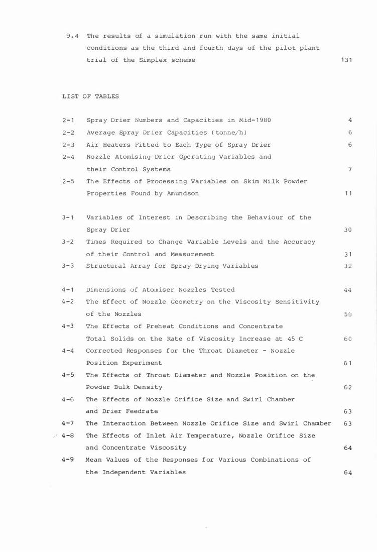
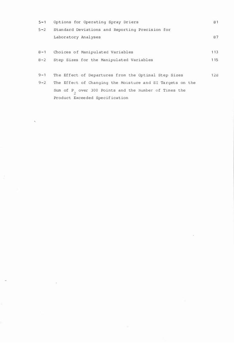


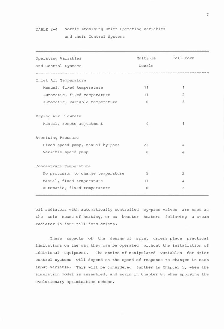


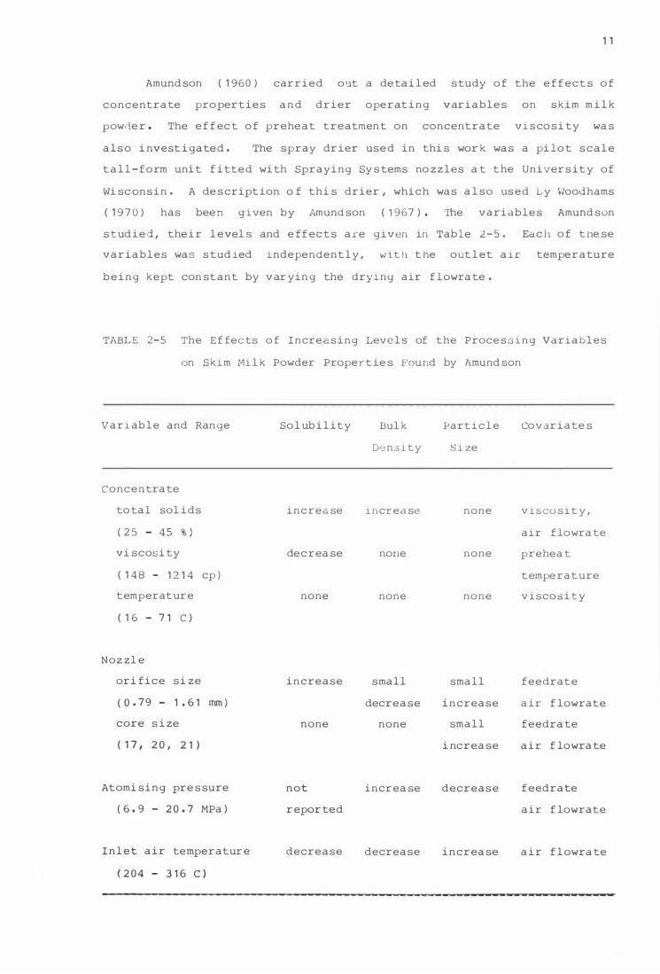


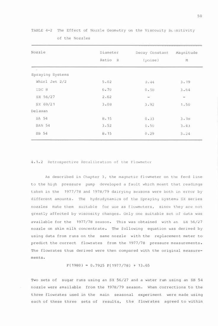

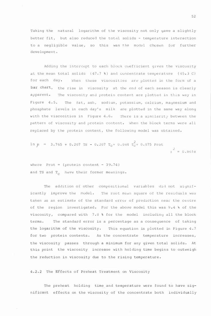


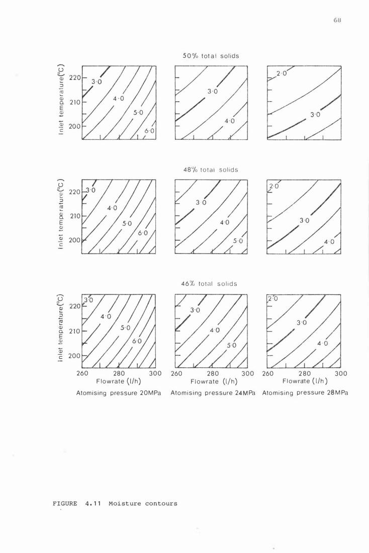

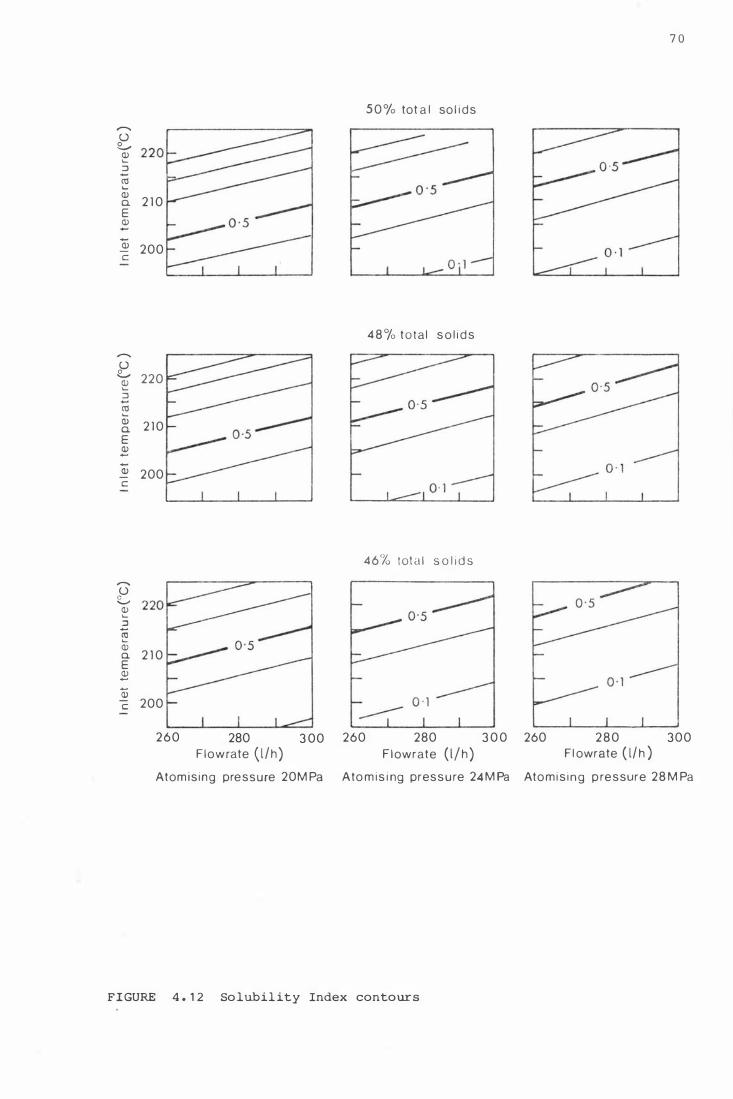


![GPG Gravity Spray Gun gpg.pdfThe GPG spray gun is a professional quality spray gun designed to comply with all global legislations. Trigger 12 bar [175 psi] ... Never use 1,1,1-Trichloroethane,](https://static.documents.pub/doc/80x56/610bfed5e0aa09342647c21f/gpg-gravity-spray-gun-gpgpdf-the-gpg-spray-gun-is-a-professional-quality-spray.jpg)


