Page 1
of Forming Processes in Three Dimensions
L. Giraud-Moreau, H. Borouchaki and A. Cherouat
Institut Charles Delaunay (FRE CNRS 2848)
University of Technology of Troyes
12 rue Marie Curie BP2060
10010 Troyes Cedex - France
[email protected]
Abstract. This article presents a remeshing procedure of thin sheets for numerical
simulation of metal forming process in three dimensions. During simulation of
metal forming processes, where large plastic deformations are possible, severe
mesh distortion occur after a few incremental steps. Hence an automatic mesh
generation with remeshing capabilities is essential to carry out the finite element
analysis. This paper gives the necessary steps to remesh a structure in finite ele-
ment simulation of forming processes. The proposed remeshing technique based
on geometrical criteria includes adaptive refinement and coarsening procedures. It
has been implemented with triangular and quadrilateral elements. The proposed
method has been integrated in a computational environment using the ABAQUS
solver. Numerical examples show the efficiency of the proposed approach.
sheet.
Keywords: Adaptive remeshing, forming process, geometrical error estimator, thin
1 Introduction
The finite element method has been very successful in the numerical
simulation of metal forming processes like deep-drawing, hydro-
forming or forging [1-2]. However, due to the imposition of large
A Remeshing Procedure for Numerical Simulation
Page 2
128 L. Giraud-Moreau et al.
plastic strains and friction, the finite element mesh representing the
workpiece undergoes severe distortion and hence it is necessary to
generate a new mesh for the deformed domain [3]. It is therefore
convenient to update the mesh in such a way that it conforms to the
new deformed geometry and becomes dense enough in the critical
region while remaining reasonably coarse in the rest of the domain.
The remeshing procedure must be automatic and robust. Several
remeshing methods have been proposed during the last years. Glob-
ally, three different types of adaptive remeshing strategies can be
distinguished: r-adaptivity, p-adaptivity and h-adaptivity [4-5].
Strategies based on r-adaptivity consist of keeping the number of
special grid points fixed, but allowing them to move into regions
where a finer spatial discretization is needed. This type of adaptation
is particulary powerful on problems where a large domain is needed
to capture a time varying solution which has steep slopes over only a
small fraction of that domain [6]. The remeshing techniques pre-
sented by Zienkiewicz et al [7], Fourment et al [8], Coupez [9],
Borouchaki et al [10] are based on the computation of a size map to
govern a global remeshing of the part at each iteration. Strategies
based on p-adaptivity consist of changing the degree of the interpo-
lating polynomials in appropriate regions of the mesh. This method
is preferred for (linear) smooth solutions or over subregions where
the solution is smooth [11]. Strategies based on h-adaptivity consist
of adapting the number of grid points and changing the mesh con-
nectivity. Grid points are added to areas where more accuracy is
demanded (the interpolation will be enriched) and can be deleted
where the solution is accurate enough. As part of these methods,
remeshing techniques based on the computation of a size map to
govern a global remeshing of the part at each iteration have been
proposed [7-10]. Cho and Yang [12] have proposed a refinement al-
gorithm based on h-adaptivity which consists in splitting each de-
formed element in two elements along an edge. This procedure drags
to the creation of small edges and consequently degenerates
Page 3
elements during repetitive refinement iterations. Moreover, all simi-
lar refinement methods only based on the break of edges lead to the
formation of small edges or poor shaped elements.
This paper presents a new remeshing technique for the numerical
simulation of thin sheet metal forming processes. This method is
based on a geometrical criterion. It is applied to computational do-
main after each small displacement step of forming tools. It allows,
in particular to refine the current mesh of the part under the numeri-
cal simulation of the forming process in the curved area with pre-
serving shape quality element and to coarsen this mesh in the flat
area.
The mesh refinement is necessary to avoid large element distor-
tions during the deformation. It ensures the convergence of the com-
putation and allows an adequate representation of the geometry of
the deformed domain. The mechanical fields are simply induced
from the old mesh into the new mesh.
The proposed remeshing method looks like to the remeshing
method presented by Meinders [13] in the case of a triangular mesh.
Compared to Meinders method, the proposed remeshing technique
generates a smaller number of elements, it has been implemented
with triangular and quadrilateral elements and a coarsening tech-
nique is considered, in addition to the refinement technique.
This paper gives the different steps of the proposed remeshing
method. Some application examples are presented in order to show
the pertinence of our approach.
The simulation of the forming process is based on an iterative proc-
ess. At first, a coarse initial mesh of the part is generated with trian-
gular or quadrilateral elements. At each iteration, a finite element
computation is then realized in order to simulate numerically the
forming process for a small displacement step of forming tools.
This displacement step must be sufficiently small with respect to the
specified minimal size of mesh elements.
2 General Remeshing Scheme
A Remeshing Procedure for Numerical Simulation 129
Page 4
130 L. Giraud-Moreau et al.
Then, remeshing is applied after each deformation increment, if nec-
essary, according to the following scheme:
coarsening procedure applied to elements which are in flat area,
iterative refinement to restore mesh conformity,
refinement procedure applied to elements which are in curved area
(the refinement is applied in the vicinity of nodes for which the
shape of the surface is changed and only if the minimal element
size is not reached),
iterative refinement to restore mesh conformity.
This process (simulation of the forming process for a small dis-
placement step of forming tools, remeshing of the part) is repeated
until the final tool displacement is reached.
The computation convergence is principally based on the mesh
refinement and coarsening procedures. The applied refinement must
in particularly not introduce a mesh distortion, which could increase
during iterations and stop the forming process simulation.
During the remeshing procedure, a geometrical criterion is used to
refine the current mesh of the part in the curved area, and to coarsen
this mesh in the flat area. For a given element, this geometrical crite-
rion represents the maximal angular gap between the normal to the
element and the normals at its vertices. An element is thus consid-
ered to be “curved” (resp. “flat”) if the corresponding angular gap is
greater (resp. smaller) than a given threshold (for example 8 de-
grees). The geometrical refinement and coarsening methods based
on the same geometrical criterion are thus consistent.
The normal vector at node P can be defined as the weighted av-
erage of the unit normal vectorsi
N (i = 1,..m) to elements sharing
node P:
2.1 Geometrical Criterion
Page 5
131
m
i
ii
m
i
ii
N
N
0
0(1)
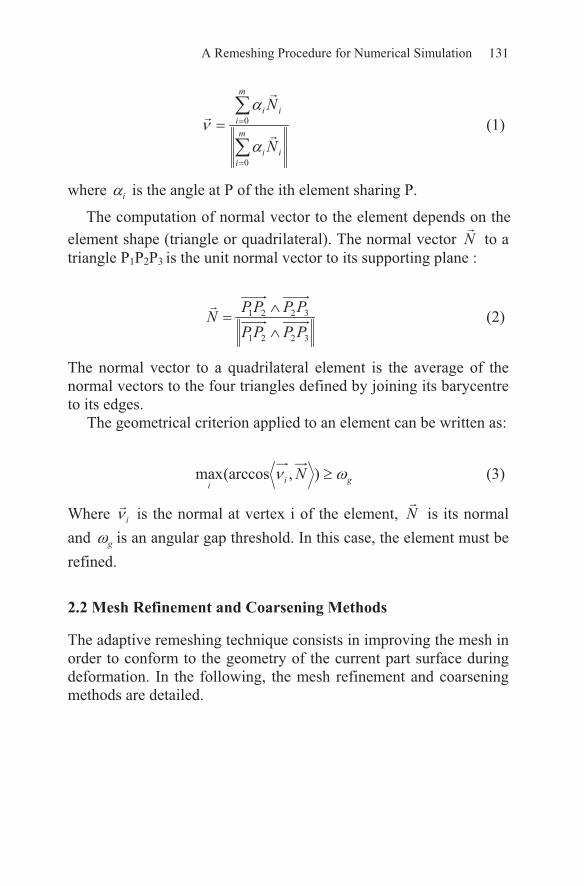
wherei is the angle at P of the ith element sharing P.
The computation of normal vector to the element depends on the
element shape (triangle or quadrilateral). The normal vector N to a
triangle P1P2P3 is the unit normal vector to its supporting plane :
3221
3221
PPPP
PPPPN (2)
The normal vector to a quadrilateral element is the average of the
normal vectors to the four triangles defined by joining its barycentre
to its edges.
The geometrical criterion applied to an element can be written as:
gii
N ),(arccosmax (3)
Where i is the normal at vertex i of the element, N is its normal
andg
is an angular gap threshold. In this case, the element must be
refined.
The adaptive remeshing technique consists in improving the mesh in
order to conform to the geometry of the current part surface during
deformation. In the following, the mesh refinement and coarsening
methods are detailed.
A Remeshing Procedure for Numerical Simulation
2.2 Mesh Refinement and Coarsening Methods
Page 6
132 L. Giraud-Moreau et al.
The refinement technique consists in subdividing mesh elements.
An element is refined if it is a “curved” element (geometrical crite-
rion). There is only one element subdivision which allows to pre-
serve the element shape quality: the uniform subdivision into four
new elements. In the case of a triangle, three new nodes are added :
one in the middle of each edge. In the case of a quadrilateral, five
nodes are added : one in the middle of each edge and one in the ele-
ment barycentre. Figure 1 shows the triangular and quadrilateral
element refinements.
After each refinement procedure, an iterative refinement to restore
mesh conformity is necessary. Indeed, after applying the subdivision
according to the geometrical criterion, adjacent elements to subdi-
vided elements must be modified. As the edges of the subdivided
elements are divided in two, there is a node in the middle of the
edges common to the subdivided element and its adjacent elements.
The mesh is then not conforming. To retrieve the mesh conformity,
adjacent elements to subdivided elements must be also subdivided.
This last subdivision can not be a homothetic subdivision in four
elements because it would result in the systematic homothetic subdi-
vision of all mesh elements.
There are three different configurations for adjacent elements
which must be subdivided in order to ensure the mesh conformity:
no edge is saturated (i.e. containing a new added node),
only one edge is saturated,
at least two edges are saturated.
Fig. 1. Triangular and quadrilateral element refinements
Page 7
133
Depending on the configuration, a subdivision is applied if neces-
sary. In the first case (no saturated edge), the element is not subdi-
vided and is not modified. In the second case (one saturated edge), a
triangular element is subdivided in two triangles and a quadrilateral
element in three triangles (see figure 2). This subdivision allows to
stop the propagation of the homothetic subdivision. In the third case,
if all the edges are saturated the element is subdivided in four homo-
thetic elements. Otherwise, in the case of triangular elements (hav-
ing two saturated edges), all possible subdivisions lead to the forma-
tion of poor shaped elements (stretched elements). It is then
necessary to add a new node in order to subdivide also this element
into four homothetic elements (see figure 3). In the quadrilateral
A Remeshing Procedure for Numerical Simulation
case, when only two edges are saturated and are adjacent, the quadri-
lateral is subdivided in four triangles (see figure 4). This subdivision
allows to stop the propagation of the homothetic subdivisions. In the
other cases, the element is subdividing into four homothetic quadri-
lateral elements (see figure 5) by adding nodes in the middle of no-
saturated edges and in the barycentre of the element.
This refinement procedure is iteratively applied until no new node is
added.
Fig. 2. Subdivision of elements with one saturated edge
Fig. 3. Subdivision of triangle with two saturated edges
Page 8
134 L. Giraud-Moreau et al.
From an algorithmic point of view, the mesh is composed of two
types of element: ordinary and extraordinary. An ordinary element is
a triangle or a quadrilateral without saturated edges (see figure 6).
An extraordinary triangle is a triangle with one and only one satu-
rated edge. An extraordinary quadrilateral is a quadrilateral with
only one saturated edge or two adjacent saturated edges. Figure 7
shows extraordinary triangle and quadrilaterals. The remeshing algo-
rithm must take into account these two element types. During the re-
finement operation, the geometrical criterion is applied to elements
of both types. An ordinary or extraordinary element which is curved
is then subdivided into four ordinary elements. After this operation,
all ordinary elements with at least two saturated edges, except the
case of two adjacent edges for quadrilateral elements, are iteratively
subdivided into four ordinary elements. Then, all the elements with
at least one saturated edge are transformed to extraordinary elements
and the other elements remain unchanged.
At the end of the refinement operation, for the mechanical com-
putational purpose, the extraordinary elements of the resulting mesh
are transformed : an extraordinary triangle is divided in two trian-
gles, an extraordinary quadrilateral with one middle node is divided
in three triangles and an extraordinary quadrilateral with two middle
nodes is divided in four triangles.
Fig. 4. Subdivision of quadrilateral element with two adjacent saturated edges
Fig. 5. Other cases of subdivision of quadrilateral element
Fig. 6. Ordinary elements
Page 9
135A Remeshing Procedure for Numerical Simulation
Fig. 7. Extraordinary elements
The coarsening technique is the reciprocal operation of the refine-
ment procedure. It can only be applied to a set of four ordinary ele-
ments, called associated elements, obtained during a homothetic
element refinement. Thanks to the coarsening technique, the initial
element is restored when the area in which this element belongs, be-
comes flat (see figure 8).
Fig. 8. Triangular and quadrilateral elements coarsening
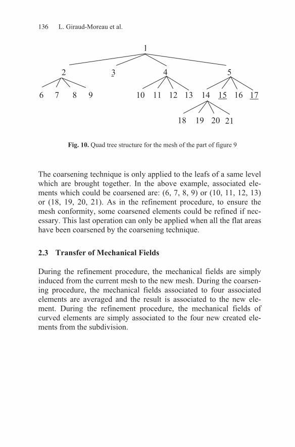
A quad tree structure can be considered to coarsening the mesh of
the part. This structure allows to quickly localize associated ele-
ments. Each root of the tree is an element of the initial mesh and
each edge is an intermediate element created during the refinement
procedures. The leafs of the tree are elements of the current mesh
and are brought together if they are associated. Figure 10 presents
the quad tree structure associated to the mesh of the part on figure 9
at iteration 3. Elements whose number is underlined, are extraordi-
nary elements.
Fig. 9. Example of adaptive remeshing during three iterations
10 11
1213
15 16
1714
9
6 7
8
15 16
17
10 11
121318 19
21 20
Iteration: 0 Iteration: 1 Iteration: 2 Iteration: 3
Page 10
136 L. Giraud-Moreau et al.
The coarsening technique is only applied to the leafs of a same level
which are brought together. In the above example, associated ele-
ments which could be coarsened are: (6, 7, 8, 9) or (10, 11, 12, 13)
or (18, 19, 20, 21). As in the refinement procedure, to ensure the
mesh conformity, some coarsened elements could be refined if nec-
essary. This last operation can only be applied when all the flat areas
have been coarsened by the coarsening technique.
2.3
During the refinement procedure, the mechanical fields are simply
induced from the current mesh to the new mesh. During the coarsen-
ing procedure, the mechanical fields associated to four associated
elements are averaged and the result is associated to the new ele-
ment. During the refinement procedure, the mechanical fields of
curved elements are simply associated to the four new created ele-
ments from the subdivision.
1
2 3 4 5
6 7 8 9 10 11 12 13 14 15 16 17
18 19 20 21
Transfer of Mechanical Fields
Fig. 10. Quad tree structure for the mesh of the part of figure 9
Page 11
137
3.1
An early application of adaptive mesh refinement was the simulation
of 3-D sheet metal stamping example (Benchmark square box of
Numisheet’93). According to Onate et al. [14], the geometric data of
the square cup are: drawing depth 40 mm, sheet dimensions
150 150 mm2, thickness h
0= 0.78 mm, friction coefficient between
the sheet and rigid tools is assumed to be = 0.144 and the blank-
holder force F = 19600 N. The material model used is an isotropic
elastoplastic von-Mises model with multi-linear isotropic hardening
approximating a power law yield stress curve defined as
2637.0)07127.0(29.567
p
. The punch velocity is 20 mm/s and
its stroke is 80 mm. The tools (punch, die and blank-holder) are sup-
posed rigid and modeled by discrete rigid surfaces. Two examples
are presented: the first example concerns the stamping of square
sheet in which the angle between initial sheet plane frame (X,Y)
and the tools orientation (x,y,z) is = 0° (see Figure 11a) and the
second concerns the stamping of square sheet with = 45° (see Fig-
ure 11b). In these two cases, the solver 3D ABAQUS/EXPLICIT
has been used. The element size adaptive discretization of the de-
formable sheet uses hmin = 0.75 mm, geometrical criterion = 8°.
Meshes adapted to the part curvature corresponding to different
punch displacement (u = 6, 15, 24, 30, 36, 45 and 48 mm) are shown
in Figures 12 to 18 for = 0° and = 45°. We can note that, the ini-
tial blank sheet is computed using an initial coarse mesh (100 quad-
rilateral elements), the mesh is again refined uniformly and the adap-
tive mesh refinement procedure is activated where elements are
created automatically in regions of large curvature to even more ac-
curately represent the complex material flow (large stretching)
around the punch and die radii. The final contour of the sheet for 60
mm of punch displacement is presented in Figure 22 for = 0° and
in Figure 23 for = 45°. We can note the final shape of the sheet is
completely different due the initial sheet orientation.
A Remeshing Procedure for Numerical Simulation
3 Numerical Examples
Sheet Metal Stamping
Page 12
138 L. Giraud-Moreau et al.
(a) = 0° (b) = 45°
Fig. 11. Tools and initial sheet orientation
Fig. 12. Displacement u = 6 mm
Fig. 13. Displacement u = 15 mm
Fig. 14. Displacement u = 24 mm
xy
Y
XY X
xy
Page 13
139A Remeshing Procedure for Numerical Simulation
Fig. 15. Displacement u = 30 mm
Fig. 16. Displacement u = 36 mm
Fig. 17. Displacement u = 45 mm
Page 14
140 L. Giraud-Moreau et al.
Fig. 18. Displacement u = 48 mm
Fig. 19. Final shape for = 0°
Fig. 20. Final shape for = 45°
Page 15
141
3.2
The second example is the crushing of a thin cylinder. The cylinder
blank has initially 140 mm length, 44 mm diameter and 0.5 mm
thickness. The initial mesh of the cylinder is constituted by 2048
quadrilateral sheet finite elements. Two concentrate loads diametri-
cally opposite was prescribed using a linear ramp to simulate the
crushing operation. The deformation evolution of the blank is illus-
trated in Figure 21. Here, the mesh refinement is localized on large
deformed blank areas. The final mesh of the blank contains 30301
quadrilateral and 26714 triangular elements.
A Remeshing Procedure for Numerical Simulation
Crushing of a Thin Cylinder
Page 16
142 L. Giraud-Moreau et al.
4 Conclusions
The different steps necessary to the remeshing of the computation
domain in large elastoplastic deformations in three dimensions have
been presented. The proposed adaptive remeshing technique is based
on refinement and coarsening procedures using ageometrical crite-
rion. This approach has been implemented with triangular and quad-
rilateral elements in the ABAQUS code. Numerical simulations of
thin sheet metal forming process in three dimensions have validated
the proposed approach and proved its efficiency. The extension in
three dimensions for massive structure metal forming is currently
under progress.
Fig. 21. Deformed cylinder for different crushing step
References
1. H. Borouchaki, A. Cherouat, K. Saanouni, A. Cherouat and P. Laug,
“Remaillage en grandes deformation. Applications à la mise en forme de
structures 2D”, Revue Européenne des éléments finis (to appear), 2002.
Page 17
143A Remeshing Procedure for Numerical Simulation
2. K. Saanouni, A. Cherouat and Y. Hammi, “Optimization of hydroforming
processes with respect to fracture”, Esaform, Belguim, 1, 361-364, 2001.
3. P. Ladeveze and J.P. Pelle, “La maîtrise du calcul en mécanique linéaire et
non linéaire, études en mécanique des matériaux et des structures”, Hermès,
Paris, France, 2001.
4. D. Djokovic, “Splines for approximating solutions of partial differential equa-
tions”, Ph.D. Thesis, University of Twente, Enschede, ISBN 90-36510511,
1998.
5. A. Huerta, P. Diez, A. Rodriguez-Ferran, “Adaptivity and error estimation”,
Proceedings of the 6th
International Conference on Numerical Methods in In-
dustrial Forming Processes, J. Huétink and F.P.T. Baaijens (eds), Balkema,
Rotterdam, 63-74, 1998.
6. R. Drake, V.S. Manoranjan, “A method of dynamic mesh adaptation”, Int. J.
Num. Meth. Eng., 39, 939-949, 1996.
7. O. C. Zienkiewicz and J. Z. Zhu, “Adaptivity and mesh generation”, in Int. J.
Numer. Methods Eng. 32, 783-810, 1991.
8. L. Fourment and J.-L. Chenot, “Adaptive remeshing and error control for
forming processes”, Revue européenne des éléments finis 3, 2, 247-279,
1994.
9. T. Coupez, “Génération de maillage et adaptation de maillage par
optimisation locale”, Revue européenne des éléments finis 9, 4, 403-422,
2000.
10. H. Borouchaki, A. Cherouat, P. Laug and K. Saanouni, “Adaptive remeshing
for ductile fracture prediction in metal forming”, C.R. Mecanique 330, 709-
716, 2002.
11. Y. Li, I. Babuska, “A convergence analysis of a p-version finite element
method for one-dimensional elastoplasticity problem with constitutive laws
based on the gauge function method”, J. Num. Anal., 33, 2, 809-842, 1996.
12. J.-W. Cho and D.-Y. Yang, “A mesh refinement scheme for sheet metal form-
ing analysis”, Proc. of the 5th International Conference, NUMISHEET’02,
307-312, 2002.
13. T. Meinders, “Developmsents in numerical simulations of the real life deep
drawing process, Ph.D. Thesis, University of Twente, Enschede, ISBN 90-
36514002, 2000.
14. E. Onate, J. Rojek, C. Garcia Garino, Numistamp: "A research project for as-
sessment of finite element models for stamping process", Journal of Materials
Processing Technology 50, 17-38, 1995.