NASA-CR-171838 19850008985 A Rep'roduced Copy OF Reproduced for NASA by the NASA Scientific and Technical Information Facility 1111111111111 11111111111111 I111I 1I11I 11111111 NF01599 FFNo 672 Aug 65 ! ' " !"j ". j J "1 l.ANGLEY RESEARCH CENTER L18rtARY, NASA HAMP-tOtl. YJRGlWA https://ntrs.nasa.gov/search.jsp?R=19850008985 2020-08-04T03:43:41+00:00Z
Transcript
NASA-CR-171838 19850008985
A Rep'roduced Copy OF
Reproduced for NASA
by the
NASA Scientific and Technical Information Facility
(bASA-CR-171UJ8) DES1~h A~D lEST OF A fLUB N8S-17254 CliAUNiL MCT~h fCE EL1C!ECMIChAN1CAL FLIUill ~CNTbCL Ae1UA1ICb Fin~l Ee~oLt (Suust~~LJ Ener.qy Sys~ellls) .. ~45. j. he A 11/I1F AO 1 UncldS
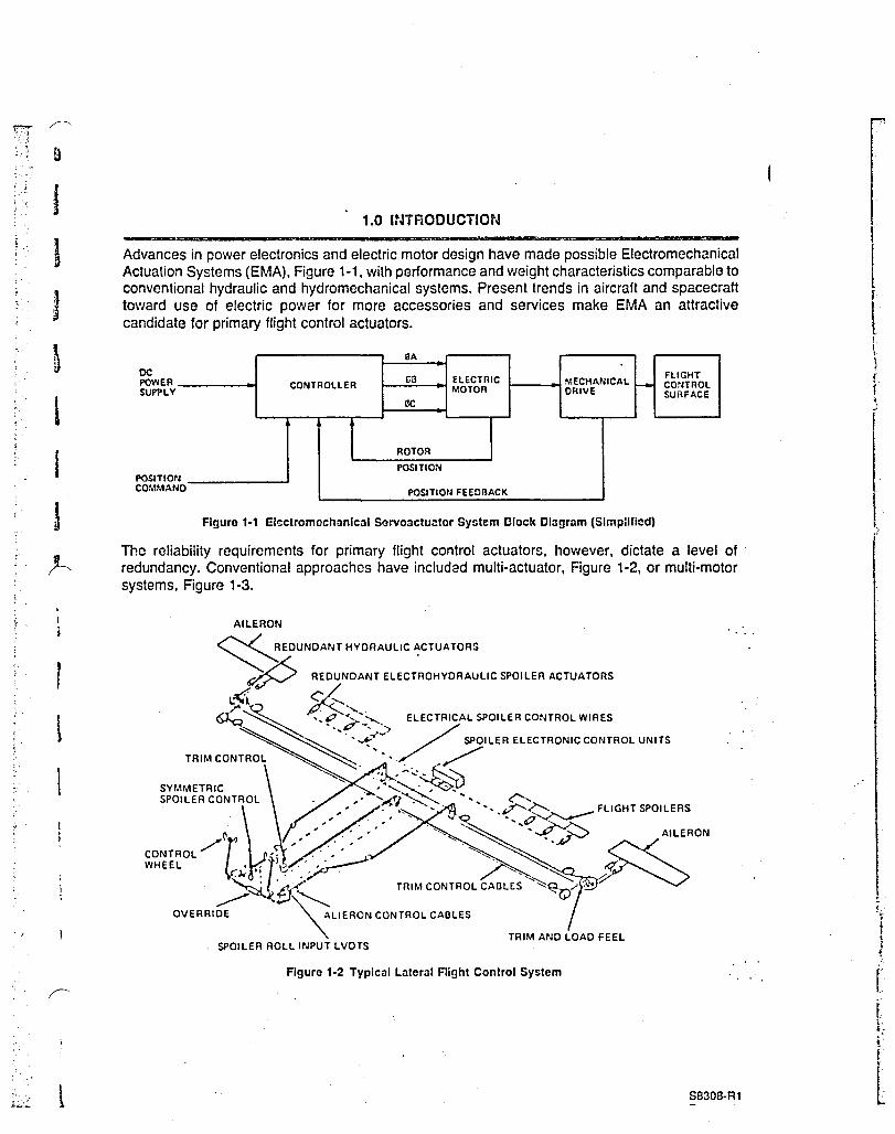
Advances in power electronics and electric motor design have made possible Electromechanical Actuation Systems (EMA). Figure 1-1. with performance and weight characteristics comparable to conventional hydraulic and hydro mechanical systems. Present trends in aircraft and spacecraft toward use of electric power for more accessories and services make EMA an attractive candidate for primary flight control actuators.
DC POWER SUPi>LY
POSITION COMMAN 0
SA
[;\l ELECTRIC MECI1ANICAL CONTROLLER -MOTOR ORIVE IlC
The reliability requirements for primary flight control actuators. however. dictate a level of ' redundancy. Conventional approaches have included multi-actuator. Figure 1-2. or multi-motor systems. Figure 1-3.
AILERON
~EDUNDANT HYDRAULIC ACTUATORS
~ REDUNDANT ELECT~OHYDRAULIC SPOILER ACTUATORS
~~.~ ~,. ~ .. ~,>::---.') ELECTRICAL SPOILER CONTROL WIRES
" ~ "~~~ / SPOILER ELECTRONIC CONTROL UNITS
TRIM CONTRO, ~. ./ / SYMMETRIC '" . :'-..:...~~ SPOILER CONTROL . .. .... ""'V">.......~ ~" <":....
Figure 1·3 Space Shuttle Rudder/Speedbrako Schematic
To achieve the full potential of EMA technology, it is desirable to obtain the required redundancy' with a multi-channel motor which could electromagnetically sum the torque of the individual channels on a single rotor, Figure 1-4. Complex mechanical gearing arrangements could then be eliminated.
To reduce this concept to practical application requires knowledge of the failure modes and effects and innovative approaches to control and redundancy management.
As the first step in this effort. NASA-JSC and Sundstra"d Advanced Technology Group undertook a joint program to design, develop and test a highly reliable. lightweight. multi-channel motor. This program was conducted under contract NAS-9-16535.
This project concentrated on establishing a suitable electromagnetic torque summing approach to flight control system redundancy. The objective was to design. fabricate. and test a brushless dc .. motor with four-channel/two fault tolerant redundancy. This motor provided the means for' validation of the analytical models and permits future development of a compatible four-channel control technique.
S8308-R1 Page 1·2
.:.
\' ., <
. ~:
I '
'(. : ~ " ..
:." .
. ~ ..
.. ,'
k::~;
OUTPUT
OUTPUT SHAFT
SHAFT (THRU 4 ROTORS)
OUTPUT SHAFT (THRU 2 ROTORS)
SINm.E STATOR ASSEMBLY
-c:.4SEPARATE WINDINGS EACH A SINGLE PHASE ITVP N PHASES)
Within this context, several specific objectives were defined:
1. Establish a Preferred Motor Concept - With emphasis on failure modes and effects, different mechanical arrangements were evaluated and a preferred concept selected .
2. Minimize Weight of Preferred Concept - The weight of the preferred concept was evaluated with respect to performance, reliability, and efficiency. Electromagnetic design parameters were traded to achieve a suitable balance of these characteristics.
3. Validate Electrical Performance Model - Single-channel tests of the motor characterized its performance and were used to validate the design models.
In achieving these objectives, the intent of this project was to demonstrate the feasibility of electromagnetic torque summing and establish the credibility of weight and performance
S8308-R1 Page 1-3
....
,~
I
I I
! I I
I I I
f j • j 1 'I
f I t 1
1 j ]
1 J
J j ... j '. ,j "
rl If ;j
I '0'
j ' 0,.
'~,
~
B
u
n !~
f n D "
g
9 r--......
D
D D j:.
~
B ~
D
~ (~
D I' I
ill "
predictions. In conjunction with this work, NASA-JSC separately funded the development of finite element electromagnetic performance models. The combination of these analytical techniques, the characterization data obtained from motor tests, and the availability of a four-channel motor provide the foundation for the future development of a compatible control strategy.
S8308-R1 Page 1-4
"'I ; i '! ) '.0 , .,
'1 f ~ "
"-
~.
-i --,~
-,
"
;.: " 0
, ,;
-.~~
~ , ,"''If:.,. ~; ..
,\
~} ~ ~~
i
>':' , , ,~
~',
, j .;;
.~:.
, . '; .
, '":-;t:
'1 , ;'~ /.J':
" "I
'0
: ,,' .t
. i .. ..
~n~, .~:-~ .
t~J.
,1
:j
'J ." LJ
~
'] ! ~ .. ~
'f}
, ~ ~ I "
. r :i U
~ :~r'\
"! ." !
,
• I
t , , <
"'~
J
'-I, " ;
:L L '
'~
J,
,4 'f.,· .... ;
i
l r.' J g' ., .'( J t: '
'~ ,
't,:\
~ ',~
,
I I , I i 1 1 l 1 > 1 .
1
r ~ ! j i j .. ,
,1 .1
J J
J '. ,
:1 i J .~
'I .. ia
] J .t ~
'j :J '~ .
1 :l ] , " ~'l - : .:~ ~z..:....:
~
g .'
n ..
n n B
~
~ g r---'" b
Q
B
8 n ~
~
n :(
r fa
.H
2.0 SUMMARY -A four-channel motor, capable of sustaining full performance after any two credible failures was successfully designed, fabricated, and tested. Configure~ as illustrated in Figure 2-1, the design consisted of a single samarium cobalt permanent magntJt rotor with four separate three phase windings arrayed in individual stator quadrants around the periphery.
Trade studies' which culminated in this design established the sensitivities of weight and penormance to such parameters as design speed, winding pattern, number of poles, magnet. , . configuration and strength. With this information, individual design details were selected to . provide a reasonable balance between weight and performance. The resulting motor, at 33.31 pounds, achieved a project goal, bettering a 34 pound maximun. established by comparison to comparable hydraulic systems. With a demonstrated efficiency of 92.9% at a design point of 4333 rpm, 17.2 hp, the motor also achieved the goal of 90% minimum efficiency. The prototype motor is shown in Figure 2-2.
Manufacturing techniques refined in the cunstruction of this unit demonstrated that electromagnetic torque summing is a practical concept. Methods of coil winding and insertion pIUS rotor fabrication techniques provided a light, compact assembly without exotic and expensive processes.
Equally significant, testing demonstrated excellent 'llectromagnetic separation among !he individual channels. Performance was virtually unaffected as channels were added or subtracted from the circuit. Extensive static and dynamic data were developed. Included in the Appendix t6 this report, these data provide the essential information necessary to design a compatible four-channel controller and ultimately bring an &Iectromechanical flight control system to fruition.
The approach used in this project is summarized as follows:
i) ESTABLISH REQUIREMENTS - Sundstrand and NASA-JSC jointly reviewed the functional requirements of an EMA system, assessed their influence on motor desiyn and selected a working set of design criteria.
ii) ESTABLISH PREF!=RRED GEOMETRY - A variety of configurationz were conceived and compared, establishing a preferred mechanical arrangement.
iii) DEFINE POINT OF DEPARTURE DESIGN - A detailed design of the prci'~rred geometry was executed using historical information to select individual part configurC'dons. "
iv) ESTABLISH POINT OF DEPARTURE PERFORMANCE - In-depth analyses were conducted for the preferred geometry to fully define its predicted performance.
v) ITERATE ON POINT OF DEPARTURE - Individual deSign parameters were varied to develop sensitivity information enabling a rUined final design to b) established.
vi) FABRICATE FINAL DESIGN - One motor was built. Design changes necessary for manufacturing reasons were factored into the analyses.
vii) TEST FINAL DESIGN MOTOR - Motor and single channel motor/controller tests were conducted to confirm and correct the . analytical techniques and provide a data base for controller development by NASA.
viii) NASA-JSC TESTING - The motor was provided to N.ASA-.ISC for planned performance, . and failure mode evaluation testing.
The objective of the design studies was to establish a design which offered a reasonable balance of the desired criteria. Trades were conducted to define ?, preferred geometry which was then optimized. 'Variables such' as magnet material, lamination material, number of poles, rotor construction, design speed and winding pattern were considered.
The method employed entailed establishing the preferred arrangement using reliability criteria. The details of this configuration were then selected, based on prior experience, to establish a point of departure design. This baseline was analyzed in depth to fully characterize its performance and physical properties.
Next, each parameter was varied individually by carrying out complete alternate motor designs, calculating the resulting performance and comparing to the baseline. After all the variables had been evaluated in this manner, a final motor design was performed using the optimum value for each parameter. This version was later fabricated to assess the accuracy of the predictions, to validate the models and to provide a tool for further system development.
A flow diagram of the trade studies is found in Figure 4-1.
4.1 REQUIREMENTS
The design for the motor is based on the Space Shuttle inboard elevon performance requirements, Figure 4-2. The Space Shuttle requirements were chosen because, at the time, interest in an electric Orbiter offered a likely opportunity for a near-term demonstration of this technology.
Fault Tolerance and Torque'vs.'Speed
The two-fault tolerant requirement dictates that the actuator's motor provide full performance even after two credible failures. A further stipulation for safe operation at reduced performance with any three credible failures was also imposed, in essence dictating a four-channel motor. Quadruple redundancy is compatible with the Shuttle flight control system of four general purpose computers with four reconfigurable data strings.
The resulting actuator, therefore, requires the torque vs. speed characterhitics illustrated in Figure 4-3. Note that to provide this full performance with only two healthy motor channels requires that each channel be capable of supplying one-half full actuator output power plus one-half of any losses engendered by the failed channels. Theoretically then a fully healthy motor would be capable of supplying, at least instantaneously, the torque shown in Figure 4-4.
The four channel concept thus carries the potential for overdriving the actuation system and perhaps damaging structure. Control of this situation must be considered in ensuing system definition activities.
Duty Cycle
The duty cycle defined in the contract statement of work is shown in Figure 4-5. Representing original Orbiter design criteria, this cycle comprises approximately 2000 watt-hours .
REQUIREMENTS DEFINITION
V
CONCEPT SELECTION
V BASELINE DESIGN
V SPEED TRADE STUDIOS OSPEED VS WEIGHT o SPEED VS DYNAMIC PERFORMANCE o SPEED VS THERMAL CAPABILITY
t ROTOR CONFIGURATION TRADE STUDY oTANGENTIAL VS RADIAL MAGNETS
., WINDING PATTERN TRADE STUDY oDELTA VS WYE
V NUMBER OF POLES TRADE STUDIES o NO POLES VS WEIGHT o NO POLES VS EFFICIENCY
~ MAGNET MATERIAL TRADE STUDIES oMAGNET STRENGTH VS WEIGHT OMAGNET STRENGTH VS EFFICIENCY
t WEIGHT VS EFFICIENCY TRADE STUDY o LAMINATION MATERIAL
V FINAL DESIGN
Figure 4·1 Trade Study Flow Diagram
S8308·R1
, -
~ '. 'i r :f. L' , ~. ;
.500 iii ..J I
Z
co (:) ... X
.-Z w :: 0 :: w Cl Z :I:
o
.. __ . _________________ ._~I ... W • .. ~
INPUT VOLTAGE STROKE NO LOAD VELOCITY STALL LOAD DYNAMIC PERFORMANCE RELIABILITY
Figure 4-2 Space Shuttle Inboard Glavon Requirements
4, 3 OR 2 CHANNELS OPERATING
20
HINGE RATE (DEGRESS/SEC)
Figure 4-3 Motor Speed-Torque Requirements
30
I t i t i,
m ··,-G
o
iii ..I I
Z
to b .500 ... ~ I-Z w :: 0 :: w (!) Z :r;
iF .300 o ... X a:I ..I
Z .:. .200 I-Z w :: o :: ~ .100 z :r;
o
4 CHANNELS OPERATING
3 CHANt,lELS OPERATING
2 CHANNELS OPERATING
20
HINGE RATE (DEGREES/SEC)
Figure 4-4 Motor Speed-Torque Capcbilities
.204 .300
.156 .192
I .-.05 •
.025 +12;y/ISEC .25 HZ
+2o/SEC I .~#
-" . 5 10 15 20
TIME (MINUTES)
Figure 4-5 Duty Cycle
.-.
25
o
. 30
.120 I +250 /SEC •• 25 HZ
30
S8308-R1 Page 4-4
-I f' ~ ,
. "
~.
I~'~ ~.:~ ~ ~ :
~, Ll
At the time of this project, data from initial flights were revealing a large degree of conservatism in that value. Sufficient capability was anticipated to require no more than 500 watt-hours.
In order not to penalize this design study by using overly conservative criteria, NASA-JSC and Sundstrand jOintly redefined the duty cycle. The resulting cycle, summarized in Table 4-1 on a per channel basis, was predicated on the following:
1. Elevon hinge moment and rate using STS-1 data and three sigma winds.
2. Approximately 500 watt-hours total energy.
3. At least one maximum power point in each flight regime.
4. Output horsepower less than 1.5 horsepower 98% of the time.
5. Nine minutes of surface holding against inertia loads, assumed to be equal to 5% of the maximum load, during the initial phase of de-orbit prior to entering the atmosphere.
Table 4-1 Derived Single Channel Duty Cycle
Cycle Duration, Motor Power, Surface Rate, Motor Speed Number Minutes Horsepower Degrees/Sec. RPM Remarks
1 9 Holding 0 0 Holding 12,500 in·lb/GR··
2 17.5 0.3 5 1666
3 0.5 2.3 5 1666
4 7.5 0.3 13 4333
5 0.5 10.0 13 4333 Max. Hinge Moment
6 3.5 0.3 20 6666
7 0.5 10.0 20 6666
8 1.5 0.3 30 10.000
9 0.5 10.0 30 10,000 Max. Surface Rate
• • Based on 10,000 RPM Motor •• Gear Ratio (GR) = 2.000:1 for 10,000 RPM Motor
4.2 EVALUATION CRITERIA
A principal emphasis of this project was to ascertain the realistic weight savings which could be anticipated with electromechanical technology. For that reason, all design options were compared primarily on the basis of their effect on motor weight.
However, from an overall vehicle perspective, the lightest actuator may not yield the lightest system. If a heavy battery was the power source, for example, the motor would be only a small percentage of system weight. It would thus be advantageous to emphasize efficiency in the motor design to lower battery weight. For this reason, motor efficiency was the second criteria used for evaluating design options.
The theme which pervaded the trades then was to strive for the lightest design which would satisfy a minimum efficiency. Having selected candidates on this basis, a final evaluation of weight vs . efficiency was made to ascertain if efficiency gains would warrant some weight growth. The project goal was to produce a motor no heavier than "34 pounds with a 90% minimum efficiency at the design operating point.
S8308-R1
~'1
,"r'~ n,' '1 H J 1
'1' ,',
,,'
"~
j ":1
, .
o n
f\
~
ill
r u
U H
/ ','
,
4.3 CONTROL CONSIDERATIONS
Although the primary emphasis of this project was development of a four channel motor, the interrelationship of the motor and its controller required that some control method be assumed. The following paragraphs describe the control strategy that was envisioned. Note that these assumptions relate to providing compact and efficient control of the actuation functions and do not addres~ redundancy management. How faults are detected and controlled is the subject of futuer ' NASA-JSC activity.
Figure 4-6 is a block diagram of the actuation system. The controller converts the 270 volts dc to three-phase power suitable for driving the motor. It consists of an inverter and associated control electronics that process the commanded position, the rotor position, and the actuator position information to suitably switch the inverter.
POWER SUPPLY
N POSITIO COM MAN D
270VDC
A
CONTROLLER ¢B
MOTOR
¢c
ROTOR POSITION
LINEAR POSITION
Figure 4-6 Actuation System Block Diagram (Single Channal)
MECHANICAL DRIVE
LVDT ' EXITATION'
A voltage source, six-step inverter was selected because it is smaller and lighter than a current source inverter and is more suitable for pulse width modulation (PWM) control.
As shown in Figure 4-3, the motor must produce constant horsepower from the maximum speed down to 43% of the maximum speed. This can be accomplished by holding the commutation angle constant. However, the motor power factor and current will vary as the speed varies.
To minimize controller current, it is desirable to have the same motor current at the extreme speeds. This can be achieved by designing the motor such as to have a leading power factor at the maximum speed and a lagging power factor of the same magnitude at the lowest speed. The power factor depends on the ratio of the speeds, the higher the speed rar.ge, the lower the power factor. At the intermediate speeds, the power factor is always greater than the value at the extreme speeds as is the motor current. The motor design was based on this concept and optimized for operation at the extreme speeds.
For output powers less that full output power at speeds down to 43% of the maximum 'speed, reducing the commutation angle will reduce the output power since the output power is proportional to the sine of the commutation angle. Below 43% of the maximum speed, the outpiJt power can be controlled by simultaneously varying the commutation angle and the input voltage. PWM is used to control the input voltage.
More detail on the assumed control scheme is found in Appendix B. S8308-R1 Page 4·6
/ ' /
/ , ,/
j i, 1 I,
'. ! ! ) " :-, . ~
i 1" .
I" ~ ~. ~
?'-.. l , "
t
, ; '..;.
1
\
1
, t
~',
I i
4.4 DESIGN PROCEDURE
Two Sundstrand developed computer programs were used to design the brushless dc motor options and calculate performance.
The first program calculate~ the motor flux densities, back EMF, winding resistance, winding inductance, and other basic motor parameters from the motor dimensions, number of turns, wire size, permanent magn'et characteristics, etc.
The second program calculates the motor losses, torque, power factor, efficiency, current and the transistor currents. The inverter and motor are represented by an electrical network model and the motor performance is calculated by solving the networl< nonlinear differential equations.
4.5 SELECTION OF THE PREFERRED GEOMETRY
A variety of mechanical arrangements can be envisioned to provide a motor with four channel capability. For the purpose of this study, the six configurations shown in Figures 4-7 through 4-12 were selected as representative of the most likely approaches.
Single rotor concepts (Figure 4-7) are generally lighter and do not suffer from critical spr.ed problems. Multirotor designs (Figure 4-8) offer better fault isolation and greater torque to inertia ratio but have mora parts plus critical speed limitations. The concept in Figure 4-9 represents a combination of the single and multirotor approaches.
OUTPUT SHAn·
OUTPUT SHAFT (THRU 4 ROTORS)
SINGLE STATOR ASSEMBLY
L- 4 SEPARATE WINDINGS EACH A SINGLE PHASE (TVP N PHASES)
Figure 4-7 Four Channel Concept A
' ..
STATOR ASSEMBLY (TYP 4 PLACES)
ROTOR #3
1Cli---1 STATOR WINDING (TYP N PHASES) 4 PLACES
Figure 4-6 Four Channel Concept B sa30a·R1 Page 4-7
"
--i;
.' ;
•
I "
B o o
(\
~
B
m
B 9 11. 1]
_.-,--STATOR ASSEr.1BLY (TYP 2 PLACES)
'------2 STATOR WINDINGS (TYP fJ PHASES) 2 PLACES
Figure 4-9 Four Channel Concept C
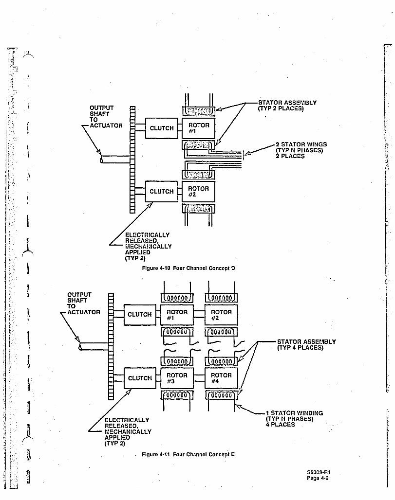
Multishaft approaches, shown in Figures 4-10 through 4-12, have the drawback of needing clutch mechanisms, but afford more straightforward methods of redundancy mCillagement.
In choosing among these options, mechanical and reliability criteria were applied. Mechanical considerations included qualitative assessment of complexity, volume, weight, and performance capability. Reliability considerations addressed thA ability to provide two fault tolerant performance. This included an evaluation of the ability of each configuration to isolate faults and prevent subsequent propagation to secondary failures. The nature of likely failure modes and their implications to overall system architecture were also considered.
The above considerations indicated the single rotor configuration, Figure 4-7, offered the best design solution. As a further refinement, several stator options for this configuration were conceived. These included intertwining the windings of the individual channels, completely· separating them, or partially overlapping them. The four quadrant geometry shown in Figure 4-13 was selected as offering the best isolation without affecting performance. Thus, the preferred concept is a single rotor geometry with a four quadrant stator.
As noted, dual fault tolerance requires two healthy channels to carry half the output load plus half any losses accruing to faults. Having selected a preferred geometry, it was then necessary to assess the probable failure modes, estimate the resulting additional losses, and thus establish the sizing criteria for the indiv!dual channels.
Mechanical failure modes are straightforwardly controlled with multipe rotating surfaces, dual retaining devices, generous structural margins of safety, etc. All probable modes entail very small additional losses.
Electrical failures can be generaily grouped as open circuits or short circuits. As the scope of this· project was directed to permanent magnet brush less de motors, the presence uf permanent magnets enables the motor to also perform as a generator. This fact causes short circuit tailures, which present fault current paths, to produce considerable retarding torque. Compensating for two faults of this nature could result in an excessively large motor.
In evaluating this scenario, any failure or failure combination with a probability of 10-9/flight or greater was deemed credible and, therefore, a deSign consideration. Any failure modes with smaller probatilities were judged noncredible.
S8308-R1 Page 4-8
r
, I
ELECTRICALLY RELE/\SED, r~lECt-fA!~ICALL Y APPLIED (TVP 2)
Figure 4-10 Four Channel Concept 0
ROTOR #1
ROTOR #3
ROTOR #2
ROTOR #4
~_-STATOR ASSEMBLY (TVP 2 PLACES)
--STATOR ASSEMBLY (TYP 4 PLACES)
~t~C ~ 1 STATOR WINDING (TVP N PHASES) ELECTRICALLY
RELEASED, MECHANICALLY APPLIED (TYP 2)
. Figure 4-11 Four Channel Concept E
4 PLACES
S8308·R1 Page 4·9
I
J
: .....
:J ~ ·· .. i
:} 1 n ';., q .1
·1 rn
.,
'"
,.
~ ..
___ ,STATOR ASSEMBL' (TYP 4 PLACES)'
i~#:04::i I CLUTCH tl :::_-_-l-l~ _ / ~
~~~rf._!.~ALLY 1 1'- 1 STATOR WINDING ENERGIZED, ~(TYP N PHASES) MECHANICALLY 4 PLACES RELEASED . (TYP 4 PLACES)
Figure 4-12 Four Channel Corcept F
S8308-R1 Page 4-10
.7;
~ 1
1
:\
\ .' " I
~ , '
·:~r ~':: "...: , ,J;; .. ';,
MOTOR WINDING
4
SINGLE SAMCO ROTOR
-1---+----+
MOTOR WINDING
3
Figure 4-13 Selocted Four Channel Geometry
.. ..
Using MIL-HDBK-217D data plus historical information from similar Sundstrand products, a combination of one short circuit and one open circuit failure per flight was judged credible, but two short circuits were not. Allocating losses in fault down modes, therefore, sized the individual. channels' at approximately 10 hp apiece to insure 17.18 hp was always delivered. . ,
4.6 POINT OF DEPARTURE DESIGN CONCEPT
As noted, the design concept selected was a single stator-single rotor design with the 4 stator'· windings wound in quadrants around the stator. Evaluation of different winding schemes showed, that isolation of the 4 windings could be achieved with a consequent pole, full-pitch winding if the number of stator slots is an in~egral multiple of the number of poles times the number of phases. The total number of poles is 4 times the number of poles per quadrant. Therefore, the possibilities for the motor design are 8, 16, 24, etc. poles. Previous brushless dc motor design experience led to choosing 16 poles for the baseline motor. The minimum number of stator slots is 48 which was selected for the baseline motor. A wye connected winding was selected for the design. The winding design is shown in Figure 4-14.
Hiperco 50 was selected for the stator laminations because the high magnetic saturation results in minimum weight. The s'.ator iron areas were sized to obtain flux densities of 130,000 and 140,000 Iines/in2 for the stator core and stator tE?eth, respectively.
Thp, rotor configuration is shown in Figure 4-15. Samarium-cobalt with an energy product of 21 x' 106 gauss-oersteds Vias chosen for the permanent magnets. The rotor design is based ~:m' tangentially oriented permanent magnets as shown.
The stator slot area was sized for a winding current density of 8,000 amperes/in2.
S8308·R1 Page 4-11
0 fj
-:1 U '1
U ' I
I ,,-
A :'~1 .:' ~ , i
.. :1 " i
~ "'J
'1 ;
',;-< U
,1 ,:::] § t,
;j a
"
,-
B t:, "-
J
~ '~ I;,
'4 tl 'I <' ..... ;~
'. -j n "
~ , )l
~, J t~ ~
IA I L IA I I. I • J Ie I L
.1 Ic 1 N Ic
IA I L IA IN
I. I I .I I. I .I
[Lne l- I I Ie Figure 4-14 Quad Uotor Winding Insertion - Connection DI::gram
NONMAGNETIC CORE
NONMAGNETIC INCONEL SLEEVE
MAGNETIC POLE PIECES
TANGENTIALLY ORIENTEO PERMANENT MAGNET
- .
Figure 4-15 Baseline Motor Rotor Configuration S8!:108-R1 Pago 4-12
"'. ;"
~ ! '
'-
;,
,.
~..' ...
,. I I
, .
For the motor performance calculations, the stator copper was assumed to be at a temperature of 150°C and the rotor magnets at 160°C.
The calculated motor performance at the duty cycle load points is shown in Table 4-2. The total electromagnetic weight is 15.3 pounds, 10.2 pounds for the stator, and 5.1 pounds for the rotor.
Table 4-2 Baseline Motor Pcriormnnce (Per Channel)
Inverter Ir.ve . . Motor Motor' Dury Commutation PWM Inpo... Phase Power
Load Speed. Output. Period. Losses. Cycle. Ang!e. Frequency. Current. Current. Factor. Efficiency. Point RPM HP Minutes Wa:ts Per Unit Degrees Hertz DC Amps RMS Amps Per Unrt Percent
A thermal analysis of the baseline motor design was performed for the duty cycle shown in Table 4-1. Two motors were assumed to be operating in a 200°F ambient and all of the dissipated energy was considered to be absorbed by the iron and copper. . ..
The results of the thermal analysis are shown in Table 4-3. The maximum safe operating temperatures are 2000C for the magnets and 250°C for the stator copper. Since both the copper and the magnet temperatures exceeded these limits at the end of the fourth cycle, the thermal' . analysis was not carried any further. . ..
Table 4-3 Baseline Motor Thermal .~nalysls
Maximum Temperature, °C
Load Duration, Copper Magnel
Point Minutes Initial Final Initial Final
1 9.0 93.3 100.2 93.3 96.1
2 17.5 100.2 173.8 96.1 154.2
3 0.5 173.8 179.5 154.2 155.8
4 7.5 179.5 262.3 155.8 218.9
The thermal analysis assumed that all of the losses were absorbed by the motor mass. In reality, there will be heat transfer due to convection, conducction, and radiation. Also, the duty cycle r.eeds validation. Since the primary objective of this study was to demonstrate a concept,
S8308-R1 Page 4-13
/ o· .. , . •
NASA-JSC and Sundstrand decided that thermal capability would not be a design cliterion. The objective would be to design the lightest motor satisfying the performanco requirements and to then define its thermal capability.
4.8 MOTOR SPEED TRACE STUDY
The speed trade study was performed for speeds of 6,000, 10,000, and 15,000 rpm. Six thousand and 15,000 rpm motors were designed and compared to the baseline 10,000 rpm motor. The 6,000 and 15,000 rpm motors were based on the same design constraints that were used for the baseline motor.
111e motor performance at the rated load is shown in Tables 4-4 and 4-5 for the 6,000 and 15,000 riJm designs, respectively. Table 4-6 is a tabulation of the motor characteristics for all three motors.
The system inertia at the motor shaft for the three speeds was calculated and compared to the motor inertia to determine the influence on tne dynamic response. The actuation system is shown in Figure 4-16. A ballscrew was chosen over a geared rotary actuator because it is more efficient and results in more efficient packaging fer a flight control surface. The following assumptions were made for the analysis:
1. Actuator stroke: =1.85 in. 2. Efficiencies
a. Ballscrew: 9~1o b. Thrust bearing: 97% c. Gear: 99% d. Gearbox: 99% (98% for 15,000 rpm motor)
The motor and system inertias are tabulated in Table 4-7. Since the system inertia is small compared to the motor inertia, it can be neglected in a dynamic analYSis.
The frequency response requirement for a command with an amplitude of =2% of full stroke is shown in Figure 4-17. The system model that was used for the ana:ysis is shown in Figure 4-18. The dynamic response for th~ three speeds is shown in Figure 4-19. The 6,000 and 10,000 rpm motors meet the frequency response requirements with a slower motor having the better frequency response. However, the system is a second order system and as such has a 40 db/decade fall-off whereas the specified response has a 20 db/decade fall-off. If the comer frequency were changed from 1.5 to 3 Hertz and the fall-off from 20 to 40 db/decade as shown in Figure 4-19, the 15,000 rpm motor would meet this requirement.
The trade study shows that the 15,000 rpm motor is the smallest and lightest. Being the smallest means it would have the highest temperature rise. The 6,(100 rpm motor has the best frequency response and, since it is the heaviest, would have the lowe5! temperature rise. The 10,000 rpm motor was selected as the best compromise between size, thermal capability, and frequency response.
The baseline motor design had a rotor with tangentially oriented permanent magnets as shown in Figure 4-15. This design was compared to one employing a rotor with radially oriented permanents as shown in Figure 4-20. This alternate version was executed using the same design constraints that were employed for the baseline motor design. The stator iron densities were kept at the same values and the same wire size was used so as to achieve the same current density. The permanent magnet material (21 x 106 gauss-oersteds energy product) was the same as was used for the baseline motor design.
The comparative performance of the two designs is shown in Table 4·8.
Since the tangential design is smaller, lighter, and more efficient, it was chosen over the radial design.
S830B-R1 Page 4-20
. ,"-1
, .... ) ~ :~ • .1
.~ " .. , . ........ ,
~ ~>~ .. ~~ .. ::!
Table 4-8 Radial vs. Tangential Pcrforman:e
Motor Speed, RPM
Output HP (Per Channel)
Efficiency, %
Overall Diameter, Inches
Overall Length, Inches
Electromagnetic Weight, Pounds
Radial Design
10,000
10
83.9
5.70
6.70
20.8
Tangential Design
10,000
10
85.4
5.42
4.44
15.3
NONMAGNETIC MATERIAL
NONMAGNETIC INCONEL SLEEVE
RADIALLY ORIENTED PERMANENT MAGNET
Figure 4·20 Rotor Design With Radially Orlcntcd Permanent Magnets
S8308-R1 " ___ • rt. ..
f
"
/
.- . ~ :~~'.-.
.. ,".:.' . ~. :.'
.' ,
Ii·:l ~i! .J' .•.. :-~.;.: .... j:.~
.:] ;
J
.f'U
~
/
4.10 WYE VS. DELTA WINDING TRADE STUDY
A motor with a delta connected winding was designed using the same design constraints and assumptions that were used for the baseline motor design.
The motor performance and electromagnetic weights for the two windings are compared in Table 4-9. The motor performance at the duty cycle load pOints for the delta winding is tabulated in Table 4-10.
Table 4-9 \Nyo VS. Delta Winding
Wye Winding Delta Winding
Motor Speed, RPM 10,000 10,000
Output HP 10 10
Efficiency, % 85.4 85.0
Energy Loss During Duty Cycle, Watt-Hours 167.1 175.4
Inverter Inverter Motor M'Jtor Duty Commutation PWM Ir.put Phase Power
Load Speed. Output. Period. Losses. Cycle. Angl\!. Frequency. Current. Current. Factor. Efficiency. Point RPM HP Minutes Watts Per Unit Degrees Hertz DC Amps RMSAmps Per UQ~ Percent
Size and weight of the two motors are almost identical with the delta winding motor being slightly heavier and larger.
For the delta winding, there are circulating currents for the 3rd harmonic and mUltiples of the 3rd harmonic. The wye winding doesn't have these Circulating currents which add to the copper losses without producing torque.
With the delta winding, if one of the phases opens, the motor will continue to operate and provide approximately two-thirds torque. Will, the wye winding, an open circuit will result in the motor single-phasing with greatly reduced output. In either case, however, if a failure occurs the input power will most likely be disconnected.
58308-R1 Page 4-22
.\
.-
'\ , , ,
j" .' "
!,' , , .'
1" f.: f ' . >-t , <
[~."".' ;
}
~ :
~' , ~""
, ; >, , '.
,
,". ' ~ ~ , ~ i<" l""'
:
: I I 1
f
\
In the event of a short circuit fault in one of the windings, it is hard to say which winding pattern would have ,he greatest effect on the controller. Further study would be required to answer this question.
The wye winding was selected as the optimum winding because it is smaller, more effici;mt, and winding faults are more readily detectable.
4.11 NUMBER OF POLES TRADE STUDY
The total number of poles is four times the number of poles for each motor winding or quadrant and since each winding must have an even number of poles, the possibilities are 8, 16, 24, etc. poles. Eight, sixteen, and twenty-four poles were chosen for the trade study.
The baseline motor design is sixteen poles. Eight and twenty-four pole motor deSigns were completed for comparison to the baseline motor design. The same design criteria and assumptions were used for all the motor designs. Current density and the stator flux densities were maintained at the same levels. The number of stator slots was kept at one per pole per phase.
The motor performance at 4,333 and 10,000 rpm is shown in Table 4-11 along with the weights.
Table 4-11 Motor Performance vs. Number of Pol~s
8 Pole 16 Pole 24 Pole Motor Motor Motor
Efficiency at 10 HP , .
and 4333 RPM 93.6 92.8 91.5
Efficiency at 10 HP and 10,000 RPM 90.0 85.4 82.0
Total Electromagnetic Weight, Pounds 22.2 15.3 18.0
The 16-pole motor is the lightest. It is 7 pounds lighter than the 8-pole motor and 2.8 pounds lighter than the 24-pole motor. The 8-pole motor is the most efficient.
Since the 16-pole motor was the smallest and the lightest, it was selectcj as the best choice because it also had good efficiency.
4.12 PERMANENT MAGNET MATERIAL TRADE STUDY
Samarium-cobalt permanent magnets are available with energy products up to 30 x 106 gauss-oersteds. The desirable characteristics for the permanent magnet material are: high energy product, high coercive force, capable of 200°C operation, good temperature stability, ability to withstand physical shoc!<, and availability. Since these requirements are best met by samarium-cobalt permanent magnets, other materials were not considered.
S8308·R1 Page 4-~3
/ I I
lJ~, .'~l tJ ":1 g
~", ;.
1;<)
LJ:;
Table 4-12 lists the characteristics for samarium-cobalt premanent magnets with energy products ranging from 21 to 30 x 106 gauss-oersteds. The 21 and 24 x 106 gauss-oresteds permanent maanets have straight line demagnetization curves as illustrated in Figure 4-21. The 26 and, 30 x 10 gauss-oersteds materials do not have straight line demagnetization curves and can demagnetize due to armature reaction depending on the operating point.
Because of the straight line demagnetization curve, operating temperature range, and availability, the 21 and 24 x 106 gauss-oresteds materials were chosen to be evaluated for the trade study.
The baseline motor design has 21 x 106 gauss-oresteds permanent magnets. A motor using 24 x 106 gauss-oresteds permanent magnets was designed using the same design criteria and assumptions. The 24 x 106 gauss-oresteds motor performance at the duty cycle load pOints is shown in Table 4-13. Table 4-14 compares the motor performance for two magnet materials. The 24 x 106 gauss-oresteds permanent magnet material was chosen for the final motor design because it results in a motor that is 0.8 pounds lighter and reduces the energy consumption over the duty cycle by 15.7 watt-hours.
Load Point
1
2
3
4
5
6
7
6
9
Table 4-13 Motor Performance 24 x 10' Gauss-Oersteds Permanent Magnets (Per Channel)
Inverter Inverter Motor Motor Duty CommutatiOn PWM Input Phase
Speed. Output. Period. Losses. Cycle. Ar.gle. Froquen::y, Current, Current. RPM HP Minutes Watts Per Unit Dogrees Hertz DC Amps RMSAmps
0 0 9 15
1666 0.3 17.5 99 0.3 9.7 5330 3.9 4.3
1666 2.3 0.5 191 0.3 33.0 5330 11.3 lB.O
4333 0.3 7.5 324 0.65 9.2 6930 4.7 6.4
4333 10.0 0.5 546 1.0 35.9 - 32.9 27.9
6666 0.3 3.5 559 1.0 3.7 - 5.6 6.2
6666 10.0 0.5 704 1.0 38.0 - 33.5 22.9
10,000 0.3 1.5 1027 1,0 5.9 - 7.4 16.5
10,000 10.0 0,5 1139 1.0 40.6 - 35.3 25.4
Table 4-14 Permanent Magnet Trade Study Performance Summary
Permanent Magnet Energy PiOduct, Gauss-Oersteds 21 x 106 24 X 105
Motor Speed, RPM 10,000 10,000
Output Horsepower Per Channel 10 10
Efficiency, % 85.4 86.8
EnGrgy Loss During Duty Cycle, Watt-Hours 167.1 151.4
Overall Diameter, Inches 5.42 5.335
Overall Length, Inches 4.4 4.555
Electromagnetic Weight, Pounds 15,3 14.5
Power Factor, Efficiency. Per Unrt Percent
0.36
0.51
0.27
0.76
0.33
0.95
0.20
0.91
0
69.7
89.9
40.3
93.2
28.7
91.9
17,9
66.6
S8308·R1 Page 4·25
A :U
4.13 MOTOR EFFICIENCY VS. WEIGHT
As a final evaluation, the effect of motor weight on efficiency was examined. This was essentiall} a comparison of the merits of alternate stator lamination materials.
Three materials were considered for the stator laminations:
1. Hiperco 50 2. Magnesil 3. Metallic glass
Typical mechanical and magnetic properties for these materials are tabulated in Table 4-15.
Table 4-15 Properties of lamination Materials
Thermal Conductivity • Electrical Saturation Core Loss Tensile Modules
caVcm3! Resistivity. Induction. at 400 Hertz. Strength. Density. of Elasticity. Material sec/°C ohm-em. Gausses watts/pound PSI poundS/in.3 PSI
Hipereo 50 0.131 45.7 x 10-& 24.000 7.5 43.300 0.296 34.7 x 10⁵
Metallic Glass 130 x 10-' 17.500 3.1 250.000 0.27
Magnesil 0.043 20.000 3.5 51.900 0.~76 16.3 x 10S
Hiperco 50 is an iron-cobalt-vanadium alloy with 20o~ higher magnetic saturation than silicon~ir(Jn alloys. It is expensive and difficult to work, but the demand for minimum weight systems has resulted in its use for stators and rotors of high energy density machines.
Magnesil is a silicon-iron alloy designed for applications of 400 Hertz or higher. It is available in thicknesses of 0.005 and 0.007 inches. It has good permeability in all directions of the rolling plane and is designed for laminations with random flux direction. It has a thin, uniform inorganic coating that provides a high degree of electrical insulation and the ability to withstand stress-relief annealing temperatures.
Metallic glass is produced by very rapid quenching in which a molten metal alloy is rapidly cooled through temperatures at which crystallization usually occurs. The result is an alloy that is very hard but very soft magnetically, It has a high resistivity which results in a low eddy current loss. Because of its hardness, it is extremely difficult to punch. Thickness is 0.001 to 0.0025 inches and width is up to 4 inches. Greater widths are expected to be available in the future.
Metallic glass was discarded because of fabrication difficulties and lack of availability in the desired width. Since Hiperco 50 results in the lightest weight design, the baseline motor design used Hiperco 50. Hiperco 50 and Magnesil were compared by carrying out a motor des;gn with Magnesil stator laminations. The same design criteria and assumptions were used as ~or the Hiperco 50 motor except that permanent magnets with an energy product of 24 x 106 gauss-oersteds were used. Therefore, the Magnesil motor design was compared to the Hiperco 50 motor design with 24 x 106 gauss-oersteds magnets. The electromagnetic weights and effiCiencies at 4,333 and 10,000 rpm are compared for the two designs in Table 4-16.
Although Magnesil results in a more efficient motor due to the decreased core loss, the Hiperco 50 motor was selected because it is 5.7 pounds lighter.
S830B-R1 Page 4-26
r'········ ". ,.,--
t i> L-,,' ~. r-', ~ '~:- '
~: , , " , [,
!C f ~,
I
I
I i
Tablo 4-16 Stator lamination Trlldo Study Results
Efficiency at 10 HP and 4333 RPM
Efficiency at 1'0 HP and 10,000 RPM
Stator Electromagnetic Weight, Pounds
Rotor Electromagnetic Weight, Pounds
Total Electromagr.etic Weight, Pounds
4.14 FINAL MOTOR DESIGN CONCEPT
Hiperco 50 Stator
La:ninatio:ls
93.2
86.8
10.0
4.5
14.5
Magnesil Stator
Laminations
94.1
90.6
14.3
59
20.2
The trade study resulted in the following 1')10tor design configuration:
1. 10,000 rpm speed 2. 16 poles 3. Rotor with tangentially oriented r>ermanent magnets 4. Wye connected winding 5. 24 x 106 gauss-oresteds permanent magnets 6. Hiperco 50 stator I<l:minatio,ns
However, it was decided to reduce the flux density in the stator iron to allow for the increaso in flux· . density due to armature reaction. The motor was redesigned to reduce the flux dens;ty to 127,000 ' Iines/ln2 from 140,000 Iines/in2 in the teeth and 130,000 lines/in2 in the core.
The performance at the duty cycle load points is shown in Table 4-17. The dimensions and weights are shown in Table 4-18, Performance is essentially the same as the higher flux density motor except for a 1.7 pound weight increase.
The final step in th3 motor dr-sign was to select the electrical insulation materials. The insulating materials in the motor are:
Table 4-18 Dimensions and Weights - Fln~1 Motor Dnslgn
Overall Diameter. Inches 5.025
Overall Length. Inches 5.58
Stator Electromagr.etic Weight. Pounds 11.2
Rotor Electromagetic Weight. Pounds 5.0
Total Electromagnetic Weight. Pounds 16.2
Magnet wire with polyimide insulation was chosen because it yields 10,000 hours life at 260°C and it is used almost exclusively at Sundstrand for motors and generators.
A nomex-kapton laminate was chosen for the slot insulators and kaptan for the phase insulation. Both materinls are Class H as is the magnet wire insulation and are compatible with the varnish.
A polyimide varnish was chosen to impregnate the stator based on material compatibility and manufacturing experience at Sundstrand.
5.0 r.i1OTOR FABRtCt'.TtON
.~ .'
f".
~<] .. ,'~ g .' ·'~l··· , r m
g g g
H g" ,. f.
a
5,0 MOTOR FABRICATION
With the final conr.p.pt established as described in Section 4.0. a detailed design was executed. A cross section is shown in Figure 5-1. Modifications that were made as the result of manufacturing or testing information are described in this section.
Figure 5-1 Four Channel Motor
5.1 STATOR INSEPARABLE ASSEMBLY (EP 2758-94)
A consequent-pole winding pattern was chosen to provide total winding isolation bet\..,een adjacent channels. Figure 5-2 .. Implementation of this scheme caused modifications to the initial motor housing design and slot cell insulation system as described below.
LAP WINDING CONSEQUENT POLE
• ARRQW SHOWS REQUIRED PATH OF ADJACENT COIL
Figure 5-2 Winding Patterns
The initial design approach was to supply a stator core that could be wound. impregnated, and inserted into a one-piece housing. This technique results !n a lighter housing than one which utilizes end bells, Figure 5-3.
"
(',
::;;} ~1 i
,~
,.l"
,
~ ~
:f .',
~ ,
" '.
;.,. ... ,
;~0
I
1 I
I I \ I I I n
; I'
~ ~ .. ft 9 ~D
:. ;3 F=i Fi till d
b
SINGLE PIECE END BELL
Figure 5·3 Housing Configurations
Several factors, however, prevented implementation of this approach 'i/hen using .the consequent-pole winding. A feature of this pattern is that beginning and ending ccB sides do not share slots with adjacent windings. This yields bulky end turn extensions. These extensions must be long enough to allow all coils located within a span to be inserted into their respective slots and enter their return path slots in the outside of the span. In addition, room must be provided for nesting of cross·over coils from adjacent spans.
This end turn bulk is discernible in Figure 5·4. The consequent pole end turn bulk places 50% more copper area in the pha~e cross·over point than would be found in a lap style winding. As a result of this bulk, the windings flair out over the stator core 0.0. Though the bulk can be minimized by adjusting coil lengths, it can't be eliminated.
Figure 5-4 End .. ·urn Bulk
S8308·R1
o
·n
~~'. ,.' I"
,... I /
_ ORrGfNAt' PAGE . m:Acr< AND WHITE PHOTOGRAPH
Attempts were made to form the coils by hand as they were inserted into the slots. This provided clearance for the inner coils allowing them to be mora easily inserted. However. the pressure produced by this technique created cracks in the slot insulation. Some cracks propagated towards the nomex stator end lamination. This can be seen ill Figure 5-5 .
. NAS.A QUAD ~'OTOR
HOUND STATOR EP 2758- '14
TS 4.43-1-5.57 COIL FORM
Figure 5-5 Slot Insulation Cracks
"".. .1 ... ",.".
,- .. , .
An additional result of this coil forming and insertion process was the distortion of the stator core slots. As coils were inserted, stator teeth would deflect, closing down adjacent vacant slots. This made insertion of subsequent coils increasingly difficult.
After reviewing these problems, steps were taken to eliminate their cause or minimize their ·Eif,fect. First, the housing was redesigned to allow the stator core to be wound and impregnated while installerl in the housing. This constraint eliminated stator distortion during coil insertion thus allowing the stator slots to maintain their punched dimensions. .
Redesign of the housing &1:'0 entailed implementing an end bell configuration, allowing ample room for the end turns. This minimized the need to hand form the coils during insertion. In turn, minimum pressure was then transmitted to the bottom of the slot insulation.
In conjunction with this. the single layer slot insulation was replaced with two layers of thinner nomex-kapton sandwich. Though the resultant thickness was the same, a greater anti-tear quality was obtained.
Wire gauge was also reduced by paralleling two smaller wires of an area equivalent to the original design. This change facilitated winding insertion without damage to the wire insulation. '.,
The new housing design resulted in a 3.9 pound increase in unit weight over the original design.
Views of the final stator inseparable assembly and its housing are shown in Figures 5-6 and 5·7.
S8308·R1 Page 5·3
'" ,
"
" .li .:;;
-11 "
fi 1 ~
.J,
:1:
~ • l·~~" ~f"~ r::~1
, i I
~ f·
I t. i
" :; ,
( .::~
! \.
~ ., ~ I
f , t F ! ,
>
" f -," I.
'. ~.'
i ':' ~
:r-
' ..
"
~1 ~ . t" " ~w:..::
; I I I I I I J
I I
I.
J
a ,f}
\ . .:\ . ',' ..
,', '-~
I I
"
_ ..... - • ,.,u'-
Bt:ACK AND WHITE PHOTOGRliPH
Figure 5-6 Stator/Housing Assy.
, .,
Figure 5-7 Stator/Housing Assy.
S8306·Rl p"",,. ".4
/ .' ...
..'
m t1
5.2 ROTOR BALANCE ASSEMSLV (EP 2759-210)
" , I
,'.'
In the original design approach, a rotor construction containing tangential magnets and utilizing soft iron magnetic pole pieces, electron beam welded to a non-magnetic inner hub, was envisioned. Poles and magnets were contained by a non-magnetic sleeve shrunk over the outer rotor diameter, Figure 5-8.
Figure 5-8 Original Rotor Con:>tructlon
This core construction was patterned after similar Sundstrand products. Subsequent stress analysis, however, revealed that the necessary depth of weld penetration exceeded acceptable manufacturing limits. Not only was this depth difficult to reliably obtain, but it also resulted in an exceeding thick weld zone at the point of entry, Figure 5-9. Material in the weld zone constituted a metallurgical mixing of the magnetic and non-magnetic parent materials, yielding unacceptable mechanical and electromagnetic properties when present in such thickness.
THICI( WELD ZONE,
Figure 5-9 Required Weld Penetn::tion
To circumvent this problem, the design was altered to individual co .. e segments stacked together, Figure 5-10. Each segment is composed of an inner non-magnetic core over which an electromagnetic ring is shrunk. The joint between the two pieces is welded axially, forming a completed core segment. These core segments are illustrated in Figure 5-11.
Each segment is machined so that its faces are flat, removing weld bulges, and exposing a minimum thickness weld zone. In this manner, the weld zone thickness is held to an acceptable value, which in turn facilitates ultrasonic inspection of the weld.
At the point of assembly, weight reduction holes are drilled in the inner core non-magnetic material of each segment. The segment; are then stacked and inserted on a shaft to form the rotor core and shaft inseparable assembly. Magnet slots are then machined at predetermined locations. This assembly can be seen in Figure 5-12.
Selection of tho non-magnetic material for the inner core was critical in yielding an acceptable weld joint. Weld samples utilizing 347 stainless steel inner cores were determined to contain cold cracks. These resulted from a combination of residual weld stress and a lack of weld ductility. The weld zone was martensitic, Rc 35.
S8308-R1 Page 5-6
I
I I
, I I
/!
:.
J
:(1 ·0
'9
'~
./
ORIGINAL PAGE . BLACI{ AND WHITE PHOTOGRAPH
Figure 5-12 Rotor Core Construction
To eliminate cracking problems, the inner core material was changed to Inconel 625, creating an austenite weld zone. Residual stresses were reduced by preheating the core segments and reducing the welding speed.
As noted, the original method envisioned for magnet retention was to utilize a non-magnetic (inconel) sleeve shrunk on the rotor 0.0. Concurrent Sundstrand projects, however, were indicating that improved efficiencies could be obtained if a carbon fiber wrap of the same thickness was sUbstituted. The improvement was generally attributed to the elimination of losses associated with eddy currents in the sleeve.
However, to use an equivalent thickness of carbon fiber required that some of the centrifugal forces imparted by the magnets be borne by the pole piece weld and not the fiber wrap. This was achieved by using wedged shaped magnets and dove-tailed slots, Figures 5-12 and 5-13.
WEDGE SHAPED MAGNETS
DOVE TAIL POLE PIECES
Figure 5-13 JJiagnet Retention Configuration
S8308-R1 Page 5-7
1/· / , . . ,
BLACK ORIGINAL PAGE AND WHITE PHOTOGRAPH
/ .'
As this scheme fully transfers the centrifugal loads to the pole piece welds. it is possible to essentially eliminate the wrapping altogether. Only a thin cosmetic layer needs to be retained to minimize windage losses. However. for this project. it was elected to maintain a wrap thickness equal to that of the originally designed inconel sleeve. providing a secondary ratention feature in the event of weld failure.
Two trial rotors of this technique were manufactured. The wrap on these first two pieces. however. did not adhere totally to the rotor pole and magnet surfaces~ In addition. the outer epoxy layer used to seal the strand ends was thin, exposing carbon fibers.
Though the wrap exhibited these discontinuities, it was securely bonded to itself. One rotor was tested at speeds up to 10.000 rpm with no failure or change in outer surface appearance.
The second rotor was stripped and rewrapped. Figure 5-14 shows the rotor prior to stripping. The silver colored area on the right side of the rotor is a resin lean region of the fiber system.
After stripping. the rotor was degreased and bead blasted to roughen the 0.0. surface. This rougher surface allowed the epoxy to better adhere to the rotor pole and magnet surfaces. The rotor was rewrapped and cured.
Figures 5-15 and 5-16 are views showing a properly wrapped rotor. This rotor was used in the motor assembly tested for this report.
5.3 POSITION SENSOR VANE (EP 2758-41)
The rotor position sensing network was designed to contain 12 hall effect sensors. 1 per motor phase, and 8 sensor vanes, 1 per pole pair. The rotating vanes pass through all 12 sensors which are located on a single plate. Figure 5-17. The vanes are adjustable for either 1800 or 1200
conduction control schemes. This approach is similar to a Sundstrand design successfully tested for a U.S. Air Force remotely piloted vehicle.
In testing, however, the motor exhibited an audible tone at intervals of approximately 900 rpm. Review of the rotor position sensing geometry d13termined that four vanes would simultaneously pass a sensor every 15 degrees of revolution, creating a 24/rev. excitation of the vane assembly. Multiples of this value were found to correspond to the resonant frequencies of the vane teeth as well as the vane hUb.
The immediatp. solution was to bond a damping material to the central vane hUb. The material used was a ployvinylchloride (PVC) filled energy absorbing solid. This configuration was tested to over 10,000 rpm with no bonding failure.
Extensive tests were conducted on the motor, as a component. to adequately characterize its electromagnetic properties. These tests comprised both a static series where dc voltages were applied and a dynamic series where the motor. performing as a generator, was driven by an external prime mover .
In addition. limited single channel demonstration runs were made using a modified controller from another project. As development of a four channel controller was the objective of subsequent NASA activity. no suitable controller existed at the time of this project to conduct multichannel controller/motur tests.
6.1 TEST PROCEDURE
The test prccedure used to determine the performance of the motor is found in Appendix A. Seven test series were conducted:
1) Winding Resistance 2) Winding Inductance 3) Dielectric Strength 4) Permanent Magnet Generator (PMG) Speed vs. Voltage Output 5) Permanent Magnet Generator (PMG) Loading 6) Static Torque vs. Rotor Position 7) Static Torque Summing
6.2 DAT~ SUMMARY
Complete test data are found in Appendix A. A brief summary of the results follows.
Motor Inductance
The predicted and measured phase inductance values are shown in Table 6-1. The difference is attributed to the consequent pole winding. and the end turn bulk resulting from it.
Test Number,
1
2
3
Table 6-1 Measured Inductance Valves
Rotor Number
3
2
2
Predicted Inductance
352.6 uh
352.6 uh
352.6 uh
PMG Speed vs. Voltage Output
Average Test
Inductance
447.4 uh
450 uh
448.3 uh
Test data matches predictions within 3% over the range of operating speeds.
, •• .o i
·'·.··1· ; .:, ~
7,· ,
'I:
j ./ 1
.JL".
J
I I
1
I j
1
I,
I I
/
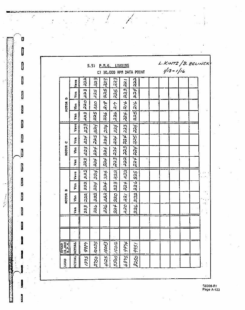
PMG Loading
Data show that there is channel independency within the range of loading and speec:. tested, Table 6-2.
Table 6-2 Measured Output Voltage - Loaded PMG Operation
P.M.G. Voltage Output Motors B, C & D Unloaded Speed Predicted Test Motor A Loaded
1666 38 37 Unloaded Quadrant Motors
38 37-31.4 Loaded Quad @ 0 to 15.4 amperes
4333 98 96-107 Unloaded Quadrant Motors
98 96-56 Loaded Quad @ 0 to 27.3 amperes
10,000 225 222 Unloaded Quadrant Motors
225 218-157 loaded Quad @ 0 to 23.3 amperes
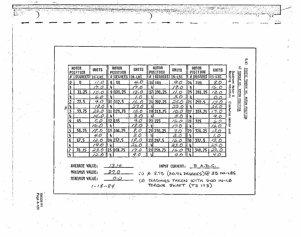
Static Torque vs. Rotor Position
The predicted torque output of 12.6 in-Ib compares to the average measured torque output of 13.14 in-Ib within 4.1%. '
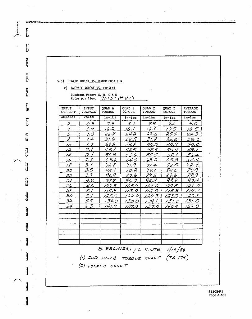
Static Torque Summing
The current-torque curves show a linear relationship for the single channel configuration and a nonlinearity for multiple channel operation. This was traced to deflection of the test fixturing at the higher torque values achieved with multiple channels and not from interaction among the channels. linear summing of torque is expected.
Waveforms and Harmonic Analysis
Motor voltage waveforms were recorded and their harmonic content analyzed. Tests were performed for both loaded and unloaded situations for seveial combinations of speeds. loads" channels and phases. Because of the extens!ve nature of these data. the following index of representative data is provided.
• Voltage Waveforms at No load
a) A comparison of line to neutral and line-to-line voltag~ waveforms as a function of speed can be obtained by reviewing the photographs listed in Table 6-3. These data were obtained from Channel "A".
b) A comparison of the line to neutral voltage waveform for all four channels concurrently can be obtained as a function of speed by reviewing the photographs indicated in Table 6-4. A uniformity is noted among the individual channels.
~A~nA_R1
.'
1 . .)
.:.' ·.···1
..
'J
~-. ~.
..... ~ ..
J
....... ··1 ..
-... , .~.
I I I
't' ./
Table 6-3 Voltage Waveforms at No Load r.~otor Channel "A" Phases A, 8, C
L-N L-L LOAD PHOTO PHOTO (Amps) L-N NUMBER L-L NUMBER
. .
1) 1666 RPM DATA POINT
0 A S.4-A-l A-B S.4-D-l B -2 B-C -2 C -3 C-A -3
2) 4333 RPM DATA POINT
0 A S.4-B-l A-B S.4-E-l B -2 B-C -2 C -3 C-A ·3
3) 10,000 RPM DATA POINT
0 A S.4-C-l A-B S.4-F-l B· -2 B-C -2 C -3 C-A -3
Motor Connections: Line to Neutral (L-N) & Line to Line (L-L)
Table 6-4 Voltage Waveforms at No Load Motor Channels A. 8, C, 0
QUADRANTS (L-N)
LOAD MOTOR MOTOR A MOTOR B MOTOR C MOTOR'D' (Amps) CONNECTION PHOTO PHOTO PHOTO PHOTO
1) 1666 RPM DATA POINT·
° A-N S.4-A-l S.4-A-4 S.4-A-7 S.4-A-8 B-N -2 -S CoN -3 -6
2) 4333 RPM DATA POINT
° A-N S.4-B-l 5.4-B-4 5.4-B-7 5.4-B-8 B-N -2 -S CoN -3 -6
3) 10,000 RPM DATA POINT
a A-N 5.4-C-l 5.4-C-4 5.4-C-7 S.4-C-S B-N -2 -S CoN -3 -6
SB308·R1 P~no &;.'l.
'. .. ..... . , ' ":"
; .. .,. .") - ; ., ~,; !
>;("" .. '-;;' ." .,
'o'.j.
\,'
• Voltage Waveforms at Load
a) An indication of the effect of load on waveform can be obtained by examining the photos listed in Tables 6-5 and 6-6. Data in Table 6-5 are grouped as a function of speed. Data in Tab!.:: 6-6 are grouped as a function of load clJrrent. All data were obtained from a loaded channel "A" with the remaining channels open circuited (unloaded).
b) The effect on the waveform of a loaded channel on an unloaded channel can be obtained by reviewing the data listed in Table 6-7.
• Harmonic Analysis at No Load
a) The harmonic content of the line to neutral and line-to-line waveforms of an unloaded ch:'nnel can be obtained by reviewing the graphs listed in Table 6-8.
• Harmonic Analysis at Load
a) The harmonic content of line to neutral and line-to-line waveforms for loaded channels can be obtained by reviewing the graphs listed in Tables 6-9 and 6-10. Table 6-9 presents the data as a function of speed. Table 6-10 presents the data by motor connection.
Table 6-5 Voltage Waveforms at Load ... Motor Channel A
L-N L-L PHOTO PHOTO LOAD
L-N . NUMBER L-L NUMBER (Amps)
1) ·1666 RPM DATA POINT
A 5.5-A-20 A-B 5.5-A-21 6.1
2) 4333 RPM DATA POINT
A S.S-B-6 A-B 5.5-B-7 14.6 -2 -3 17.8
3) 10,000 RPM DATA POINT
A· 5.S-C-2 A-B 5.S-C-3 10.2 -4 -5 18.1
MOTOR CONNECTIONS: LINE TO NEUTRAL (L-N) & LINE TO LINE (L-L)
S8308·R1 " ___ n ..
! i
/ ! I .-
Table 6-6 Voltage Waveforms at Load Motor Channel A
LOAD SPEED MOTOR PHOTO (Amps) (R.P.M.) CONNECTIONS NUMBER
Table 6-7 Voltage Waveforms Unloaded vs. Loaded Motor Channels A 8. B
1) 4333 RPM DATA POINT
QUADRANT LOAD PHOTO PHOTO MOTOR (Amps) L-N NUMBER L-L NUMBER
A 17.8 A 5.5-B-2 A-B 5.5-B-3
B 0 -4 -5 MOTOR CONNECTIONS: LINE TO NEUTRAL (L-N) & LINE TO LINE (L-L)
Table 6-8 Harmonic Analysis at No Load
A) 1666 RPM DATA POINT
LOAD HA GRAPH (Amps) CONSTANT VARIABLE NUMBER
0 A-N Y 5.4-A-1 N -9
0 N A-N 5.4-A-9 A-B -10
MOTOR CONNECTIONS: LINE TO NEUTRAL (A-N) & LINE TO LINE (A-B)
Y = HARMONIC ANALYZER GROUNDED
N = HARMONIC ANALYZER UNGROUNDED
S830B·R1 Page 6·5
,-'
... '.
0., '
.. .. -'ic .;" '. ""
. ~ - .
,.
····,0 •• ,!'
~ :. ~
. , '. j ."
! i ;-
I
i I
!I , ;
,I I / j, " / i I, I
i/. 1 I , -.'. /
Table 6-9 Harmonic Analysis at Load
LOAD H.A. GRAPH CONSTANT VARIA8LE (Amps) NUM8ER
.1 ) 1666 .RPM DATA POINT
A-N N 6.13 S.S-A-1 Y 9.3 -3 Y 14.1 -5
A-8 N 6.13 5.5-A-2 Y 9.3 -4 Y 14.1 -6
2) 4333 RPM DATA POINT
A-N N 14.6 5.5-8-1 Y 14.4 -3
A-8 N 14.6 5.5-8-2 Y 14.4 -4
N A-N 14.6 5.5-8-1 A-8 14.6 -2
Y A-N 14.4 5.5-8-3 A-8 14.4 -4
3) 10,000 RPM DATA POINT
N A-N 10.2 5.5-C-1 A-8 10.2 -2
MOTOR CONNECTIONS: LINE TO NEUTRAL (A-N) & LINE TO LINE (A-8)
Y = HARMONIC ANALYZER GROUNDED
N = HARMONIC ANALYZER UNGROUNDED
• S8308·R1 Page 6·6
, I
I.
/ I
:,'
Table 6-10 Harmonic Analysis at LOBr]
(R.P.M.) CONSTANT VARIA8LE
1) LINE TO NEUTRAL (A-N)
N 1666 4333 10K
2) LINE TO LINE (A-8)
N 1666 4333 10K
3) LINE TO NEUTRAL (A-N)
Y 1666 1666 4333
4) LINE TO LINE (A-8)
Y 1666 1666 4333
LOAD (Amps)
6.1 14.6 10.2
0.1 14.6 10.2
9.3 14.1 14.4
9.3 14.1 14.4
Y = HARMONIC ANALYZER GROUNDED
J
H.A. GRAPH NUM8ER
5.5-A-l 5.5-8-1 5.5-C-l
5.5-A-2 5.5-8-2 5.5-C-2
5.5-A-3 5.5-A-5 5.5-8-3
5.5-A-4 5.5-A-6 5.5-8-4
N = HARMONIC ANALYZER UNGROUNDED
6.3 MOTOR/CONTROLLER OPERATION
...
Modifications were made to a Sundstrand controller to allow it to drive a single channel. With the controller driving quadrant "A", no-load speeds up to 5,000 rpm were obtained with smooth acceleration and deceleration. Inability to drive the motor at speeds greater than 5,000 rpm was due to the controller. At this point testing was concluded.
S8308-R1 Page 6-7
pt(""} .. ,-i
I '1' .• ... , /
/
6.4 WEIGHT SUMMARY AND DISTRIBUTION
WEIGHT SUMMARY
MOTOR ASSEMBLY (EP2758-10)
a) Stator Inseparable Assembly (EP2758-94)
b) Rotor Balance Assembly (EP2758-210)
c) Other Motor Parts
ACTUAL WEIGHT
12.425 Lbs.
9.329 Lbs.
11.56 Lbs. d) Motor Assembly
(EP2758-10) TOTAL 33.31 Lbs.
WEIGHT DISTRIBUTION
Las LBS LBS NOTE PREDICTED ACTUAL DIFFERENTIAL
A) STATOR INSEPARABLE ASSEMBLY (EP2758-94)
1) Iron
2) Copper
3) Insulation, Tape Leadwire, Sleeving
NOTES:
TOTAL
(1)
(2) (2)
6.853
4.337
11.190
(1) Stator coil form size had to be enlarged to allow for nesting and overlap clearance of coil end turns.
(2) These parts were not weight predicted.
LBS NOTE . PREDICTED
B) ROTOR BALANCE ASSEMBLY (EP2758-211)
1) SEPARABLE WEIGHTS
a) Magnets 1.968 b) Containment feature (3) .182 c) End plates (4) .165
SUB-TOTAL 2.315
7.020
5.230
.175
12.425
LBS ACTUAL
2.301 .099 .335
2.735
+.167
+.893
+.175 .
+1.235
LBS DIFFERENTIAL
+.333 -.083
. +.170'
+.420
S830a·R1 Page 6·8
, .
i \
2) INSEPARABLE WEIGHTS
a) Poles (5) 1.855 b) Hub (5) .781
SUB-TOTAL 2.636
3) NON-ELECTROMAGNE=TIC WEIGHTS
a) 'Shaft (EP2758-213) (6) 1.406 b) Rotor & Shaft Inseparable (6) 5.188
Assembly (EP2758-211). minus shaft (EP2758-213)
TOTAL LBS. (7) 4.951 9.329
NOTES:
(3) The containment feature was changed from a metallic sleeve to a graphite fiber-epoxy wrap.
(4) End plate material was changed from aluminum to stainless steel to allow for material removal during balancing.
(5) Rotor construction does not allow for individual weighing of rotor poles or the hub of the electromagnetic circuit prior to rotor assembly. .
It has been noted throughout this report that motor development is only one step in implementin a successful, electromagnetic summing. flight actuation system. Indeed. some of the more difficu work. the development of a viable redundancy management scheme. remains. Nevertheless. th completion of this project is considered an essential step toward an operational system.
The work accomplished demonstrates that competitive weight and performance are achievabk without difficult manufacturing methods. In addition. a data base has been developed providin, validation of modeling techniques and the necessary background for preliminary controlle design.
The test simulation of failure effects and the development of the associated predictive models i~ viewed as the next logical step toward a functioning four channel controller and. ultimately. to i
fully redundant demonstration system. The test motor is the tool available for this effort.
------------------------------------------,--------------.------------------I I I I 1
i l I I
•
1.0 r10TOR TESTS
Motor assembly part number EP 2758-10
1.1 WINDING RESISTANCE
1.2
1.3
Record room ambient temperature. After allowing the motor to reach room ambient temperature, measure and record the individual phase resistances of each quadrant motor.
WINDING INDUCTANCE
a) Measure the winding phase inductance of each quadrant motor. Rotate the shaft in incremental steps measuring associated induc~ance. Locate rotor position with the centerline of the "sensor end shaft key\'1ay" as the timing feature. Zero mechanical degrees rotor position occurs when the keY\,Jay centerline is aligned with the stator locking screw center-1 i ne.
b) Repeat readings for line to line winding connections.
DIELECTRIC STRENGTH
a} Motor Winding Test 1) Insulation Resistance Test
Apply sao! 50 VAC, 60 hertz for one minute bet\'Jeen the neutral 1 ead of quadrant moto,- "A" and ground. Record the insulation resistance valu~. Repeat the test for the remaining quadrant motors. Repeat the test bet\'1een the neutral 1 eads of quadrant motors "A" and "B". Record the insulatio'l resistance value. Repeat the test for the remaining quadrant motor combinations.
2) High Potential Test Apply 1275 ~ 25 VAC, 60 hertz for one minute or 1530 ~ 25 VAC 60 hertz for one second bet\'leen the netral lead of quadrant motor "A" and ground. 00 not exceed a I"ate of 500 volts per second \~hen applying this power. Record the leakage current value. Repeat the test for the remaining q~adrant motors. Repeat the test bebJeen the neutra 1 1 eads of quadl'ant motors "A" and "B". Record the leakage current value.
Repeat the test for the remaining quadrant motor combinations. 3) Insulation Resistance Retest
Repeat step.l.3-a-l
............. j t
··.·.·.·1:··::···~ . -
"
. ~.' " , ..
I I I ~
J
a
1.4
1.5
1.6
1.7
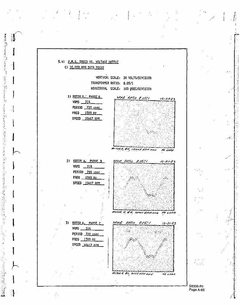
PERHANENT HAGNET GENERATOR (P.H.G.) SPEED VS. VOLTAGE OUTPUT Drive the motor as a P.M.G. at indicated speeds. Measure the phase voltage output of all quadrants, and if possible. the torque input at each speed point. Obtain an oscilloscope voltage trace of all phases of quadrant motors "A" and "B" and phase "A" of the remaining quadrants at each of the motor speeds 1666, 4333 and 10,000 R.P.H.
If time permits';' repeat above test on quadrant motor "A" measuring line to line voltage and obtaining waveforms. If instrumentation is available, perform harmonic analysis on each quadrant during above test.
P.M.G. LOADING Drive the motor as a P.M.G. at indicated speeds while loading quadrant motor "A" to desired values of phase current. Measure quadrant motor "A" watts, the phase voltage of all quadrants, and if poss~ble, the torque input at each speed point. Maintain as near constant motor temperatures as possible for each reading. Obtain oscilloscope voltage traces of the loaded and unloaded quadrant motors at speeds of 1665,4333 and 10,000 R.P.M.
If instrumentation is available, perform harmonic analysis on each quadrant during abo~e test.
STATIC TORQUE VS. ROTOR POSITION
Apply D.C. power between phases "A" and "B" of quadrant motor "A" at one value of D.C. current. Record shaft torque output as a function of incremental rotor position.
Increase cur'rent 'in incremental steps at one rotor position. Record shaft torque, inpl'c current and voltage. Maintain as near constant motor temperatures as possible for each reading. Repeat for quadrant motors B, C & D.
STATIC TORQUE SUt"MING
Apply D.C. power bet\oJee,1 phases "A" and "B" of quadrant motors "A" and "B" connected in series. Increase current in incremental steps at one rotor position. Record shaft torque, input current and voltage. Maintain as near constant mot0r temperatures as possible for each reading.
Repeat the test for phases "A" and "B" connected in ser';es for quadrant motors A, Band C •
Repeat the test for phases "A" and "B" connected in series for quadrant motors A, B, C and D.
REF: PHASE RESISTANCE = .0872 TO .0936 ohms @ 770F
PHASE A TO PHASE B TO PHASE C RESISTANCE NEUTRAL NEUTRAL TO NEUTRAL
UNITS OHMS OHMS OHMS
MOTOR A .oq! ,0'1 Z. ,oqz, ' .
~1OTOR B .Dq I ,0'10 .Osq
MOTOR C . '
.0'13 .09 Z. ,oqz.
MOTOR D ,0'1 I .Oqz. .0'8 '1
INC.Lu'06 ,002.~-
OF M p."\ ( N ~ Co to IJ E- c.T o~
-rlLl\
... : '", >-" ' . "
- ........ ~ ,
- ':"
-'- .. ' .
.. I •
1 •• (·.· :
. .' .~ .. :: ..... , . ... ,;,.. -. --.
WINDING INDUCTANCE DAT14
, \ , ,
\
I
J
I J
t J
t
J
I I
I }
, ,j'
i ,.J
., , , _._ .. -----. "
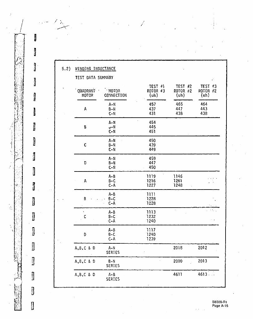
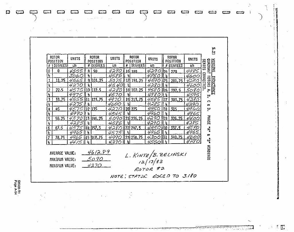
5.2) WINDING INDUCTANCE
TEST SUMMARY
1) ROTOR #3 (10-26-83)
Inductance values were obtained using the first available rotor. Rotor #3 had some containment epoxy-wrap deficiencies, however it allowed obtaining prelimlnary inductance mapping values.
2) ROTOR H2 (11-17-83)
Inductance values were obtained using the final configuration rotor balance assembly. Additional stator \·linding combination tests were established to providp further data comparisons. These are series connected line to neutral and line to line lead combinations for all quadrant motors.
3) ROTOR #2 (12-9-83 to 12-13-83)
A runout of approximately .003 inches was observed on the lead end of the stator core 1.0. The core was then ground to 3.180 inches concentric to the stator housing pilot diameter. Upon completion, the inductance test was rerun in portion for comparison purposes.
5B30B·Rt
J
.;z.
~ .'
I
I j
I I I B
D
n jj
n
j
B
n
9
fi g
~
;' , /.
5.2) WINDING INDUCTANCE
TEST DATA SUMHARY
QUADRANT' . 'MOTOR HOTOR CONNECTION
A-N A B-N
C-N
A-N B u-N
C-N
A-N C B-N
C-N
A-N o B-ti
C-N
A-B A B-C
C-A
A-B B B-C
C
o
A,B,C & 0
A,B,C & 0
A,B,C & D
C-A
A-B B-C
"C-A
A-B B-C C-A
A-N SERIES
B-N SERIES
A-B SER!ES
i
TEST #1 ROTOR #3 (uh)
457 437 431
454 445 451
450 439 449
459 447 450
1119 1216 1227
1111 1228 1228
1113 1232 1240
1117 1240 1239
TEST #2 ROTOR #2
(uh)
465 447 438
1146 1261 1248
2018
2000
4611
i
TEST #3 ROTOR #2 (uh)
464 443 438
2012
2013
4613 .
S8308·Rl Page A·15
"'Ow !>lex> ;Ow (~ 0 ,.'P .:..:0 m ....
ROTOR UNITS POS ITION # DEGREES uh 0 0 .J.5;J. J:; lff3 1 11.25 .tJ5;t Is 4;;'0
2 22.5 ~5;J.
·Is ~P3 3 33 is t/~/ l.I H;Jd
4 45 Jj;J?
J..; L/~7
5 56.25 i.J56 Is ~-::>
6 67.5 454-Is 4;'?5
,7 78.75 ~5~.~ J..; t,L'~'I_
AVERAGE VALUE: MXIHUM VALUE: MINIMUM VALUE:
ROTOR UNITS POSITION # DEGREES uh 8 90 It c.~ I./.
P~~W~ON UNITS UNITS UNITS UtIlTS ~ g 1_ # DEGP.EES ;; e; a o 0 ~~~ ~~~~~:~~+~~--~~~~~~--~~~~~~--~~~n~
~ g~-:;::02
1 ~dg ~ a~~ 2 • ~:z [~ 3 I 33.75 I L/555 1111 1123.75 I #70 11191213.75 I1-Sf51127 1 303.75 I lj.;J,fo
lIs-I I ¢~ 75-'1 Ij L___-' ¥bOO IL~I L~.JR5" Is I __ I L/~ 90 4 I 45 I ¢575111ZU35 __ L4d2QJllOl225_LM50JI28 L3li_L!Mrc.o ~ I 1 £990 Ills 1 1 L/-5-t/-S II lJl_._ I t/-'lfoO IL~ 1~ __ L49'65 5 I 56.25 14157011131146.25 I 509011211236125-'~'tQJI19l3~51 #00 ~ I I 4;<.f'5I1lj I I '-I-5~611 lJl ____ ['l~9QIL~T I ¥:JR5
~ I 67.5 1~Ps"lfi~ ~5j.5 1~~II=~12g7.5 I $~~-' 337.5 It$t~ 71 78. 75 1.-1%6 Ui5Ju:~,.!.!. .• ~75:-t-~~~~~~~~f¥-:L+-£!~~~~ ~ __#.-IsIITC
Quadrant motors A,B,C & D neutral leads are designated below as A,B,C & D.
TEST M!X> I POINl'S o~s
A-GND :301<
B-GND ~3.~1<
C-GND ~tf K
D-GND 75~
n::sr romrs ma
A-GND I,as
B-GND I.a C-GND
J. d.5
D-GND 1,~5
TEST MEG PC~":'S aMS
A-GND 10K
B-GND ~5K
-C-GND ;5~
D-GND IDOK I
1) INSULATION RESISTANCE TEST
TEST rID:; l~ tl$ FOINI'S (US • roTh"rs OHl~S
A - B b~ 1< 11
B - C 30K
A - C 351( I B - 0 taSK
A - 0 3SK. r --- ------ --- I --- ---
2) HIGH POTENTIAL TEST 'l'ES'I' ma I 'reST ma POnns FOnns
A - B O.IV B - c D./~
A - C C.1CZ B - 0 D./S
A ~ 0 0,11 --- ------ --- --- ---
3) INSULATION ~ESISTANCE RETEST
n:sT tID; TEST K::G FOINIS Ol!-S FOINl'S at'S
A - B 1~5K. 1 B - C 351'
A - C 100(<- B - 0 I'1K
A - 0 '10\<- --- ------ --- --- ---
TEST PODn'S
F I ---
------
'l!'Sl' POINTS
C - 0
---------
TEST POnns
C - 0
---------
~ C!~
33K
---
------
ma
0.1/
---------
t~
OI-MS
aOK
---------
SB30B·A1 Page A·55
f·
i , I: ~. " "
(\
" "I
, , I j , 1
r
j 1 (-~
I I I I , 9
o 0("
o
P.M.G. SPEED VS. VOLTAG OUTPUT DATA
..... !" .. :
"
',I i j
1
t',' -, "
D
B ~
ill
0 B B
~
0 ~
u ~
~
9 ,.
n ~
n ~':
~
(~
(~
0.
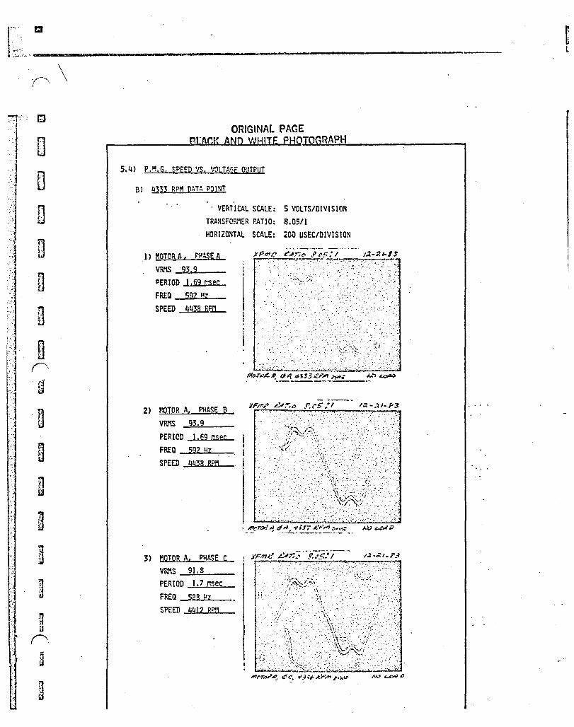
5.4) P.M.G. SPEED VS. VOLTAGE OUTPUT
TEST SUMMARY
1) ROTOR #3 (11-14-83) P.M.G. voltage vQ1ues were ~btained using the first available rotor. Rotor #3 had snme containment epoxy-wrap deficiencies, however it allowed obtai '1ing preliminary speed vs. voltage values.
2) ROTOR #2 (12-7-83)
A runout of approximately .003 inches was observed on the lead end of tile stator core 1. D. The core was then ground to 3.180 inches concentric to the stator housing pilot diameter. Upon completion, the generated voltage test was run using the final configuration rotor' balance assembly.
All photographs and harmonic analysis data oertain to this rotor configuration only.
·'
SB30B·R1 Page A·56
/
.I.
:iz. ;
........... '~ .. ~
" ... j
' .. ~ ,
~.
i' , ,
! !. , i t 1 t , f.
t , , t , I
"-
5.4) P.M.G. SPEED VS. VOLTAGE OUTPUT
! PHOTOGRAPH VS. HAR~\oNIC ANALYSIS CROSS REFERENCE TABLE ,~
PHOTO SPEW LOAD QUADRANT MOTOR HARMONIC ANALYSIS '1
NU~1BER (R.P.t1. ) (AHPS) r~OTOR CONNECTION GRAPH NUMBER
5.4-A-l 1667 0 A A-N 5.4-A-l, -9 -2 1640 1 B-N -2 -3 1661 C-N -3 -4 1667 B A-N -4 -5 1655 t B-N -5 -6 1645 C-N -6
! -7 1668 C A-N -7 -8 1671 0 A-N -8
1 5.4-B-l 4333 0 A A-N 5.4-B-l -2 4337 ! B-N ! -3 433G C-N -j
5.4-B-4 4336 B A-N 5.4-8-2
I L
-5 4347 ! B-N I' -6 4329 C-N ... 1 -7 4346 C A-N 5.4-8-3 ,I
. 100 ' I .. FUN~NlENTAl I • • .• ~ •.• : T .. :. . I I
It:·; . I. I I' !. I ...: .. Ii r ~rd. harmont~ • l I I : : :'. (a 8.2% ' . :, '. 1"'-' t· ......... ,._-.. .... ':', I····: ...... I .... J. .. I .... ,J ........... . : . . I .. . .. . ',! 5.4) P.M.G. SPEED VS. VOLTAGE OUTPUT
" . . ' I : 10 1--'''; 1._ . - ._. -._. j .__ .. __ ,j d 5th. bl~ c: .; I: :' :'7':'"; :.::.: A) 16.66 RPM DATA POINT
. ... ~.' .. :! .:' ... ~ ;", .; @ lOS .. ... .- I. 8) HARmNIC ANALYSIS ........ , .. - I ; ... - .. - ... : .:.:i,':':_ .: :::.~ ::.:: .~._ Percent Fundamenul vs. Frequency
'1'--" _. .. •. !.... . ... -. - .. -- t , 1660 RPH, Hotor 0, Phase A
:~~"4 H J ~IIH-T 1~1i 11+> K !Il III +HHHH Ijll lwttth iiil HIl q"ltH!llf!f, It If I . '. ' "11 '!I; I I! !,!<I!',' . I! ~i!1 II ,Ill' l"'l I .. i'j ,'1.: : ,'" ill. il! 1:1' it' I 11,1' :... .o., l r., : ~ +++:; ..: ~~ Po J.J .• ,L! ~h! ._l~ ... ~. H:~ i'n p~~ 'H ~,.-f' t, H t
.1 mi'fi~ ~~,;IffK ;"'I~~'~~ "; .': ;:U!E ~@jj~I~:'" ~~~Ji~ ~:ili~l!lJ~"j~:~I!;OU'1 : ::::~ B I un f/l "II '". ill I "t!! ,j 'III ,j, II m!l llill'!W IHH III H 1ii41rt4 ~~ In~ ~I!! hli " l!I!m' , ri:~:! :"~t~ ~ ~ i!,~ ,,:: ~.~.~ tr ~t:'I~Wl1181!+Hff1ffiqH ~$~~t~lm~ I,n I I WJ
L. k'1/VTZ tR/~/.?~ (/) 500 11\/-1-13 70,eQUe SH/),cr (rs/'7.3)
(~) LOCK.E.D SA'.t}Pi
S8308·Rl Page A·152
· .. •. ".01
~""< ['; ooH /!J
( u ,,--. APPEN03X B
CONTROL STRATEGY
t, .~ ·~i :. :.··~.:i .0'
I} B r )
:~
L:: t·,~
~ i O
,
r~ r~ t= ji
.o.~ \ ft ,\
. ,
r~~: Eoo-o f" :~ o\-, rev r'i
\
0 r4.~
t~ "
~ '.,
I F
\
~ . ,0. f;, ; f
i~ .~:
r F
~ t· ~ ...... ! .. ,:, (~
.'l
]
1
B D
H g
U
u
~ rn
n
Optimization of Brushless DC Motor Design
By Jayant G. Vaidya, Sr. Research Engineer Sundstrand Corporation, Advanced Technology Operations Rockford, IL 61101
Introduction
Brushless dc motors are generally required to operate under widely varying conditions of load. These varying conditions include: changes in torque, changes in speed, and resulting changes in power output. On the other hand there are changes of input voltage and commutation angle that are optional and can be selected to suit the performance capabilities of the brushless dc motor. The back e.m.f. and the winding inductance per phase of a multiphase brush less dc motor are the two design parameters that must be selected to obtain an optimum design. It is the purpose of this article to present . techniques for optimizing the performance of brushless dc motors by selecting the design parameters and the optional operating points for input voltage and commutation angle for specific load characteristics.
A simplified model representing one phase of a multi-phase, permanet magnet field brushless dc motor is employed. It is proposed that such a model is. an extremely convenient tool for evaluating performance under a variety of operating conditions. It is indicated how this simplified model can be applied to optimization of the brushless dc motor design. It is then shown how the technique of optimization can be applied to different types of designs for specific load characteristics such as constant torque, constant speed, constant power, and combinations thereof.
The Simplified Model of Brushless DC Motor
Consider one phase of a permanent magnet field brushless dc motor having an n-phase winding. If the winding resistance is neglected, this phase can be represented schematically as shown in Figure 1. The applied voltage is V volts r.m.s. per phase and the back e.m.f. is E volts r.m.s. per phase. Let us assume that both V and E art sinusoidal. The winding inductance is .. L henry. Let us assume that there is no magnetic saturation in the armature· iron so that the value of L remains constant regardless of changes in cur,·ent. Since most of the machines to which this analysis is applied are likely to use permanent magnets with the relative permeability close to one· (such as ceramic or samarium cobalt magnets), it is safe to assume that the winding inductance L remains practically constant regardless of the angular positionS830~Rl of the field with respect ~.o the armature winding. Page 8-1
i-,; "
L
L L.· [_.
r , r r· I ~ ,.
r 1: vi , I ~ .-. ~ ..
I J
~ I h
;:
L
"-' ;
, .:.' I
I I
. ,
Defining the r.m.S. value of the current in the phase under consideration as I amperes.
i = ij E 2'ITfL
where i. ii. E are phasor quantities and f equil", ... e frequ~ncy in Hertz. Defining the commutation angle as 0 radians and the power factor angle as
(1)
¢ radians. the phasol diagrams with all the quantities can be drawn as sho~n in Figure 2. The power input to the motor is given by
P = n VI coslj> (2)
This is also the power output if all the losses such as iron losses and windage and friction losses are neglected for our simplified model. By examination of the phasor diagram.
I = Esino 2'ITfL (coslj>
Combining equations (2) and (3) above.
P = nVEsino 2'ITfL
(3)
(4)
This is the well-known power equation for the cylindrical rotor. synchronous machines.
Using the Simplified Model for Design Optimization
Certain general comments can be made regarding the brushless dc h.Jtor on the basis of equations (2). (3). and (4). These are as follows:
a) The power is proportional to the back e.m.f. E. This can be increased at the cost of increased weight of the permanent magnet field as well ~s the armature.
b) The power is inversely proportional to the inductance L. Thus if.· the number of turns in the armature ;s increased to increase the back Lt·'.F •• the ioductance increases in proportion to the square of the number of turns. This will in fact reduce the power.
S830a·R1 Page B·2
L . "
n B B ~
rn
~
B rn
rn
'" m
m
B n 9 ~
~
w ."
,--.. 8 g
c) To keep the motor current as low as possible, the power factor, cos~ must be kept close to 1. HcrNever any attempt to increase cos¢ requires changes in the back e.m.f. E and the commutation angle o.
To clarify these points, let us consider the case of a fixed pm'ler, constant speed brushless dc motor, operating from a fixed input voltage. Although such a simple requirement may not occur in practical situations. it will help illustrate the optimization procedure. In order to keep the armature current to a minimum, let us assume that the pm'ler factor is restricted to 1. Then applying equation (4), the power
p a: Esino L
Once a certain configuration of the motor is determined the value of E can be increased by increasing the stack length of the motor. However. the inductance L also increases with the stack length. Then
P a: sino
However, from the phasor diagram of Figure 2.
E coso = V, for COS9 = 1
or
If we define a variable e = ~/V,
sino =-Vl - 1/e2
then
Now the weight of the motor is a function of the back e.m.f. and we can express,
(5)
(6)
where x is va~iable dependent on the total weight increase caused by the increase of back e.m.f. E. Then we can define the power per unit weigh~ a~
(7)
S830B·R1 Pago B·3
•
t , I
I [ I ~
r.
0
i :
r/"..,
, i I I I I I J Il
~.
a n n D
a4g4a:53#t't#*
This equation is plotted in Figure 3 for several values,of x to illustrate how an optimum power to weight ratio can be obtained. From the curve for any specific value of x, the optimum value of e and the optimum value of the back e.m.f. E can be selected where the ratio P/W reaches its peak. Any further increase in the back e.m.f. E will in fact result in a less than optimum design. Similar curves can be plotted for power factors other than 1.
Let us consider another case where the value of E is fixed as a pe~ centa£eof the applied voltage V, and the power factor must be otimized. Two independent situations arise in this case: One \'Ihere E is less than V, and the other where E is greater than V. Fi gure 4 sho\,/s the phasor di agram for the situation where E is less than V. Here the maximum value of the power factor cos~ is attained when the power factor angle ¢ is smallest. This occurs when the phasor (\i-E) is tangential to the locus of E as shown in Fi9ure 4. At this point the power factor angle and the commutation angle are equal and
cos¢ = cosc = E/V
And the pm'ler equation (4) for the optimum power factor becomes,
P = nEVV2-E2 271fL
(a-a)
(9-a)
In the second situation where E is greater than V, the maximum value of the power factor that can be attained is 1 as sho\'In in the phasor di agram. The commutation angle c is given by
coso = VIE
And the pO\.,rer equa ti on (4) for the power factor of 1, becomes,
p = nVih2_V 2
271fL
Ilsinn equations (9-a) and (9-b), optimum values of the winding inductance
. (a-b)
(9-b)
per phase. L can be determi ned fl)r gi ven app 1 i ed voltage V· and back e. m. f. Lihe optimum value of commutation angle c' can be determined using equations (8-a) and (8-b).
S8308·R1 Page 8·4
r ". n " .
r: H
8 ,
U
il I.'
D
B ~
\ g ,r"'\. U ;
n tl
D (~
H n n H
D f,,\
D
H ~ ..
Constant Torgue Operation
The procedure for optimization of the power factor as discussed abdve can be extended to the constant torque load characteristics shown in Figure 6. First the design parameters may be optimized at the highest operating speed of N? R.P.M. where maximum power occurs. At this point the input voltage should be held at its maximum value V. As the operating speed of the motor is reduced, the back e.m.f. E as well as the reactance 2wfL reduce in proportion to the speed. The power factor can be held constant at its optimum value if the applied voltage V is reduced in proportion to the speed. The commutation angle c is also held at its original value throughout the operating range. The power as in equation (4) falls in proportion to the reduction of the applied voltage V as the speed is reduced.
Two cases, one with the back e.m.f. E less than the applied voltage V, and the other with the back e.m.f. greater than the applied voltage V are shown in Figures 7 and 8. Equations (8-a) and (9-a) and (8-b) and (9-b) app 1y to the b/o cases at the peak speed of N2 R. P. M. At any lower speed N, the power is re~uced by the factor N/N2 as required by the load.
Constant Speed Operation
The constant speed characteristic is shown in Figure 10. One approach ~ou1d be to optimize the power factor at the peak torque load keeping the back e.m.f. E below the value of the applied voltage V as shm·m in Figure 4. Then as the torque is reduced from its peak value, the applied voltage ~~n be reduced, holding the c~~mutation angle constant so that the power factor increases until it reaches the value of 1. This is shown by means of a phasor diagl~m in Figure 1). At the peak torque point, the relationships of equations (8-a) and (9-a) are valid for the optimum power factor. The' minimum torque level that can be then reached for the power factor of lis' then gi ven the fo 11 owi ng equa ti on, . ,
where,
T1 = Torque at power factor of
T2 = Peak torque.
(10)
Any further reduction in the torque can be obtained by reducing the commutation angle and simultaneously increasing the applied voltage to main
S8308·R1 Page 8·5
•
, .
~
.. ~
;.
\.1
r' .. , ,~
i t"
f I, l ! V' iI-'-
t: ./ I
I "
J
(: .' . . ,. \ . I r
~
0'.
I r
J f. ! ~ '.
, ! .. i ;.
~ .
,~ . '.
,. t· f
I
k £..lJ. ...
I
J
I I I D if
I ! ~ g
il n n
tain the power facotr at 1. ihis procedure will allow unlimited reduction in the torque right down to zero.
Constant PmoJer Operation
Consider the load characteristics shown in Figure 11. where the power requirement remains constant over the speed range from N, r.p.m. to N, r.p.m. In this case to get the optimum design. it is best to restric~ the current at the maximum and minimum speeds to a certain value. consistent with highest possible power factor. Here once again the ratio of E to 2nfL remains constant over the speed range. and if we keep the applied voltage constant. then the power
pex sino
Since the power is constant throughout the operating range. the commutation angle 0 should rernain constant. Now let us set the back e.m.f. E at speed N1 such that at the required power level. the optimum conditions ~f Figure 4 and equations (8-a) and (9-a) are attained. Then at the highest speed of N2 '
(11)
(12)
Thi's will result in a shift in the power factor angle from <P1 lagging to 92 leading. In order to keep the currents for the two speeds equal. ~1 and ¢2 must be equal as can be readily seen by applying equation (2). Phasor dIagram for these t\oJO speed condi ti ons is shown in Fi gure 12. Then from. the phasor diagram. for the optimum condition of ¢1 = ¢2 = ¢.
(l3)
Combining equations (12) and (13)
. (14)
From equation (14) it can be seen that the optimum power factor for constant pm'ler operation at the extreme speeds of N1 R.P.M. and N2 R.P.M. is given by
co,~ = co, [i co,-1 :~ J '. '. (1S)
S8308·R1 Page 8·6
~
9 a u g
B ('~
~
As the speed range is widened, the power factor at the extreme speeds gets lower. The pOl'/er factor at all intermediate speeds is always above the value reached at the extreme speed conditions.
If it is desired to improve the power factor beyond the value obtained using equation (15), it \'Ii 11 be necessary to arrange switching of winding connections from star to delta or from parallel to series at a predetermined speed between the upper and 10'ller speed limits.
Combinations of Different Load Characteristics
In practical design applications combinations of two or more types of speed torque characteristic curves may occur. Figure 13 illustrates one such case. Yere the entire load characteristic can be split into two parts: one constant torque operation from the speed N R.P.M. to the speed N R.P.M. and another constant power operation from the ~peed N? R.P.M. to N, R~p.r~. Each part can be treated individually as already discassed. Thus ouring the constant power operation, the pOl'ler factor may be optimized at the extreme speeds of N, R.P.r~. and N3 R.p.r~. The applied voltage V and the commutation angle 0 are held constant throughout this speed range. On the other hand, during the constant torque operation, the applied voltage may be reduced as the speed is reduced and the commutation angle is held constant. Similar approach of dealing with the load characteristics in parts may be taken . where other combinations of speed torque curves occur.
Conclusion
An approach to the optimization of the design parameters for permanent magnet field brushless dc motors is presented in this article. Certain . assumptions have been made so that specific goals for the design parameters such as the back e.m.f., the winding inductance and the commutation angle can be established for any specific speed torque curve. Once this is done, the basic electromagnetic design of the brush1ess dc motor can be established. After this a detailed analysis of the design at specific load points of . interest will require inclusion of other parameters ·such as winding resistance, saturation of iron, variation of inductance, harmonics in applied voltage and back e.m.f., and various losses which were neglected in the model employed in this article.
sa3Da·R1 Page B·7
. r;.-;m A , '
I i I , • , ~,
I '
I I ! .. I I I ! f I I , • I ! f
! r r
.,
;-...... \
[ ~ I I L:
-.....-
J
I I I I
-I
I J
~
~
B £l
t P/w
.6
.• 4
.2
1.0 1.2 1.4
E = e 0+-
V
--.-~ .. .-.- -.. ~--- .. ~
x = .5
--~X=.75
x = 1
. x· = 1.25
1.6 1.8 2.0
Figure 3: Pm'ler to Height Ratio as a Function of Back E.f1.F. to Applied Voltage RL~iot with Power Factor~ cos~ = 1.
S8308-R1
~J - U
D ill ~
ill 9 rn g
("ill ~-- ; ill
B ~ g n jj
g
B ~'\~
~ """ : ....
L
E
I
/ /
v
Figure 1 Schematic Showing One Phase
v
Figure 2 Phasor Diagram
(V-E)= I(2TlfL)
I.l (V-E)
S8308-R1 Page B-9
/'
./
LOCUS /' OF E .,.. --
/ /
/
I
Figure 4 Optimum Power Factor for E <V
cp = 0 I V
I I
I LOCUS / OF E
/
Figure.5 Optimum Power Factor for E >V
S8308-R1 Page 8-10
·1
./
,.. ,:.:', a r-'--..
~
Q
[J
B
~
D
ill
. ~ ill
ill
t· . • ••• 0
TORQUE
~----
"
E
Figure 8 : Constant Torque Operation,E >V
, ;.: "
PEAK .--___ --. / POHER
: POINT
v
I J
I I I I , I
Figure 7 : Constant Torque Operation, E <V
<I> = 0 I
-
' ..
v
E
S8308·R1 "" Page B-11
\ ~
\
t
Torque
1.-
v" /
T -----------2
" i
tL,o a o g g
U rl B o
r-)1 ill
. Ii ,Ii D . '; u /
./ I
I
n U
n U
t
Torque
j
Speed -+
Fig~re 11 Constant Power Operation
Figure 12 Constant Power Operation Phasor Diagram
S8308-R1 Page 8-13
"'-""
J
I
I I I I i 1
t
Torque
Speed -+
Figure 13 Combination of Two Speed Torque Characteristics