1 Materials and Systems Research, Inc. This presentation does not contain any proprietary or confidential information A Reversible Planar Solid Oxide Fuel A Reversible Planar Solid Oxide Fuel - - Fed Fed Electrolysis Cell and Solid Oxide Fuel Cell for Electrolysis Cell and Solid Oxide Fuel Cell for Hydrogen and Electricity Production Operating Hydrogen and Electricity Production Operating on Natural Gas/Biogas on Natural Gas/Biogas Greg Tao, Tad Armstrong and Anil Virkar Materials & Systems Research Inc., Salt Lake City, UT Glendon Benson, Aker Industries, Inc., Oakland, CA Harlan Anderson, University of Missouri-Rolla, Rolla, MO 2005 DOE Hydrogen Program Annual Review May 23, 2005 Project ID#: PD2
Transcript
1Materials and Systems Research, Inc.
This presentation does not contain any proprietary or confidential information
A Reversible Planar Solid Oxide FuelA Reversible Planar Solid Oxide Fuel--Fed Fed Electrolysis Cell and Solid Oxide Fuel Cell for Electrolysis Cell and Solid Oxide Fuel Cell for
Hydrogen and Electricity Production Operating Hydrogen and Electricity Production Operating on Natural Gas/Biogason Natural Gas/Biogas
Greg Tao, Tad Armstrong and Anil VirkarMaterials & Systems Research Inc., Salt Lake City, UT
Glendon Benson, Aker Industries, Inc., Oakland, CA
Harlan Anderson, University of Missouri-Rolla, Rolla, MO
2005 DOE Hydrogen Program Annual ReviewMay 23, 2005 Project ID#: PD2
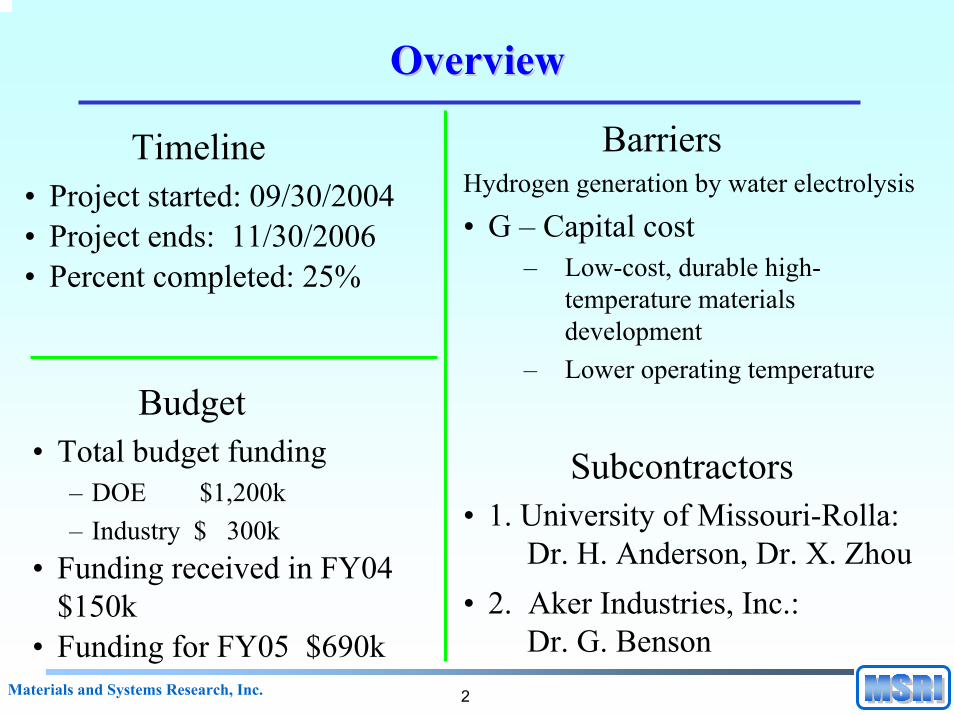
Dr. H. Anderson, Dr. X. Zhou• 2. Aker Industries, Inc.:
Dr. G. Benson
3Materials and Systems Research, Inc.
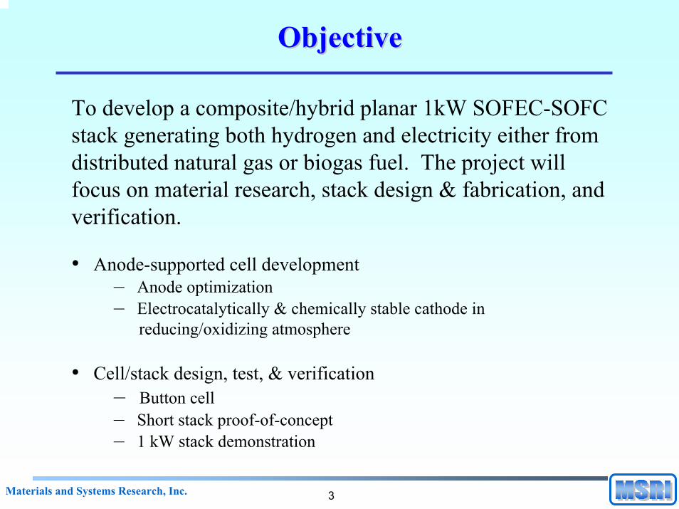
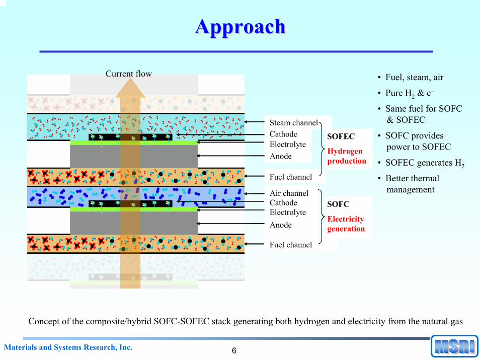
ObjectiveObjective
To develop a composite/hybrid planar 1kW SOFEC-SOFC stack generating both hydrogen and electricity either from distributed natural gas or biogas fuel. The project will focus on material research, stack design & fabrication, and verification.
Anode-supported cell development – anode w/ electrolyte
• Objective:Increase anode porosity and decrease thickness to minimize concentration polarizationDevelop anodes with improved mechanical and thermo-mechanical propertiesFabricate anode-supported cell with defect-free thin electrolyte layer
• Approach: Vary composition and microstructure of NiO + YSZ anodesVary pore-former to adjust porosityImprove quality controlDIR (100%) capability at 700-850 oC
• Issues:Trade-off between strength and porosity/thicknessProperty measurements at high temperatures and in reducing environment
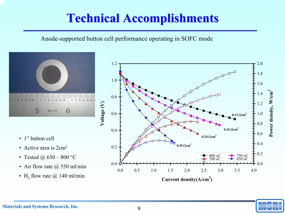
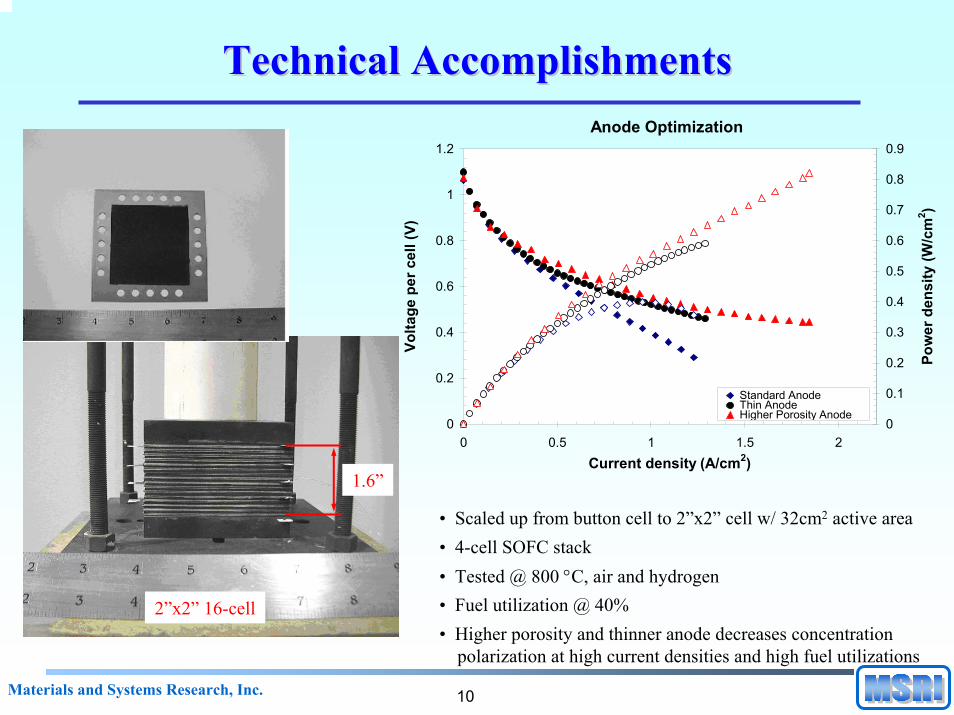
• Scaled up from button cell to 2”x2” cell w/ 32cm2 active area • 4-cell SOFC stack• Tested @ 800 °C, air and hydrogen• Fuel utilization @ 40%• Higher porosity and thinner anode decreases concentration
polarization at high current densities and high fuel utilizations
• Scaled up to 4”x4” 10-cell stack w/ 92cm2 active area
• Tested @ 800oC
• Steam to carbon ratio @ 2:1
• Fuel utilization @ 40%
• Oxidant utilization @ 40%
SOFC Stack Operation with Methane DIR (100%)
0
2
4
6
8
10
12
0 10 20 30 40 50 60 70Stack current (A)
Stac
k vo
ltage
(V)
0
50
100
150
200
250
300
350
Stac
k po
wer
(W)
H2CH4
4”x4” 40-cell 1kW stack
13Materials and Systems Research, Inc.
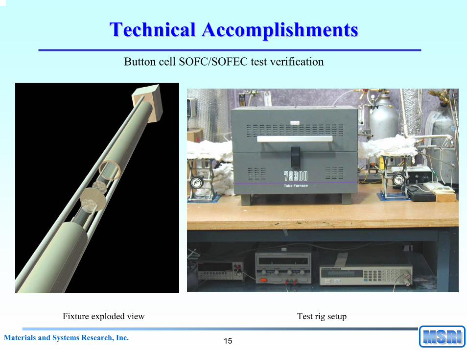
Technical AccomplishmentsTechnical AccomplishmentsCathode development for SOFEC
-24 -22 -20 -18 -16 -14 -12 -10 -8 -6 -4 -2 0 2
10
20
30
40
50
60
La0.70Ca0.30CrO3-δ
log(pO2)
σ (S
/cm
)
0.00
0.05
0.10
0.15
0.20
0.25
700ºC
Ce0.90Gd0.10O1.95
σ (S
/cm
)
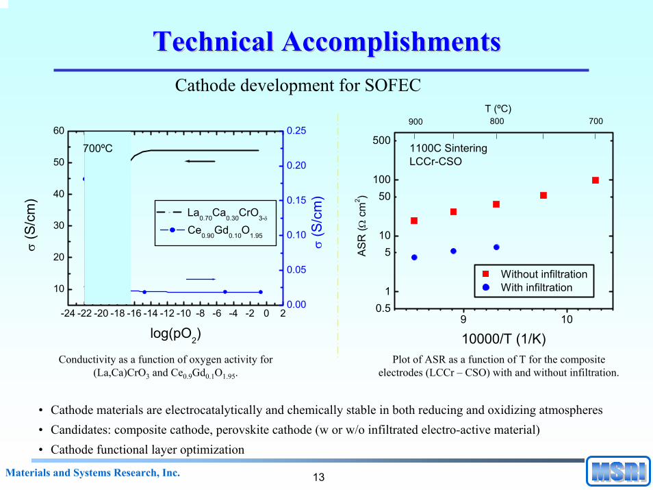
Conductivity as a function of oxygen activity for (La,Ca)CrO3 and Ce0.9Gd0.1O1.95.
9 100.5
1
510
50100
5001100C SinteringLCCr-CSO
T (ºC)700800900
Without infiltration With infiltration
AS
R (Ω
cm
2 )
10000/T (1/K)Plot of ASR as a function of T for the composite
electrodes (LCCr – CSO) with and without infiltration.
• Cathode materials are electrocatalytically and chemically stable in both reducing and oxidizing atmospheres• Candidates: composite cathode, perovskite cathode (w or w/o infiltrated electro-active material)• Cathode functional layer optimization
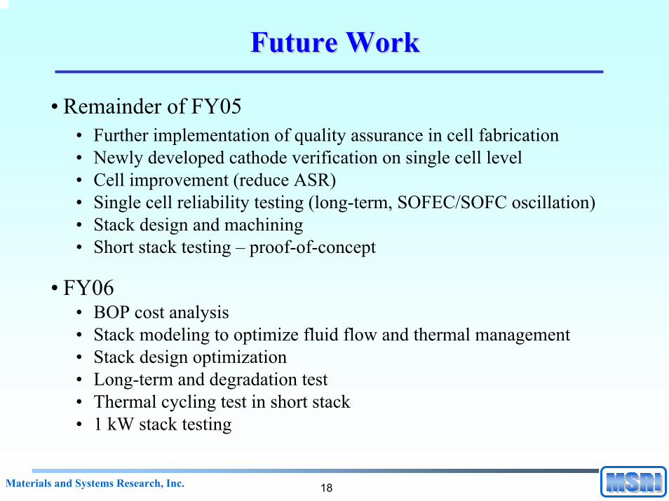
• Remainder of FY05• Further implementation of quality assurance in cell fabrication• Newly developed cathode verification on single cell level• Cell improvement (reduce ASR)• Single cell reliability testing (long-term, SOFEC/SOFC oscillation)• Stack design and machining• Short stack testing – proof-of-concept
• FY06• BOP cost analysis• Stack modeling to optimize fluid flow and thermal management• Stack design optimization• Long-term and degradation test• Thermal cycling test in short stack• 1 kW stack testing
19Materials and Systems Research, Inc.
AcknowledgementAcknowledgement
Department of Energy
• DOE Golden Field Office: David Peterson• DOE EERE: Matthew Kauffman
Pete Devlin
20Materials and Systems Research, Inc.
Hydrogen SafetyHydrogen Safety
• The most significant hydrogen hazard associated with this project is:
• having a leak from the hydrogen storage tanks or from the testing setup that may cause an explosion.
• Our approach to deal with this hazard is:• all of the hydrogen that is on site is stored in qualified pressure
vessels and is located in a secluded area away from ignition sources, oxidants and other chemicals. All of the hydrogen pipelines have been leak tested and are rated for the operating pressures. All testing setups are located under ventilation hoods that are rated at 3000 CFM.