This paper was presented as opening lecture at the Fourteenth Meeting “New Trends in Fatigue and Fracture” (NT2F14) Belgrade, Serbia, 15–18 September, 2014 Guy Pluvinage 1 , Julien Capelle 1 , Mohamed Hadj Méliani 2 A REVIEW OF THE INFLUENCE OF CONSTRAINT ON FRACTURE TOUGHNESS PREGLED UTICAJA GRANI ČNIH USLOVA NA ŽILAVOST LOMA Pregledni rad / Review paper UDK /UDC: 539.42:539.551 Rad primljen / Paper received: 07.09.2014. Adresa autora / Author's address: 1) LaBPS, Ecole Nationale d’Ingenieurs de Metz, France, [email protected]2) LPTPM, FS, Hassiba Ben Bouali University of Chlef, Algeria Keywords • constraint • relative stress gradient • T stress • Q parameter Abstract Only constraint and stress gradient approaches to trans- ferability of fracture toughness are examined. Different constraint parameters are defined and dis- cussed, and one example is given in each case. Factors that influence the constraint are studied. Special attention is given to the actual trends to use the plastic constraint in the Material Failure Master Curve (MFMC) and the Material Transition Temperature Master Curve (MTTMC). The paper also deals with the influence of T stress on the crack path and out-of-plane constraint and on the influence of thickness on fracture toughness. Uses of plasticity with gradient and the relative stress gradient in local fracture approaches are also examined. Ključne reči • granični uslovi • relativni gradijent napona • T napon • Q parametar Izvod Istraživanja u ovom radu obuhvataju granične uslove i gradijente napona u pristupu preslikavanja žilavosti loma. Definisani su različiti parametri graničnih uslova sa diskusijom, i dat je po jedan primer za svaki slučaj. Prou- čeni su faktori koji utiču na granične uslove. Posebna pažnja je posvećena aktuelnim trendovima u primeni plas- tičnih veza kod master krive loma materijala (MFMC) i master krive prelazne temperature materijala (MTTMC). U radu je takođe obrađen uticaj T napona na putanju prsline i na granične uslove izvan ravni, kao i uticaj debljine na žilavost loma. Takođe je proučena upotreba plastičnosti sa gradijentom i relativni gradijent napona u lokalnom pristupu loma. INTRODUCTION Mechanical properties are not intrinsic to material but depend on geometrical factors such as specimen geometry, thickness, surface roughness and length, defect geometry such as the relative length, radius, or opening angle, loading mode, and environment. Sinclair and Chambers /1/ have carried out fracture tests on brittle materials in plane strain conditions and on ductile materials in plane stress condi- tions and have found that classical linear fracture mechan- ics cannot predict fracture stress and is over-conservative. If we consider two specimens that are geometrically identical but with different size, where the smallest is the model “m” and the second is the prototype “p”, the ratio of geometrical dimensions including the crack length is equal to the scale factor . For brittle material, if we assume that fracture toughness is intrinsic to material, the ratio of critical gross stress g,c is given by the following scaling law: , , m gc p gc (1) For ductile material this ratio is given by (Fig. 1): , 1 1 , m gc N p gc (2) where N is the strain hardening exponent of the Ramberg- Osgood strain-stress law. Figure 1. Scale effects on ductile fracture in plane stress. Experiments by Sinclair and Chambers /1/. Slika 1. Uticaj razmere na duktilan lom pri ravnom stanju napona. Eksperimenti Sinklera i Čejmbersa /1/ INTEGRITET I VEK KONSTRUKCIJA Vol. 14, br. 2 (2014), str. 65–78 STRUCTURAL INTEGRITY AND LIFE Vol. 14, No 2 (2014), pp. 65–78 65
Transcript
This paper was presented as opening lecture at the Fourteenth Meeting “New Trends in Fatigue and Fracture” (NT2F14)
Belgrade, Serbia, 15–18 September, 2014
Guy Pluvinage1, Julien Capelle1, Mohamed Hadj Méliani2
A REVIEW OF THE INFLUENCE OF CONSTRAINT ON FRACTURE TOUGHNESS
PREGLED UTICAJA GRANIČNIH USLOVA NA ŽILAVOST LOMA
Pregledni rad / Review paper UDK /UDC: 539.42:539.551 Rad primljen / Paper received: 07.09.2014.
Adresa autora / Author's address: 1) LaBPS, Ecole Nationale d’Ingenieurs de Metz, France, [email protected] 2) LPTPM, FS, Hassiba Ben Bouali University of Chlef, Algeria
Only constraint and stress gradient approaches to trans-ferability of fracture toughness are examined.
Different constraint parameters are defined and dis-cussed, and one example is given in each case. Factors that influence the constraint are studied. Special attention is given to the actual trends to use the plastic constraint in the Material Failure Master Curve (MFMC) and the Material Transition Temperature Master Curve (MTTMC). The paper also deals with the influence of T stress on the crack path and out-of-plane constraint and on the influence of thickness on fracture toughness.
Uses of plasticity with gradient and the relative stress gradient in local fracture approaches are also examined.
Ključne reči • granični uslovi • relativni gradijent napona • T napon • Q parametar
Izvod
Istraživanja u ovom radu obuhvataju granične uslove i gradijente napona u pristupu preslikavanja žilavosti loma.
Definisani su različiti parametri graničnih uslova sa diskusijom, i dat je po jedan primer za svaki slučaj. Prou-čeni su faktori koji utiču na granične uslove. Posebna pažnja je posvećena aktuelnim trendovima u primeni plas-tičnih veza kod master krive loma materijala (MFMC) i master krive prelazne temperature materijala (MTTMC). U radu je takođe obrađen uticaj T napona na putanju prsline i na granične uslove izvan ravni, kao i uticaj debljine na žilavost loma.
Takođe je proučena upotreba plastičnosti sa gradijentom i relativni gradijent napona u lokalnom pristupu loma.
INTRODUCTION
Mechanical properties are not intrinsic to material but depend on geometrical factors such as specimen geometry, thickness, surface roughness and length, defect geometry such as the relative length, radius, or opening angle, loading mode, and environment. Sinclair and Chambers /1/ have carried out fracture tests on brittle materials in plane strain conditions and on ductile materials in plane stress condi-tions and have found that classical linear fracture mechan-ics cannot predict fracture stress and is over-conservative.
If we consider two specimens that are geometrically identical but with different size, where the smallest is the model “m” and the second is the prototype “p”, the ratio of geometrical dimensions including the crack length is equal to the scale factor .
For brittle material, if we assume that fracture toughness is intrinsic to material, the ratio of critical gross stress g,c is given by the following scaling law:
,
,
mg c
pg c
(1)
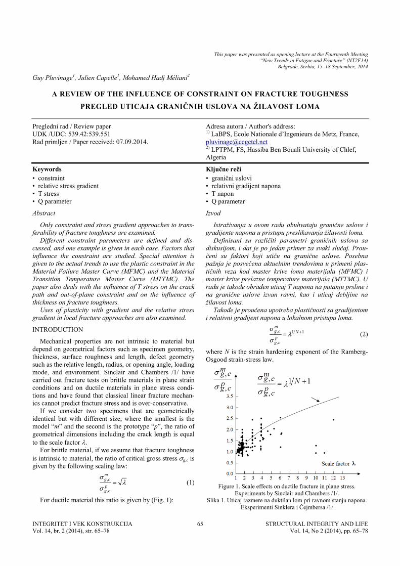
For ductile material this ratio is given by (Fig. 1):
, 1 1
,
mg c Npg c
(2)
where N is the strain hardening exponent of the Ramberg-Osgood strain-stress law.
Figure 1. Scale effects on ductile fracture in plane stress.
Experiments by Sinclair and Chambers /1/. Slika 1. Uticaj razmere na duktilan lom pri ravnom stanju napona.
Eksperimenti Sinklera i Čejmbersa /1/
INTEGRITET I VEK KONSTRUKCIJA Vol. 14, br. 2 (2014), str. 65–78
STRUCTURAL INTEGRITY AND LIFEVol. 14, No 2 (2014), pp. 65–78
A review of the influence of constraint on fracture toughness Pregled uticaja graničnih uslova na žilavost loma
Material properties available from databanks are there-fore to be considered as reference material properties, as results from standard tests. To use these reference proper-ties for a structure and component which differ in terms of geometry and loading mode, a correction needs to be made, which is called transferability.
The properties to be used in a structure Pstruct are deduced from reference properties Pref and the transferabil-ity function f(p), where p is the transferability parameter.
Pstruct = Pref f(p) (3) Evidence of the scale effect was first pointed out by
Leonardo da Vinci (1452-1519), and in the sixteenth cen-tury Galileo Galilei said that “from the small to the big is not so simple”.
The scale effect is generally represented by models using a characteristic dimension from the structures. For probabil-istic approaches /2/, the volume V of the structure, the scale factor /3/, or a characteristic length /3/ is used as an adjustable parameter.
A fractal approach to the scale effect on fracture tough-ness Gc was proposed by Carpinteri et al. /4/. It introduces a characteristic length lch which controls the transition from fractal to Euclidian behaviour.
Bazant /5/ has developed a scaling law based on an asymptotic and energetic approach. It refers to the critical stress, whose value is ruled by two asymptotic behaviours: plastic collapse without any scale effect, and brittle fracture where the scale effect is maximal. These two asymptotes intersect at a length D0, which characterizes the brittle-to-ductile transition.
For fractures emanating from a defect where fracture mechanics can be applied, the transferability is sometimes treated with the concept of characteristic length or scale factor /6/ but more often by using the stress constraint or the relative stress gradient. These transferability parameters emanate from the defect tip distribution (notch or crack). If we compare the stress distribution obtained in a reference situation (generally small scale yielding) with another gen-eral one, the stress distribution is modified in two ways: there is a shift of the stress distribution and a small rotation. These modifications of the stress distribution are considered as transferability problems. The shift of the stress distribu-tion is introduced into the plastic constraint, which is used as the transferability parameter. In literature, we can note the following constraint parameters: the plastic constraint factor L /7/, the stress triaxiality /8/, the Q parameter /9/, T stress /10/, and A2 /11/.
The rotation of the defect tip distribution is also less often used as a transferability parameter. The following parameters can be used: the strain gradient plasticity /12/, the defect tip relative stress gradient /13/, or the relative stress gradient /14/.
Today, there is no proposed approach combining these two aspects of the modification of the stress distribution with geometrical or loading mode parameters.
In this review paper, only constraint and stress gradient approaches to transferability are examined. For the charac-teristic length approaches, attention is focused instead on the scale effects /15/.
Different constraint parameters are defined and dis-cussed and one example is given in each case. Factors that influence constraint are studied. Special attention is given to the plastic constraint in the Material Failure Master Curve (MFMC) and the Transition Temperature Master Curve (TTMC). The paper also deals with the influence of T stress on the crack path and the influence of thickness on fracture toughness with the out-of-plane constraint.
The use of plasticity with gradient and the relative stress gradient in local fracture approaches is also examined.
CONSTRAINTS AT DEFECT TIP
Constraint is considered as a modification of the defect tip distribution under the effects of specimen or defect geometries or loading mode. Different constraint parame-ters are defined and associated with the defect type or stress-strain behaviour.
Singular elastic stress distribution
For a notch with infinite acuity, Williams /16/ has given a solution for elastic stress distribution as the following series:
1
1 ,( ) , ,n
ij n ij nn
Re A r f i j r
(4)
For a crack, Larson et al. /17/ have suggested describing the elastic stress field at the crack tip by three terms and introduce for the first time the T term as the second one of the series:
1 1( )2
ijij ij i j
Kf O r
r
(5)
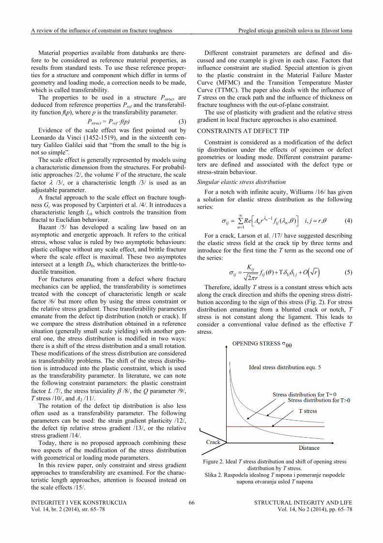
Therefore, ideally T stress is a constant stress which acts along the crack direction and shifts the opening stress distri-bution according to the sign of this stress (Fig. 2). For stress distribution emanating from a blunted crack or notch, T stress is not constant along the ligament. This leads to consider a conventional value defined as the effective T stress.
Figure 2. Ideal T stress distribution and shift of opening stress
distribution by T stress. Slika 2. Raspodela idealnog T napona i pomeranje raspodele
napona otvaranja usled T napona
INTEGRITET I VEK KONSTRUKCIJA Vol. 14, br. 2 (2014), str. 65–78
STRUCTURAL INTEGRITY AND LIFEVol. 14, No 2 (2014), pp. 65–78
66
A review of the influence of constraint on fracture toughness Pregled uticaja graničnih uslova na žilavost loma
Singular elastic-plastic stress distribution
The power-law expansion of the elastic-plastic HRR /18/ field if higher-order singular or non-singular terms are considered, is represented by:
1 2
2 1
(1) (2)
1 2
2 2 (3)2
ˆ ˆ( ) ( ) (, )
ˆ ( )
s s
ij ij ij
s s
ij
r rr A f A f
l l
rA f
l
(6)
with s1 = –1/(N + 1) and Â1 ~ J 1/(N+1), where N is the hard-ening exponent according to the Ramberg-Osgood consti-tutive equation, s2 is the exponent of the second singular or non-singular term, J is a path integral, and l is a reference length.
O'Dowd and Shih /19, 20/ have simplified this formula. Considering strain hardening exponent values in the range 5 ≤ N ≤ 20, the angular functions f and frr are equivalent and constant f ≈ frr ≈ constant, and the value of fr is negligible when compared with f (f >> fr) for | | < /2. The stress field is therefore described by:
1
1
0 0
( , ) ( , )/
qn
ij ij ijn
J rf n Q f n
B I r J
values of the difference between the opening stress yy and the stress parallel to the crack xx (see Table 1).
(7)
B0 and In are constants for fixed values of and n; q is a parameter close to zero (q ≈ 0); and 0 is the reference stress. The Q parameter is called the amplitude factor of the second-order field or simply Q.
Non-singular elastic and elastic plastic stress distribution
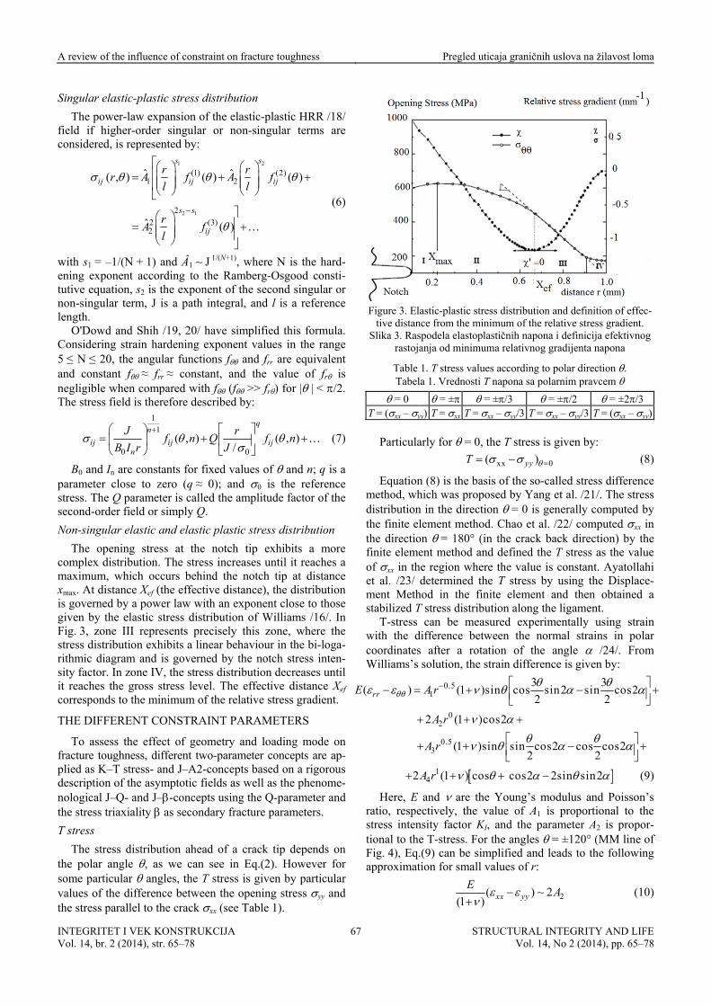
The opening stress at the notch tip exhibits a more complex distribution. The stress increases until it reaches a maximum, which occurs behind the notch tip at distance xmax. At distance Xef (the effective distance), the distribution is governed by a power law with an exponent close to those given by the elastic stress distribution of Williams /16/. In Fig. 3, zone III represents precisely this zone, where the stress distribution exhibits a linear behaviour in the bi-loga-rithmic diagram and is governed by the notch stress inten-sity factor. In zone IV, the stress distribution decreases until it reaches the gross stress level. The effective distance Xef corresponds to the minimum of the relative stress gradient.
THE DIFFERENT CONSTRAINT PARAMETERS
To assess the effect of geometry and loading mode on fracture toughness, different two-parameter concepts are ap-plied as K–T stress- and J–A2-concepts based on a rigorous description of the asymptotic fields as well as the phenome-nological J–Q- and J–-concepts using the Q-parameter and the stress triaxiality as secondary fracture parameters.
T stress
The stress distribution ahead of a crack tip depends on the polar angle , as we can see in Eq.(2). However for some particular angles, the T stress is given by particular
Figure 3. Elastic-plastic stress distribution and definition of effec-
tive distance from the minimum of the relative stress gradient. Slika 3. Raspodela elastoplastičnih napona i definicija efektivnog
rastojanja od minimuma relativnog gradijenta napona
Table 1. T stress values according to polar direction . Tabela 1. Vrednosti T napona sa polarnim pravcem
= 0 = ± = ±/3 = ±/2 = ±2/3 T = ( yy)xx – yy) T = xx T = xx – yy/3 T = xx – yy/3 T = (xx –
ar
difference ethod, which was proposed by Yang
dis
P l
articul y for = 0 tre
, the T s ss by
(8)
is given :
xx 0( )yyT
Equation (8) is the basis of the so-called stress m et al. /21/. The stress
tribution in the direction = 0 is generally computed by the finite element method. Chao et al. /22/ computed xx in the direction = 180° (in the crack back direction) by the finite element method and defined the T stress as the value of xx in the region where the value is constant. Ayatollahi et al. /23/ determined the T stress by using the Displace-ment Method in the finite element and then obtained a stabilized T stress distribution along the ligament.
T-stress can be measured experimentally using strain with the difference between the normal strains in polar coord inates after a rotation of the angle /24/. From Williams’s solution, the strain difference is given by:
0.51
3 3( ) 1 sin cos sin2 sin cos2
2 2( )rr A r
02
0.53
2 1 2
1 sin cos2 c
( )cos
( )sin os cos22 2
E
A r
A r
142 1 cos cos2( ) 2sin sin2A r (9)
Here, E and are the Young’s modulus and Poisson’s tio, respectively, the value of A1 is proportiona
stress inra l to the
tensity factor KI, and the parameter A2 is propor-tional to the T-stress. For the angles = ±120° (MM line of Fig. 4), Eq.(9) can be simplified and leads to the following approximation for small values of r:
2( ) ~ 2(1 ) xx yy
EA
(10)
INTEGRITET I VEK KONSTRUKCIJA Vol. 14, br. 2 (2014), str. 65–78
STRUCTURAL INTEGRITY AND LIFEVol. 14, No 2 (2014), pp. 65–78
67
A review of the influence of constraint on fracture toughness Pregled uticaja graničnih uslova na žilavost loma
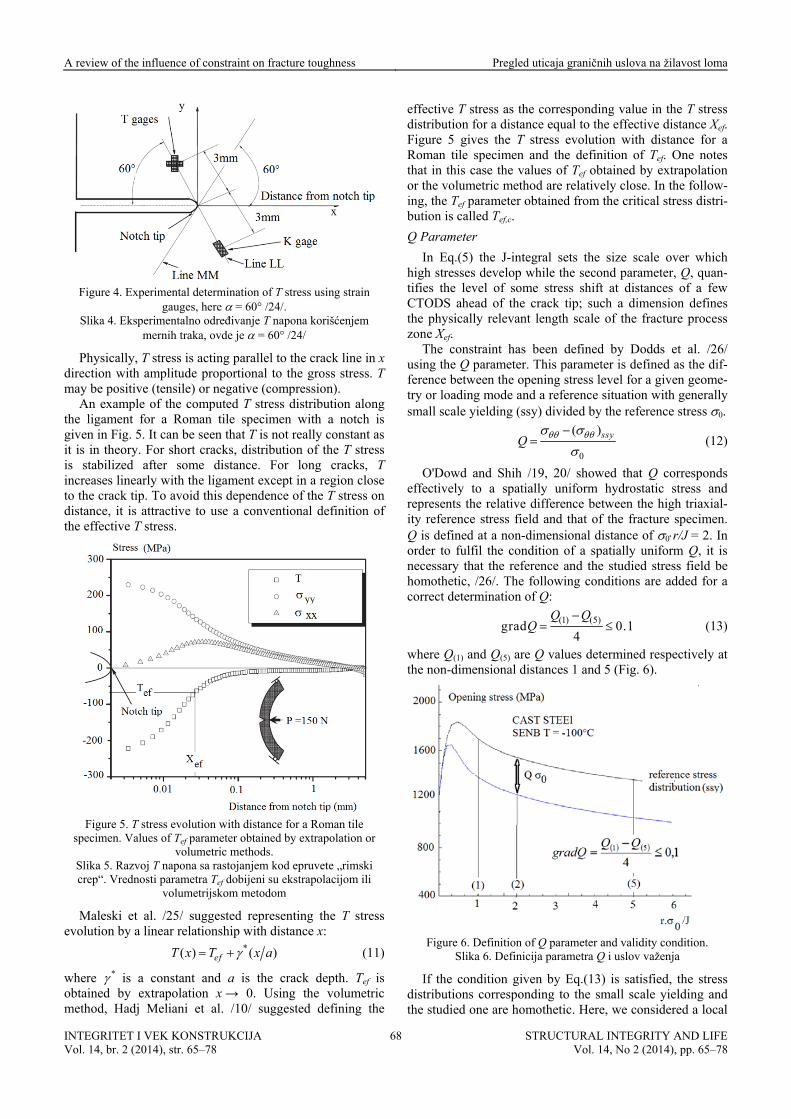
Figure 4. Experimental determination of T stress using strain
gauges, here = 60° /24/. Slika 4. Eksperimentalno određivanje T napona korišćenjem
x dir T may be positiv ion).
tant as it
mernih traka, ovde je = 60° /24/
tress is acting parallel to tPhysically, T s he crack line inection with amplitude proportional to the gross stress.
e (tensile) or negative (compressAn example of the computed T stress distribution along
the ligament for a Roman tile specimen with a notch is given in Fig. 5. It can be seen that T is not really cons
is in theory. For short cracks, distribution of the T stress is stabilized after some distance. For long cracks, T increases linearly with the ligament except in a region close to the crack tip. To avoid this dependence of the T stress on distance, it is attractive to use a conventional definition of the effective T stress.
Figure 5. T stress evolution with distance for a Roman tile
specimen. Values of Tef parameter obtained by extrapolation or volumetric methods.
S
s ev
lika 5. Razvoj T napona sa rastojanjem kod epruvete „rimskcrep“. Vrednosti parametra Tef dobijeni su ekstrapolacijom ili
volumetrijskom metodom
i
Maleski et al. /25/ suggested representing the T stresolution by a linear relationship with distance x:
*( ) ( )efT x T x a (11)
where * is a constant and a is the crack depth. Tef is btained by extrapolation x → 0. Usethod, Hadj Meliani et al. /10/ sug
while the second parameter, Q, quan-l of some stress shift at distances of a few
CT
tween the opening stress level for a given geome-try
o ing the volumetric m gested defining the
effective T stress as the corresponding value in the T stress distribution for a distance equal to the effective distance Xef. Figure 5 gives the T stress evolution with distance for a Roman tile specimen and the definition of Tef. One notes that in this case the values of Tef obtained by extrapolation or the volumetric method are relatively close. In the follow-ing, the Tef parameter obtained from the critical stress distri-bution is called Tef,c.
Q Parameter
In Eq.(5) the J-integral sets the size scale over which evelop high stresses d
tifies the leveODS ahead of the crack tip; such a dimension defines
the physically relevant length scale of the fracture process zone Xef.
The constraint has been defined by Dodds et al. /26/ using the Q parameter. This parameter is defined as the dif-ference be
or loading mode and a reference situation with generally small scale yielding (ssy) divided by the reference stress 0.
0
( )ssyQ
(12)
O'Dowd and Shih /19, 20/ showed that Q corresponds ffectively to a spatially uniform hy
represents the relative difference between the high triaxial-ity
e drostatic stress and
reference stress field and that of the fracture specimen. Q is defined at a non-dimensional distance of 0r/J = 2. In order to fulfil the condition of a spatially uniform Q, it is necessary that the reference and the studied stress field be homothetic, /26/. The following conditions are added for a correct determination of Q:
(1) (5)grad 0.14
Q QQ
(13)
where Q and Q are Q val(1) (5) ues determined respectively at e non-dimensional distances 1 and 5 (Figth . 6).
Figure 6. Definition of Q parameter and validity condition.
Slika 6. Definicija parametra Q i uslov važenja
If thnd
a local
e condition given by Eq.(13) is satisfied, the stress ributions corresponding to the small scale yielding adist
the studied one are homothetic. Here, we considered
INTEGRITET I VEK KONSTRUKCIJA Vol. 14, br. 2 (2014), str. 65–78
STRUCTURAL INTEGRITY AND LIFEVol. 14, No 2 (2014), pp. 65–78
68
A review of the influence of constraint on fracture toughness Pregled uticaja graničnih uslova na žilavost loma
Other constraint parameters
2 and A3 parameters
lution for stresses near the tip tic body can be written in the
fracture criterion for brittle fracture with two parameters, the critical stress c and the characteristic distance Xc. The characteristic distance is in this case independent of the stress distribution and is associated with a material charac-
teristic if we multiply the relationship (12) by cX :
( )yy c yy SSY c
y c
X XQ
X
(14)
d multiply again by the geometry correction
an factor F:
c Ic
y c
K KQ
X F
(15)
e can see that in this case Q is simpnce between critical stress intensity f
echan- or J–. Stress triaxiality is chosen as a
tra
w ly the relative differ-e actors.
Stress triaxiality
The stress triaxiality is also used as a measure of the ds to the two-parameter fracture mconstraint and lea
ics approach K–nsferability parameter because ductile fracture is sensi-
tive to this parameter through void growth /27/ as well as cleavage stress for brittle fracture /28/.
This parameter is defined as the ratio of the hydrostatic stress over the equivalent von Mises stress.
h
VM
(16)
where 3
xx yy zzh
(17)
and 2 2 22 3( ) (18) 1 3 1 2
1( ) ( )
2VM
The critical stress triaxiality distribution at the notch tip ases until it reaches a maximum, which for the
event is called and corresponds to distance X . After tha
h de
e fracture process zone.
re toughness with liga-me
incre critical max,c max,c
t, it decreases, then sometimes increases again, and final-ly falls to zero when the distance is far from the notch tip.
The maximum critical stress triaxiality is sensitive to the notch radius and ligament size. It decreases practically line-arly with the notch radius and increases with relative notc
pth /29/. It has been noted that the maximum triaxiality always occurs inside the fracture process zone since Xmax,c remains lower than or equal to the critical effective distance Xef,c /29/.
With an increase of the relative notch depth, the position of maximum stress triaxiality approaches or reaches the limit of th
According to /29/, the maximum stress triaxiality parameter is not the most suitable constraint parameter to explain the modification of fractu
nt size or thickness. An improvement has been made using the effective critical stress triaxiality ef,c. This pa-rameter is defined as the average value of the critical stress triaxiality over the critical effective distance Xef,c.
,
,0,
1( )
ef cX
ef cef c
x dxX
(19)
A
A three-term asymptotic soof the crack in an elastic-plasform /11/:
0 1 2 21 2 3
0
ij s t t sij ij ijA r f A r f A r f
(20)
where r is the dimensionless distance:
0r
rJ
(21)
0 ference stress. t and s are exponents, and is the re 0ijf ,
1ijf , and ij
2f are nfrom the solu
ormalized antions of asymptotic p 1
twthe p
gular functions obtained roblems. A and A 2 are
o independent amplitudes found by stress fitting inside fracture rocess volume.
10 0
1
1
sJ
A snI l n
(22)
The dimensionless integration constant In depends only
n the hardening exponent n and is indepmaterial constants (i.e. reference strain 0 or stress , res
o endent of other
pectively) and applied loads. L is a characteristic length parameter which can be chosen as the crack length a, the specimen width W, the thickness B, or unity. is a parame-ter of the Ramberg-Osgood law.
A3 depends on A1 and A2:
21
32
AA
A (23)
1A is re 2Alated to J, and is related and close to Q. The o t parameter c nstrain 2A
com is depari
teNi kov, /11/, by son of the actual radial and circu
e
rmined as presented by kish
mferential stresses distribution in the specimen and the stresses according to th reference asymptotic field at two points located in the ligament and at = /4, both at a distance of r = 2J/0. This procedure is identical to those used for Q determination.
3A can be used for a three-parameter fracture approach, K–T–A3 or J–A2–A3 /22, 30-31/.
Plastic constraint factor
The plastic constraint factor is used for determination of the limit state. The theory of limit analysis appeared in the
branch of the theory of plasticity rel
t stress N (load divided by the ligament cross-section) while brittle fracture
late 1930s. It constitutes aated to an elastic perfectly plastic behaviour. In the mid-
1950s a large number of analytical solutions appeared for calculating the ultimate load of beams and shells, leading to more realistic values of the capacity to resist plastic collapse.
The introduction of linear fracture mechanics in the mid-1950s led to consider the risk of brittle fracture governed by the global stress in apparent opposition to the theory of plastic collapse governed by the net stress.
This failure criterion assumes that failure occurs when a critical net stress N
c reaches the ultimate strength Rm. One notes that ductile failure is sensitive to ne
INTEGRITET I VEK KONSTRUKCIJA Vol. 14, br. 2 (2014), str. 65–78
STRUCTURAL INTEGRITY AND LIFEVol. 14, No 2 (2014), pp. 65–78
69
A review of the influence of constraint on fracture toughness Pregled uticaja graničnih uslova na žilavost loma
is
wer bound of a plot of experimenconstraint
fac
iameter.
sensitive to gross stress g (load divided by the entire section). The above-mentioned criterion needs to be modi-fied to take into account constraints due to geometry and loading mode effects in the following manner:
cN mL R (24)
where L is the so-called plastic constraint factor. Design codes are based on limit analysis to calculate the
mit state and incorporate the safety factoli r through the lo tal results.
Figure 7 gives the evolution of the plastic tor in a polyethylene pipe with a semi-elliptical surface
defect. The plastic constraint factor L is plotted versus the relative defect depth a/D, where D is the pipe d
Figure 7. Evolution of the plastic constraint factor versus the
relative defect depth a/D. Polyethylene pipe, /7/. Slika 7. Razvoj faktora plastičnog graničnog uslova prema
stress has a strong influence on the shape and size lastic zone /30/. For example, in plane strain the plas
utterfly wing. For a pozone has a typical shape of a bT stress the wings are oriented
n. If the T stress is negative, the wings are oriented in the reverse crack extension direction, /31/.
This effect is illustrated in Fig. 8, showing the plastic zone ahead of a surface notch defect. This defect is located in a pipe of diameter D and thickness B (B = 8.9 cm). The applied internal pressure is 20 bar.
The size of the plastic zone is also modified because the equivalent stress is modified by the T stress. If we consider the asymptotic field given by Eq.(3) and = , the equiva-lent von Mises stresseq is a functio I
21 27 1 14 21( , 0, ) 13 3 28 282
Ieq
I
K T rr
Kr
(25)
When T is negati e (specimen in tension), the plast
v ic zone increases compared to the reference case for whicT = 0. For positive values of T (double cantilever beaDCB, or compact tension, CT, specimen), the size of the pla
ation A .
h m,
stic zone decreases. Mostafavi et al., /32/ have suggested a new constraint
parameter defined as the ratio of the current plastic zone
area Ap,c and the reference plastic zone area, that is, for a small scale yielding situ p,ssy
,
,
p c
p ssy
A
A (26)
a/t = 0.1 R/t = 20 T < 0
a/t = 0.75 R/t = 20 T > 0
Figure 8. Influence of T stress sign on plastic zone shape. Slika 8. Uticaj predznaka T napona na oblik plastične zone
Mostafavi et a he constraint pa-rame aint at a st-ed w pa
l., /32/, remarked that tlimitation in characteriziter has its ng the constr
higher J-integral value for ductile material and suggethat the constraint definition be modified by a ne
rameter Ap:
,
,
p cp
p ref
AA
A
(27)
Ap,c is the area surrounded by the equivalent plastic strain (p) isolines ahead of the crack tip and Ap,ref is the reference area surrounded by the (p) isolines in a standard test.
INTEGRITET I VEK KONSTRUKCIJA Vol. 14, br. 2 (2014), str. 65–78
STRUCTURAL INTEGRITY AND LIFEVol. 14, No 2 (2014), pp. 65–78
70
A review of the influence of constraint on fracture toughness Pregled uticaja graničnih uslova na žilavost loma
Yang et al. /33/ found that a sole line ratio of the current and the refer
JC/Jref exists. This is restricted to the case for dissimilar
alues an
ear relation between th ence fracture toughness
metal welded joints regardless of the in-plane and out-of-plane constraints for a crack. This relationship is independ-ent on the selection of the p isolines for higher p v
d can be regarded as a unified reference line to character-ize the dependence of fracture resistance of a crack on the constraint (Fig. 9).
Figure 9. Normalized fracture resistance JC/Jref versus √Ap for cracked dissimilar metal welded joints, obtained from p = 1.0
isolines, /33/. Slika 9. Normalizovana otpornost prema lomu JC/Jref sa √Ap za
naprsle zavarene spojeve raznorodnih metala, dobijeno iz p = 1,0 izolinija, /33/
FA
e s t
are given as follows.
s of specimens are examined: single ile (SENT), CT, Roman tile (RT), and DCB.
CTORS OF INFLUENCE ON CONSTRAINT
Values of the constraints Tef, Q, and stress triaxiality arensitive to specimen geometry, loading mode, ligamen
size, and load level, /34/. Some examples of these effects
Loading mode
It has been noted that T stress can be negative or posi-tive. In Table 2, the critical effective T stress for four speci-mens used for fracture test has been reported. These speci-mens have a notch of 0.25 mm radius and are made in X 52 pipe steel. Four typeedge notch tens
Table 2. Values of Tef,c/y for four specimen types (SENT, CT, RT, and DCB).
Tabela 2. Vrednosti Tef,c/y za četiri tipa epruveta (SENT, CT, RT, i DCB)
In general, specimens loaded in tension like CCT or e
er ne e T st g constrai 0/. a
w u
meter Tef distribu-en (width W = 63.80 mm, height =
61
stant for each nd equal to 1000 N. The value of effective T
str
SENT have a high n gative effective T stress and are there-fore less constrained. Specimens in bending like TPB or CT
reshave lowDCB alw
gativ has po
s and hi her he n
nt, /1ys sitiv
ss the conseqe values. In
uence for cra t ext
ck bifurcatiosection, wen. ill disc
For the CT specimen, some contradictory results can be found in literature, /35/. The effective T stress is sometimes negative and sometimes positive. These differences can be explained by the definition of the effective T stress, the ligament size, the load level, and so on.
Thickness
The effect of thickness on constraint is explained later as the effect of out-of-plane constraint, /35/.
Ligament size
Figure 10 depicts the constraint paration for the CT specim
mm, thickness = 5.84 mm, notch radius = 0.25 mm) in plane stress. The relative notch depth a/W varies in the
and the applied load is conrange 0.1 to 0.7value of a/W a
ess Tef is associated with the effective distance, which varies with a/W, /10/.
Figure 10. Tef distribution for CT specimen (width W = 63.80 mm, height 61 mm, thickness 5.84 mm, notch radius 0.25 mm) in plane
stress, /10/. Slika 10. Tef raspodela za CT epruvetu (širina W = 63,80 mm,
visina 61 mm, debljina 5,84 mm, poluprečnik zareza 0,25 mm) pri ravnom stanju napona, /10/
and
0
b is the ligament size. The cate that, in gen-era
e T stress, all non-linear curve, which is
the
One notes that the value of Tef increases when a/W increases. This result is confirmed by /40/, where T, Q, ,
or a clampA2 are computed f ed single-edge tension specimen. The relative crack depth varies in the range a/W = 0.3–0.7 at the loading level of J/(b ) = 0.01, where
se authors indil, T, –Q, , and –A2 increase as a/W increases; however,
the impact of a/W is relatively small.
Loading path in plane Kap-Tef
A negative value of the Tef -parameter increases with the applied load generally according to a parabolic function for low values of the applied load or pressure and becomes practically linear when the load value increases. In the
factor-effectivplane applied stress intensity the assessment points follow a
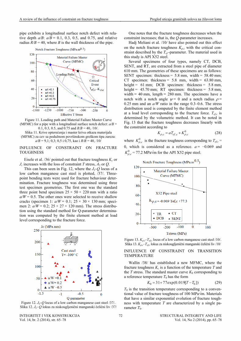
so-called loading path. The loading path intercepts the MFMC at the point K,c–Tef,c -parameter (or Kc if the defect is a crack) at the critical event. Figure 11 gives an example of different loading paths for a pipe made of X52 steel. The
INTEGRITET I VEK KONSTRUKCIJA Vol. 14, br. 2 (2014), str. 65–78
STRUCTURAL INTEGRITY AND LIFEVol. 14, No 2 (2014), pp. 65–78
71
A review of the influence of constraint on fracture toughness Pregled uticaja graničnih uslova na žilavost loma
pipe exhibits a longitudinal surface notch defect with rela-tive depth a/B: a/B = 0.1, 0.3, 0.5, and 0.75, and relative radius R/B = 40, where B is the wall thickness of the pipe.
Figure 11. Loading path and Material Failure Master Curve
(MFMC) for a pipe with a longitudinal surface notch defect: a/B = 0.1, 0.3, 0.5, and 0.75 and R/B = 40, /10/.
Slika 11. Krive opterećenja i master kriva otkaza materijala (MFMC) za cev sa podužnom površinskom greškom tipa zareza:
a/B = 9,1; 0,3; 0,5 i 0,75, kao i R/B = 40, /10/
IN
This c cus of a
re toughness was determined using three tes
tio a/W
FLUENCE OF CONSTRAINT ON FRACTURE TOUGHNESS
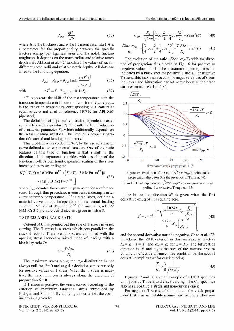
Eisele et al. /36/ pointed out that fracture toughness Kc or Jc increases with the loss of constraint T stress, A2 or Q.
an been seen in Fig. 12, where the JC-Q lolow carbon manganese cast steel is plotted, /37/. Three-point bending tests were used for fracture behaviour deter-mination. Fractu
t specimen geometries. The first one was the standard three point bend specimen 25 × 50 × 220 mm with a ra
= 0.5. The other ones were selected to receive shallow cracks (specimen 1: a/W = 0.1; 25 × 30 × 130 mm; speci-men 2: a/W = 0.2; 25 × 27 × 120 mm). The stress distribu-tion using the standard method for Q-parameter determina-tion was computed by the finite element method at load level corresponding to the fracture force.
Figure 12. JC-Q locus of a low carbon manganese cast steel /37/.
Slika 12. JC–Q lokus za niskougljenični manganski čelični liv /37/
One notes that the fracture toughness decreases when the constraint increases; that is, the Q-parameter increases.
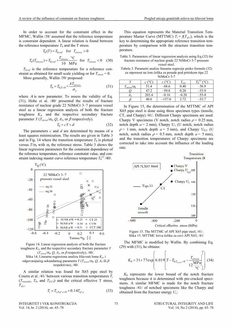
Hadj Meliani et al. /10/ have also pointed out this effect on the notch fracture toughness K,c with the critical con-straint described by the Tef -parameter. The material used in this study is API X52 steel.
Several specimens of four types, namely CT, DCB, SENT, and RT, are extracted from a steel pipe of diameter 610 mm. The geometries of these specimens are as follows: SENT specimen: thickness = 5.8 mm, width = 58.40 mm; CT specimen: thickness = 5.8 mm, width = 63.80 mm, height = 61 mm; DCB specimen: thickness = 5.8 mm, height = 45.70 mm; RT specimen: thickness = 5.8 mm, width = 40 mm, length = 280 mm. The specimens have a notch with a notch angle = 0 and a notch radius = 0.25 mm and an a/W ratio in the range 0.3–0.6. The stress d
det
istribution used is computed by the finite element methodat a load level corresponding to the fracture force. Tef,c is
ermined by the volumetric method. It can be noted in Fig. 13 that the fracture toughness decreases linearly with the constraint according to
0, , ,c ef c cK aT K (28)
where 0,cK is the fracture toughness corresponding to Tef,c =
0, which is considered as a reference. a = −0.069 and 0
,cK = 77.2 MPam for the API X52 pipe steel.
e 13. K,c–Tef,c locus of a low carbon manganese caFigur st steel /10/.
Slika 13. K,c–Tef,c lokus za niskougljenični manganski čelični liv /10/
INFLUENCE OF CONSTRAINT ON TRANSITION TEMPERATURE
Wallin /38/ has established a new MFMC, where the fracture toughness Kc is a function of the temperature T and the T stress. The standard master curve K0 corresponding to a reference temperature T0 has the form
0 031 77exp(0.019[ ])K T T (29)
T0 is the transition temperature corresponding to a conven-tional value of fracture toughness of 100 MPa√m. Materials that have a similar exponential evolution of fracture tough-ness with temperature T are characterized by a single pa-rameter T0.
INTEGRITET I VEK KONSTRUKCIJA Vol. 14, br. 2 (2014), str. 65–78
STRUCTURAL INTEGRITY AND LIFEVol. 14, No 2 (2014), pp. 65–78
72
A review of the influence of constraint on fracture toughness Pregled uticaja graničnih uslova na žilavost loma
In order to account for the constraint effect in the MFMC, Wallin /38/ assumed that the reference temperature is constraint dependent. A linear relation is found between the reference temperature T0 and the T stress.
0 0,( ) for 0ref stressT T T T
0 0,C
( ) + for 010 MPastress
stress ref stressT
T T T T
(30)
T0,ref is the reference temperature for a reference con-straint as obtained for small scale yielding or for Tstress = 0.
More generally, Wallin /39/ proposed:
0 0, 0 + stressT
y
ATT T
(31)
where is new parameter. To assess the validity of Eq. (31), Hohe et al. /40/ presented the results of fracture
(32)
Table 3 shows the near regression parameters for the constraint
resistance of nuclear grade 22 NiMoCr 3–7 pressure vessel s ea teel as a lin r regression analysis of both the fracturetoughness K and the respective secondary fractureJc
parameter Y (Tstress/0, Q, A2, or respectively).
0T cY d
The parameters c and d are determined by means of a least squares minimization. The results are given in Table 3 and in Fig. 14 where the transition temperature T0 is plotted versus T/0 with 0 the reference stress.li dependence of the reference temperature, reference constraint value, and con-straint indexing master curve reference temperature T0
CI /40/.
Figure 14. Linear regression analysis of both the fracture
toughness KJc and the respective secondary fracture parameter Y (Tstress/0, Q, A2, or respectively), /40/.
Slika 14. Linearna regresiona analiza žilavosti loma KJc i odgovarajućeg sekundarnog parametra Y (Tstress/0, Q, A2 ili
respektivno), /40/
A similar relation was found Co
key to determining the appropriate reference transition tem-perature by comparison with the structure transition tem-perature.
Table 3. Parameters of linear regression analysis using Eq.(32) for fracture resistance of nuclear grade 22 NiMoCr 3-7 pressure
vessel steel. Tabela 3. Parametri analize linearne regresije preko formule (32)
za otpornost na lom čelika za posude pod pritiskom tipa 22 NiMoCr 3-7
Y c (°C) c (°C) Yref T0CI (°C)
for X65 pipe steel by seru et al. /41/ between various transition temperatures Tt
(Tt,tensile, T0, and TK1/2) and the critical effective T stress, Tef,c.
, . 0 ,0.14t t Tef c ef cT T T (33)
This equation represents the Material Transition Tem-perature Master Curve (MTTMC) Tt = f(Tef,c), which is the
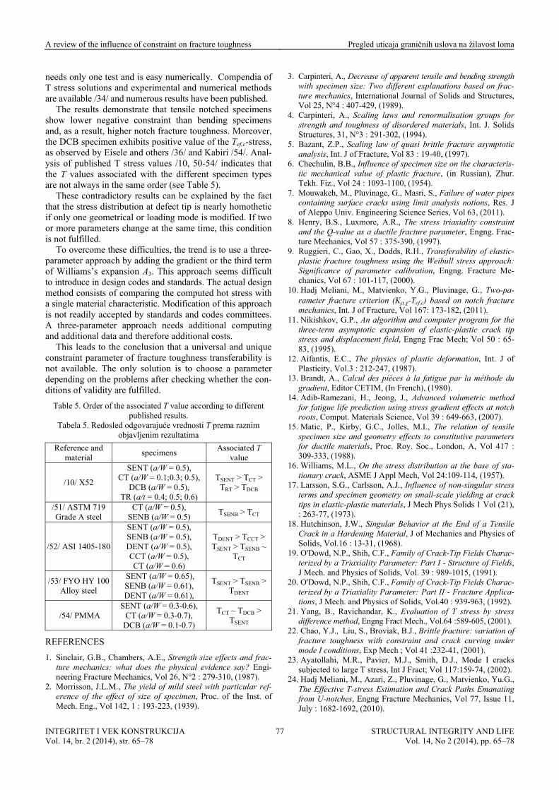
In Figure 15, the determination of the MTTMC of API X65 pipe steel is done using three specimen types (tensile, CT, and Charpy) /41/. Different Charpy specimens are used: Char m, n 0.5
notc m), an e corrected to take into uence of the loading
py V specimens (V notch, notch radius = 0.25 motch depth a = 2 mm), Charpy U1 (U notch, notch radius = 1 mm, notch depth a = 5 mm), and Charpy U (U
h, notch radius = 0.5 mm, notch depth a = 5 md the transition temperatures of Charpy specimens ar
account the inflrate.
Fi ureg
a 15. TTM I X6 steel,
15. M kriv za c I X65,
Th FMC difie alli comb . (29
The M C of AP 5 pipe /41/. Slik TTMC a čelika evi AP /41/
e M is mo d by W n. By ining Eq) with (31), he obtains:
0 0, 031 77exp 0.019MPa
12°C
stress
stressT
TK T T
(34)
K0 represents the lower bound of the notch fracture toughness because it is determined with pre-cracked speci-mens. A similar MFMC is made for the notch fracture toughness /41/ of notched specimens like the Charpy and obtained from the fracture energy Uc:
INTEGRITET I VEK KONSTRUKCIJA Vol. 14, br. 2 (2014), str. 65–78
STRUCTURAL INTEGRITY AND LIFEVol. 14, No 2 (2014), pp. 65–78
73
A review of the influence of constraint on fracture toughness Pregled uticaja graničnih uslova na žilavost loma
,c
cU
JBb
(35)
where B is the thickness and b the ligament size. Eta () is a parameter for the proportionality between the specific fracture energy per ligament area and the notch fracture toughness. It depends on the notch radius and relative notch depth a/W. Akkouri et al. /42/ tabulated the values of eta for different notch radii and relative notch depths. All data are fitted to the following equation:
*
, , ,,
( )tanhc J J
K
TJ A B
c
(36)
with , (37)
T* represents the shift of the test temperature with the transition temperature in function of constraint Tef,c. T ef,c=0 is the tran aint equal X65 pipe s
T0(Y) results in the introduction of a material parameter T0, which additionally depends on the actual loading situation. This implies a proper separa-
on of material and loading parameters. This problem was avoided in /40/, by the use of a master
curve defined as an exponential function. One of the basic fea
,
*, 0 0.14
ef ct T ef cT T T T
t,T
strsition temperature corresponding to a conto zero and used as reference (197 K for API teel).
The definition of a general constraint-dependent master curve reference temperature
ti
tures of this type of function is that a shift in the direction of the argument coincides with a scaling of the function itself. A constraint-dependent scaling of the stress intensity factors according to:
1 2( , ) 30 MPa m ( )refJJK T Y K T 1 230 MPa m
exp 0.019 ( )refc Y Y
Cotterel /43/ has pointed out the role of T curving. The T stress is a stress which acts parallel to the
direction. Therefore, this stress comng stress induces a mixed mode of
bia
(38)
where Yref denotes the constraint parameter for a reference case. Through this procedure, a constraint indexing master curve reference temperature T0
CI is established, defining a material curve that is independent of the actual loading situation. Values of Yref and T0
CI for nuclear grade 22 NiMoCr 3-7 pressure vessel steel are given in Table 3.
T STRESS AND CRACK PATH
stress in crack
crack bined with the openi loading with a
xiality ratio :
I
T a
K
(39)
The maximum stress along the distribution is not alw
ays null for = 0 and angular deviation can occur only for positive values of T stress. When the T stress is nega-tive, the maximum is always along the direction of propagation = 0.
If T stress is positive, the crack curves according to the criterion of maximum tangential stress introduced by Erdogan and Sih, /44/. By applying this criterion, the open-ing stress is given by
23 1 3 cos cos sin
4 2 4 2(
2)IK
Tr
(40)
2 2 3 1 3 2 cos cos sin4 2 2
)4
(I I
r T r
K K
(41)
The evolution of the ratio 2 r ·/KI with the direc-tion of propagation is plotted in Fig. 16 for positive or negative values of T. The maximum opening stress is indicated by a black spot for positive T stress. For negative T stress, this maximum occurs for negative values of open-ing stress and bifurcation cannot occur because the crack surfaces cannot overlap, /48/.
Figure 16. Evolution of the ratio 2 r ·/KI with crack direction in the presence of T stress, /45/. propagation
Slika 16. Evolucija odnosa 2 r ·/KI prema pravcuprsline u prisustvu T napona, /45/
The bifurcation direction * is given when derivative of Eq.(41) is equal to zero.
razvoja
the first
2
* 12
10241 1
9cos
512
9
cef
Ic
cef
Ic
TX
K
TX
K
(42)
and the second derivative must be negative. Chao et al. /22/ introduced the RKR criterion in this analysis. At fracture KI = Kc, T = Tc and = c for x = Xef. The bifurcation direction is * and Xef is the size of the fracture process volume or effective distance. The condition on the second derivative implies that for crack curving
3 1
8 2
c
c ef
T
K X (43)
Figures 17 and 18 give an example of a DCB specimen with positive T stress and crack curving. The CT specimen also has a positive T stress and non-curving crack.
For negative T stress, after initiation, the crack propa-gates firstly in an instable manner and secondly after sev-
INTEGRITET I VEK KONSTRUKCIJA Vol. 14, br. 2 (2014), str. 65–78
STRUCTURAL INTEGRITY AND LIFEVol. 14, No 2 (2014), pp. 65–78
74
A review of the influence of constraint on fracture toughness Pregled uticaja graničnih uslova na žilavost loma
eral millimetres in a stable manner. During crack propaga-tion in a stable manner, crack tip opening angle CTOA remains constant and its constant value is a characteristic of the fracture resistance of the material. It can be noted that during the stable crack propagation, both CTOA and T stress are constant (Fig. 19).
Fi g
9; Xef
izazvanim T
gure 17. DCB with positive T-stress-induced crack curvinT/K = +7. = 0.53 mm.
Slika 17. DCB epruveta sa pozitivnim skretanjem prsline, naponom, T/K = +7,9; X = 0,53 mmef
Figure 18. CT with positive T-stress-induced crack curving T/K =
+2.05; Xef = 0.49 mm. Slika 18. CT epruveta sa pozitivnim skretanjem prsline, izazvanim
T naponom, T/K = +2,05; Xef = 0,49 mm
Figure 19. Evolution of CTOA and T stress during crack
propagation. Steel API 5L X65. Slika 19. Razvoj CTOA i T napona pri rastu prsline. Čelik API 5L
X65
EFFECT OF THICKNESS ON FRACTURE TOUGHNESS AND OUT-OF-PLANE CONSTRAINT
It is well known now that fracture toughness (Kc or Jc) decreases when the thickness increases. The fracture tough-
ness is maximal for plane stress conditions and trends asymptotically to a minimum called KIc or JIc if the plane strain conditions are satisfied. Therefore a description of fracture resistance cannot be done with a single parameter. Zhao and Guo /46/ proposed to describe the effect of thick-ness B on fracture toughness Kc = f(B) by introducing ‘a triaxial stress constraint’ Tz. This parameter is defined as:
zzz
yy xx
T
(44)
For a straight crack through the thickness, which is a typical case of 3D cracks, y is the direction normal to tcr , Tz ranges from 0 stress state, and Tz = rd-ening e rela-tionship.
In order to take into account the thickness effect, it is necessary to have 3D descriptions of the singularity and angular distribution of stresses and strains as a function of the triaxial stress constraint Tz:
he ack plane x0z. In an isotropic linear elastic cracked body
to N, Tz = 0 for the plane N for the plane strain state, where N is the strain ha
xponent of the Ramberg-Osgood strain-stress
1/ 1
0 0
/ 1
0 0
3( ),
( , )ij ij zz
JT
I T N r
,( , )
( )
2
N
ij ij zz
N N
JT
I T N r
(45)
may be path z N. is the coefficient of the Ramberg-Osgood law; 0 the refer-ence stress, and 0 the strain associated to the reference stress.
These forms are similar to that of an HRR solution, but J
dependent and I is a function of T and
),(ij zT and ),(ij zT are eigenvalues. I is a complex
function of eigenvalues of stresses and displacements. With this kind of stress distribution the T stress depends
on relative thickness zB = z/B and is expressed as
( , )g BT T z (46)
ctionwhere the fun T presents a non-dimensional function and can be given as:
1 20
3
exp( (
), ) B
BB z B
T z BB
(47)
B0, B1, B2, and B3 are coefficients in function of the Poiss n ratio
For a pure nd Guo /46/
plane stress constraint Tz. The thickness-dependent fracture
z
e of a plate with a thi
o .
mode I cracked plate, Zhao adeveloped a 3D fracture criterion considering the out-of-
toughness is predicted using the equivalent thickness con-cept. This means that the in-plane distribution of T at the point P is the same as that at the mid-plan
ckness of Beq:
21eq BB z (48)
The three-dimensional fracture toughness in the pure mode I, KIz,c, is a function of the fracture toughness associ-ated with different thicknesses as:
, ( ) ( ) Iz c c zI eqK K B T Bf (49)
INTEGRITET I VEK KONSTRUKCIJA Vol. 14, br. 2 (2014), str. 65–78
STRUCTURAL INTEGRITY AND LIFEVol. 14, No 2 (2014), pp. 65–78
75
A review of the influence of constraint on fracture toughness Pregled uticaja graničnih uslova na žilavost loma
2
12 4(1 ) (1 2 )
3 3(
1 2) zI
zI eqT
f TT
B
(50
zI )
0 0 zI zI
p eqr B
where
1 p eqr B
T T dzdr (51)
pr is the mean radius of the crack-tip plastic zone
along the thickness. Zhao and Guo /46/ have tested this model on LY12-CZ
aluminium alloy standard CT specimens. Figure 20 indi-cates that the fracture toughness of this alloy is stronglyde
pendent on the thickness. After considering the equiva-
lent thickness Beq from Eq.(48), we can find that the three-dimensional fracture toughness in pure mode I, KIz,c, is almost a constant and is independent of the thickness.
Figure 20. Determination of the 3-dimensional fracture toughness
in pure mode I, KIz,
Slika 20. Određivanje trodimenc, on LY12-CZ aluminium alloy, /46/.
zionalne žilavosti loma u uslovima opterećenja tipa I, KIz,c, kod legure aluminijuma L
CONCLUSION
have been published on these parameters hich confirm their applicability.
sim
n is only used for elastic ituations but is often extended to elastic pla
Q is used only for elastic plastic fracture. We have seen at for pure brittle fracture, the Q parameter reduces to a lative difference of fracture toughness KIc (Eq.(15L is used strictly for plastic collapse in order to calculate
limit load.
Stress triaxiality is used for any stressDetermination of T stress needs only
advantage compared with the Q parameter.
is is particularly interesting in
f the relative shift of the opening stress distribution at defect tip. It suffers from the following problems: i) its definition is purely conventional at a non-dimensional distance of (0r/J = 2) which rarely corresponds to the char-acteristic or the effective distance. ii) Q is valid with a condition of homothety of the stress
istribution given by Eq.(13). For low strength steels, this condition is not generally fulfilled.
Q determination needs two tests, the second as reference, which has to be performed according to small-scale yield-ing conditions. This is not easy to realise if the material does not have the required thickness.
The plastic constraint L represents the elevation of the net stress compared with the gross stress. It is difficult to define the net stress value which should be taken into account because the stress distribution is not constant over th
methxiality has the main advantage that it can
be
ff
Y12-CZ, /46/
Most of the problems of transferability in fracture tough-ness can be treated with the help of a constraint parameter or a characteristic length.
If a constraint parameter is required, the question arises - which of the different possibilities to choose (T, Q, , L, A2, AP, , and so on).
The constraint parameters AP and have been very recently introduced, in 2011 and 2014 respectively /32, 33/. No other papers w The parameter A2 is
ilar to T (T = 4A2). In the light of these considerations, our discussion will be focused on the following four param-eters: T, Q, , L.
T stress according to its definitios stic fracture.
thre )). e
strain behaviour. a single fracture
test. This is anndA seco advantage is that it can be determined numeri-
cally or experimentally. Ththe case of a complex part of a structure. The major diffi-culty with the T stress concept is that T stress is not con-stant along a ligament ahead of a defect. Therefore a con-ventional value is needed. It has been proposed to use the effective distance, /10/, or extrapolation of the T stress evolution to origin, /25/, but these two definitions are not always in agreement.
The point of the Q parameter is to obtain an idea o
d
e ligament. Several definitions can be used: the maximlocal stress, the effective stress or the average stress. A
um
comparison of these definitions has been made by /7/. A definition based on a local failure criterion, the volumetric
od, is certainly a more realistic one. The stress tria used for any kind of failure (brittle, elastic plastic or
plastic collapse). Because the stress triaxiality varies along the ligament, a conventional definition of the prescribed value is also necessary (this value can be the value of the maximum or correspond to the effective distance). Its sensi-tivity to geometrical parameters /49/ such as the relative defect length reduces its interest as a reliable constraint parameter.
Eisele and others /36/ have suggested that fracture tough-ness is a decreasing function of constraints T and Q. In order to answer this question, Hohe and others /40/ tested four two-parameter approaches, the K–T stress-, J–Q-, J–A2, and J–-concepts. They found that all four approaches are able to characterise the local constraint situation of the different specimen geometry types considered. In a master curve analysis, they showed that the master curve reference temperature depends approximately linearly on the respec-tive secondary fracture parameters of all four concepts. This result was confirmed for notch fracture toughness versus critical effective T stress, Tef,c, /10, 41/. The linear relation-ship between the transition temperatures and the critical
ective T stress has been confirmed by /38-41/. With regard to the literature, the T stress is used most
often. Its popularity is probably because its determination
INTEGRITET I VEK KONSTRUKCIJA Vol. 14, br. 2 (2014), str. 65–78
STRUCTURAL INTEGRITY AND LIFEVol. 14, No 2 (2014), pp. 65–78
76
A review of the influence of constraint on fracture toughness Pregled uticaja graničnih uslova na žilavost loma
needs only one test and is easy numerically. Compendia of T stress solutions and experimental and numerical methods are available /34/ and numerous results have been published.
The results demonstrate that tensile notched specimens show lower negative constraint than bending specimens and, as a result, higher notch fracture toughness. Moreover, the DCB specimen exhibits positive value of the Tef,c-stress, as observed by Eisele and others /36/ and Kabiri /54/. Anal-ys
ble 5).
ode is modified. If two
e trend is to use a three-pa
puted hot stress with a s
is of published T stress values /10, 50-54/ indicates that the T values associated with the different specimen types are not always in the same order (see Ta
These contradictory results can be explained by the fact that the stress distribution at defect tip is nearly homothetic if only one geometrical or loading mor more parameters change at the same time, this condition is not fulfilled.
To overcome these difficulties, thrameter approach by adding the gradient or the third term
of Williams’s expansion A3. This approach seems difficult to introduce in design codes and standards. The actual design method consists of comparing the com
ingle material characteristic. Modification of this approach is not readily accepted by standards and codes committees. A three-parameter approach needs additional computing and additional data and therefore additional costs.
This leads to the conclusion that a universal and unique constraint parameter of fracture toughness transferability is not available. The only solution is to choose a parameter depending on the problems after checking whether the con-ditions of validity are fulfilled.
Table 5. Order of the associated T value according to different published results.
Tabela 5. Redosled odgovarajuće vrednosti T prema raznim objavljenim rezultatima
1. Sinclair, G.B., Chambers, A.E., Strength size effects and frac-ture mechanics: what does the physical evidence say? Engi-neering Fracture Mechanics, Vol 26, N°2 : 279-310, (1987).
2. Morrisson, J.L.M., The yield of mild steel with particular ref-erence of the effect of size of specimen, Proc. of the Inst. of
24
Mech. Eng., Vol 142, 1 : 193-223, (1939).
3.
. 6.
plastic deformation, Int. J of
13
14. od r ient
Materials Science, Vol 39 : 64915. M Kirby, G.C., J I., The relation of tensile
specimen size and g onstitutive parameters fo ater d : 309-333, (1988).
16. Williams, M.L., On the stress distribution at the base of sta-SME 24:109
17. Carl of non ss terms and specimen cale yielding at crack tips in elastic-plastic hys Solids 1 Vol (21),
18. Hutchinson, J.W., Singular Behavior at the End of a Tensile Crack in a Hardening echanics and Physics of
3-hih k-T
t riaxia - Struct ields, J Mech. and Physi -1
20. ., Shih ck-Ti c-terized by a Triaxia I - Fracture Applica-
d Physics of Solids, Vol.40 : 939-963, (1992). ichandar, K., Evaluation of T stress by stress
Carpinteri, A., Decrease of apparent tensile and bending strength with specimen size: Two different explanations based on frac-ture mechanics, International Journal of Solids and Structures, Vol 25, N°4 : 407-429, (1989).
4. Carpinteri, A., Scaling laws and renormalisation groups for strength and toughness of disordered materials, Int. J. Solids Structures, 31, N°3 : 291-302, (1994).
5. Bazant, Z.P., Scaling law of quasi brittle fracture asymptotic analysis, Int. J of Fracture, Vol 83 : 19-40, (1997)Chechulin, B.B., Influence of specimen size on the characteris-tic mechanical value of plastic fracture, (in Russian), Zhur. Tekh. Fiz., Vol 24 : 1093-1100, (1954).
7. Mouwakeh, M., Pluvinage, G., Masri, S., Failure of water pipes containing surface cracks using limit analysis notions, Res. J of Aleppo Univ. Engineering Science Series, Vol 63, (2011).
8. Henry, B.S., Luxmore, A.R., The stress triaxiality constraint and the Q-value as a ductile fracture parameter, Engng. Frac-ture Mechanics, Vol 57 : 375-390, (1997).
9. Ruggieri, C., Gao, X., Dodds, R.H., Transferability of elastic-plastic fracture toughness using the Weibull stress approach: Significance of parameter calibration, Engng. Fracture Me-chanics, Vol 67 : 101-117, (2000).
10. Hadj Meliani, M., Matvienko, Y.G., Pluvinage, G., Two-pa-rameter fracture criterion (K-Tef,c) based on notch fracture mechanics, Int. J of Fracture, Vol 167: 173-182, (2011).
11. Nikishkov, G.P., An algorithm and computer program for the three-term asymptotic expansion of elastic-plastic crack tip stress and displacement field, Engng Frac Mech; Vol 50 : 65-83, (1995).
12. Aifantis, E.C., The physics of Plasticity, Vol.3 : 212-247, (1987).
. Brandt, A., Calcul des pièces à la fatigue par la méthode dugradient, Editor CETIM, (In French), (1980). Adib-Ramezani, H., Jeong, J., Advanced volumetric meth
ediction using stress gradfor fatigue life proots, Comput.
atic, P.,
effects at notch-663, (2007).
olles, M.eometry effects to c
r ductile m ials, Proc. Roy. Soc., Lon on, A, Vol 417
22. Chao, Y.J., Liu, S., Broviak, B.J., Brittle fracture: variation of fracture toughness with constraint and crack curving under mode I conditions, Exp Mech ; Vol 41 :232-41, (2001).
23. Ayatollahi, M.R., Pavier, M.J., Smith, D.J., Mode I cracks subjected to large T stress, Int J Fract; Vol 117:159-74, (2002).
. Hadj Meliani, M., Azari, Z., Pluvinage, G., Matvienko, Yu.G., The Effective T-stress Estimation and Crack Paths Emanating from U-notches, Engng Fracture Mechanics, Vol 77, Issue 11, July : 1682-1692, (2010).
INTEGRITET I VEK KONSTRUKCIJA Vol. 14, br. 2 (2014), str. 65–78
STRUCTURAL INTEGRITY AND LIFEVol. 14, No 2 (2014), pp. 65–78
77
A review of the influence of constraint on fracture toughness Pregled uticaja graničnih uslova na žilavost loma
INTEGRITET I VEK KONSTRUKCIJA Vol. 14, br. 2 (2014), str. 65–78
STRUCTURAL INTEGRITY AND LIFEVol. 14, No 2 (2014), pp. 65–78
78
perimental Mech., Vol.
raint effect
enlargement of voids
meter for Notched
Fracture, ASTM STP
un
42, (1997).
in-plane and out-of-plane
Unified correla-
E., Evaluation of different fracture-mechani-
90).
re Analysis, Vol 37, February : 110-
5, (2000).
crack extension in plates under
Amara, M., Pluvinage, G., Azari, Z., (2014)
8, (2012).
93).
, W.G., Parks, D.M., Constraint and
ly loaded specimen geome-
ure, Vol.124 : 113-117, (2003).
25. Maleski, M.J., Kirugulige, M.S., Tippur, H.V., A Method for Measuring Mode I Crack Tip Constraint Under Static and Dy-namic Loading Conditions, Soc. for Ex44, No.5, October, (2004).
26. Dodds, R., Ruggieri, C., Koppenhefer, K., 3D Const s l
on models for transferrability of cleavage fracture toughness, ASTM 1321: 179-197, (1997).
27. Rice, J.R., Tracey, D.M., On the ductilein triaxial stress fields, J Mech. and Physics of Solids, Vol 26 : 163-186, (1969).
28. Kaechele, L.E., Tetelman, A.S., A statistical investigation of
Ma
microcrack formation, Acta Metall., Vol.17 : 463-475, (1969). 29. Akourri, O., Elayachi, I., Pluvinage, G., Stress Triaxiality as
30. Chao, Y.J., Zhang, X., Constraint effect in brittle fracture, 27th National Symposium on Fatigue and1296. R.S. Piascik, J.C. Newman, Jr., and D.E. Dowling, Eds. ASTM Philadelphia : 41-60, (1997).
31. Chao, Y.J., Reuter, W.G., Fracture of surface cracks
der
49. Akourri, O., Elayachi, I., Pluvinage, G., Stress Triaxiality as Fracture Toughness Transferability Parameter for Notched Specimens International, Review of Mechanical Engineering (I.RE.M.E.), Vol.1, N°6, November, (2007).
50. Hancock, J.W., Reuterbending loads, In: Underwood JH, MacDonald B, Mitchell M (eds), Fatigue and Fracture Mechanics, Vol.28, ASTM STP 1321, American Society for Testing and Materials, Philadel-phia : 214-2
32. Mostafavi, M., Smith, D.J., Pavier, M.J., A micromechanical fracture criterion accounting for constraint, Comput Mater Sci ; Vol.50 : 2759-70, (2011).
33. Yang, J., Wang, G.Z., Xuan, F.Z., Tu, S.T., tion of in-plane and out-of-plane constraint with fracture re-sistance of a dissimilar metal welded joint, Engng Fracture Mech, Vol 115 : 296-307, (2014).
34. Sherry, A.H., France, C.C., Goldthorpe, M.R., Compendium of T-stress solution for two and three dimensional cracked geom-etries, Fatigue and Frac of Engng Mater and Struct, Vol.18 : 141-155, (1995).
35. Wang, E., Zhou, W., Shen, G., Three-dimensional finite element analysis of crack-tip fields of clamped single-edge tension specimens – Part II: Crack-tip constraints for any pressure values and pipe diameter, Engng Fract Mech, Vol.116 :144-157, (2014).
36. Eisele, U., Roos, cal J-integral initiation values with regard to their usability in the safety assessment of components, Nuclear Engng and Design, Vo1.130 : 237-247, (19
37. Dlouhy, I., Holzmann, M., Chlup, Z., Fracture resistance of cast ferritic C-Mn steel for container of spent nuclear fuel, in: Transferability of Fracture Mechanical Characteristics, Ed. Dlouhy, NATO Sciences Series : 47-64, (2001).
38. Wallin, K., Quantifying T-stress controlled constraint by the master curve transition temperature T0, Engng Frac Mech, Vol 68 : 303-28, (2001).
39. Wallin, K., Structural integrity assessment aspects of the Master Curve methodology, Engng Fract Mech, Vol.77: 285-292, (2010).
40. Hohe, J., Hebel, I., Friedmann, V., Siegele, D., Probabilistic failure assessment of ferritic steels using the master curve approach including constraint effects, Engng Fract Mech, Vol 74 : 1274-1292, (2007).
41. Coseru, A., Capelle, J., Pluvinage, G., On the use of Charpy transition temperature as reference temperature for the choice of a pipe steel, Engng Failu119, (2014).
42. Akourri, O., Louah, M., Kifani, A., Gilgert, J., Pluvinage, G., The effect of notch radius on fracture toughness J1c, Engng Frac Mech, Vol 65 : 491-50
43. Cotterell, B., Slightly curved or kinked cracks, Int J Fracture, Vol.16, No.2, April, 155-169, (1980).
44. Erdogan, F., Sih, G.C., On the oading and transverse shear, Trans of the ASME. J Basic
Engng, Vol 85 : 519-527, (1963). 45. Capelle, J., Ben
Role of constraint on the shift of ductile-brittle transition tem-perature of subsize Charpy specimens, Fatigue Fract. Eng.
of the crack-tip fields, in: Compact-tension-shear specimens, Engng Fract Mech, Vol 92 : 72-8 Malmberg, Minutes of the task 5 group meeting, Joint Research Centre, EU project FI4S-CT96-0024, (1998).
48. Yao, W., Stress intensity approach for predicting fatigue life, Int J of Fatigue, Vol.15 : 243-251, (19
toughness parameterised by T, in: EM Hackett, KH Schwalbe, RH Dodds, Eds, Constraint effect in Fracture, ASTM STP 1171, ASTM, Philadelphia, PA : 21-40, (1993).
51. Wu, S., Mai, Y.W., Cotterell, B., Prediction of initiation of ductile fracture, J Mech Phys Solids, Vol 43 :793-810, (1995).
52. Joyce, J.A., Hackett, E.M., Roe, C., Comparison of JIc and J-R curves for short cracks and tensiletries of high strength structural steel, NUREG CR-5879 US Nuclear Regulatory Commission , (1992).
53. Liu, S., Chao, Y.J., Variation of fracture toughness with con-straint, Int J Fract
54. Kabiri, M.R., Fissuration des aciers à haute température, effet de la géométrie sur la transférabilité des lois de propagation, Thèse Ecole des Mines de Paris, (2003).