A review of the fundamentals of the systematic engineering design process models Motte, Damien Published in: Proceedings of the 10th International Design Conference - DESIGN'08 2008 Document Version: Publisher's PDF, also known as Version of record Link to publication Citation for published version (APA): Motte, D. (2008). A review of the fundamentals of the systematic engineering design process models. In D. Marjanović, M. Štorga, N. Pavković, & N. Bojčetić (Eds.), Proceedings of the 10th International Design Conference - DESIGN'08 (Vol. DS 48-1, pp. 199-210). Zagreb, Croatia: University of Zagreb and Design Society. General rights Copyright and moral rights for the publications made accessible in the public portal are retained by the authors and/or other copyright owners and it is a condition of accessing publications that users recognise and abide by the legal requirements associated with these rights. • Users may download and print one copy of any publication from the public portal for the purpose of private study or research. • You may not further distribute the material or use it for any profit-making activity or commercial gain • You may freely distribute the URL identifying the publication in the public portal Take down policy If you believe that this document breaches copyright please contact us providing details, and we will remove access to the work immediately and investigate your claim. Download date: 31. Jul. 2019
Transcript
LUND UNIVERSITY
PO Box 117221 00 Lund+46 46-222 00 00
A review of the fundamentals of the systematic engineering design process models
Motte, Damien
Published in:Proceedings of the 10th International Design Conference - DESIGN'08
2008
Document Version:Publisher's PDF, also known as Version of record
Link to publication
Citation for published version (APA):Motte, D. (2008). A review of the fundamentals of the systematic engineering design process models. In D.Marjanović, M. Štorga, N. Pavković, & N. Bojčetić (Eds.), Proceedings of the 10th International DesignConference - DESIGN'08 (Vol. DS 48-1, pp. 199-210). Zagreb, Croatia: University of Zagreb and DesignSociety.
General rightsCopyright and moral rights for the publications made accessible in the public portal are retained by the authorsand/or other copyright owners and it is a condition of accessing publications that users recognise and abide by thelegal requirements associated with these rights.
• Users may download and print one copy of any publication from the public portal for the purpose of private studyor research. • You may not further distribute the material or use it for any profit-making activity or commercial gain • You may freely distribute the URL identifying the publication in the public portalTake down policyIf you believe that this document breaches copyright please contact us providing details, and we will removeaccess to the work immediately and investigate your claim.
Keywords: systematic engineering design process model
1. Introduction
Systematic engineering design process models form the mainstream of prescriptive engineering design
procedures. The work of their foremost representatives, [Pahl & Beitz 2007], is cited in 20-25 % and
10-20% of the papers of the last ICED and Design Conferences respectively. In an overall perspective,
systematic engineering design process models constitute the key process upon which current product
development models are built. The structure that these systematic models give to the engineering
design process and their inherent logic explain in part their success. Along the way, however, several
limitations have been noticed, triggered by the fact that the models have been slowly adopted by
industry and practitioners. This low integration of the models has led to a new research focus towards
the adaptation of systematic engineering design process models regarding 1) the engineering
designer’s way of thinking and working and 2) the industrial context. This predominantly empirical
research, inspired by cognitive psychology on one hand and sociology on the other hand, has resulted
in new descriptive models that have challenged the more prescriptive ones.
This paper tries to go one step further, and takes a slightly different approach by directly questioning
some of the fundamentals of systematic engineering design process models. It also indicates
alternative, flexible ways of conceiving the engineering design process.
2. The fundamentals of systematic engineering design process models
The engineering designer has to cope with a wide range of activities within a wide range of
circumstances: [Pahl & Beitz 1996] classifies the set of engineering design tasks with no less than 28
characteristics regrouped in 7 types (Origin of the task, Organisation, Novelty, Batch size, Branch,
Complexity, Goals; see pp. 2-6). In order to deal with such complexity, it is necessary to have a more
structured way of working than the sole use of intuition. To that end, engineering design process
models and various methods have been developedprogressively, especially after World War II. (A
review of the early works can be found in [Bender 2004], [Bjärnemo 1983], [Hubka & Eder 1996],
and [Pahl & Beitz 2007].)
Gradually, the different systematic engineering design process models have adopted a common
ground and they differ only in peripheral variations. The models referred to in this paper are mainly
2
[Hubka & Eder 1996], the different editions of [Pahl & Beitz 2007]1, [Ullman 1997], and [Ulrich &
Eppinger 2007].2
The following assumptions behind the organisation of various systematic engineering design process
models (see also [Hubka & Eder 1996], [Pahl & Beitz 2007], and [Bender 2004] who reviewed them)
are described below.
A systematic engineering design process model aims at making it easier to find an optimal design for
a product-to-be. To that end it is necessary to encompass the broadest range of solutions, that is, to
search for solutions in a structured, systematic way. The breadth-first top-down strategy is adopted,
which means first finding the largest possible number of abstract solutions (breadth-first) and then
more concrete ones (top-down). The different concretization levels are based on product models
whose archetype is Hubka’s technical system (TS) model (see below). The reasons are that each
solution on an abstract level represents a set of different concrete solutions, and that it is more costly
and time-consuming to develop, describe and evaluate concrete solutions than abstract ones.
The TS model developed by Hubka [Hubka & Eder 1996, p. 106] consists in (from abstract to
concrete) a) an overall function decomposed in b) a function structure, c) an organ structure —
―working principle structure‖ in [Pahl & Beitz 2007], or ―concept‖3 in [Ullman 1997], [Ulrich &
Eppinger 2007] — and d) a component (constructional) structure. The overall function and the
function structure are the most abstract possible TS representations because a function structure tells
what the product must do, whereas its form or structure conveys how the product will do it [Ullman
1997, pp. 21, 122], [Pahl & Beitz 2007, p. 31]. The organ structure is the means of realising the
function structure. The organs are in turn an abstraction of different types of components.
The process models have been developed with the intent to be either generic or ideal (or both).
Generic would mean that the process can be adapted to each particular case; ideal means that the
systematic engineering design process model could be followed in the ideal case where all the
constraints are relaxed: available time, resources, costs, etc. Then the process model has to be altered
to fit specific contexts. Thus, an ideal engineering design process model would be the following (see
[Hubka & Eder 1996, p. 173]). An overall function is found, which is decomposed into subfunctions.
The systematic variation of generally valid subfunctions (see [Pahl & Beitz 2007, pp. 174-175] and
[Hirtz et al. 2002]) and task-specific subfunctions leads thus to the largest set of possible function
structures. The most promising structures are then chosen, and for each subfunction a set of working
principles are elaborated. These working principles are then combined into principle solutions (or
concepts) from which the best one is chosen (or the best ones). The same tactic is then applied for the
development of the constructional structure.
In [Ullman 1997] and [Ulrich & Eppinger 2007] the function decomposition serves mostly to simplify
the task and is not used to systematically investigate variations of function structures. But their
process model is still based on a continuous refinement (concretisation) of the TS [Ullman 1997,
p. 33].
In [Pahl & Beitz 2007], the systematic variation of generic and task-specific subfunctions is
emphasized, but with some restrictions (only simple decompositions, evaluation if possible, etc., see
pp. 178-181).
The systematic engineering design process models are organised as problems to solve, following the
archetype (here, Simon’s model, [1961]): a) understanding the problem, b) generating solutions, c)
evaluating and choosing solutions, d) implementing. These models also comport gates to take
decisions (the so-called stage-gate model, for which the stages or phases in the systematic engineering
design process models are often called conceptual design, embodiment design and detail design
1 The 1st and 3rd German editions (1977, 1993) and the 2nd and 3rd English editions (1996, 2007) were consulted. The last
English edition has been used for citation unless otherwise specified. 2 ―Systematic‖ (resp. ―systematic approach‖) has been employed for translating the German ―methodisch‖ (resp.
―Methodik‖); see for example the translation of the VDI 2221 title, thus emphasizing only one of the characteristics of those
engineering design process models. 3 In [Pahl & Beitz 2007] the term ―concept‖ is reserved for the principle structures that have been sufficiently developed to
be evaluated.
3
phases). The models allow for iterations between every step, and the problem solving process is also
recursive: the first step can for example be considered as a problem in itself and be decomposed
accordingly.
In summary, systematic engineering design process models are characterised by:
an intent to be generic and/or ideal,
the search for an optimal design,
step-by-step concretisation (or refinement) procedure following a general TS model (see
Figure 1),
a problem solving process structure,
a stage-gate form,
decomposition-combination (discretisation) and systematic variations,
the specific benefits of the function decomposition are that it clarifies and structures the
design problem [Ulrich & Eppinger 2007], it simplifies the research of solution and sub-
solutions can be elaborated separately [Pahl & Beitz 2007, p. 37], it is central to creative
design [Ullman 1997, p. 120-121] and it is solution-independent [Pahl & Beitz 2007, p. 31].
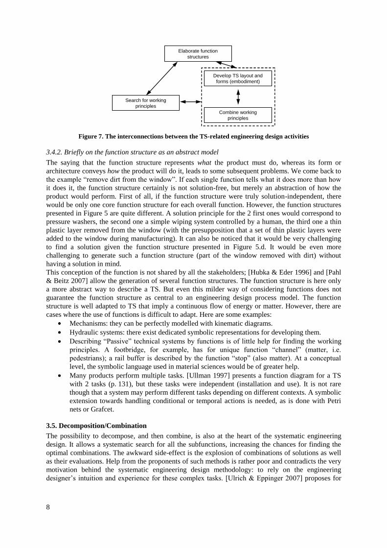
Elaborate function structures
Establish overall function
Search for working principles
Combine working principles
Develop TS layout and forms (embodiment)
E
v
a
l
u
a
t
e
Conceptual design
Embodiment design
Figure 1. Part of the systematic engineering design process model following the TS model
3. Challenging the assumptions behind the systematic engineering design process
models
From the beginning, discussions arose regarding the way these models were set up. They were
presented in a very formal, near-algorithmic way (see e.g. Bender’s historical review [Bender 2004,
chap. 2.1]), suggesting that it would be possible to solve any kind of design problems with a general
procedure. [Franke 1976] showed the theoretical impossibility of such a procedure. 10 years later, a
collection of papers from the workshop ―new impulses for systematic engineering design‖ at the
ICED’85 conference exposed the limitations of such formal processes, triggered among other things
by the fact that these procedures, although taught in nearly all technical universities, were still rarely
used in industry or by practitioners. This really gave an ―impulse‖ to more empirical studies of the
engineering design process, placing the main user of the procedures, i.e. the engineering designer, in
the centre of the investigations. These studies have been ranging from the observations about design
thinking by a single engineering designer up to the area of social interactions and corporate culture.
The early results of the studies of the engineering designer, mainly from the observations of the
design activity modelled as a problem-solving activity, have been rapidly integrated into engineering
design methodologies (already in the 3rd
German edition of [Pahl & Beitz 1993], in [Ehrlenspiel
1995]).
4
The systematic engineering design process models are now presented as helpful to the engineering
designer in case of complex engineering design tasks rather than as a procedure that needs to be
followed in any case: ―All the procedural plans proposed in this book have to be considered as
operational guidelines for action […] In a practical application of these procedural plans, the
operational guidelines for action blend with individual thinking processes. This results in a set of
individual planning, acting and controlling activities based on general procedures, specific problem
situations and individual experiences‖ [Pahl & Beitz 2007, p. 124, emphasis in original].
The core of the procedures present in the literature has not evolved, however; they present mainly the
same characteristics as the first VDI 2221 in 1973 [VDI 1987]: a formalized process model that is
assumed to theoretically, or based on best practices, lead to an optimal product. This is quite at odds
with current research findings, but a first step has been taken towards trying to make a synthesis
between the new findings and the engineering design process models (for example trying to
harmonise the models to the abilities and limitations of the engineering designers), without discarding
them. As mentioned in the introduction, these models are still used as references in the engineering
design research community.
Nevertheless, some criticisms concern the fundamentals of systematic engineering design process
models implying a renewal of these models, especially when the very proponents of systematic
engineering design are those who recommend the strongest deviations from the model they propose.
The main arguments are presented below, and, when applicable, have been selected from the original
works where the models are being presented. The next sections will focus on these areas: continuous
concretisation following the TS model (sections 3.1, 3.2, 3.3), the TS model itself (section 3.4) and
the decomposition/composition principle (section 3.5). A summary is given in section 3.6.
3.1. Continuous concretisation following the TS model
As already pointed out by Franke in 1985 [Franke 1985], this approach involves several problems,
both theoretical and practical.
One difficulty is that there is nearly no one-to-one correspondence between functions, organs
(function carriers) and components —apart from specific types of TS. That is, the choice of an organ
often leads to the addition of a function, which changes the function structure. In the same way, the
choice of the components will change the organ structure, which in turn will change the function
structure. [Franke 1985] shows the necessary iterations with the development of a boiler feed pump
(p. 920).
Figure 2. Functional decomposition of a pump (from [Franke 1985, p. 920])
Moreover, [Malmqvist 1993]’s work shows in a more formal way the inevitable necessity of
iterations. Malmqvist uses a set of generally valid functions and models the organs with the help of
bond graphs, which implies that the organ structure is built solely with the use of physical effects,
without considering the working principles material and geometric characteristics of the working
principles. This follows literally the recommendations of the systematic engineering design
Main function: “increase the pressure” Solution: multi-step centrifugal pump in a synchronised arrangement with radial separated housing and a common shaft