1 A REVIEW OF THE NASA TEXTILE COMPOSITES RESEARCH C. C. Poe, Jr. * , H. B. Dexter * , and I. S. Raju † NASA Langley Research Center Hampton, Virginia 23681-0001 Abstract During the past 15 years NASA has taken the lead role in exploiting the benefits of textile reinforced composite materials for application to aircraft struc- tures. The NASA Advanced Composites Tech- nology (ACT) program was started in 1989 to de- velop composite primary structures for commercial transport airplanes with costs that are competitive with metal structures. As part of this program, sev- eral contractors investigated the cost, weight, and performance attributes of textile reinforced com- posites. Textile composites made using resin transfer molding type processes were evaluated for numerous applications. Methods were also developed to predict resin infiltration and flow in textile preforms and to predict and measure me- chanical properties of the textile composites. This paper describes the salient results of that program. Introduction The NASA Advanced Compopsites Technology program was started in 1989 to develop composite primary structures for commercial transport air- planes with costs that are competitive with those of current metallic airplanes. Textile composites were considered for many components to improve structural performance and to reduce costs. Boe- ing and Lockheed-Martin evaluated textile com- posites for fuselage frames, window belt rein- forcements, and various keel components of the fuselage. Northrop-Grumman evaluated textile concepts for making stiffened skins using 3-D tex- tile composites, and McDonnell Douglas evalu- ated knitted, braided, and stitched textile fabrics for a wing box. The NASA in-house program, in conjunction with university research grants focused on the devel- opment of analytical models to predict resin infiltra- tion and flow in textile preforms, development of a ___________________ * Senior Research Engineer, Mechanics of Materi- als Branch. † Head, Mechanics of Materials Branch, Associate Fellow. Copyright 1997 by the American Institute of Aeronautics and Astronautics, Inc. No copyright is asserted in the United States under Title 17, U. S. Code. The U. S. Government has a royalty- free license to exercise all rights under the copyright claimed herein for Governmental Purposes. All other rights are reserved by the copyright owner. database on damage tolerance and mechanical properties of new material forms, development of analytical models to predict elastic properties and strength of textile reinforced composite materials, and development of test methods for textile com- posites. This papers summarizes the results of the ACT textile composites program. Included are discus- sions on the application of textile composites to primary structural components, mechanics meth- odologies to predict textile material response, test methods to measure material properties, experi- mental methods to measure compaction and per- meability behavior of textile preforms, and analyti- cal methods to predict resin flow in textile pre- forms. Textile Composite Applications Textile material forms that have shown the highest potential for application to composite airframe structures are shown in Fig. 1. Fig. 2 indicates some of the advantages and limitations of each of the textile material forms of interest. Although each of these materials can meet a specific need, the material forms that created the most interest were triaxial braiding for complex structural shapes, multiaxial warp knitting for large area coverage, and stitching for improved damage tolerance. Fuselage Structures During Phases A and B of the NASA ACT program, trade studies were conducted to determine which structural elements could benefit the most from the use of textile composite materials. Fig. 3 shows typical fuselage structural elements that were selected to determine the applicability of tex- tile material preforms and fabrication methods. The structural elements included stiffened side panels, circumferential frames, keel beam frames, and win- dow belts. These structural elements are briefly discussed below. A fuselage side panel with stiffeners and frames is shown in Fig. 4. Using innovative 3-D weaving technology both the frames and the stiffeners are woven with continuous fibers in both directions. Since the weaving process selected can only weave in the 0° and 90° directions, additional ±45° material had to be stitched onto the base fabric to https://ntrs.nasa.gov/search.jsp?R=20040105589 2018-08-29T08:55:15+00:00Z
Transcript
1
A REVIEW OF THE NASA TEXTILE COMPOSITES RESEARCH
C. C. Poe, Jr.*, H. B. Dexter*, and I. S. Raju†
NASA Langley Research CenterHampton, Virginia 23681-0001
Abstract During the past 15 years NASA has taken the leadrole in exploiting the benefits of textile reinforcedcomposite materials for application to aircraft struc-tures. The NASA Advanced Composites Tech-nology (ACT) program was started in 1989 to de-velop composite primary structures for commercialtransport airplanes with costs that are competitivewith metal structures. As part of this program, sev-eral contractors investigated the cost, weight, andperformance attributes of textile reinforced com-posites. Textile composites made using resintransfer molding type processes were evaluatedfor numerous applications. Methods were alsodeveloped to predict resin infiltration and flow intextile preforms and to predict and measure me-chanical properties of the textile composites. Thispaper describes the salient results of that program.
Introduction The NASA Advanced Compopsites Technologyprogram was started in 1989 to develop compositeprimary structures for commercial transport air-planes with costs that are competitive with those ofcurrent metallic airplanes. Textile composites wereconsidered for many components to improvestructural performance and to reduce costs. Boe-ing and Lockheed-Martin evaluated textile com-posites for fuselage frames, window belt rein-forcements, and various keel components of thefuselage. Northrop-Grumman evaluated textileconcepts for making stiffened skins using 3-D tex-tile composites, and McDonnell Douglas evalu-ated knitted, braided, and stitched textile fabricsfor a wing box.
The NASA in-house program, in conjunction withuniversity research grants focused on the devel-opment of analytical models to predict resin infiltra-tion and flow in textile preforms, development of a___________________* Senior Research Engineer, Mechanics of Materi-als Branch.† Head, Mechanics of Materials Branch, AssociateFellow.Copyright 1997 by the American Institute of Aeronautics andAstronautics, Inc. No copyright is asserted in the United Statesunder Title 17, U. S. Code. The U. S. Government has a royalty-free license to exercise all rights under the copyright claimedherein for Governmental Purposes. All other rights are reservedby the copyright owner.
database on damage tolerance and mechanicalproperties of new material forms, development ofanalytical models to predict elastic properties andstrength of textile reinforced composite materials,and development of test methods for textile com-posites.
This papers summarizes the results of the ACTtextile composites program. Included are discus-sions on the application of textile composites toprimary structural components, mechanics meth-odologies to predict textile material response, testmethods to measure material properties, experi-mental methods to measure compaction and per-meability behavior of textile preforms, and analyti-cal methods to predict resin flow in textile pre-forms.
Textile Composite Applications Textile material forms that have shown the highestpotential for application to composite airframestructures are shown in Fig. 1. Fig. 2 indicatessome of the advantages and limitations of each ofthe textile material forms of interest. Althougheach of these materials can meet a specific need,the material forms that created the most interestwere triaxial braiding for complex structural shapes,multiaxial warp knitting for large area coverage, andstitching for improved damage tolerance.
Fuselage Structures During Phases A and B of the NASA ACT program,trade studies were conducted to determine whichstructural elements could benefit the most fromthe use of textile composite materials. Fig. 3shows typical fuselage structural elements thatwere selected to determine the applicability of tex-tile material preforms and fabrication methods. Thestructural elements included stiffened side panels,circumferential frames, keel beam frames, and win-dow belts. These structural elements are brieflydiscussed below.
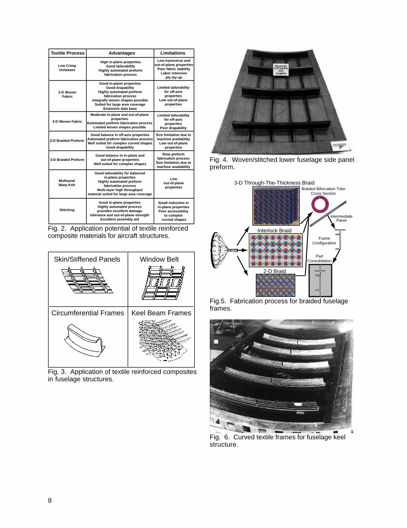
A fuselage side panel with stiffeners and frames isshown in Fig. 4. Using innovative 3-D weavingtechnology both the frames and the stiffeners arewoven with continuous fibers in both directions.Since the weaving process selected can onlyweave in the 0° and 90° directions, additional ±45°material had to be stitched onto the base fabric to
provide the shear load carrying capability. Stitch-ing was performed with Kevlar 29 type thread and aresin film infusion process was used to infiltrate thepreform.
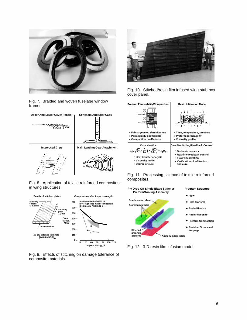
Curved structures with integral flanges can bemade using 2-D triaxial braiding and 3-D through-the-thickness braiding concepts. These braidingconcepts were chosen by Boeing1 and LockheedMartin2 to manufacture circumferential frames. Theflanges of these frames are produced by braidingin pockets or bifurcations that could be folded outprior to resin application as shown in Fig. 5.Matched-metal tooling and resin transfer moldingwere selected to produce composite frames forstructural evaluations.
Thick beams and frames were used near the keelof the fuselage. Design considerations for keelbeam frames are impact damage tolerance,through penetration, damage containment, anddurability. The 2-D triaxial braiding and resin trans-fer molding (RTM) fabrication processes were usedto fabricate the curved frames for structural testing.Several frames that are bonded to a curved hon-eycomb sandwich keel panel are shown in Fig. 6.
Design considerations for the window belt shownin Fig. 3 are out-of-plane interlaminar stresses, sta-bility under combined loads, and damage toler-ance and pressure containment. Design conceptswith through-the-thickness reinforcement wereselected. Both powder coated and RTM fabrica-tion concepts were used. Several woven andbraided fuselage window frames are shown in Fig.7.
Wing Structures Some of the wing structural elements chosen todetermine the applicability of specific textile mate-rial forms and fabrication processes are shown inFig. 8. For wing structures, the design considera-tions are strength, stiffness, impact and discretesource damage. In addition, design should ac-count for joints, access doors, bearing, and open-hole strength, out-of-plane loads, high load intro-duction points, such as landing gear attachments,and lightning strike protection. Through extensivetesting, NASA has determined that through-the-thickness stitching of dry textile preforms is an ef-fective way to achieve improved damage toler-ance. Various factors that can influence the effec-tiveness of stitching such as the stitch type, threadtype, and stitch spacing were studied. Early re-search focus was on improvement of compressionafter impact damage tolerance compared to lami-nated tape composites. Later studies focused onprocessing, manufacturing, and assembly issues.
Fig. 9 presents the compression after impact re-sults on stitched uniweave fabrics, unstitchedprepreg tape, and toughened matrix compositesystems. The results indicate that for an un-stitched brittle composite system, AS4/3501-6,the compression strength drops from 600 MPa toapproximately 140 MPa due to a 68 J impact. Theresults for the toughened matrix composite systemindicates a significant improvement in CAI strengthcompared to the unstitched brittle material, but thetoughened materials are 2 to 3 times more expen-sive. In contrast, the stitched composite demon-strates a significant increase in CAI strength com-pared to the unstitched AS4/3501-6 composite(see the upper curve in Fig. 9). The results ofthese and other tests led McDonnell Douglas toselect through-the-thickness stitching of dry textilepreforms as the baseline for their advanced wingfabrication studies.
Blade stiffeners and integral spar caps were usedas integral stiffening elements for the upper andlower wing covers (see Fig. 8). The stiffeners arefabricated by stacking tubular fabrics and partiallystitching them together to form the vertical(upstanding) blade. The unstitched portion of thetubular fabrics are folded left and right to form thestiffener flanges. The stiffener flanges are stitchedto the wing skin material to form an integral struc-ture that can be infused with resin in one autoclaveoperation. A similar assembly concept is also usedfor the wing box intercostal clips. These clips at-tach rib structure to the wing cover panels. Theintercostal clips need to be designed to transfercompressive crushing and tensile fuel pressureloads. Flanges on the skin side of the clips arefolded and stitched to the wing skin and flanges oneach end of the clips are attached to the bladestiffener webs as shown in Fig. 10. Existingstitching machines only stitch vertically and theintercostal clip to stiffener web attachments requirehorizontal stitching. To perform this operation,alternate attachment concepts are being studied.
Processing Science
Analytical ModelingTo eliminate trial and error processes, analyticalmodels are required to predict resin flow into textilepreforms. The models must be verified throughexperiments if they are to be used with confi-dence. Three-dimensional models are required toadequately capture response of complex preformssuch as wing cover panels that containstitched/knitted fabric skins and stitched/braidedstiffeners. The objectives of the analytical modelsare to predict resin flow and cure as a function of
3
time. The various elements of the NASA proc-essing science program for textile reinforced com-posites are shown in Fig. 11. A 3-D process simu-lation model is being developed under NASAgrant to Virginia Polytechnic Institute.3 Major sub-models include resin flow, heat transfer, and ther-mochemical. A schematic of a 3-D finite elementmodel for infusion of a blade stiffener, includingthe tooling, is shown in Fig. 12. The preform, alu-minum tooling, graphite caul sheet, and resin areincluded in the model.
Textile preforms are complex and permeability de-pends on both the direction of resin flow and thedegree of deformation of the fabric. Since analyti-cal models are not available to predict permeabilityand compaction response of textile preforms, pre-cise experiments must be conducted to acquirecoefficients for use in the analytical models. In ad-dition, cure kinetics of the resin must be charac-terized for input to the analytical models.
Textile Preform CharacterizationExperimental methods have been developed tomeasure fiber volume fraction as a function ofcompaction pressure and permeability as a func-tion of fiber volume fraction. For stitched preforms,compaction and permeability are a function of thestitch density and stitch tension. Fig. 13 showscompaction and permeability data for an unstitchedmultiaxial warp knitted fabric.3 The data shown inFig. 13 indicates that about 175 kPa of pressure isrequired to obtain a 60-percent fiber volume frac-tion and the permeability of the fabric is reduced byabout 50-percent as the fiber volume fraction in-creases from 55-to 65-percent.
Mechanics of Textile Composites Laminates made from unidirectional layers have nofibers in the thickness direction. The layers areusually prepreg tape. On the other hand, textilecomposites are characterized by their 3-D architec-ture. The interlacing yarns of some textiles passcompletely through the textile and give truethrough-the-thickness reinforcement. However,for some textiles, contiguous layers are interlacedby yarns, which do not pass completely throughthe textile but still the interlacing yarns must besevered to separate the layers. Some textile com-posites are made from stacks of fabric and do nothave complete through-the-thickness reinforce-ment. These quasi-laminar textiles are oftentreated using classical lamination theory and some-times referred to as 2-D textiles.
Textiles have periodic geometry that is dictated bythe type of yarns and machines used to make thetextile. A unit cell is the smallest geometric ele-
ment that can be used to represent the periodictextile geometry by spatially translating unit cellswithout rotations or reflections. The field of in-plane normal displacements in the loading direc-tion of a tension coupon is shown in Fig. 14 for atriaxial braid.4 In a triaxial braid, the braider yarns arebraided about fixed (straight) yarns. The fixedyarns in Fig. 14 are perpendicular to the loadingdirection. The unit cell is 11.9 mm long and 5.4mm wide. For uniform displacements (constantstrain), the Moiré lines (fringes) would be straightand equally spaced. Instead, the lines are wavy,and the locations of the yarns are evident in thepattern of waviness. The joggles in the fringes arecaused by intense shearing in regions of highresin content between the surface braider yarns.The rotations (shearing) reverse where the braideryarns cross one another. Normal strain varies in-versely with line spacing. Thus, the normal strainsare highest over the fixed yarns and lowest wherethe braider yarns cross. The average strains inthese two regions differ by a factor of three.
The nonuniform strain field in Fig. 14 raised con-cerns about test methods being adequate tomeasure bulk or average mechanical properties,notched strength, and damage tolerance behaviorof textile composites. This high level of inho-mogeneity guided planning of the program to de-velop a basic mechanics underpinning for the tex-tile composites.
The Mechanics of Textile Composites Programhad the following three objectives: (1) to developtest methods or to modify existing test methods tomeasure mechanical properties and design allow-ables, (2) to develop mechanics models to predictthe properties of the textile composite from theproperties of its constituents and the fiber architec-ture, and (3) to develop a coupon-type test database for textile composites.5 Results of each ofthe investigations are briefly reviewed below.
Test MethodsA survey of commonly used test methods to derivedesign allowables for laminated prepreg tape com-posites was undertaken by Masters and Por-tanova.6 The objective of this survey was to de-termine the minimum test methods that should beevaluated for textile composites. The test meth-ods in Fig. 15 were evaluated by conducting testson various textiles. The best of the test methodsare also given in Fig. 15. They were determinedon the basis of low coefficient of variability, appro-priate failure mode, and simplicity. None of theinplane shear test methods was found to be satis-factory to measure strength. Some other inter-laminar test methods were evaluated for tension,
4
compression, shear, and fracture toughness.7
Some gave reasonable results for the quasi-laminar textiles, but most were difficult to conductor gave unacceptable results for the 3-D textiles.
Because of the potential for a very nonho-mogeneous strain field as shown in Fig. 14, astudy was made to determine the effect of straingage size on strain measurements. The ratio ofmodulus from strain gages to that from extensome-ters is plotted against the ratio of strain gage lengthto unit cell length in Fig. 16. The modulus is for theloading direction. The gage length for the exten-someter was 25 mm, and the strain gage sizesranged from 3.2 by 1.6 mm to 12.7 by 12.7 mm.Measurements were made on four triaxial braidedcomposites. The difference between strain gagesand extensometer decreased with strain gagelength. For strain gages longer than the unit cell,the difference was +4 to -6%.
Net tension strengths are plotted in Fig. 17 for twotriaxial braids and two equivalent tape laminates.8
Some coupons contained 2.5-cm-diameter holesand some contained no holes. The braid angleand fraction of fixed (axial) yarns was 70° and 46%,respectively, for both braids. However, the yarnsused in making LLL contained 2.5 times as manyfilaments as those used in making SLL. (The nota-tion [030k/±706k] in Fig. 17 indicates 30k fixed yarnsand 6k braider yarns.) The areal weights of the 0°and ±70° plies in the equivalent laminates wereapproximately equal to those of the fixed andbraider yarns, respectively, in the braids. The plieswere also thicker in the LLL equivalent tape lami-nate than the SLL laminate to simulate the largeryarns in the braid. The unnotched strength of theSLL and LLL braids were 11% and 33% less, re-spectively, than those of the equivalent tape lami-nates. On the other hand, the open-holestrengths of the SLL and LLL braids were only 2%and 12% less, respectively, than those of theequivalent tape laminates. The strength reduc-tions were due to the yarn crimp introduced by in-terlacing in the braiding process. The reductionswere greater for the LLL braids than the SLL braidsdue to the larger crimp associated with the largeryarns. The strengths of the LLL equivalent tapelaminates were about the same as those of theSLL equivalent tape laminates. Stiffness of theSLL and LLL braids were reduced much less bycrimp than the unnotched strengths. The modu-lus of the LLL braid was about 92% of that pre-dicted for the tape laminate, and the modulus ofthe SLL braid was about 100% of that predicted forthe tape laminate.
Radiographs of specimens like those in Fig. 17with open holes are shown in Fig. 18. The speci-mens were loaded to approximately 75% of theirultimate load before x-raying, and then an x-rayopaque dye penetrant was applied to the compos-ites to better reveal the damage. Cracking patternsin the matrix were similar for the braids and equiva-lent tape laminates. The cracks were deeper andmore intense in radiographs of the compositeswith thicker plies and larger yarns.
Similar results were also obtained by Boeing fortriaxial braids and equivalent tape laminates.9 Thetest methods included• unnotched tension, compression, and shear• open-hole tension and compression• filled-hole tension• bolt bearingThe specimens were loaded both parallel and per-pendicular to the fixed yarns.
Through-the-thickness strengths are plotted inFig. 19 for tape laminates and quasi-laminar 2-Dtextiles.10 The bars represent mean values, and thetick marks below and above the bars represent ex-treme values. The strengths were calculated frombend tests. These 2-D textiles failed in the bendregions from circumferential (interlaminar) cracksmuch as the tape laminates. The strengths for the2-D textiles and the 48-ply AS4/3501-6 tape lami-nates were the lowest, those for the AS4/8551-7toughened tape laminates were intermediate, andthose for the 24-ply AS4/3501-6 tape laminateswere the highest. Strengths for the 24-plyAS4/3501-6 tape laminates were high probablybecause of large fiber volume fractions. Fiber vol-ume fractions for the 24-ply AS4/3501-6 tapelaminates were about 62%, and those for the othercomposites ranged from 50% to 55%. Thus, tak-ing into account fiber volume fraction, resin tough-ness had more influence on through-the-thickness strength than the 3-D nature of the lay-ers.
3-D weaves were also tested, but radial cracks de-veloped in the bend region, making strength cal-culations suspect.10 However, when all the com-posites were ranked according to bending mo-ment at failure normalized by width and thickness,the 3-D weaves were the lowest.
For low impacter velocities (no viscoelastic behav-ior) and large impacter masses (relative to targetmass), impact behavior is quasi-static.11 Thus, astatic indentation (SI) test can be used to measurea composite’s damage resistance. (The static in-dentation test is currently being considered by theAmerican Society for Testing and Materials (ASTM)
5
for a standard test method.) The contact force isplotted against indenter displacement in Fig. 20 fora non-stitched and stitched 16-ply AS4/3501-6quasi-isotropic composite plate. The layers wereuniweave fabric. The composite plate wasclamped between two metal plates with concentriccircular openings. The indenter was mounted in auniversal testing machine. The discontinuities inthe curve are caused by the development andspread of damage. The first indication of damageis labeled F1. The specimen was unloaded afterwidespread damage but before penetration. Onemajor advantage of the SI test is that the impactforce and state of damage can be controlled. Also,the impact energy for an equivalent drop weighttest can be calculated by integrating the force dis-placement curve. This procedure was used byPortanova to determine drop weight energies toproduce specific dent depths, ranging from barelyvisible to readily visible.12
Delamination diameter is plotted against impactforce for single and multiple SI tests in Fig. 21.13
The delamination diameters were calculated for acircle equal in area to the overall extent of damagemeasured on C-scan images. These quasi-isotropic, uniweave composites were not stitched.In a single test, the specimen is only loaded andultrasonically scanned once; but, in multiple tests,the specimen is loaded and scanned more thanonce with the maximum load increasing on eachsuccessive loading. The results in Fig. 21 for sin-gle and multiple tests are in agreement, indicatingthat multiple tests can be used to greatly reducethe number of specimens for a given number oftests. For impact forces between F1 and penetra-tion, the damage diameter increases in proportionto impact force. The slope corresponds to 1/π Q*,where Q* is a critical value of transverse shearstrength per unit length. Thus, F1 and Q* can beused as metrics for damage resistance.
Values of F1 and Q* are plotted in Figs. 22 and 23for tape laminates and textile composites.13 SItests were made with a 1.3-mm-diameter hemi-spherical indenter, and all of the composites had anominal thickness of 6.3 mm. Values of F1 for the2-D braids and 3-D weaves were somewhat smallerthan those for the uniweaves and tape laminates, 4to 7 kN compared to 8 to 10 kN, respectively. Val-ues of Q* were about 100% greater for theIM7/8551-7 tape, the stitched uniweave, and theOS2 3-D weave than the other tapes and textiles.Thus, the stitching and 3-D architecture of OS2were equivalent to the toughened 8551-7 epoxy.
The LS and TS weaves were layer-to-layer andthrough-the-thickness angle interlocks, respec-
tively. The weaver yarns of the orthogonal inter-lock (OS) weaves also passed through the thick-ness but were perpendicular to the weaving plane,much like stitching. The warp, weft, and weaveryarns of the OS1, LS1, and TS1 weaves had twiceas many filaments as those of the OS2, LS2, andTS2 weaves. Therefore, 3-D architecture alonewas not sufficient to assure improved impact dam-age resistance.
Impact force is plotted against thickness in Fig. 24for stitched and nonstitched uniweaves for threelevels of damage.14 Logarithmic scales were usedfor convenience. The levels of damage were non-visible damage (Fi), barely visible damage (0.13-mm dent), and visible damage (2.5-mm dent).Thicknesses ranged from 16 to 48 plies. In allcases, the impact force increased approximatelywith thickness to the 3/2 power. The effect of thestitching on impact force changed with level ofdamage - a negative effect for nonvisible damageand a positive effect for visible damage.
Damage resistance Q* is plotted against thicknessin Fig. 25 for stitched and nonstitched uniweaves.For the thinnest coupons, the stitching gave littlebenefit, but the benefit increased dramatically withthickness.
Post-impact tension and compression strengthsare plotted in Fig. 26 for visible impact damage.15
Impacts were made using 5.4-kg falling weightswith a 13-mm-diameter hemispherical indenter.Visible impact damage was represented by 2.5-mmdents. SI tests were used to determine fallingweight energies to produce the dents. Thestrengths were normalized by undamagedstrengths for convenience. For the braids and 3-Dweaves, tension strength ratios were generallygreater than compression strength ratios. For theuniweave textiles, however, tension strength ra-tios were less than compression strength ratiosespecially for the stitched uniweave. Strength ra-tios were least for the nonstitched uniweaves.Stitching improved the compression strength ratiofar more than the tension strength ratio.
The current test methods for post-impact strengthdo not account for boundary effects and were notconsidered acceptable for developing allowablesfor specific impact energies.7 The boundaries af-fect the impact problem in the following two primaryways: (1) the size of damage resulting from a givenkinetic energy and mass and (2) the residualstrength for a given damage size. Most of the ef-fect on damage size can be eliminated by using adetectable damage metric such as dent depthrather than a specific impact energy. However, for
6
detectable dents, damage size can be relativelylarge compared to coupon size; and, without finitewidth correction factors, coupon strengths can beunrealistically low. For example, the test sectionsof the specimens in Fig. 26 were 10 by 10 cm, andthe damage sizes in C-scans ranged from 4.8 cm to6.8 cm.12 If the impact damage was equivalent toan open hole in a finite width sheet of infinitelength, the strengths should have been correctedby factors ranging from 1.5 to 2.3, respectively.The C-scan damage sizes indicate size of matrixdamage. Because fiber damage is much smaller insize than matrix damage, the compressionstrengths in Fig. 26 may have been unduly lessthan tension strengths due to the use of smallcoupons.
Analytical ModelsCox and Flanagan compiled a handbook of ana-lytical methods for textile composites.16 In thishandbook they discussed the choice of textile andtape laminates, failure mechanisms, variousmathematical concepts and associated computercodes for predicting elastic constants and thermalexpansion coefficients, and strength predictions.The capabilities of the computer codes are given inFig. 27.
The SAWC computer code in Fig. 27 computesstresses and initiation and progression of damagein plain weave textiles. A single unit cell is mod-eled using finite elements. A stress-strain curvecalculated using this code is shown in Fig. 28 for aAS4/3501-6 plain weave composite.5 The initialfailure is at point “a” where the stress σ 22 in the filltow exceeds its allowable. (The fill tow is orientedtransverse to the applied load.) At point b, thedamage due to σ 22 spreads; and, at point c, theresin in the warp yarn fails where σ 33 and σ 13stresses exceed their allowables. The large dropin load is caused by the large crimp angle, analo-gous to a unidirectional tape laminate loaded off-axis. With a smaller crimp angle, the load dropwould have been smaller, and loading could havecontinued until the fibers in the warp tows fail.
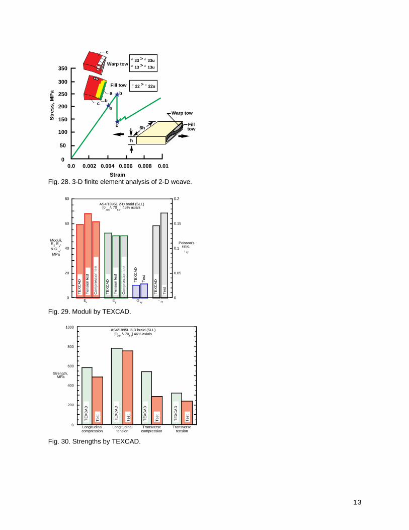
The TEXCAD computer code in Fig. 27 can beexecuted on a PC or Macintosh type desktopcomputer. This code does not use finite elementsbut assumes uniform strain throughout the unit celland superimposes strains due to flexure of thecrimped yarns. Weaves and braids can be ana-lyzed using TEXCAD. Graphs of moduli andstrength from experiments and TEXCAD are com-pared in Figs. 29 and 30 for one of the triaxialbraids. The predictions and experiments are ingood agreement. In general, agreement was bet-ter for moduli than strength.
Coupon-Type Data Base A coupon-type data base was compiled from theresults generated by the ACT program.17 The datadocumentation for this data base satisfies the re-quirements laid out in the MIL-HDBK-17. The fol-lowing properties are included: elastic moduli; un-notched, open-hole, filled-hole, tension and com-pression strengths for uniaxial loads; unnotchedtension and compression strengths for biaxialloads; and bearing strengths. The following mate-rials are represented: 2-D triaxial braids, 3-D mul-tiaxial braids, stitched uniweave, 8-harness and 3-D interlock weaves, stitched multi-axial warp knits,and uniweaves. This data base is available in thefollowing two formats: a summary or executive ver-sion in Microsoft Excel for Apple Macintosh
Series and Windows Series operating systemsand an unabridged version in MSC/MVISION forUNIX Series operating systems. These are avail-able at URLhttp://techreports.larc.nasa.gov/ltrs/96/NASA-96-cr4747.refer.html.
Concluding Remarks Textile reinforced composites and their applicationpotentials to aircraft primary structure are beingexplored in the NASA Advanced CompositesTechnology Program (ACT). Structural elements,which are part of the primary structure, include fu-selage stiffened panels, frames, and window belts,and wing upper and lower covers, stiffener andspar caps, intercostal clips, and landing gear at-tachments. Some of the structural elements arestitched to improve damage tolerance. Either resintransfer molding or resin film infusion processesare used to impregnate the preforms. Analyticalmodels are under development to predict resinflow and cure of textile reinforced composites.The developments in stitching, weaving and knit-ting have lead to composite structures that are du-rable and damage tolerant, light-weight, and cost-effective.
NASA in-house research, with the help of univer-sity research grants, has developed a basic me-chanics underpinning of textile composites.These studies led to the development of (1) testmethods for measuring material properties anddesign allowables, (2) mechanics models to predictthe effects of fiber preform architecture and con-stituent properties on engineering moduli, stiff-ness, strength, damage resistance, and fatiguelife, and (3) an electronic data base of coupon typetest data.
References
7
1Ilcewicz, L. B., Smith, P. J., Walker, T. H., andJohnson, R. W., “Advanced Technology Commer-cial Fuselage Structure,” Proceedings of the FirstNASA ACT Conference, NASA CP-3104, Part 1,1991, pp. 127-155.
2Jackson, Anthony C., Barrie, Ronald E., andChu, Robert L., “Textile Composite FuselageStructures Development,” Proceedings of theThird NASA ACT Conference, NASA CP-3178,Part 1, 1992, pp. 79-96.
3Loos, A. C., MacRae, John D., Kranbuehl, DavidE., Husmann, Christopher H., Rohwer, Kim, andDeaton, Jerry W., “Resin Film Infusion (RFI) Proc-ess Simulation of Complex Wing Structures,” Pro-ceedings of the Fifth NASA/DoD Advanced Com-posites Technology Conference, NASA CP-3294,May 1995, pp. 811-833.
4Masters, John E., “Strain Gage Selection Crite-ria for Textile Composite Materials,” NASA CR-198286, Feb. 1996.
5Poe, Jr., C. C., and Harris, C. E., “MechanicsMethodology for Textile Preform Composite Mate-rials,” Proceedings of the Sixth NASA DoD Ad-vanced Composites Technology Conference,NASA CP-3326, Part 1, 1996, pp. 95-130.
6Masters, John E., and Portanova, Marc A.,“Standard Test Methods for Textile Composites,”NASA CR-4751, Sept. 1996 (available at URLhttp://techreports.larc.nasa.gov/ltrs).
7Poe, C. C., Jr., “Mechanics methodology fortextile preform composite materials,” Proceedingsof the 28th International SAMPE Technical Con-ference, Nov. 1996, pp. 324-338.
8Norman, Timothy L., Anglin, Colin, Gaskin,David, and Patrick, Mike, “Effect of Open Hole onTensile Failure Properties of 2D Triaxial BraidedTextile Composites and Tape Equivalents,” NASACR-4676, June 1995.
9Minguet, Pierre J., and Gunther, Christian K., “AComparison of Graphite/Epoxy Tape Laminatesand 2-D Braided Composites Mechanical Proper-ties,” NASA CR-4610, July, 1994.
10Jackson, Wade C. and Ifju, Peter, G., “Through-the-Thickness Tensile Strength of Textile Com-posites,” Composite Materials: Testing and De-sign (Twelfth Volume), ASTM STP 1274, R. B.Deo and C. R. Saff, Eds., American Society forTesting and Materials, 1996, pp. 218-238.
11Jackson, W. C., and Poe, Jr., C. C., “The Use ofImpact Force as a Scale Parameter for the ImpactResponse of Composite Laminates,” Journal ofComposites Technology Research, Vol. 15 (No.4), Winter 1993, pp. 282-289.
12Portanova, M. A., “Evaluation of the Impact Re-sponse of Textile Composites,” NASA CR-198265, Dec. 1995.
13Jackson, Wade C., and Portanova, Marc A.,“Impact Damage Resistance of Textile Compos-
ites,” Proceedings of the 28th InternationalSAMPE Technical Conference, Nov. 1996, pp.339-350.
14Poe, Jr. C. C., “Residual Strength of Compos-ite Aircraft Structures with Damage,” ASM Hand-book, Vol. 19, Fatigue and Fracture, 1996, pp.920-935.
15Portanova, M. A., “Impact Damage Tolerance ofTextile Composites,” Proceedings of the 28th In-ternational SAMPE Technical Conference, Nov.1996, pp. 351-362.
16Cox, Brian N., and Flanagan, Gerry, “Handbookof Analytical Methods for Textile Composites,”NASA CR-4750, 1997 (available at URLhttp://techreports.larc.nasa.gov/ltrs).
17Delbrey, Jerry, “Database of Mechanical Prop-erties of Textile Composites,” NASA CR-4747,Aug. 1996 (available at URLhttp://techreports.larc.nasa.gov/ltrs).
Multiaxial warp knit (stitched & unstitched)
3-D braid Knitted/stitched
2-D triaxial braid (stitched & unstitched)
Fig. 1. Textile material forms evaluated.
8
Multiaxial Warp Knit
Stitching
Good in-plane properties Highly automated process provides excellent damage
tolerance and out-of-plane strength Excellent assembly aid
Low out-of-plane properties
Small reduction in in-plane properties Poor accessibility
to complex curved shapes
Good tailorability for balanced in-plane properties
Highly automated preform fabrication process
Multi-layer high throughput material suited for large area coverage
3-D Woven Fabric
2-D Braided Preform
3-D Braided Preform
Limited tailorability for off-axis properties
Poor drapability
Size limitation due to machine availability
Low out-of-plane properties
Slow preform fabrication process
Size limitation due to machine availability
Moderate in-plane and out-of-plane properties
Automated preform fabrication process Limited woven shapes possible
Good balance in off-axis properties Automated preform fabrication process Well suited for complex curved shapes
Good drapability
Good balance in in-plane and out-of-plane properties
Well suited for complex shapes
Textile Process Advantages Limitations
Low Crimp Uniweave
2-D Woven Fabric
Good in-plane properties Good drapability
Highly automated preform fabrication process
Integrally woven shapes possible Suited for large area coverage
Extensive data base
Low transverse and out-of-plane properties
Poor fabric stability Labor intensive
ply lay-up
Limited tailorability for off-axis properties
Low out-of-plane properties
High in-plane properties Good tailorability
Highly automated preform fabrication process
Fig. 2. Application potential of textile reinforcedcomposite materials for aircraft structures.
Skin/Stiffened Panels
Circumferential Frames
Window Belt
Keel Beam Frames
Fig. 3. Application of textile reinforced compositesin fuselage structures.
Fig. 4. Woven/stitched lower fuselage side panelpreform.
3-D Through-The-Thickness Braid
Interlock Braid
2-D Braid
Braided Bifurcation Tube Cross Section
Intermediate Panel
Frame Configuration
Part Consolidation
Fig.5. Fabrication process for braided fuselageframes.
Fig. 6. Curved textile frames for fuselage keelstructure.
9
Fig. 7. Braided and woven fuselage windowframes.
Upper And Lower Cover Panels
Intercostal Clips Main Landing Gear Attachment
Stiffeners And Spar Caps
Fig. 8. Application of textile reinforced compositesin wing structures.
700
600
500
400
300
200
100
00 20 40 60 80 100 120
Impact energy, J
Comp. stress,
MPa
A
B
C
Compression after impact strength
Stitching spaced at 3.2 mm
Stitching pitch 3.2 mm
Load direction
Details of stitched plates
48 ply stitched laminate [+45/0/-45/90] 6s
A = Unstitched AS4/3501-6 B = Toughened matrix composites C = Stitched AS4/3501-6
Fig. 9. Effects of stitching on damage tolerance ofcomposite materials.
Fig. 10. Stitched/resin film infused wing stub boxcover panel.