SAND88-3005 * TIC-0879 ?? UC-71 Unlimited Release Printed December 1988 A Review of the Safety Features of 6Ml Packagings for DOE Programs US Departmwt of Energy Prepared by Sandia Nalional Laboralories Albuquerque. New Mexico 87165 and Livermore. California 94660 for the United Slates Oeparlmenl of Energy under Contract DE-AC04-76DPD0789
Transcript
SAND88-3005 * TIC-0879 ?? UC-71Unlimited ReleasePrinted December 1988
A Review of the Safety Features of6Ml Packagings for DOE Programs
US Departmwt of Energy
Prepared bySandia Nalional LaboraloriesAlbuquerque. New Mexico 87165 and Livermore. California 94660for the United Slates Oeparlmenl of Energyunder Contract DE-AC04-76DPD0789
I’rintrd in the Ilnitcd States of AmericaAVilililtJtC fromN;II ional ‘I’echnical Inl’ormat ion Sc1rvic.eI1.S. I Iepartnient of (‘0mmcrrP~~2X!) t’orl I<~~val I~o;rd,Slll 111”11f~1d \>A :!“lrilh
US DEPARTMENT OF ENERGYSpecification-6M Safety Task Force
September 26, 1988
ABSTRACT
This report compiles and summarizesthe extant documentation on Department of Transportation
Specification-6M packagings used to supportDepartment of Energy programs.
*This work performed at Sandia National Laboratories, Albuquerque, NewMexico, supported by the U.S. Department of Energy under Contract DE-AC04-76DP00789
ACKNOWLEDGMENTS
The authors of this report would like to express their gratitude to themembers of the DOE Specification 6M Safety Task Force for their help ingathering the available information on DOT Specification 6M packagings andsupplying other valuable information on the use of these packagings insupport of Department of Energy programs.
,
1.11.21.31.41.5
2.0
2.12.22.32.42.52.62.72.82.92.10
2.112.122.13
3.0
3.13.23.33.4
3.53.6
3.73.8
4.0
4.1. 4.2
4.3.
A REVIEW OF THE SAFETY FEATURES OF 6M PACKAGINGS FOR DOE PROGRAMS
TABLE OF CONTENTS
Preface
GENERAL INFOt(iQxTION
Description of 6M PackagingsCharacteristics of Outer DrumCharacteristics of Insulating Disks and RingsCharacteristics of DOT-2R Containment VesselSummary of 6M Packaging Regulatory Tests and Analysis
STRUCTURAL EVALUATION
General Standards for All PackagesGeneral Requirements for Normal Conditions of Transport - IGeneral Requirements for Normal Conditions of Transport - IIGeneral Requirements for Normal Conditions of Transport - IIIGeneral Requirements for Normal Conditions of Transport - IVRequirements for Hypothetical Accident ConditionsResults of Accident Condition Tests - Free DropResults of Accident Condition Tests - PunctureResults of Accident Condition Tests - ThermalResults of Accident Condition Tests - Transient ThermalAnalysisResults of Accident Condition Tests - Thermal StressesLoad Resistance of the 6M PackagingResults of Accident Condition Tests - Immersion
THERMAL EVALUATION
Thermal Properties of 6M Packaging MaterialsThermal Analysis MethodologyThermal Analysis for Normal Conditions - Package TemperaturesThermal Analysis for Ncrmal Conditions - Package InternalPressuresThermal Analysis for Normal Conditions - Thermal StressesThermal Analysis for Accident Conditions - PackageTemperaturesThermal Testing for Accident ConditionsThermal Analysis for Transport Accident Conditions - PackageInternal Pressures
CONTAINMENT
Types of Radioactive Materials Authorized for 6M PackagingsDesign and Performance of Primary and Secondary ContainmentSystemPerformance Under Normal Conditions of Transport
Use of 6M for Shipment of Fissile MaterialTabulated Values of Fissile Class I and Class II LimitsBasis for Tabulated Loading Values
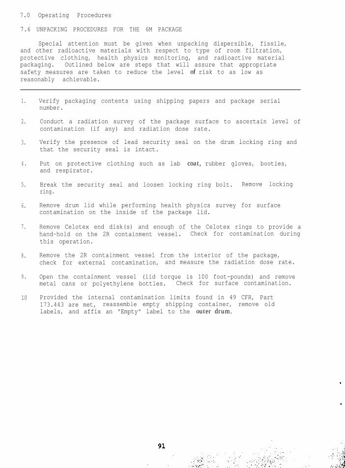
OPERATING PROCEDURES
Operating Procedures for 6M PackagingsGeneral Specifications and Requirements for PlutoniumPackagings.Packaging of Plutonium Material in Food Pack CansLoading of the 2R Containment VesselFinal Assembly of the 6M PackageUnpacking Procedures for the 6M Package
ACCEPTANCE TESTS AND MAINTENANCE PROGRAM
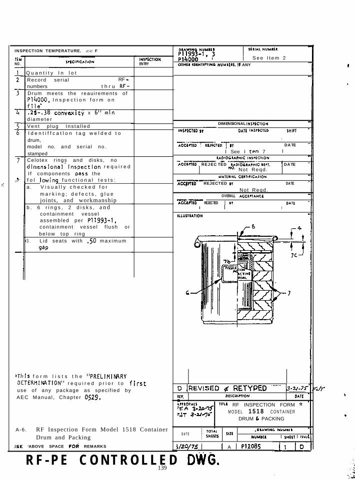
Inspection Prior to First Use of the Packaging
QUALITY ASSURANCE
Structure and Function of the Quality Assurance ProgramQuality Assurance Program for 6M PackagingsQuality Assurance AssessmentDesign ControlProcurement Document ControlInstructions, Procedures, and DrawingsDocument ControlControl of Purchased Materials, Equipment, and ServiceIdentification and Control of Materials, Parts, and ComponentsControl of Special ProcessesInspection ControlRequired Test ControlControl of Measuring and Test EquipmentHandling, Storage, and ShippingInspection, Test, and Operating StatusControl of Nonconforming Materials, Parts, or Components
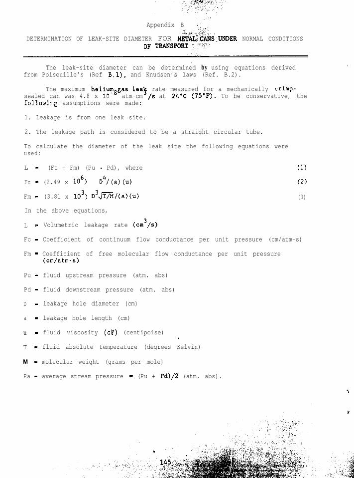
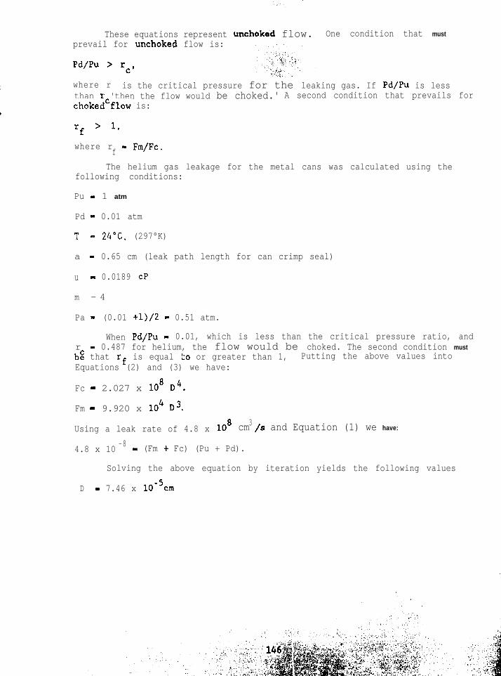
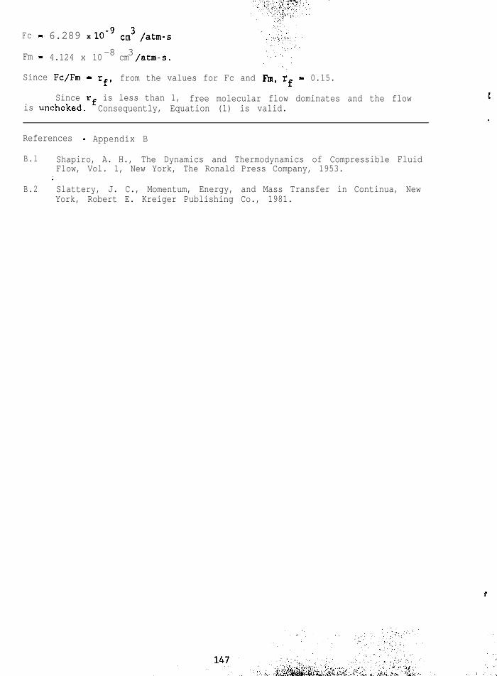
Appendix B Determination of Leak Site Diameter for Metal Cans UnderNormal Conditions of Transport
Appendix C ue~.-~~,,i;;~;ti~n nf Air Leak Rate Under Normal Conditions ofTransport
127129131
133
145
148
P-l
1.1.
1.2.1
1.2.2
1.. 3. 1
1.3.2
1.4.1
2.5.1
2.9.1
2.9.2
2.10.1
3.1.1
3.1.2
3.1.3
3.3.1
LIST OF FIGURES
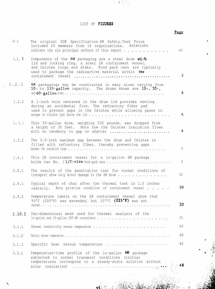
The original DOE Specification-6M Safety.Task Forceincluded 29 members from i6 organizations. Asterisksindicate the six principal authors of this report . . . . . . . . . . . .
Components of the 6M packaging are a steel drum wi.-hlid and locking ring, a steel 2R containment vessel,and Celotex rings and disks. Food pack cans are typicallyused to package the radioactive material within thecontainment vessel ,.......,........,.........................
6M packagings may be constructed in many sizes varying fromlo- to IlO-gallon capacity. The drums shown are lo-, 30-,and 60-gallon sizes . . . . . . . . . . . . . . . . . . . . . . . . . . . . . . . . . . . . . . . . . .
A l-inch hole centered in the drum lid provides ventingduring an accidental fire. The refractory fiber padused to prevent gaps in the Celotex while allowing gases toescape is visible just below the lid . . . . . . . . . . . . . . . . . . . . . . . . .
This 55-gallon drum, weighing 535 pounds, was dropped froma height of 30 feet. Note how the Celotex insulation flowswith no tendency to gap or shatter ..,.....,..................
The 0.5-inch maximum gap between the drum and Celotex isfilled with refractory fiber, thereby preventing gapsbetween the insulation rings . . . . . . . . . . . . . . . . . . . . . . . . . . . . . . . . .
This 2R containment vessel for a lo-gallon 6M packageholds two No. 2 l/2-size food pack cans . . . . . . . . . . . . . . . . . . . . . .
The results of the penetration test for normal conditions oftransport show only minor damage to the 6M drum . . . . . . . . . . . . . .
Typical depth of char after the thermal test is 1.5 inchesradially. Note pristine condition of containment vessel . . . . .
Temperature-time profile of the lo-gallon 6M packagesubjected to normal transport conditions (initialtemperatures correspond to a steady-state solution withoutsolar insolation) . . . . . . . . . . . . . . . . . . . . . . . . . . . . . . . . . . . . . . . . . ..o. :.
xi
6
8
22
32
40
40
40
3.3.2.
t
3.7.1
4.2.1
4.2.2
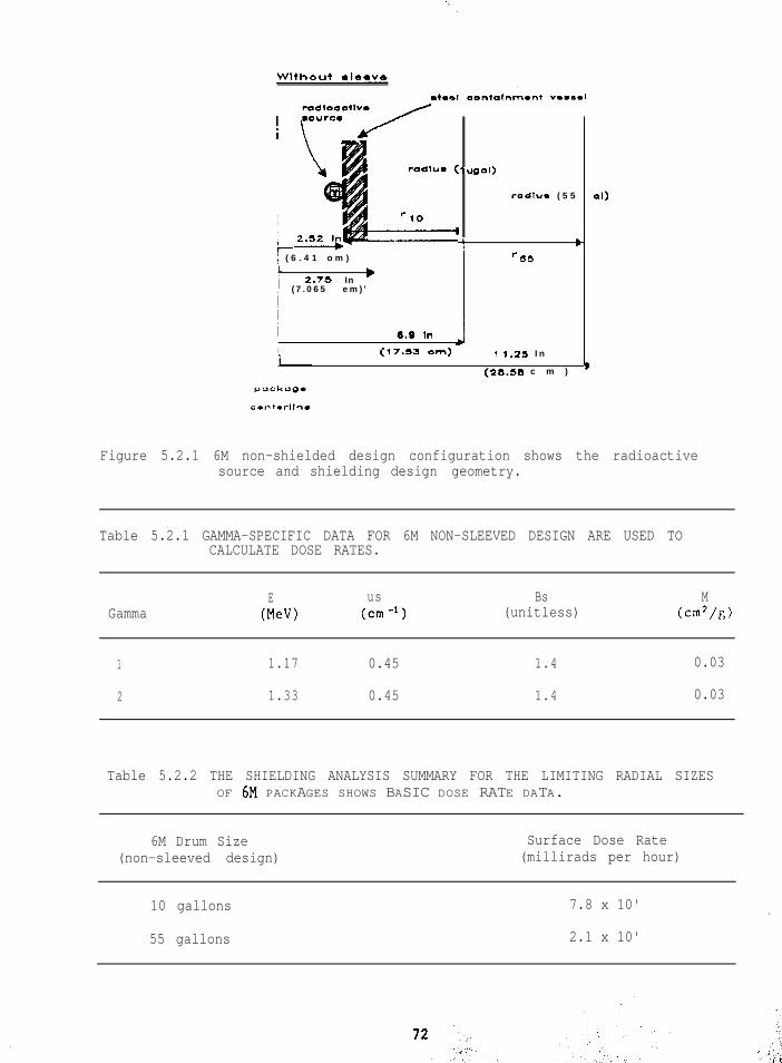
5.2.1
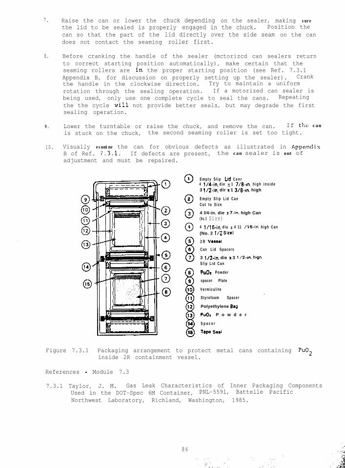
7.4.2
A-l.
A-2.
A-3.
A-4.
A-5.
, A-6.
. A-7.
LIST OF FIGUREI (Continued)
Temperature-time profile of the 55-gallon 6M packagesubjected to normal transport conditions (initialtemperatures correspond to a steady-state solution withoutsolar insolation) . . . . . ..~....~...............,..,............
Time-temperature data recorded from thermocouple stationsduring thermal test runs (Ref. 3.7.2) on a 30-gallon 6Mshow the 2R containment vessel is not over-heated . . . . . . . . . . . .
Both of the typical 2R containment configurationsprovide for positive sealing during normal and accidentconditions of transport . . . . . . . . . . . . . . . . . . . . . . . . . . . . . . . . . . . . . .
6.2.1 The Fissile Class I and Class II loading limitsare tabulated as shown for the metal form, alloys, andcompounds of uranium and plutonium ..*...............*.........
This report, prepared by a U.S. Department of Energy (DOE) Task %orceand organized for clarity into two-page modules, argues that the U.S.Department of Transportation (DOT) Specification-6M packagings (hereafterreferred to as 6M packaging, or simply 6M) merit continued DOE use and, ifnecessary, DOE certification.
This report is designed to address the specific requirements of aSrlfety Analysis Report for Packaging (SARP). While not a SARP, this reportci.rlstitutes a compilation 'of all available documentation on 6M packagings.'Tile authors individually, and the Task Force collectively, believe theirirlvestigation provides justification for the continued use of 6M packagingshccnuse they meet criteria fcr quality assurance and for safety under normaland accident conditions as defined by the U.S. Nuclear Regulatory Commission(NRC) regulations. This report may be used by DOE managers to assist intlc1il)eration.s on frlturc requirements for 6M packagings as they are requiredto :;upport DUE rr3grams.
For ;:le purpose of ready evaluation, th'.s report includes categoricaltop its found in Nuclear Regulatory Guide 7.9, the topical guideline forSARI's. The format, however, will (it is hoper:! pleasantly surprisecustom*~ry reader expectatiolls. For, whila maintaining categorical headingsand subheadings found in SARPs as a skeleton, the Task Force chose to Edoptthe doc&ment design principles developed by Hughes Aircraft in the 19hOs,"St?quential Thematic Organization of Publications" (STOP). The STOP formatdivides t5e document into one or two-page modules or themes. Turning thepnp,e means changing the topic or seeing a new self-contained facet of thesnme topic. Each thematic module begins, after stating a categoricalsection heading, with a capitalized topic heading followed by an underlinedr;cnt.cnce stating the main point or contention of the module. Figures, if;Iny, occur on the right-hand page and relate specifically to the text.f’roduction of this report according to STOP principles is a DOE pilotproject; the authors will appreciate comments on its readability.
DOT Specification-6M packagings for the shipment of radioactivemntcrials (my) are built according to the rules set forth in DOTreguI.ati.ons in Title 49, Code of Federal Regulations (WI'.), Part 178.104.The 6M ranges in size from 10 to 110 gallons (the size of the cuter metaldrum) . These 6Ms have been safely, reliably, and economically used for morethan 20 years to transport RAM among DOE laboratories and elements of theDOE production complex. Predictably, 6M packages have suffered accidents ofvarying severity; however, they have no record of ever having leaked.
The DOE chose to begin compiling all available information toslrbstantiate the adequacy of 6Md when it was learned in 1983 the D3T mightreplace 49 CFR 178.104 with regulations eliminating specification packagesfor shipping Type B quantities of RAM. The new regulations might requireinstead that each packaging be separately certified either by the NRC forits licensees or by the DOE for use in its shipments.
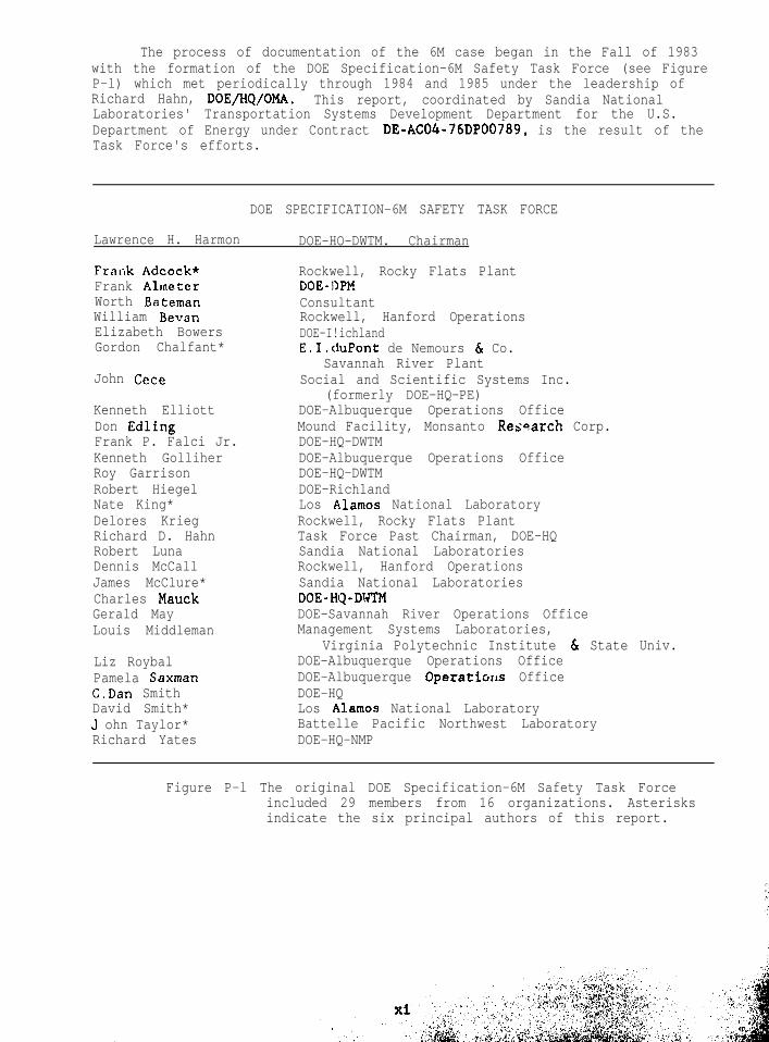
The process of documentation of the 6M case began in the Fall of 1983with the formation of the DOE Specification-6M Safety Task Force (see FigureP-l) which met periodically through 1984 and 1985 under the leadership ofRichard Hahn, DOE/HQ/OMA. This report, coordinated by Sandia NationalLaboratories' Transportation Systems Development Department for the U.S.Department of Energy under Contract DE-hC04-76DP00789, is the result of theTask Force's efforts.
Rockwell, Rocky Flats PlantDOE-DPMConsultantRockwell, Hanford OperationsDOE-I!ichlandE.I.tluPont de Nemours & Co.
Savannah River PlantSocial and Scientific Systems Inc.
(formerly DOE-HQ-PE)DOE-Albuquerque Operations OfficeMound Facility, Monsanto Research Corp.DOE-HQ-DWTMDOE-Albuquerque Operations OfficeDOE-HQ-DWTMDOE-RichlandLos Alamos National LaboratoryRockwell, Rocky Flats PlantTask Force Past Chairman, DOE-HQSandia National LaboratoriesRockwell, Hanford OperationsSandia National LaboratoriesDOE-HQ-DVTMDOE-Savannah River Operations OfficeManagement Systems Laboratories,
Virginia Polytechnic Institute 6 State Univ.DOE-Albuquerque Operations OfficeDOE-Albuquerque Operatiorls OfficeDOE-HQLos Alamos National LaboratoryBattelle Pacific Northwest LaboratoryDOE-HQ-NMP
Figure P-l The original DOE Specification-6M Safety Task Forceincluded 29 members from 16 organizations. Asterisksindicate the six principal authors of this report.
.
”
.,. ,,
1.0 General Information
1.1 DESCRIPTION 3F 6M PACKAGINGS
DOT Specification 6M packagings are used extensively for shipping TypeB quantities of fissile and radioactive materials both within the DOEproduction complex and by other contractors and licensees.
.
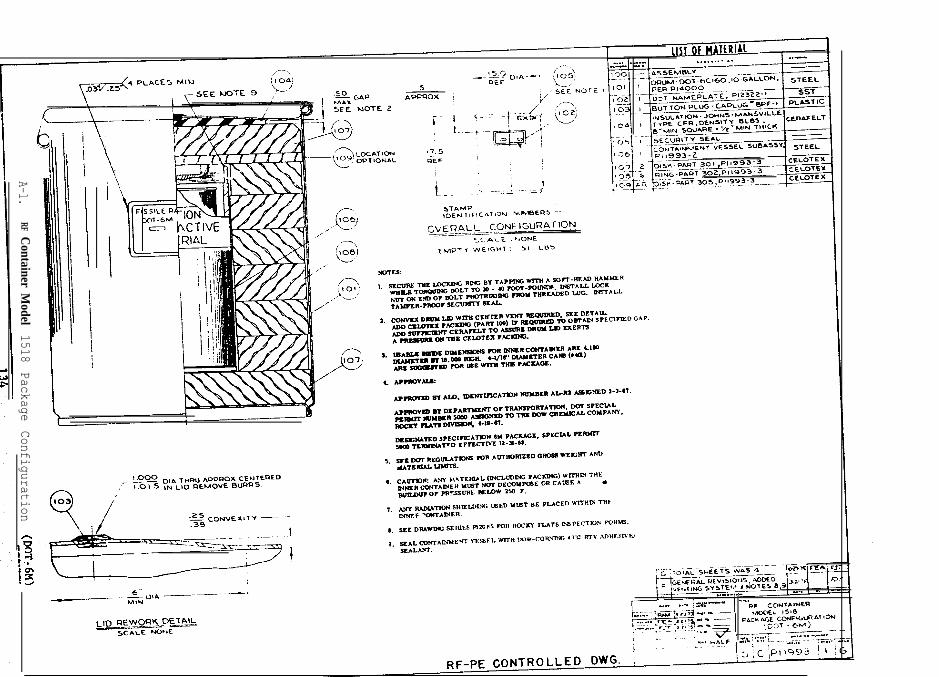
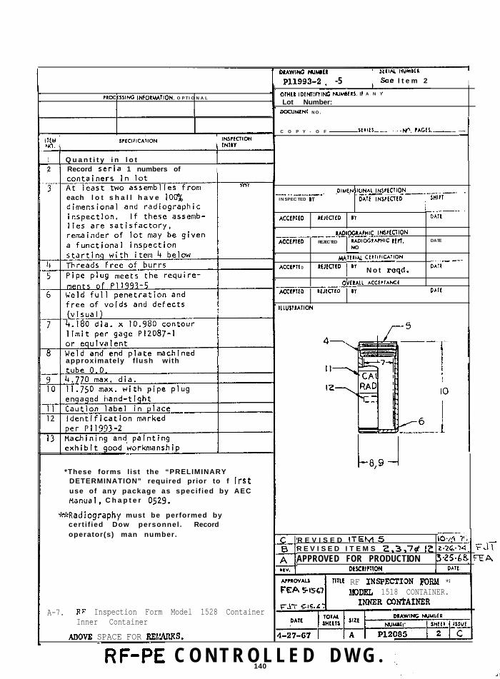
The original 6M packaging was Dow Chemical Corporation's Model 1518(Figure 1.1.1) a lo-gallon-size container approved by the U.S. AtomicEnergy Commission (now DOE) in March 196'I and issued DOT Special Permit 5000the foJ.lowing month. DOT Specification 6M was issued in December 1968 tocover a variety of similar ccntainers ranging in capacity from 10 to 110gallons. While the DOT 6M specification authorizes the IlO-gallon-size,packaging, the IlO-gallon version of the 6M is used infrequently in supportof DOE programs.
The 6M is a license-exempt, lightweight, economical, Type B packagethat is commercially available for a few hundred dollars and can he easil.yfabricated from common materials. This container has seen extensive servicesince 1967, and DOE contractors have a current inventory of 1,977 6Mpackagings.
Based upon many years of actual trar.*.portation history, the 6M hasbeer; shown to be a safe and reliable package. Although they have beenexposed to incidents of varying severity, there has never been a release ofradioactive contents from a 6M package.
Title 49 CFR Part 173,416 for Type B packages, and Part 173.417 forfissile materials describe the authorized contents of 6M packages (see Table1.1.1). Part 173.416 specifies the 6M packaging is only for solid or gaseousradioactive materials that do not undergo pressure-generating decompositionat temperatures up to 250°F (1'21°C) and that do not generate more than 10watts of radioactive decay heat. The specified limits in the regulatoryparagraphs cited above have been calculated on the basis of criticality andthe lo-watt decay heat restriction. Some DOE Certificates of Compliancehave been issued to provide for other radioactive contents or slightvariations in construction of the 6M packagings. These containers arereferred to in this report as “6M-like” packages.
For purposes of historical record, a file of "as-built" drawings for6M packagings is included as Appendix A of this report.
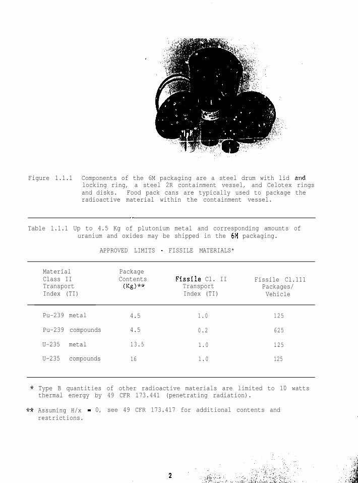
Figure 1.1.1 Components of the 6M packaging are a steel drum with lid andlocking ring, a steel 2R containment vessel, and Celotex ringsand disks. Food pack cans are typically used to package theradioactive material within the containment vessel.
__
Table 1.1.1 Up to 4.5 Kg of plutonium metal and corresponding amounts ofuranium and oxides may be shipped in the 61\1 packaging.
APPROVED LIMITS - FISSILE MATERIALS*
MaterialClass IITransportIndex (TI)
PackageContents(Kg)**
Fissile Cl. IITransportIndex (TI)
Fissile Cl.111Packages/Vehicle
Pu-239 metal 4.5 1.0 125
Pu-239 compounds 4.5 0.2 625
U-235 metal 13.5 1.0 125
U-235 compounds 16 1.0 125
* Type B quantities of other radioactive materials are limited to 10 watts, thermal energy by 49 CFR 173.441 (penetrating radiation).
.** Assuming H/x - 0, see 49 CFR 173.417 for additional contents and
restrictions. >i.:
1.0 General Information
1.2 CHARACTERISTICS OF OUTER DRUM
The outer steel structure of the 6M packaging is a DOT-Specificationdrum of varying sizes that provides impact and thermal protection.
.
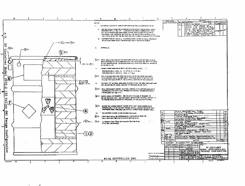
s;eneral construction requirements for a 6M packaging (49 CFR 178.104-3)call for a DOT-6C or -17C open-head steel drum or an equivalent, with ratedcapacity of 10 to 110 gallons. Because it is convenient to use commercialdrums, existing 6Ms have been constructed from 10, 15, 30, and 55-gallonsizes, or portions of such drums welded together (see the 60-gallon 6M inFigure 1.2.1.).
To comply with the letter and the intent of 49 CFR 178.104 and to bewithin the envelope of any designs tested, any "equiv$alent" drum must havethe characteristics given in Table 1.2.1.
Drum and closure construction as well as proper torquing methods forthe locking ring bolt (see Module 7.5) are critical to the function of thepackage during the 30-foot drop test.
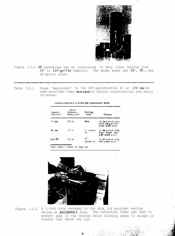
To prevent rupture during the thermal test, the drum must be vented.Two c.,mmon venting methods are a single l-inch hole centered in the lid,(Figure 1.2.2) or four O.S-inch holes located no further than 1.5 inchesbelow the top of the drum. For weather protection these holes must be closedwith a plastic plug or other fusible material.
A refractory material must be placed between the vent hole(s) and theinsulating rings for the best performance during the thermal test. A 0.5-inch Cerafelt blanket is ideal for this application because it provides hightemperature protection while allowing the package to vent through the porousstructure of the blanket.
It should be noted that the outer drum is not the containment boundaryfor the 6M packaging; such containment is provi.ded by the DOT-2R innercontairlment vessel. ‘ILlus, from a regulatory viewpoint it 1s permissible tohave vent holes in the outer drum without compromising the containmentboundary of the 6M packaging.
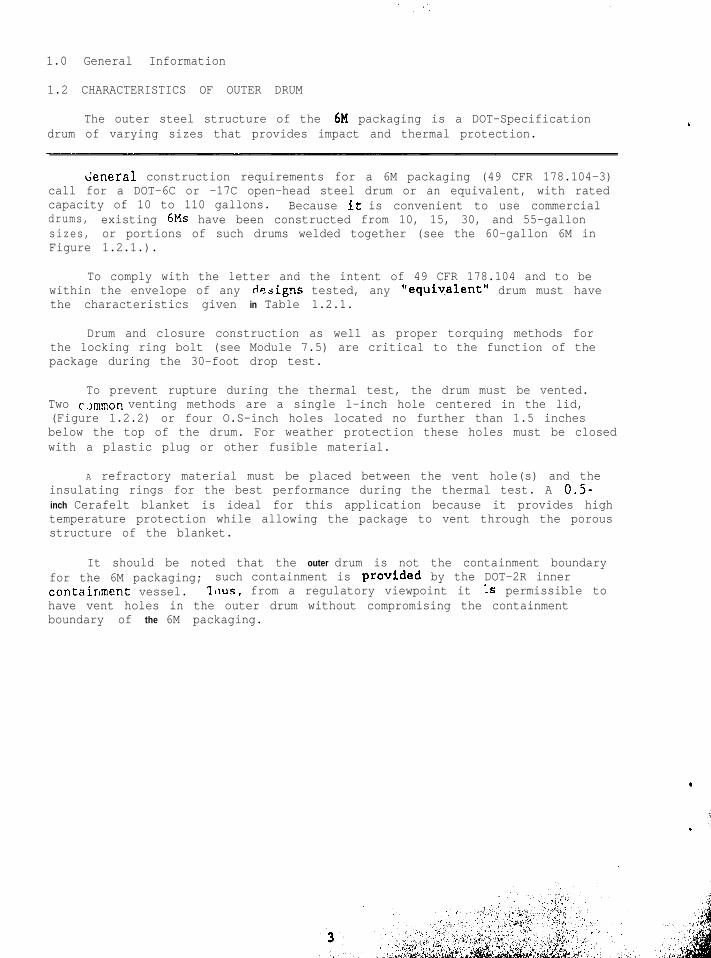
Figure 1.2.1 6M packagings may be constructed in many sizes varying fromlo- to IlO-gallon capacity. The drums shown are lo-, 30-, and60-gallon sizes.
Table 1.2.1 Drums "equivalent" to the DOT-specification 6C or 17C may beused provided they have equal or better construction and metalthickness.
CHARACTERISTICS RLJUIRED FDR “EQUIVALENT’ DRUM
netaCapacity Thickness. Rollillg(Gallons) Body E Lid Hoops ClOSUre
15 *ax 2 0 Ca NOM 16 Ca b o l t e d r i n g .drop fot8.d l u g s .5/16” steel b o l t
30 mar. 1 8 c.1 2 . r o l l e d . 12 Ca b o l t e d rink.in drop forged lugs.
S/l!” steel b o l t
over 30 1 6 Ca 3*. 12 G a b o l t e d r i n g .roller- in 5/S” steel b o l t
*One within 3 inches of Cop curl
Figure 1.2.2 A l-inch hole centered in the drum lid provides ventingduring an accident:1 fire. The refractory fiber pad used toprevent gaps in the Celotex while allowing gases to escape isvisible just below the lid.
1.0 General Information
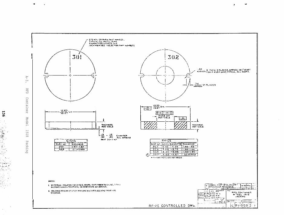
1.3 CHARACTERISTICS OF INSULATING DISKS AND RINGS
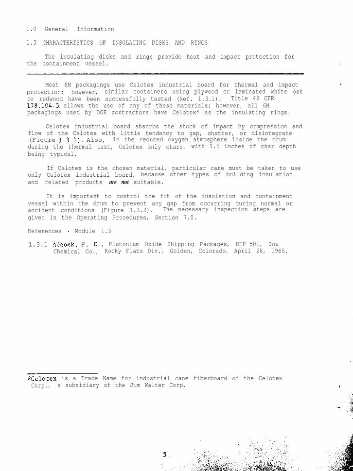
The insulating disks and rings provide heat and impact protection forthe containment vessel. .
Most 6M packagings use Celotex industrial board for thermal and impactprotection; however, similar containers using plywood or laminated white oakor redwood have been successfully tested (Ref. 1.3.1). Title 49 CFRl78.i04-3 allows the use of any of these materials; however, all 6Mpackagings used by DOE contractors have Celotex* as the insulating rings.
Celotex industrial board absorbs the shock of impact by compression andflow of the Celotex with little tendency to gap, shatter, or disintegrate(Figure 1.3.1). Also, in the reduced oxygen atmosphere inside the drumduring the thermal test, Celotex only chars, with 1.5 inches of char depthbeing typical.
If Celotex is the chosen material, particular care must be taken to useonly Celotex industrial board, because other types of building insulationand related products are not suitable.
It is important to control the fit of the insulation and containmentvessel within the drum to prevent any gap from occurring during normal oraccident conditions (Figure 1.3.2). The necessary inspection steps aregiven in the Operating Procedures, Section 7.0.
References - Module 1.3
1.3.1 Adcock, F. E., Plutonium Oxide Shipping Packages, RFP-501, DowChemical Co., Rocky Flats Div., Golden, Colorado, April 28, 1965.
*Celotex is a Trade Name for industrial cane fiberboard of the CelotexCorp., a subsidiary of the Jim Walter Corp.
Figure 1.3.1 This 55-gallon drum, weighing 535 pounds, was dropped froma height of 30 feet. Note how the Celotex insulation flowswith no tendency to gap or shatter.
Figure 1.3.2 The 0.5-inch maximum gap between the drum and Celotex isfilled with refractory fiber, thereby preventing gaps betweenthe insulation rings.
1.0 General Information
1.4 CHARACTERISTICS OF DOT-2R CONTAINMENT VESSEL
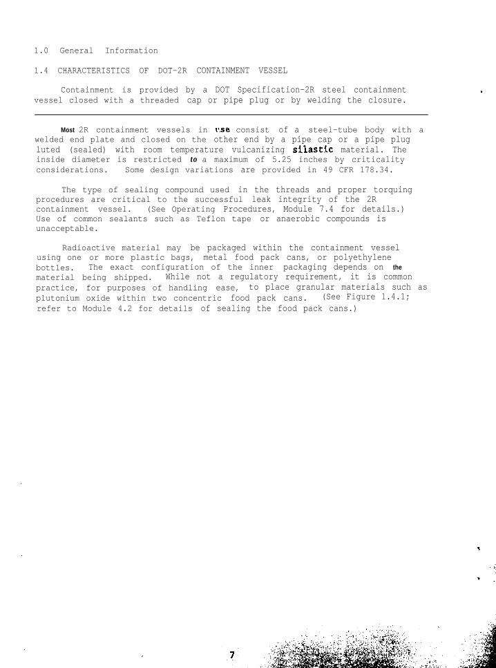
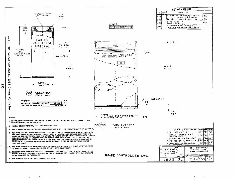
Containment is provided by a DOT Specification-2R steel containmentvessel closed with a threaded cap or pipe plug or by welding the closure.
Most 2R containment vessels in l'.se consist of a steel-tube body with awelded end plate and closed on the other end by a pipe cap or a pipe plugluted (sealed) with room temperature vulcanizing silastic material. Theinside diameter is restricted to a maximum of 5.25 inches by criticalityconsiderations. Some design variations are provided in 49 CFR 178.34.
The type of sealing compound used in the threads and proper torquingprocedures are critical to the successful leak integrity of the 2Rcontainment vessel. (See Operating Procedures, Module 7.4 for details.)Use of common sealants such as Teflon tape or anaerobic compounds isunacceptable.
Radioactive material may be packaged within the containment vesselusing one or more plastic bags, metal food pack cans, or polyethylenebottles. The exact configuration of the inner packaging depends on thematerial being shipped. While not a regulatory requirement, it is commonpractice, for purposes of handling ease, to place granular materials such asplutonium oxide within two concentric food pack cans. (See Figure 1.4.1;refer to Module 4.2 for details of sealing the food pack cans.)
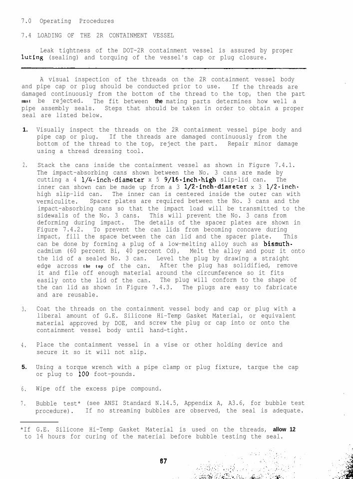
Figure 1.4.1 This 2R containment vessel for a lo-gallon 6M package holdstwo No. 2 l/2-size food pack cans.
1.0 General Information
1.5 SUMMARY OF 6M PACKAGING REGULATORY TESTS AND ANALYSIS
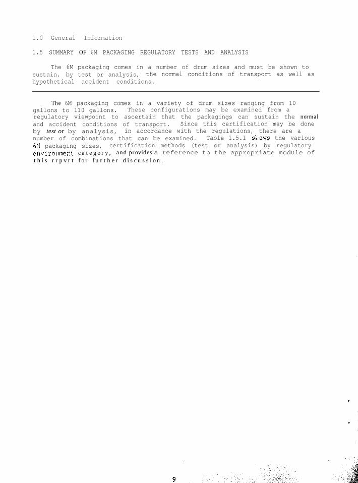
The 6M packaging comes in a number of drum sizes and must be shown tosustain, by test or analysis, the normal conditions of transport as well ashypothetical accident conditions.
The 6M packaging comes in a variety of drum sizes ranging from 10gallons to 110 gallons. These configurations may be examined from aregulatory viewpoint to ascertain that the packagings can sustain the normaland accident conditions of transport. Since this certification may be doneby test or by analysis, in accordance with the regulations, there are anumber of combinations that can be examined. Table 1.5.1 si,ows the variousGM packaging sizes, certification methods (test or analysis) by regulatoryen\:ironment c a t e g o r y , and provides a reference to the appropriate module oft h i s r r p v r t f o r f u r t h e r d i s c u s s i o n .
Table 1.5.1 The safety evaluation for 6M packaging has addressed a nL,,l[Jerof packaging si.zes and has been accomplished by a combinationof tests and analysis.
SUMMARY OF 6M PACKAGING REGULATORY CONSIDERATIONS-
The 6M packaging meets the general standards for all Type A and Type Bpackages.
Chemical and Galvanic Reactions
Requirement: A Lackage must be of materials and construction thatassure there will be no significant chemical, galvanic, or other reactionamong the packaging components or between the components and the packageconients , including possible reaction resulting from in-Leakage of water iothe maximum credible extent.
Analysis: The steel, Celotex (or wood), and inner packaging materialshave been selected to meet the above requirements. Adequacy has beendemonstrated by 19 years of service.
Security Seal
Requirement: The outside of a package must incorporate a feature, suchas a seal, that is not readily breakable. This feature, while intact,provides evidence that the package has not been opened by unauthorizedpersons.
Analysis: The .!rum is closed using a bolted ring with a lock nut tosecure the Lid to the drum body. In addition, a Lead-wire security sealprovides a tamper-indicating device that would indicate any attempt to gainunauthorized entry into the packaging.
Lif:ing Device
Requirement: Any lifting attachment that is a structuralpackage must be designed with a minimum safety factor of 3 aga iwhen used to Lift the package in the intended manner. It alsodesigned so failure of any Lifting device under excessive Loadimpair the ability of the package to meet other requirements._ . . _.^ .
part of thenst yieldingmust bewill notAny other
structural part of the package that could be used to Lfrt the package mustbe capable of being rendered inoperable for lifting the package duringtransport, or must be designed with strength equivalent to that required forLifting attachments.
Analysis : No lifting devices are provided, nor are they required. Formost sizes in the 6M family, the packages are light enough to be handledmanually or they are palletized. The largest size 6X, the llO-gallon, isused infrequently.
This page left intentionally blank.
2 .rj S:ructural Evaluation
2.1 GENERAL STANDARDS FOR ALL PACKAGES (CONTTWED)
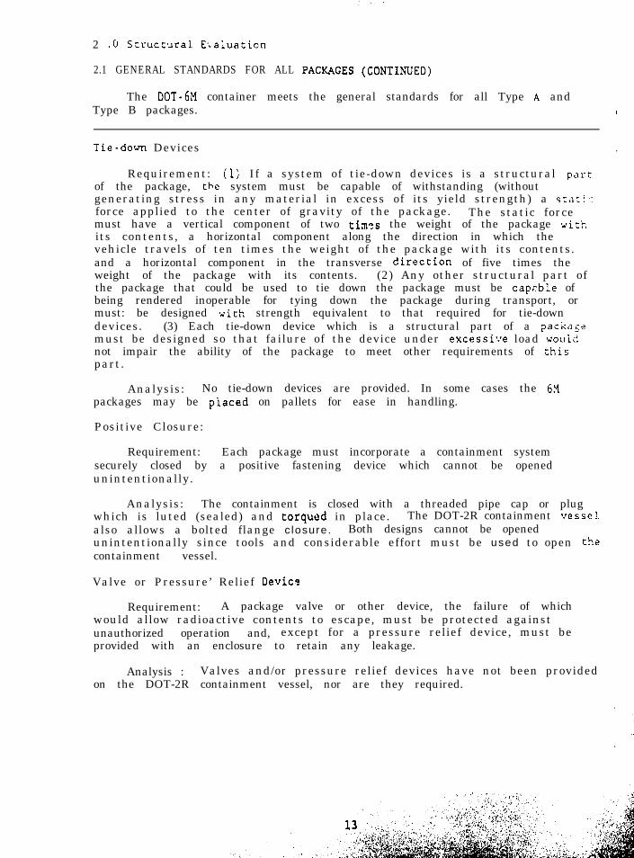
The DOT-6M container meets the general standards for all Type A andType B packages. 1
Tie-don Devices .
Requirement: (I) If a system of tie-down devices is a structural partof the package, the system must be capable of withstanding (withoutgenerating stress in any material in excess of its yield strength) a srnci.force applied to the center of gravity of the package. The static forcemust have a vertical component of two timn,s the weight of the package withits contents, a horizontal component along the direction in which thevehicle travels of ten times the weight of the package with its contents.and a horizontal component in the transverse dfrection of five times theweight of the package with its contents. (2) Any other structural part ofthe package that could be used to tie down the package must be capcble ofbeing rendered inoperable for tying down the package during transport, ormust: be designed *dith strength equivalent to that required for tie-downdevices. (3) Each tie-down device which is a structural part of a packa<?must be designed so that failure of the device under excessi*.re load wouldnot impair the ability of the package to meet other requirements of :hispart.
Analysis: No tie-down devices are provided. In some cases the 6Xpackages may be piaced on pallets for ease in handling.
Positive Closure:
Requirement: Each package must incorporate a containment systemsecurely closed by a positive fastening device which cannot be openedunintentionally.
Analysis: The containment is closed with a threaded pipe cap or plugwhich is luted (sealed) and torqued in place. The DOT-2R containment vessel.also allows a bolted flange c losure. Both designs cannot be openedunintentionally since tools and considerable effort must be used to open thecontainment vessel.
Valve or Pressure’ Relief Devic?
Requirement: A package valve or other device, the failure of whichwould allow radioactive contents to escape, must be protected againstunauthorized operation and, except for a pressure relief device, must beprovided with an enclosure to retain any leakage.
Analysis : Valves and/or pressure relief devices have not been providedon the DOT-2R containment vessel, nor are they required.
.
.
(,.’ .:
: .
Excessive Surface Temperature
Requirement: A package must be designed, constructed, and prepared foLtransport so that in still air at 38°C (lOOoF) and in t!;e shade, noaccessible surface of a package would have a temneratllro c::c~;J;II~ 5u-C(122°F) in a nonexclusive use shipment or 82°C (180°F) in an exclusive useshipment.
Analysis: Calculations (see module 3.3) show that under the conditionsstated above the lo-gallon 6M packaging design with a maximum FcLlltisslbleloading of 10 watts will have a surface temperature less than 114°F. Largerpackages will be at lower temperatures.
Load Resistance
Requirement: Regarded as a simple beam supported at its ends along anymajor axis, the packaging shall be capable of withstanding a static load.normal to and uniformly distributed along its length, eqclnl to five timesits fully loaded weight, without generating stress in any material of thepackage in excess of its yLeid strength.
Analysis: Module 2.9 shows the results of such an analysis for theworst case, the geometry of a IlO-gallon size 6M. The results of theanalysis show that the IlO-gallon 6M will have bending stressessignificantly below the yield stress of the outer metal drum.
2.0 Structural Evaluation
2.2 GENERAL REQUIREMENTS FOR NORMAL CONDITIONS OF TRANSPORT - I
The 6M packaging complies with all requirements for normal conditionsof transport as demonstrated by analysis and actual tantc.--
Evaluation of each package design under normal conditions of transportmust include determining of the effect of certain conditions and tests onthat design. A separate specimen may be used for each test as long as it isfirst subjected to the water spray test.
Compliance with requirements must be based on the ambient temperaturepreceding and following the tests. This temperature must remain constant attfT$ value between -29°C (-20°F) and +38"C (100°F) that is most unfavorablefor the feature cinder consideration. The internal pressure within thecontainment system must be considered to be the maximum normal operatingpressure, unless a lower internal pressure consistent with the ambienttemperature that precedes and follows the tests is more unfavorable.
Heat
Requirement: An ambient temperature of 30°C (100°F) in still air, withinsolati.on temperatures according to the following table.
----
Form and Location of Surface Temperature inTotal Insolation*
(g Cal/cm)**
Flat surface, transportedhorizontally
BaseOther surfaces
None800
Flat surface, not transportedhorizontally
Curved surface
200
400
*Position must be .;laintained for 12 hours.**Gram-calories per centimeter.
Analysis: The steady-state analysis involved thermal loading due tothe lo-watt internal heat-generating capacity and solar insolation specified
by the regulations. The results of the steady-state analysis are given inModule 3.3, and are summarized as maximum temperatures at the surface of theinner containment vessel of 117'C (243.F) for the lo-gallon-size 6M andmaximum surface temperatures of 103.C (217'F) for the 55-gallon-size 6M.
References - Module 2.2.
2.2.1 Sanchez, L.C., Longenbaugh, R.S., Moss, M., Haseman, G.M., FowlerW.E., Roth, E. P., Thermal Analysis of the lo-Gallon and the 55-Gallon 6M Containers With Thermal Boundary Conditions Correspondingto lOCFR71 Normal and Accident Conditions, SAND87-1896, TTC-0748,Sandia National Laboratories, Albuquerque, New Mexico, March 1988.
2.0 Structural Evaluation
2.3 GENERAL REQUIREMENTS FOR NORMAL CONDITIONS OF TRANSPORT - II
The DOT-6M container complies with all requirements for normalconditions of transport as demonstrated by analysis and actual tests.
Cold
.
Requirement: An ambient temperature of -40°C (-40°F) in still air andshade.
Analysis: Theplastic vent plugs i-54°C (-65°F); thusrequirement. The ca rbrittle fracture at
only materials affected by cold temperatures are then the metal outer drum. They function satiscactorily atthe performance capability exceeds the regulatory
bon steel in the DOT-6C or -17C drums may be subject to-4O"F, hut a broad base of field experience with 6M
packages has not uncovered any drum failures due to low-temperature drumproperties.
Many cases are on record wherein failures have occurred for presumablyadequately designed components, such as the metal drum of the 6M whenfabricated from a ductile material like mild steel. No clear line ofdistinction exists between the ductile and the brittle response of normallyductile materials. When notch-impact tests are conducted on ductilematerials, a "transition temperature" occurs below which they can behave ina brittle fashion, especially if the loads are applied very rapidly to thecomponent (Ref. 2.3.1). While brittle behavior of the 6M metal drums istheoretically possible, no such behavior has been observed in approximately20 years of actual field use of the 6M packaging.
Vibration
Requirement: Vihration normally incident to transport.
Analysis: The 6M packaging has no component that can be damaged byvibration encountered during normal transport. Thousands of shipments havebeen made without any evidence of damage or loss of contents due to normalvibration. A locking nut is applied to the lid closure ring bolt which, inaddition, is secured with a lead seal. This seal acts as a safety wire toprevent loss of the lid-closure locking nut due to vibration.
Water Spray
Requirement: A water spray that simulates exposure to rainfall ofapproximately 5 centimeters (2 inches) per hour for at least 1 hour.
. Analysis:from this test.
The steel drum and vent plug are not susceptible to damage
References Module 2.3
2.3.1 Faupel, J. H., Engineering Design, Chapter 1, Materials andProperties, John Wiley and Sons, Inc., 1964.
2.C Structural Evaluation
2.4 GENERAL REQUIREMENTS FOR NORMAL CONDITIONS OF TRANSPORT - III
The DOT-6M container complies with all requirements for normalconditions of transport as demonstrated by analysis and actual tests.
Free Drop
Requirement: Between 1.5 and 2.5 hours after the conclusion of thewater spray test, a free drop through the distance specified below onto aflat, essentially unyielding, horizontal surface, striking the surface in aposition for which maximum damage is expected. For Fissile Class IIpackages, this free drop must be preceded by a free drop from a height of0.3 meter (1 foot) on each corner, or, in the case of a cylindrical FissileClass II package, onto each of the quarters of each rim.
CRITERIA FOR FREE DROP TEST
Package Weight Free-Droo Distance
Kilograms Pounds Meters Feet
5000 or less 11000 1.2 45000 to 10000 11000 to 22000 0.9 3
10000 to 15000 22000 to 33000 0.6 2>15000 >33000 0.3 1
Analysis: A number of free drop tests have been performed on the 6M,resulting in little or no damage to the outer drum (see Refs. 2.4.1 and2.4.2). Because little or no damage occurred, no physical damage detrimentalto the 6M would be sustained in accident-condition transport tests,
References - Module 2.4
2.4.1 Adcock, F. E., McCarthy, J. D., Wackier W. F., Rocky Flats Model 203-1 Container (AEC-AL USA/5332/BLF), Safety Analysis Report forPackaging (SARP), RFP-1867, Rev. 1, Feb 27, 1974.
2.4.2 Adcock, F. E., Wackier W. F., RFP Container, Model 1518 for FissileClass II and Class III Shipments, RFP-1042, 1968.
. , ’ .,_ :
a* ,.‘,
. ?
This page left intentionally blank.
’. .
2.0 S, true tural Evaluation
2.5, GENE&AL REQUIRRMENTS FOR NORMAL CONDITIONS OF TRANSPORT - IV
The 6M packaging complies with all requirements for normal conditionsof transpart as demonstrated by analysis and actual tests. .
CorJnar Drop .
Requirement : A free drop onto each corner of the package insuccession, or in the case of a cylindrical package onto each quarter ofeach rim, from a height of 0.3 meter (1 foot) onto a flat, essentiallyunyielding, hqrizontal surface. This test applies only to fiberboard or woodrectangular packages not exceeding 50 kilograms (110 poundsj and fiberboardor wood cylindrical packages not exceeding 100 kilograms (220 pounds).
Analysis : The corner drop test is not applicable to the 6M because the6M is not a fiberboard or wood box configuration.
Penetration
Requirement: Impact of the hemispherical end of a vertical steelcylinder of 3.2 centimeters (1.25 inches) diameter and 6 kilograms (13poun,de) mass, dropped from a height of 1 meter (40 inches) onto the exposedsytface of the package that is expected to be most vulnerable to puncture.The long axis of the cylinder must be perpendicular to the package surface.
Analysis : Several penetration tests have been performed on the 6H(Refs, 2.2,l and 2.3.1), resulting in only minor damage to the metal drumand no rupture of its metal surface (see Figure 2.5.1).
Compression
Requirement: For packages with 8 m8ss up to 5000 kilograms, thepackqge must b e subjected for a period of 24 hours to a compressive loadappl,ied uniformly to its top and bottom. The package must be in theposition in which it would normally be transported. The compressive loadmust be the greater of the following:
1. The equivalent of five times the weight of the package, or;
2. The equivalent of 12.75 kilopascals (1.85 pounds per square inch)muAtlpLied by the vertically projected area of the package.
AnaJysis : Compression tests of various sizes of steel drums have beencgn&ctrd’at loadings in excess of five times the p8Ckag8 weight with nomec)suri$hls deqormation. A summary of the test loads is given in Table2,;s. 1,
References I M o d u l e 2 . 5.
2.5.1 i$dJ.ing, D. A., Hopkins D. R., Wilson, S. C., DOT 7A , Type ACeqftf$catian ?ocment, Mound Laboratory, Monsanto Research Corp.,
;r.$*2 ~#wlqIIgipw J* A., Safety Analysis Report for Packaging, Type L-10q$asql >T Shipping ContaJner, ARH-3050, May 1974. (Note: The L-10 is a_ .
4-Foot Free DropOn Corner
Figure 2.5.1 The results of the penetration test for normal conditions oftransport sl~o:~ only minor damage to the 6M drum.
2.6 REQUIREMENTS FOR HYPOTHETICAL ACCIDENT CONDITIONS
The 6M meets all hypothetical accident condition tests..
Review of the published and unpublished literature shows the 6M hasbeen tested to current regulations (with the exception of the 50-footimmersion test) and other criteria more than any other radioactive wastepackaging in use. The original tests of a lo-gallon-size package wereperformed by Dow Chemical Company in 1967 to qualify for Special Permit 5000(Ref. 2.6.1). Various additional tests were performed later in 1967 toconfirm the higher gross weights proposed for the DOT Specification 6M(Refs. 2.6.2, 2.6.3).
.
Sandia National Laboratories tested the 6M and two other containers toflight recorder standards, which include 1000-g shock, 5000-pound staticcrush, and a half-hour thermal test at 1100°C (2000°F) (Ref. 2.6.4). Thesepackagings were loaded with uranium oxide, SO leakage, should any occurduring the accident tests, could be readily determined. Although the 6Msuffered considerable damage, no uranium oxide leakage was found. It isimportant to note that proper drum closing, venting procedures, and improvedthread sealants contributed to the success of this test.
Other tests performed on 6M packages demonstrate they exceed regulatorytest standards. A 300-foot drop and a 983°C (1800°F) fire for 1 hour showedthe partial loss of the drum lid during both thermal and drop tests; lack ofa venting system and improper locking-ring closing techniques caused the lidloss (Ref. 2.6.5). Dye solution leaked from the containment vessels duringseveral tests when an improper thread sealant was used. These tests havecontributed greatly to the knowledge of container performance during severeover-tests and resulted in improved operating procedures. (Details of theaccident condition tests are given in Modules 2.7 through 2.10.)
References - Module 2.6
2.6.1 Adcock, F. E., Wackier W, F., RFP Container-Model 1518 for FissileClass II and Class III Shipments, RFP-1042, Dow Chemical Co., J-968.
2.6.2 Adcock, F. E., McCarthy J. D.', Wackier W. F., Rocky Flats Model 203-lContainer (AEC-AL USA/5332/BLF) Safety Analysis Report for Packaging(SARP), RFP-1867, Rev. 1, Feb. 27, 1974,
2.6.3 Adcock, F.E.! Wnckler W. F., Preliminary Report, Drop-Test of Lead-filled DOT6-M Containers, Dow Chemical Co. June 6, 1968.
2.6.4 McWhirter, M., et al., Final Report on Special Tests of PlutoniunOxide Shipping Containers to FAA Flight Recorder SurvivabilityStandards, SAND75-0446, Sandia National Laboratories, Albuquerque,New Mexico, September 1975.
2.6.5 Bonzon, L. L., Final Report on Special Impact Tests of PlutoniumShipping Containers, Description of Test Results, SAND76-0437, SandinNational Laboratories, February, 1977.
.
1.
::.
-.-_..
2.0 Structural Evaluation
2.7 RESULTS OF ACCIDENT CONDITION TESTS - FREE DROP
Since 1967, many 30-foot free drop tests have been conducted on 6M and6M-like packagings of lo- to 55-gallon size, resulting in little or nodamage to the packagings.
.
Free Drop.
Requirement: A free drop of the package through a distance of 30 feetonto a flat, essentially unyielding, horizontal surface, striking thesurface in a position in which maximum damage to the package is expected.
Analysis: The results of free drop tests are reported in Refs. 2.7.1and 2.7.2 for 30-gallon and lo-gallon 6M packages. These tests involveddropping 6Ms in an orientation such that the point of impact was on the drumcorner near the locking-ring bolt. Minor deformation occurred at the pointof impact, but the locking-ring and cover remained intact, with no Celotexexposed.
Overall damage was expected to be maximum with a corner drop: however,additional drops were made to maximize specific types of damage. The lo-gallon 6M (Ref. 2.7.2) and 30-gallon "6M-like" containers were dropped ontheir sides to maximize flattening or loss of spacing. Results were a 0.20-and a 0.25-inch decrease in effective radius. Two lo-gallon 6Ms (Ref.2.7.3) were dropped 30 feet end-on to maximize crushing of the Celotcx bythe containment vessel. No permanent Celotex deformation was noted for atypical containment vessel weighing 20 pounds. A lead-filled containmentvessel weighing 71 pounds resulted in a Celotex compression of approximately0.7 inch. Even with the deformations in the Celotex noted, both packagesremained functional and passed subsequent thermal tests.
References - Module 2.7
2.7.1 Adcock, F. E., McCarthy, J. D., Wackier, W. F., Rocky Flats Model2030-l Container (AEC-AL USA/5332/BLF), Safety Analysis Report forPackaging (SARP), RFP-1867, Rev, 1, Feb. 27, 1974.
. 2.7.2 Adcock, F. E., Wackier, WClass II and Class III Sh i
. 2.7.3 Adcwck, F. E., Wackier, Wfilled DOT-6M Containers,
F ., RFP Container, Model 1518 for Fissilepments, RFP-1042, 1968.
F Preliminary Report, Drop-Test of Lead-Doi'Chemical Co., June 6, 1968.
26 ',,., : -',-_..,.
2.0 Structural Evaluation
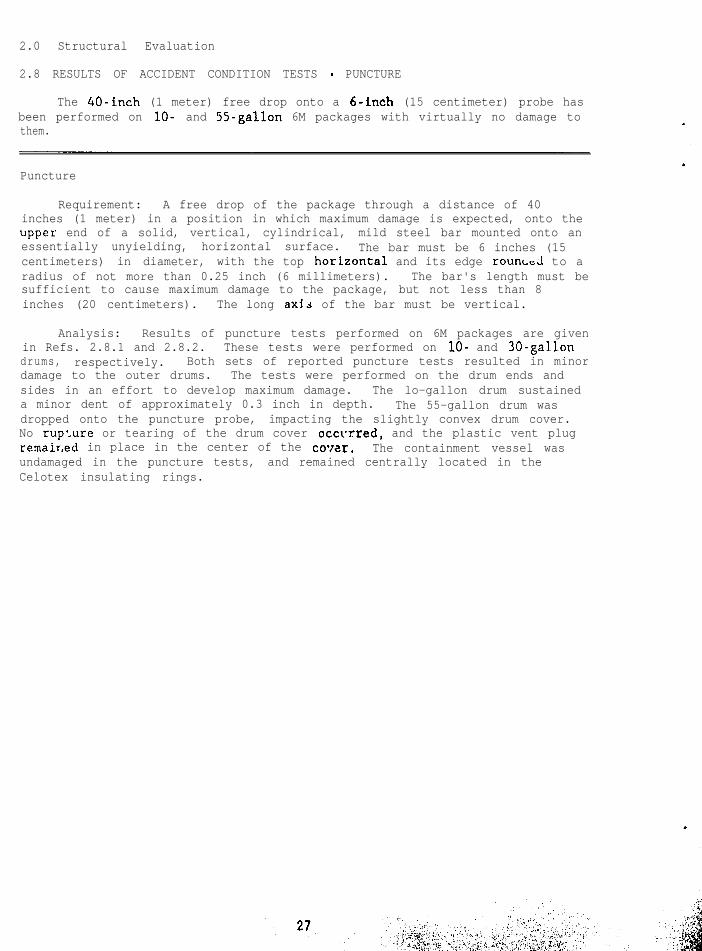
2.8 RESULTS OF ACCIDENT CONDITION TESTS - PUNCTURE
The 40-inch (1 meter) free drop onto a 6-inch (15 centimeter) probe hasbeen performed on lo- and 55-gallon 6M packages with virtually no damage tothem.
Puncture
Requirement: A free drop of the package through a distance of 40inches (1 meter) in a position in which maximum damage is expected, onto theuppes end of a solid, vertical, cylindrical, mild steel bar mounted onto anessentially unyielding, horizontal surface. The bar must be 6 inches (15centimeters) in diameter, with the top horizontal and its edge rounLt;J to aradius of not more than 0.25 inch (6 millimeters). The bar's length must besufficient to cause maximum damage to the package, but not less than 8inches (20 centimeters). The long axis of the bar must be vertical.
Analysis: Results of puncture tests performed on 6M packages are givenin Refs. 2.8.1 and 2.8.2. These tests were performed on lo- and 30-gallondrums, respectively. Both sets of reported puncture tests resulted in minordamage to the outer drums. The tests were performed on the drum ends andsides in an effort to develop maximum damage. The lo-gallon drum sustaineda minor dent of approximately 0.3 inch in depth. The 55-gallon drum wasdropped onto the puncture probe, impacting the slightly convex drum cover.No rupture or tearing of the drum cover occurred, and the plastic vent plugremair.ed in place in the center of the covar. The containment vessel wasundamaged in the puncture tests, and remained centrally located in theCelotex insulating rings.
References - Module 2.8
2.8.1 Adcock, F. E., Wackier, W. F., RFD Container, Model 1518 for FissilcClass II and Class III Shipments, RFP-1042, 1968.
2.8.2 Adcock, F. E., McCarthy, J. D., Wackier, W. F., Rocky FlatsModel 2030-l Container (AEC-AL USA/5332/BLF), Safety Analysis Reportfor Packaging (SARP), RFP-1867, Rev. 1, Feb. 27, 1974.
2 0 Structural Evaluation
2.9 RESULTS OF ACCIDENT CONDITION TESTS - THERMAL
Roth by analysis and by testing, the 6M package has been shown tosatisfy the requirements of the thermal testing undar the hypotheticalaccident conditions of transport,
---...- - -
‘l‘ll<~ L-In;1 1
I<t:<l\lircments : Esp(,sur~: of the whole specimen for not less than 301~1itj11t.t:~ to a heat flux 11r1t less than that of a radiation environment cfHlji)“C: (1475°F) , with an rmissi\i ty coefficient of at least 0.9. For purposesof calculation, the surface absorptivity must be either that value which thepackage may be expected to possess if exposed to a fire, or 0.8, whicheveris greater. In addition, when significant, convective heat input must beinc:!l.:l!ed on the basis of’ still -ambient air at 800°C (1475°F). A r t i f i c i a lcool i 11:: must not be appl i ec1 afttar cessation of external heat input, and anyt:o!ni)llstion of constructiorl m,lterials must be allowed to proceed until it: r’!-irli rlnttbs naturally. ‘l‘hct (.f tects of solar radiation may be neglectedl.ti. f ‘, t-c , rlurinp,, And aft.cr t.l1r* t-est.
A.i:alysis : Ttlermnl (.~:;t.s were conducted in a 275-kilowatt inductiontliL-n.lce (Ref .2.9.1) preheated to 830°C (1525°F) before the 30-minute testr1111s at 800°C (1675°F). The test specimen was a “6M-like” 30-gallon drumconFiguration instrumented wit-t] thermocouples to continuously recordirlterior temperatures durir.g t-he test. The test results are shown in Figure2.3.1. The outer surface of the containment vessel reached a peak! c!mpc’rature o f gt;“C ( 2 0 5 ° F ) This temperature occurred approximately 211011~s aft.er the start of thp Lest and represents a rise of about 57°C( 1 ‘35” F) at)ove that of the package components at the start of the test.
I<pf:, 2.9.2 reports an additional set of thermal tests on a lo-gallonII:!, (see Figure 2 . 9 . 1 ) . ‘I’llc package was placed in a preheated inductionf , , 1’ 1 I n c e and exposed to t:hc thermal environment for 30 minutes. Thet.Ilc!rmoco\lples shorted out during the first 5 minutes of exposure, so thei rltcrnal temperatures could not be monitored directly. Temperature-r;clnsitive pc:llets were placed on the cans inside the containment vessel and011 t-he exteri.or of the containment vessel. The 93°C (200°F) pellets on theside and bottom of the containment vessel showed that 93°C (200°F) had justI)cbcrl I-enchcd. The pellets on the cans in the containment vessel indicated65°C (150°F) had been exceeded, but 79°C (175°F) had not been reached(Fighire 2 . 9 . 2 ) . No sc-arching of paint on the radiation label occurred, nortlitl t.tlc? mctnl cans in the containment vessel swell.
‘t’tlc magnitude of tile temperatures inside and near the containmentyrcs:sel were less than the 149°C (300°F) required for gasket material(zornpatibility (Spec i f i ca t i on ?R for the containment vessel). ’
Figure 2.9.2 Temperature labels on the 2R containment vessel show that93°C (200°F) was exceeded, but 107°C (225°F) was not reached
References - Module 2.9
2.9.1 Adcock, F. E., McCarthy, J. D., Wackier, W. F., Rocky Flats Model2030-l Container (AEC-AL USA/5332/BLF), Safety Analysis Report forPackaging (SARP), RFP-1867, Rev. 1, Feb. 27, 1974.
2.9.2 Adcock, F. E., Wackier, W. F., RFP Container, Model 1518 for FissileClass II and Class III Shipments, RFP-1042, The DOW Chemical Co.,Rocky Flats Div., Golden, Colorado, 1968.
Figure 7.9.1 Typical depth of char after the thermal test is 1.5 inchesradially. Note pristine condition of containment vessel.
.
30
‘*
:.,.’.‘I. .,,a.
, I‘ I.,, .,:z:*.,: 2. .
2.0 Structural Evaluation
2.10 RESULTS OF ACCIDENT CONDITION TESTS - TRANSIENT THERMAL ANALYSIS
Both by analysis and by testing, the 6M has been shown to pass therequirements of the transient thermal conditions under hypothetical accidentconditions of transport.
Transient Thermal Analysis
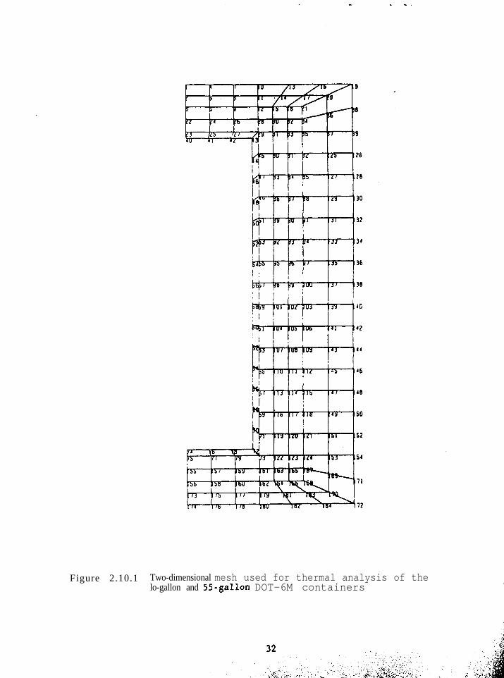
A transient thermal analysis was performed for the accident conditionsof transport for the lo-gallon and 55-gallon sizes of the DOT-6M. Theanalysis used the Q/TRAN thermal systems analysis code, Ref. 2.10.1, whichuses the traditional thermal network approach. Q/TRAN has been used inthermal benchmark problems for spent fuel casks, Refs. 2.10.2 to 2.10.5. Thegeometry of the thermal model is shown in Figure 2.10.1. The model usesthree methods of energy transfer, (1) conduction heat transfer within thesolid regions of the DOT-6M; (2) natural convection from the surfaces of the6M container to a still air environment; and (3) thermal radiation betweenthe surfaces of the 6M container and the environment.
The results for a transient thermal analysis were obtained from a two-dimensional model. Selective thermal results were obtained for the regionof the 2R inner containment vessel, the mid-thickness location of theCelotex thermal insulation material and the outer surface of the DOT-6M.These results are given in Module 3.6. The variation of temperature withrespect to time for the transient analysis is presented in Table 3.6.1 forthe lo-gallon configuration of the DOT-6M since it has the least amount ofthermal insulation.
References - Module 2.10
2.10.1 Rockenbach, F. A., Q/TRAN, Version 1.2 User's Manual, PD EngineeringInc., Santa Ana, CA, May 1986.
2.10.2 Sanchez, L. C., Performance Testing of Thermal Analysis Codes forNuclear Fuel Casks, SAND84-1854, TTC-0509, Sandia NationalLaboratories, Albuquerque, New Mexico, January 1987.
2.10.3 Sanchez, L. C., Solutions Obtained To International BenchmarkingProblems for Nuclear Fuel Casks Using Q/TRAN, SAND85-2621, TTC-0631,Sandia National Laboratories, Albuquerque, New Mexico, February1987.
2.10.4 Mantuefel, R. D., Klein, D. E., and Yoshimura, H. R., Benchmarkingthe Q/TRAN Thermal Analysis Code, IAEA-SM-286/95P, Proceedings ofPATRAM-86, Davos, Switzerland, June 16-20, 1986, pp 465-474.-
2.10.5 Glass, R. E., Thermal Benchmarking: A Status Report, IAEA-SM-286/1OOP, Proceedings of PATRAM-86, Davos, Switzerland, Junepp 497-499.
16-20, .
.
.
. Figure 2.10.1 Two-dimensional mesh used for thermal analysis of thelo-gallon and 55-gallon DOT-6M containers
32
2.0 Structural Evaluation
2.11 RESULTS OF ACCIDENT CONDITION TESTS - THERMAL STRESSES
The thermal gradients in the region of the containment vessel were sosmall they produced negligible thermal stresses in the body of thecontainment vessel.
Thermal Stresses
The heat generation region in the transient thermal analysis modelconsists of the radioactive material within the containment vessel and thecontainment vessel itself. The maximum thermal gradiLnt across thethickness of the 2R containment vessel is small, less than 1°C (2°F). Underthese conditions, for such small thermal gradients, no significant thermalstress occurs in the walls of the containment vessel. (See Module 3.6 fordetails of the transient thermal analysis.)
This page left intentionally blank.
2 .O Structural Evaluation
2.12 LOAD RESISTANCE OF THE 6M PACKAGING
The load resistance of the 61-l packaging, as measured by its bendingresistance , produce!; stresses significantly below the yield stress of theouter metal drum.
.
Load Resistance
Requirement: Rcgnrticd a s a simple beam supported at its ends along anymajor axis, the 6M packaging should be capable of withstanding a static loadequal to f ive t imes i t.s fully loaded weight. The load should be normal toand uniformly distributed along the 6M’s length, an? should not generatestress in any material of the packaging in excess of its yield strength.
Analysis: Ar,!;urninj; ,a IlO-gallon 6M package (as a limiting case) to beloaded ns spccifircl 3bovc~, the stress on the drum may be calculated asf o l l o w s :
Total. static load: ‘d = S s 640 - 3200 pounds
Menm l e n g t h : I . - 69.6 i n c h e s
Drurn outside diameter: Do = 22.6 inches
D r u m i n s i d e d i a m e t e r : D i = 2 2 . 5 i n c h e s
Mas i mum bend i rig mornen t : Mmnx =i WI,/8 - 27840 pound-inches
Momcn t o i I no I’: i ;I : I - :/6/o ((Do)A - (Di)4) - 2 7 0 . 5 i n c h e s 4
Distance f t’om neutral nsis: c -j Do/2 - 11.3 inches
Maximum bending stress: = (Mmax) c/I - 1163 pounds per square inch (psi).
T h e y i e l d s t r e s s f o r c a r b o n s t e e l i s 35000 psi. Thus, the 6M’s 1163 psibending stress (the effective measure of the bending resistance of the 6Mpackaging) is significant1.y below the yield stress for carbon steel, with asafety factor of approximately 30. A similar analysis for a lo-gallon-size6 M gave a n even srnal.ler b e n d i n g s t r e s s .
This page left intentionally blank.
2.0 Structural Evaluation
2.13 RESULTS OR ACCIDENT CONDITION TESTS - IMMERSION
The 6M packaging meets the conditions of the water immersion test
Water Immersion
Requirement: For Fissile Material, in those cases where waterinleakage has not been assumed for criticality analysis, the specimen mustbe immersed under a head of water at least 0.9 meters (3 feet) for a periodof not less than 8 hours and in the attitude at which maximum leakage isexpected.
Analysis: Immersion tests were performed on 6M packagings of the IO-and 30-gallon size (see Refs. 2.13.1 and 2.13.2). The containment vesselswere determined to be watertight.
References - Module 2.13
2.i3.1 Adcock, F. E., McCarthy, J. D., Wackier, W. F., Rocky Flats Model2030-l Container (AEC-AL USA/5332/BLF), Safety Analysis Report forPackaging (SARP), RFP-1867, Rev. 1, Feb. 27, 1974.
2. 13.2 Adcock, F. E., Wackier, W. F., RFP Container, Model 1518 for FissileClass II and Class III Shipments, RFP-1042, The Dow Chemical Co.,Rocky Flats Div., Golden, Colorado, 1968.
This page left intentional1.y olank.
3.0 Thermal Evaluation
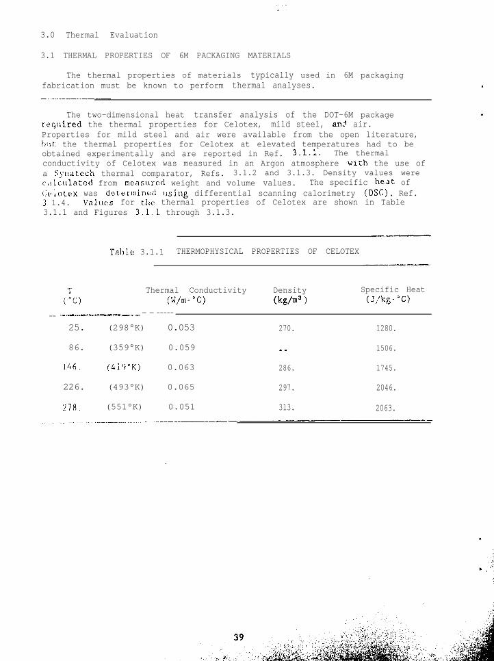
3.1 THERMAL PROPERTIES OF 6M PACKAGING MATERIALS
The thermal properties of materials typically used in 6M packagingfabrication must be known to perform thermal analyses.
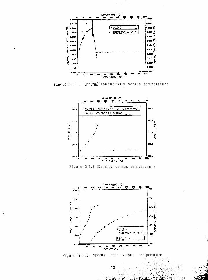
The two-dimensional heat transfer analysis of the DOT-6M packagereqtiired the thermal properties for Celotex, mild steel, an? air.Properties for mild steel and air were available from the open literature,bllt: the thermal properties for Celotex at elevated temperatures had to beobtained experimentally and are reported in Ref. 3.1.1. The thermalconductivity of Celotex was measured in an Argon atmosphere wrth the use ofa Synatech thermal comparator, Refs. 3.1.2 and 3.1.3. Density values werec;llc\llated from mensurcd weight and volume values. The specific heat ofi:~iotex was determine<! [ising differential scanning calorimetry (DSC), Ref.3 1.4. V‘lllIC?S for tllc: thermal properties of Celotex are shown in Table3.1.1 and Figures 3.1.1 through 3.1.3.
-----
Table 3.1.1 THERMOPHYSICAL PROPERTIES OF CELOTEX__---.
1’ Thermal Conductivity Density Specific Heat("C) (W/m-'(Z) (kg/m3 > (J,'kg-"C)
__ ..__ -..--..--_---- .---. - - -----
25. (298°K) 0.053 270. 1280.
86. (359°K) 0.059 we 1506.
IAh. (4i3"K) 0.063 286. 1745.
226. (493°K) 0.065 297. 2046.
278. (551°K) 0.051 313. 2063.
Lcra.m i ;
km?5 :0.m -
to.ws ;0.m -o.ola0.m 1
~0.0470
‘0.04s i
Fig\lr<n 3 . 1 i I’hcrmal conductivity versus temperature
Figure 3.1.2 Density versus temperature
Figure 3.1.3 Specific heat versus temperature ,,
3.0 Thermal Evaluation
3.1.1 REFERENCES FOR MODULE 3.1
The references for Module 3.1 are included in this module.,
References - Module 3.1
3.1.1 Sanchez, L. C., Longenbaugh, R. S., Moss, M., Haseman, G. M., Fowler,W. E., Roth, E. P., Thermal Analysis of the lo-Gallon and the 55-Gallon 6M Containers With Thermal Boundary Conditions Correspondingto lOCFR71 Normal Transport and Accident Conditions, SAND87-1896,TTC-0748, Sandia National Laboratories, Albuquerque, New Mexico,March 1988.
3.1.2 Moss, M., Koski, j, A., Haseman, G. M., Measurements of ThermalConCuctivity by the Comparative Method, SAND82-0109, Sandia NationalLaboratories, Albuquerque, NM, March 1982.
3.1.3 Sweet, J. N., et al., Comparative Thermal Conductivity Measurementsat Sandia National Laboratories, SAND86-0840, Sandia National!aboratories, Albuquerque, NM, June 1986.
3.1.4 Callanan, J.E., Sullivan, S. A., Development of Standard OperatingProcedures for Differential Scanning Calorimeters, Review ofScientific Instruments, Vol. 57, No. 10, October, 1986, pgs 2585-2592.
.
*- * . . .
This page left intentionally blank.
3.0 Thermal Evaluation
3 ? TIIERMAL ANALYSIS METHODOLOGY
The thermal model used to analyze the DOT-6M package for the normalenvironment and transport accident conditions has boundary conditions thatare in accordance with the regulations of MC's 10 CFR 71.
.
Three modes of energy transfer were used in this analysis:
1 Conduction heat transfer with the solid regions of the 6M package,
.
2. natural convection from the surfaces of the 6M containers to still airin t-he environment, and
‘? t.hcrmnl radiation hctween the surfaces of the 6M packages and theen5 1 ronmc~rrt
Thermal phases and boundary conditions are in accordance with the NRC'sregulations, 10 CFR 71, Kef 3.2.1, and can be observed in Tables 3.2.1 and7.2.2 in module 3.2.1, for the normal conditions of transport and forhypothcticn1 accident scenarios, respectively. These values were applied tothe mesh models for the lo-gallon and the 55-gallon 6M containers as shownin Figure 2.10.1. Thermophysical properties for the materials used in the 6Mpackages are given in Module 3.1, and more discussion of the steps used tomodel the packages can he found in Ref. 3.2.2.
References - Module 3.2.1
3.7.1 Packaging and Transportation of Radioactive Material, U. S. NuclearRegulatory Commission, Title 10, Code of Federal Regulations, Part71, 1987.
3.2.2 Sanchez, I,. C., Longenbaugh, R. S., Moss, M., Haseman, G. M., Fowler,W. E., Roth, E. I'., Thermal Analysis of the lo-Gallon and the 55-Gallon 6M Containers With Thermal Boundary Conditions CorrespondingI.0 10 CI'R 71 Normill Transport and Accident Conditions, SAND87-1896,?"SC-0748, Sandia National Laboratories, Albuquerque, New Mesico,March 1988.
3.2.3 Shippers--General Kequirements for Shipments and Packagings, USDepartmcn~ of Transportation, Title 49, Code of Federal Regulations,Part 173./415.
Table 3.2.1 DESCRIPTION OF PARAMETERS FOR NORMAL TRANSPORT CONDITIONS*
&nd. IIh;t~.t.:; t per todic, every 24 hours)(I) Twelv~*-tlc~~~~. hvnt up period when solar fnaolatfon fmpfngcs upon the!
packnl;e iti nn environment of ambient temperature of 38'C (100°F) Instill ail ;;ith insolation according to the following:
Form and js(:attion of surface Total insolation for a LZ-hour Deriod
*Required I-h~:smnl phases and boundary conditions are those of 10 CFR 71,Ref. 3.2.1. Environment emissivity and surface absorptivity values werechosen t:o coincide with required values for the hypothetical accidentscenario (see Table 3.2.2). Incident solar insolation is assumed to be
*,,totalLy absorbed.Convection heat transfer is modeled within the heat transfer code Q/TRANin a manner similar to this expression but incorporates a varying boundarylayer thickness for the natural convection phenomena.
TValue required in Ref. 3.2.3.
.
3.0 Thermal Evaluation
3.2.1 THERMAL ANALYSIS METHODOLOGY (Continued)
Table 3.2.2, Description of Parameters for Hypothetical AccidentScenario, is contained in this module.
b .
., ., :
:
.
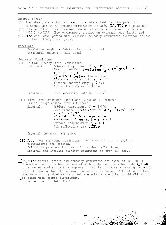
Table 3.2.2 DESCRIPTION OF PARAMETERS FOR HYPOTHETICAL ACCIDENT SCENAhIO*
Thermal Phases(I) The steady-state initial conditi.Is where heat is dissipated to
external air at an ambient temperature of 38°C (lOO"F)(no insolation),(II) the engulfing fire transient where radiation and convection from an
800°C (1472°F) fire environment provide an external heat input, and(1II)the cool down period with external boundary conditions identical to the
initial steady-state phase,
MaterialsInsulation region - Celotex industrial boardStructural regions - mild steel
External: Ambient temperature T - JE"CHeat transfer coefficaent ae -T - T (K)
h a 01s'4(W/m2
TS - l&al gurface temperatureEzvironment emissivity c - 0.9Surface absorptivity a 2 0.8All reflections are dr-2 fuse
Internal: Heat generation rate Q - 10 Wt
(II) Fire Test Transient Conditions--Duration 30 MinutesInitial temperatures from (I) aboveExternal: Ambient temperature T - 800°C
Heat transfer Coefficaent ha Cc B S 1'4(W/m2e -TTS
- T (K)- lgcal Zurface "emperature
Eavironmental emissi\,ity e - 0.9Surface absorptivity a - a.8All reflections are di?fuse
Internal: As shown (I) above
K)
K)
(1II)Cool Down Transient Conditions --Duration: Until peak payloadtemperatures are reached.Initial temperature from end of transient (II) aboveExternal and internal boundary conditions as from (I) above
.zRequired thermal phases and boundary conditions are those of 10 CFR 71.Convection heat transfer is modeled within the heat transfer code Q/T&Nin a manner similar to this expression but incorporates a varying boundarylayer thickness for the natural convection phenomena. Natural convectionphenomena for hypothetical accident scenario is specified in 10 CFR 71 tobe added when deemed significant.
TValue required in Ref. 3.2.3.
3.0 Thermal Evaluation
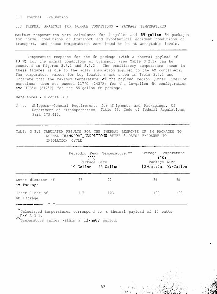
3.3 THERMAL ANALYSIS FOR NORMAL CONDITIONS - PACKAGE TEMPERATURES
Maximum temperatures were calculated for lo-gallon and 55-gallon 6M packagesfor normal conditions of transport and hypothetical accident conditions oftransport, and these temperatures were found to be at acceptable levels.
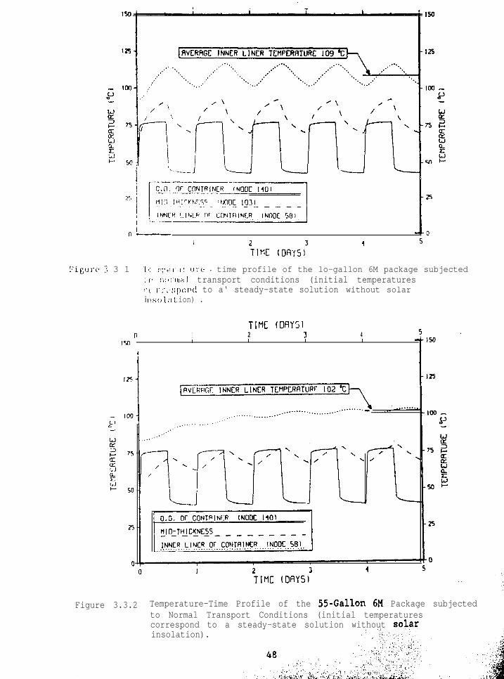
Temperature response for the 6M package (with a thermal payload of10 W) for the normal conditions of transport (see Table 3.2.1) can beobserved in Figures 3.3.1 and 3.3.2. The oscillatory temperature shown inthese figures is due to the solar insolation applied to the 6M containers.The temperature values for key locations are shown in Table 3.3.1 andindicate that the maximum temperature OF' the payload region (inner liner ofcontainer) does not exceed 117°C (243°F) for the lo-gallon 6M configurationand 103°C (217°F) for the 55-gallon 6M package.
References - blodule 3.3
3.3.1 Shippers--General Requirements for Shipments and Packagings. USDepartment of 'Transportation, Title 49, Code of Federal Regulations,Part 173.415.
Table 3.3.1 TABULATED RESULTS FOR THE THERMAL RESPONSE OF 6M PACKAGES TONORMAL TRANSPORT,CONDITIONS AFTER 5 DAYS' EXPOSURE TOINSOLATION CYCLE
Periodic Peak Temperature:** Average Temperature("Cl ("Cl
Calculated temperatures correspond to a thermal payload of 10 watts,..Ref 3.3.1.
Temperature varies within a 12-hour period.
.
.
I
i;,c,
1,!
i:igui-e 3 3 1 .I'< I:I\~~!~',I! 1.11.e .. time profile of the lo-gallon 6M package subjected: ,' I;OI.III;I~ transport conditions (initial temperatures
insolation).
I” ---I I 2
TIME (DRYS~'4
iyi I-I-,~:;IIo~~~\ to a‘ steady-state solution without solari ~!sc,l.at ion) .
TIME: (OAY’;In I 2 3 4
Is0 1 L 6 L
Figure 3.3.2 Temperature-Time Profile of the 55-Gallon 6M Package subjectedto Normal Transport Conditions (initial temperatures '(;+correspond to a steady-state solution without solar
1'si‘
3.0 Thermal Evaluation
3.4 THERMAL ANALYSIS FOR NORMAL CONDITIONS - PACKAGE INTERNAL PRESSURES
Maximum internal pressures for normal conditions of transport are afunction of maximum package internal temperatures. .
The sealed 2F. containment vessel of the 6M package may becomepressurized due to the heating of the containment vessel under normalconditions of transport. This thermal environment was evaluated in Module3.3. For normal transport, the maximum internal temperature inside thecontainment vessel is 117°C (2/+3"F) due to the lo-watt internal heat sourceand solar insolation acting upon a lo-gallon 6M. The total pressure withinthe containment vessel will be the sum of the partial pressures of theheated entrapped air, the vapor pressure of any water in the system or theradioactive material form, and the decompositicn gases of any of the organicpackaging materials. The material form must be dry and packaged in a dryair environment. Further, this analysis assumes negligible decomposition oforganic materials.
.
Therefore, the pressure generated by heating the entrapped air in the2R containment vessel is given by
P air - 14.7 x 1243 + 460) - 19.4 psia (4.8 psig)(70 + 460)
The pressure of the entrapped air is assumed to be the major componentof the maximum normal operating pressure (MNOP) of the containment in normaltransport.
It should be noted that the imposition of the assctmption that thematerial form is dry and that there is no organic decomposition of theorganic materials in the packaging is, in effect, placing a restriction onthe material form and the packaging materials in the 6M. Procedural stepsshould be implemented that reinforce these requirements. (See modules inSection 7.0).
This page left intentionally blank.
-.v: i
3.0 Thermal Evaluation
3.5 THERMAL ANALYSIS FOR NORMAL CONDITIONS - THERMAL STRESSES
Maximum thermal stresses due to normal conditions of transport lie wellwithin the allowable thermal stresses of the containment vessel.
The thermal stresses in the 2R containment vessel are a function of thetemperature gradient through the wall of the vessel. An analysis of thetemperatures on the inside and the outside of the containment vessel wallwas made for the lo-gallon and the 55-gallon 6M geometry. There wasessentially a negligible (less than O.l*C) temperature gradient through the0.25-inch wall thickness of the containment vessel, which in turn indicatesthere is essentially no thermal stress in the containment vessel wall underthe thermal environment imposed by the normal conditions of transport.
.
.
This page left intentionally blank.
.:.
1
3.0 Thermal Evaluation
3.6 THERMAL ANALYSIS FOR ACCIDENT CONDITIONS - PACKAGE TEMPERATURES
Maximum temperatures have been determined for the lo-gallon and 55-gallon 6M packages for hypothetical accident conditions, and thesetemperature magnitudes indicate that the thermal response of the packages toaccident conditions is acceptable.
The temperature respcnse for 6M packages exposed to hypotheticalaccident conditions is presented in Table 3.6.1. These results indicate thefollowing:
1. The maximum inner liner temperature for the lo-gallon 6M package(at Node 58) resulting from the simulation of accident thermalconditions is 120°C (248°F).
2. The Celotex material region will have a 2- to 3-cm thickness thatwill char [that is, the temperature in this region will exceed thechar temperature of 250°C (482°F) to 300°C (572"F), see Ref.3.6.11.
3. The maximum inner liner temperature for the 55-gallon 6M package(at Node 58) resulting from the simulation of accident conditionsis 95°C (203°F).
4. The Celotex material region will have a 2- to 3-cm thickness thatwill char (see Ref. 3.6.1).
References for Moduie 3.6
3.6.1 Sanchez, L. C.. Longenbaugh, R. S., Moss, M., Haseman, G. M., Fowler,W. E., Roth, E. P., Thermal Analysis of the lo-Gallon and the 55-Gallon 6M Containers With Thermal Boundary Conditions Correspondingto 10 CFR 71 Normal Transport and Accident Conditions, SAND87-1896,TTC-0748, Sandia National Laboratories, Albuquerque, New Mexico,March 1988.
.
3.6.2 Shippers-General Requirements for Shipments and Packagings, USDepartment of Transportation, Title 49, Code of Federal Regulations,Part 173.415.
‘,.
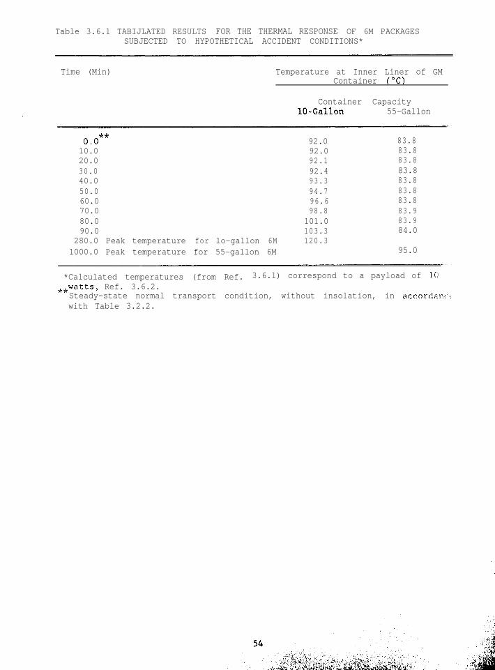
Table 3.6.1 TABIJLATED RESULTS FOR THE THERMAL RESPONSE OF 6M PACKAGESSUBJECTED TO HYPOTHETICAL ACCIDENT CONDITIONS*
Time (Min) Temperature at Inner Liner of GMContainer ("C)
280.0 Peak temperature for lo-gallon 6M 120.31000.0 Peak temperature for 55-gallon 6M
83.883.883.883.883.883.883.883.983.984.0
95.0
*Calculated temperatures (from Ref. 3.6.1) correspond to a payload of 10**watts, Ref. 3.6.2.
Steady-state normal transport condition, without insolation, in accordant.!with Table 3.2.2.
3.0 Thermal Evaluation
3.7 THERMAL TESTING FOR ACCIDENT CONDITIONS
Maximum and minimum temperatures have been recorded in the thermaltesting of 6M packages, and these temperatures lie well within the operatingrange of the 2R containment vessel.
.
The thermal tests which represent the thermal environment of theaccident conditions of transport were conducted in a 275-kilowatt inductionfurnace (Ref. 3.7.1) preheated to 830°C (1525°F) before to the 30-minutetest runs at 800°C (1475°F).
The test specimen was a 30-gallon 6M, instrumented with thermocouplesto continuously record interior temperatures during the test. The testresults are shown in Figure 3.7.1. The outer surface of the containmentvessel reached a peak temperature of 95°C (205°F). The peak temperatureoccurred about 2 hours after the start of the test and represents a rise ofabout 57°C (135°F) above that at the start of the test. Ref. 3.7.2 reportsan addItiona set of thermal tests on a lo-gallon 6-M. The package wasplaced in a prc-heated induction furnace and exposed to the thermalenvironment for 30 minutes. The thermocouples shorted out during the first5 minutes of exposure and the internal temperatures could not be monitoreddirectly. Temperature-sensitive pellets were placed in cans.in thecontainment vessel and on the exterior of the containment vessel. The 93°C(200°F) pellets on the side and bottom of the containment vessel showed 93°C(200°F) had just been recorded. The pellets on the cans in the containmentindicated that 65°C (150°F) had been exceeded but 79°C (175°F) had not beenreached. There was no scorching of paint on the radiation label and noswelling of the tin cans in the containment vessel.
The magnitudes of these observed temperatures on the 2R containmentvessel are less than the 149°C (300'F) which is required for maintaining thegasket seal capability in the containment vessel.
References - Module 3.7
3.7.1 Adcock, F. E., McCarthy, J. D., Wackier, W. F., Rocky Flats Model2030-l Container, (AEC-AL USA/5332/BLF), (SARP), RFP.1867, Rev. 1,February 27, 1974.
3.7.2 Adcock, F. E., Wackier, W. F., RFD Container, Model 1518 for FissileClass II and Class III Shipments, RFP-1042, The Dow Chemical Co.,Rocky Flats Div. Golden, Colorado, 1968.
Time-Temperature Data Recorded from Thermocouple Stations During Thermal
WDC * I 1 I I. ---------a- 1475OF (8OO'C)
14m -
e'----‘(- Solid lines are from three thermocouple
./ I stations in test of Model 2030-l package.rm
- i
/0: --- Curves with dashed lines are from
Ig lmo I
\/DrumModel 2040 tested under same conditions.
II tI 1
\\,l-l-in. Inside Celotex
2-in. Inside Celotex
205°F Max. Temperature@ flange of vessel
4
0 0.5 1.0 1.6 2.0
TIME (hours)
Figure 3.7.1 Time-temperature data recorded from thermocouple stationsduring thermal test runs (Ref. 3.7.2) on a 30-gallon 6M showthe 2R containment vessel is not over-heated.
3.0 Thermal Evaluation
3.8 THERMAL ANALYSIS FOR TRANSPORT ACCIDENT CONDITIONS - PACKAGE INTERNALPRESSURES
Maximum and minimum internal pressures for accident conditions occurat maximum and minimum internal temperatures for accident conditions,respectively, and lie within the design pressure limits of the 2Rcontainment vessel.
The internal heat generation region in the transjsllt analysis modelconsisted of the radioactive material within the containment vessel itself.The maximum temperatures reached at the inner liner of the 6M package was120.3"C (248°F) for the lo-gallon 6M. The maximum temperature reached atthe inner liner for the 55-gallon 6M was 95°C (203°F). The maximum pressureof the air entrapped in the 2R containment vessel can be calculated asfollows.
P air - 14.7 x (248 + 460) - 19.6 psia (4.9 psig)(70 + 460)
The pressure of the air entrapped in the containment vessel (4.9 psig)is well within the structural capabilities of the vessel,
.
This page left intentionally blank
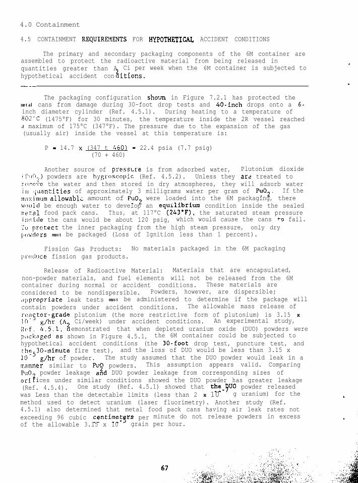
4.0 Containment
4.1 TYPES OF RADIOACTIVE MATERIALS AUTHOKKZED FOR 6M PACKAGINGS
The 6M packaging is authorized to contain Type B quantities of fissileand other radioactive materials in solid form.
The solid materials placed in the 6M are normal or special form*, andrange from metal or ceramic shapes (e.g., buttons, castings, fuel elements)to powders. The radioactive de.ay heat from these materials cannot exceed10 watts.
Only stable materials that do not decompose, outgas, or reactchemically with the packaging material up to temperatures of 177°C (350°F)shor(ld be packaged in 6M containers. The authorized amount of fissilematerials allowed in the 6M container is discussed in appropriate sectionsof 49 CFR, the DOT regulations.
Dispersible powders require special packaging to provide propercontainment. A procedure for packaging dispersible powders is included inModules 7.2, 7.3, and 7.4. This procedure provides for double co;ltainmentof plutonium oxide powders under hypothetical accident conditions.
*For definition if special form, see 49 CFR Part 173.403(Z).
This page left intentionally blank.
4.0 Containment
Lt.? DESIGN AND PERFORMANCE OF PRIMARY AND SECONDARY CONTAINMENT SYSTEM
The containment system (2R containment vessel and sealed metal foodpack cans) of the 6M packaging provides containment for authorizedradioactive materials in compliance with regulatory requirements,
Containment Boundary
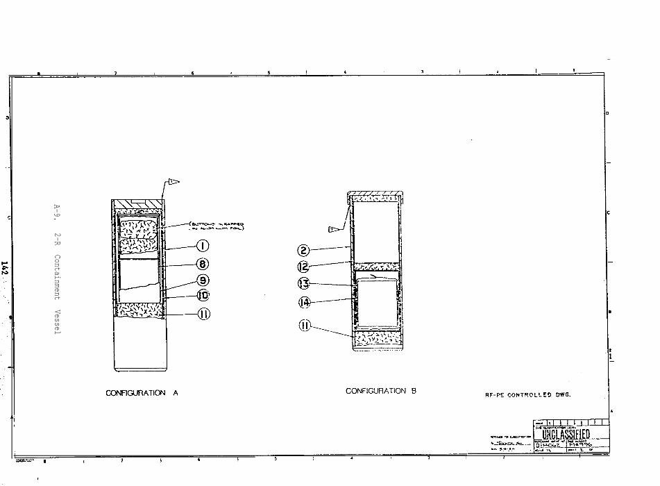
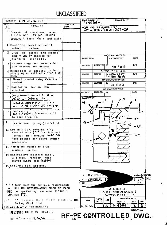
The principal containment boundary for the 6M packaging is the 2Rcontainment vessel, Figure 4.2.1 (see Module 4.2.1). Secondary containmentis provided in most cases by sealed food pack cans. All radioactivematerials other than special form materials or clad fuel elements must bepackaged in one or more secondary containers. When properly sealed 2Rcontainment vessels and metal cans are used, double containment is achieved,even for materials in powder form.
Containment Vessel
The 2R containment vessel, which is considered the primarycontainment, has been subjected to temperatures of 16o:Cpressures of 100 psig without leaking greater than 10
(320°F) andatm-cm /s. The food
pack cans, when properly sealed, can be heated to l!z°C (350Z,F) andpressurized to 15 psig and not leak greater than 10 atm-cm /s (Refs.4.2.1, 4.2.2). The seal on a properly sealed food pack can has also beenteste-!I usingx 10
3 helium leak detection technique and found to leak less than 5atm-cm /s of helium gas at 24°C (75°F). The leak rates for the 2R
vessel and the food pack cans are sufficiently low to preradioactive materials in excess of the allowable A,, x 10 -Fs ent releases of
curies per hourunder normal conditions and A(Ref. 4.2.2). 2 curies per week under accident conditions
Containment Penetrations
No penetrations such as valves or plugs exist in the 2R containmentvessel or the food pack cans.
Seals and Welds
The 2R vessel is sealed by applying a silicone rubber compound (G.E.Silicone Hi-Temp Gasket Material, GEC56002). The silicone rubber has atemperature range of -62°C (-80°F) to 260°C (500°F).
The food pack cai1.s are mechanically sealed using a sealing machine.The sealing operation squeezes a butyl rubber material applied to the canlid into the space between the metal folds.
The 2R vessel has a butt-welded plate on one end. The welds are madein accordance with the A.W.S. D1.l welding code, and are examined using adye penetrant procedure and/or radiography.
The side seam of the food pack can is crimped and soldered, or weldedafter crimping. The welding or soldering operation conforms to the FederalSpecification PPP-C-96D.
Closure
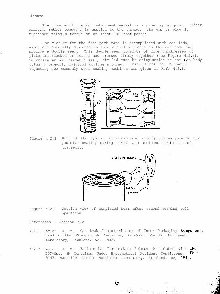
The closure of the 2R containment vessel is a pipe cap or plug. Aftersilicone rubber compound is applied to the threads, the cap or plug istightened using a torque of at least 100 foot-pounds.
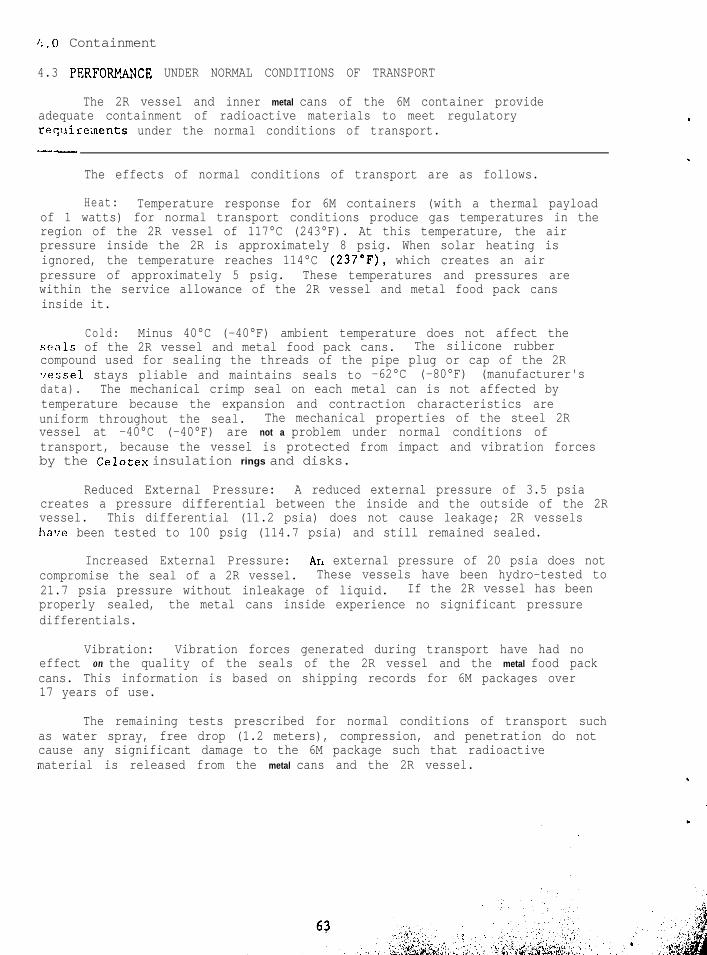
The closure for the food pack cans is accomplished with can lids,which are specially designed to fold around a flange on the can body andproduce a double seam. This double seam consists of five thicknesses ofplate interlocked or folded and pressed firmly together (see Figure 4.2.2).To obtain an air hermetic seal, the lid must be crimp-sealed to the c:nn bodyusing a properly adjusted sealing machine. Instructions for properlyadjusting two commonly used sealing machines are given in Ref. 4.2.1.
Figure 4.2.1 Both of the typical 2R containment configurations provide forpositive sealing during normal and accident conditions oftransport.
Figure 4.2.2 Section view of completed seam after second seaming rolloperation.
References - Section 4.2
4.2.1 Taylor, J. M. Gas Leak Characteristics of Inner Packaging Componellt-sUsed in the DOT-Spec 6M Container, PNL-5591, Pacific NorthwestLaboratory, Richland, WA, 1985.
.4.2.2 Taylor, J. M. Radioactive Particulate Release Associated with :he
4.3 PERFORNANCE UNDER NORMAL CONDITIONS OF TRANSPORT
The 2R vessel and inner metal cans of the 6M container provideadequate containment of radioactive materials to meet regulatoryrequireinents under the normal conditions of transport.---
The effects of normal conditions of transport are as follows.
Heat: Temperature response for 6M containers (with a thermal payloadof 1 watts) for normal transport conditions produce gas temperatures in theregion of the 2R vessel of 117°C (243°F). At this temperature, the airpressure inside the 2R is approximately 8 psig. When solar heating isignored, the temperature reaches 114°C (237"F), which creates an airpressure of approximately 5 psig. These temperatures and pressures arewithin the service allowance of the 2R vessel and metal food pack cansinside it.
Cold: Minus 40°C (-40°F) ambient temperature does not affect theseals of the 2R vessel and metal food pack cans. The silicone rubbercompound used for sealing the threads of the pipe plug or cap of the 2R-ressel stays pliable and maintains seals to -62°C (-80°F) (manufacturer'sdata). The mechanical crimp seal on each metal can is not affected bytemperature because the expansion and contraction characteristics areuniform throughout the seal. The mechanical properties of the steel 2Rvessel at -40°C (-40°F) are not a problem under normal conditions oftransport, because the vessel is protected from impact and vibration forcesby the insulation rings and disks.
Reduced External Pressure: A reduced external pressure of 3.5 psiacreates a pressure differential between the inside and the outside of the 2Rvessel. This differential (11.2 psia) does not cause leakage; 2R vesselshave been tested to 100 psig (114.7 psia) and still remained sealed.
Increased External Pressure: Arr external pressure of 20 psia does notcompromise the seal of a 2R vessel. These vessels have been hydro-tested to21.7 psia pressure without inleakage of liquid. If the 2R vessel has beenproperly sealed, the metal cans inside experience no significant pressuredifferentials.
Vibration: Vibration forces generated during transport have had noeffect on the quality of the seals of the 2R vessel and the metal food packcans. This information is based on shipping records for 6M packages over17 years of use.
The remaining tests prescribed for normal conditions of transport suchas water spray, free drop (1.2 meters), compression, and penetration do notcause any significant damage to the 6M package such that radioactivematerial is released from the metal cans and the 2R vessel.
Release of Radioactive Material: The maximum leakage of helium from asealed metal can has been measyred at 4.8 x 10 atmosphere. cubiccentimeters per second (atm-cm./s) at 2l'C (70°F). The ait &;ek rate from asealed metal can under normal conditions of transport with no_golar heqting(117'C (243"F), approximately 5 psig] is approximately 3 x 10 atm-cm /s.Whey solar 9eating is considered, the air leak rate is approximately 4 x10 atm-cm /s.
A gas leak rate of 10 -7 atm-crn3/s (dry air at 25'C)(5 x 10 -8 3cm /sleak test sensitivity) is considered to be leaktight (ANSI Standard N14.5).Double containment of plutonium powders can be made by using more than onesealed metal can to accomodate each quantity of plutonium and placing thecans in a 2R containment vessel which is then sealed.
10e8 cm ,/sTgsts have shown that ri leak rate test with a sensitivity of 5 x
is not necessary to determine particle leaktightness under normalconditions of transport. The maximum permissible mass release undernormal conditions for plutonium dioxide (Pu02) powder is 4 x 10
rgtegrams per
hour.
A test was conducted with depleted uranium dioxide (U02) powder (Ref.6.3.1) placed in food pack cans inside a 2R vessel in a 6M. The outer-mostfood pack can (the first sealed barrier) was bubble tested and showed noleakage. The bubble test was done ugder3field conditions and had a gas leakrate sensitivity of no more than 10 cm /s. After the 6M drum was dropped30 feet on an unyielding target and 40 inches onto a 6-ir.ch steel cylinder(puncture probe), the 2R vessel was removed from the 6M drum and placed in ntube furnace. The tube furnace was heated above 190°C (375°F) for 2 hours,then rotated (at 2 rpm) and vibrated (120 hertz, 0.6 to 0.8 g) for 6 hours,heat-up-and-soak time (6 hours).
The 2R vessel was then removed from the furnace and allowed to aircool. Using a procedure outlined in Ref. 4.3.1, the vessel was sampled 4days later to determine if any U02 powder had leaked from the No. 3 can. NoU02 powder was defected. The detection level of the analytical method wasless than 2 x 10 g uranium. The test showed that under conditions moresevere than what would be expected during normal cond4tions of transport,the release rate for the powder was less than 2 x 10 g/hr .
Consequently, a leakage test that has the sensitivity of 10 -3 3cm /s is
adequate to determine particle leaktightness for the metal cans used tocontain radioactive material.
References - Section 4.3
4.3.1 Taylor, J. M. Radioactive Particulate Release Associated with theDOT-Spec. 6M Container Under Hypothetical Accident Conditions, PNL-5747, Battelle Pacific Northwest Laboratory, Richland, Washington,1986.
64
4.0 Containment
4.4 PRESSURIZATION OF THE CONTAINMENT VESSEL UNDER NORMAL CONDITIONS OFTRANSPORT
The pressurization of the 2R vessel and metal food pack cans undernormal conditions of transport does not cause leakace in excess of Iregulatory requirements.
.
The pressure buildup inside the 2R containment vessel and the metalfood pack cans results from the expansion of the gas atmosphere confinedwithin these containers. Packaging materials such as treated vermiculite,silicone rubber, and plastics do not outgas significantly at temperatures upto 177°C (350°F) to contribute to package pressure,
Tests were conducted to determine the degradation and outgassing ofpolyethylene plastics, polyvinyl chloride plastics, and Celotex up totemperatures of 177°C (350°F). The materials were placed in a containerthat could be sealed, and the pressure was monitored during heating. [Thecontainer was first heated empty to 177°C (350"F), then it was loaded withthe plastics or Celotex.]
The amount of plastic loaded into the container was about 100 grams, atypical amount used to "bag out" material from a glove box into a metal can.When the materials were heated to 177°C (350"F), the pressure did notincrease above that observed when the container was heated empty tc the sametemperature.
Eighty-five grams of silicone rubber also were heated to 177°C (350°F)in the container: a small pressure increase of between 2 and 3 psi above thepressure from the axp:nsion of the air was observed. This total amcunt ofpressure would not debLade the seals of the metal cans.
Radioactive materials loaded into the 6M packaging must be stable upto 177°C (350"F), so they do not cause pressurization if they have beenproperly prepared.
A possible source of pressure buildup could be vaporization of thewater absorbed by hygroscopic powders. Pressurization due to steamgeneration from absorbed water during the heating of the 2R vessel isconsidered in Module 4.5. For the present discussion, i!. is assumed thepowders are dry when packaged.
The expansion of the gas (usually air) inside the 2R vessel and metalcans is caused by the decay heat of the radioactive material inside th!insulated 6M package. Under normal conditions (with no solar heating effectc:onsidered), with 21°C (70°F) ambient temperature and maximum internal heatgeneration from the radioactive material, the peak temperature within the 2Ris 114°C (237°F). The pressure of the gas is:
Neither pressure would degrade the seals of the metal food pack cansL or the 2R containment vessel.
Coolant Contamination: The air inside the 2R vessel and food packcans would be considered a coolant because it acts as a heat-transfermedium. The air itself does not become contaminated, and no radioactive. gases are generated by the types of materials packaged in the 6M container.Consequently, coolant contamination would not occur.
. Cooiant Loss: The 2R vessel and metal cans ere closed containers thatdo not have vents or pressure-relief devices. Venting could only occurthrough the sealed threaded surfaces of the 2R and through the crimpedlayers of the metal cans. The sealed 2R vessels are bubble tested beforefirst use and on a periodic basis-Tfte5 first use. This test has shown that.the gas leak rate is less than 10 cm /s. The sealed metal cans have beentested for leakage by using a helLurn mass spectrometer. After the metalcans were sprayed with8helJum, the gas in-leakage was compared with acaliLrnted leak of 10 cm /s. The leak rates for the 2R vessel and metalcans are low enough to prevent loss of any air containing aerosols(powders).
4.0 Containment
4.5 CONTAINMENT REQUIREldENTS FOR HyPOTHETICAl, ACCIDENT CONDITIONS
The primary and secondary packaging components of the 6M container areassembled to protect the radioactive material from being released inquantities greater than Ahypothetical accident con itions.?l
Ci per week when the 6M container is subjected to
--_--
The packaging configuration sho:m in Figure 7.2.1 has protected themetal cans from damage during 30-foot drop tests and 40-inch drops onto a 6-inch diameter cylinder (Ref. 4.5.1). During heating to a temperature of802°C (1475°F) for 30 minutes, the temperature inside the 2R vessel reacheda maximum of 175°C (347°F). The pressure due to the expansion of the gas(usually air) inside the vessel at this temperature is:
P - 14.7 x (347 t 460) - 22.4 psia (7.7 psig)(70 + 460)
Another source of pressure is from adsorbed water, Plutonium dioxidei?l~rt~) powders are hyeroscopic (Ref. 4.5.2). Unless they arz treated toriz~novc the water and then stored in dry atmospheres, they will adsorb waterjr, :iunntities of approximately 3 milligrams water per gram of Pu02. If them;iximmum allowable amount of Pu02 were loaded into the 6M packaging, therewr)uld be enough water to develop an equilibrium condition inside the sealedmeral food pack cans. Thus, at 117°C (243"F), the saturated steam pressureirlside the cans would be about 120 psig, which would cause the cans to fail.'To prctect the inner packaging from the high steam pressure, only dryi,oxders must be packaged (Loss of Ignition less than 1 percent).
Fission Gas Products: No materials packaged in the 6M packagingp~‘o(lucc fission gas products.
Release of Radioactive Material: Materials that are encapsulated,non-powder materials, and fuel elements will not be released from the 6Mcontainer during normal or accident conditions. These materials areconsidered to be nondispersible. Powders, however, are dispersible;,-ippropriate leak tests must be administered to determine if the package willcontain powders under accident conditions. The allowable mass release ofre?st.or-grade plutonium (the more restrictive form of plutonium) is 3.15 x
Alif. :/:fl(AiCi/week) under accident conditions. An experimental study,
emonstrated that when depleted uranium oxide (DUO) powders werepitckaged as shown in Figure 4.5.1, the 6M container could be subjected tohypothetical accident conditions (the 30-foot drop test, puncture test, andthe530-minute fire test), and the loss of DUO would be less than 3.15 xIO g/hr of powder. The study assumed that the DUO powder would leak in am‘anner similar to PuO powders. This assumption appears valid. ComparingPuO powder leakage aid DUO powder leakage from corresponding sizes ofori ices under similar conditions showed the DUO powder has greater leakageic(Ref. 4.5.4). One study (Ref. 4.5.1) showed that the-quo powder releasedwas Less than the detectable limits (less than 2 x 10 g uranium) for themethod used to detect uranium (laser fluorimetry). Another study (Ref.4.5.1) also determined that metal food pack cans having air leak rates notexceeding 96 cubic centimetTrs per minute do not release powders in excessof the allowable 3.15 x 10 grain per hour.
External
Figure 4.5.1 Packaging arrangement to protect metal food pack canscontaining plutonium dioxide inside the 2R contdinmentv e s s e l .
References - Module 4.5
4.5.1 Taylor, J. M. Radioactive Particulate Release Associated with theDOT-Spec 6M Container Under Hypothetical Accident Conditions. PNL-5747, Battelle Pacific Northwest Laboratory, Richland, Washington,1986.
4.5.2 Stakebako, J. L., and Dringman, M. R. Hygroscopicity of PlutoniumDioxide, RFP-1056, Dow Chemical Co., Rocky Flats Division, Golden,Colorado. 1968.
4.5.3 Sutter, S. L. et al., Depleted Uranium Dioxide Powder Flow ThroughVery Small Openings, NUREG/CR-1099, PNL-3177, Battelle PacificNorthwest Laboratory, Richland, Washington, 1980.
4.5.4 Yesso, J. D., et al., Study of Plutonium Oxide Powder Emissions fromSimulated Shipping Container Leaks, NUREG/CR-1302, PNL-3278, BattellePacific Northw::st LaborAtory, Richland, Washington, 1980.
5 . 0 S h i e l d i n g
5.1 SHIELDING REGULATIONS
When necessary, shielding may be provided within the 2R containmentvessel to reduce penetrating radiation in accordance with federal regulatoryrequirements,
The level of nonfixed (removable) radioactive contamination on theexternal surfaces of each package offere’d for shipment must be kept as lowas practicable. This level is specified in 49 CFR 173.443 and 10 CFR 71.78.These regulations also describe the method for assessing the amount ofexternal surface contamination.
Because packages containing radioactive materials (RAM) may be carriedon the same vehic1.e as passengers, a simple system was developed todetermine how many passengers could be loaded and how to segregate thepackages from passengers and film. This system is the radiation transportindex (TI) , which yields the highest dose rate at 1 meter (3.3 feet) fromany accessible external-surface of the RAM package measured in millirems perhour, rounded to the next highest tenth. The radiation level at any pointon the external surface of the package must not exceed 200 millirems perhour, and the TI may not exceed 10 except for packages shipped by exclusive-use vehicles.
When more than one package is loaded onto a transport vehicle, a totaltransport index is obtained by adding the TIs for each individual package.The total TI for a single vehicle or storage location generally may notexceed 50.
All packages must retain their shielding effectiveness during normaltransportation. The TI must not increase during transport as the result offaulty shielding, from shifting of the packages, or from the movement of theshielding in the packages.
Packages shipped by rail, highway, or water in exclusive-use closedtransport vehicles may not exceed the following radiation levels as providedin 49 CFR 173.441(b) and similar requirements in 10 CFR 71.47:
- One thousand millirem/hour on the external package surface.
- Two hundred millirem/hour at a point 2 meters (6.6 feet) from thevertical planes projected by the outer lateral surfaces of the caror vehicle; or, in the case of an open vehicle, at any point 2meters from the vertical planes projected from the outer edges ofthe vehicle.
- Two millirem/hour in any normally occupied position in the car orvehicle.
(This provision does not apply to private motor carriers when the personnelare operating under radiation protection and wear radiation-exposuremonitoring devices.)
Any package containing more than limited quantities of RAM must belabeled on two opposite sides with one of the three warning labels:“RADIOACTIVE WHITE I, I’ RADIOACTIVE YELLOW II ,” or “RADIOACTIVE YELLOW III”(49 CFR 173.421). Table 5.1.1 gives a summary of the RAM package labelc r i t e r i a .
69
I
.
.:i. .*
Table 5.1.1 RAM PAMAGE LABELING REQUIREMENTS ARE SPECIFIED BY DOTREGULATIONS.
Transport Radiation Level at Fissile LabelIndex (TI) Package Surface (RL) Criteria Category*
X/A 0.5 millirem/hour Fissile ClassI only, NoFissile ClassII or III
White I
1.0 0.5 millirem/hour Fissile Class I, Yellow IIFissile Class IIwith TI 1.0,No FissileClass III
1.0 50 millirem/hour Fissile Class II Yellow IIIwith TI 1.0,Fissile Class III
---.-~-*Any package containing a "Highway Route Controlled Quantity" (49 CFR173.403) must be labeled as Radioactive Yellow III, (DOT, 1983).
5 . 0 S h i e l d i n g
5.2 NON-SHIELDED 6M CONFIGLII~+.TTONS
Some AM designs are co.*L;gu , .?d such that the packaging componentsprovide sufficient shielding mater !nl to meet the regulatory requirementsfor surface radiation.
In order to prepare a general and conservative shielding analysis forthe 6M packaging, a single point source of Cobalt-60 with an activity equalto 1 curie was assumed to be located at the interior wall surface of the 2Rcontainment vessel. The point source is meant to be a generalized approachto evaluating the shielding properties of typical 6M packagings in thelimited sizes (limited in the sense of radial dimension) lo- and 55-gallondrums. In volume, the IlO-gallon drum is the largest size of the 6Mpackagings, but its diameter is the same as that of a 55-gallon drum.Actual surface dose retes can be determined by linearly extrapolating theresults from a l-Ci source, as shown in Table 5.2.1, to the specifiedactivity. The location of the source and the geometry of the shieldingdesign are shown in Figure 5.2.1.
The variables for the lo- and 55-gallon geometries are given in Table5 . 2 . 2 . The energy-dependent variables are shown in Table 5.2.1, and thsshielding analysis results for a 1-Ci source for the non-shielded version ofthe 6M are presented in Table 5.2.2.
For a single shield design the surface dose rate is given in thee q u a t i o n b e l o w : -Ust
t R shield thickness (centimeters)E- gamma energy (million electron volts - MeV)M- mass energy absorption coefficient
Q-(centimetgr per gram - cm/g)1.6 x 10 rad per MeV/g
IIiI ( 6 . 4 1 o m )L
i 2.7B In +
i(7.065 em)’
ii 6.0 InI (17.5s em).
‘rl
1
gal)
rodlur ( 5 5
Drs5
7 j.25 In
-1)
(2l3.58 c m ) ’
Figure 5.2.1 6M non-shielded design configuration shows the radioactivesource and shielding design geometry.
Table 5.2.1 GAMMA-SPECIFIC DATA FOR 6M NON-SLEEVED DESIGN ARE USED TOCALCULATE DOSE RATES.
GammaE us Bs M
(MeV) (cm-') (unitless) (cm2/g)
1 1.17 0.45 1.4 0.03
2 1.33 0.45 1.4 0.03
Table 5.2.2 THE SHIELDING ANALYSIS SUMMARY FOR THE LIMITING RADIAL SIZESOF 6~ PACKAGES SHOWS BASIC DOSE RATE DATA.
6M Drum Size(non-sleeved design)
Surface Dose Rate(millirads per hour)
10 gallons
55 gallons
7.8 x 10' .
2.1 x 10'
5.0 Shielding
5.3 SHIELDED GM CONFIGURATIONS
Some radioactive materials transported in 6M packages have sufficientsource term magnitude that it is necessary to install additional shieldingmaterial in the package in order to meet the regulatory requirements forsurface radiation.
Some 6M configurations may require additional shielding because of themagnitude of the Jctivity of the material being transported in the package.When this is the case, an additional amount of shielding may be instrtedinto the interior of the 2R containment vessel. Based upon material in Ref.5.3.1, the shielding for this type of geometry can be approximated by
DR - Surface Dose Rate = (S)(Bsl)(Bs2)e-'(US1)(t1) + (us2)(t2)14nr2
where Bsl and us1 are the gamma-specific data for the first or inner shield(depleted uranium) and !',s2 and us2 are the gamma-specific data for thesecond or outer shield (steel, the wall of the 2R containment vessel).
The geometric variables for the sleeved design are shown in Figure5.3.1, the energy-dependent variables in Table 5.3.1, end the surfaceradiation dose from a l-Ci source from the sleeved design in Table 5.3.2.As with the non-sleeved design, the results for the surface dose rate fromthe 1-Ci source can be linearly extrapolated to obtain the surface dose forthe magnitude of RAM being transported in a sleeved 6M package.
Table 5.3.1 THE DATA SHOWN ARE USED IN THE GENERIC SHIELDING CALCULATIONS
Table 5.3.2 THE GENERIC SHIELDING ANALYSIS CALCULATIONS ARE SHOWN FOR A1-Ci Co-60 SOURCE.
Drum SizeSurface Dose Rate
(mrad/hr)
10 gallons
55 gallons 4.1 x 10³
With s l e e v e/
.,..I ee”tO~ll,mrnt- - -
Figure 5.3.1. The 6M shielded-design configuration.
References - Module 5.3
5.3.1 Morgan, K. Z., Turner, J. E., Principles of Radiation Protection,R. E. Krieger, Publishing Co., 1973.
5.3.2 Jaeger, R. G., ed., Engineering Compendium on Radiation Shielding,Vol. I, Springer-Verlag, New York, 1968.
’k
74 i.
: ._.lj ' '- ., ._ : . :. 6 ' ‘I_*
6.0 Criticality
6.1 USE OF 6M FOR SHIPMENT OF FISSILE MATERIAL
The 6M packaging provides a satisfactory method of transporting severalfissile materials.
A 6M container of appropriate size may be selected for many fissilematerial transport applications. Detailed evaluations have been providedfor Uranium-235, Plutonium 239, and Uranium-233. Resulting allowableloadings and transport indexes (TIs) provide more economical transport thanpreviously authorized.
.
The tabulated mass values for Uranium-235 may be applied to anyenrichment. The lo-\latt thermal heat load restriction on the 6M results inmaxlmum loadings of approximately 20 grams of Plutonium-238 andapproximately 96 grams of Americium-241. Tabulated plutonium mass valuesmay be applied to Neptunium-237 in the absence of validated calculations forthis material.
This page left intentionally blank.
?
76.:; .‘., (,,.,?? ? ?
6.0 Criticality
6.2 TABULATED VALUES OF FISSILE CLASS I AND CLASS II LIMITS
The derived fissile material mass limits meet a wide variety ofpackaging and transportation needs.
The fissile materials of greatest interest to the DOE and itscontractors for shipment are enriched uranium and plutonium. An occasionalneed arises to transport Uranium-233. Fissile Class'1 package limits areprovided for these materials loaded in lo-, 15-, 30-, 55-, and ll@-gallonsizes of 6Ms (Table 6.2.1). Fissile Class II package limits provided forthe 30-gallon 6M are also applicable to the 55- and IlO-gallon si.zes (Table6.2.:).
The influence of fissile material density on allowable loadihlgs is acomplex function of container size, array size, an@ material density.Increased moisture content reduces the quantity of fissile material that maybe loaded in a container for a specified transport index, These influenceshave been accommodated in a detailed criticality evaluation (Ref. 6.2.1).
The evaluations performed on the 6M package covered a broad range offissile materials and forms for various packaging sizes. The analyses wereperformed to satisfy fissile material mass limit requirements for:
1. The single package safety analysis of lo-, 15-, 30-, 55-, and IlO-gallon6M packagings.
2. Fissile Class I packages (minimum Transport Index a 0.0) of the lo-,15-, 30-, 55., and IlO-gallon 6M packages as subcritical infinite arraysof undamaged and damaged packages.
3 . Fissile Class II packages (minimum Transport Index - 0.1, 0.5, 1.0, 5.0,and 10.0) of 30-gallon 6Ms; this information may be then applied to the55-gallon and IlO-gallon 6M sizes.
The criticality evaluation given in Ref. 6.2.1 provides an adequatebasis for the subcritical nature of 6M packagings. Additional margins ofsubcriticality have been introduced into the safety analysis by considering100 percent fissile isotopes. These circumstances plus other realconsiderations (such as less than theoretical material densities and lessreactive material compositions) provide substantial margins of safety forthe single package configuration, and to a lesser extent, for the arrayevaluations. It is concluded in Ref. 6.2.1 that the material mass limitsand conditions outlined in Table 6.2.1 for the use of 6M packagings meetspecific federal criticality safety regulations found in 10 CFR and 49 CFR.
References - Module 6.2
6 ,2 . ? Thomas J. T., and Hopper, C. M. Nuclear Criticality Safety Analysisfor the 6~ Specification Package, (Draft Report), ORNL-6176, OakRidge National Laboratory, Oak Ridge, Tennessee, August 1986.
Uranium containing more than 1 percent of U-233 shall be treated asU-233.
Uranium containing more than 1 percent of plutonium (Pu) shall betreated as plutonium.
When both the U-233 and the Pu content exceed 1 percent, the mostrestrictive limit shall apply.
The plutonium limits apply to any plutonium isotopic composition SO 10r1g
as the Pu-240 content exceeds the Pu-241 content.
The maximum internal heat load for any 6M package is 10 watts,
The maximum useable internal. diameter of the 2R containment vessel used
for U-233 shall be 4 inches.
Allowable loadings shall comply with all features of Table 6.2.1. For(example, a shipment of U02-235 at a density of 0.95 shall use theFissile Class I limit appropriate to an H/x of 10, even though theactual H/x is less than one.
Plutonium values in excess of 4.5 kg are provided for use with mixturesof uranium and plutonium not exceeding the lo-watt limitation,
The tabuiated mass values are for total uranium and plutonium withoutregard to isotopic content.
- --
78
6.0 Criticality
6.3 BASIS FOR TABULATED LOADING VALUES
The method of deriving the allowable loadings Eor the 6M has resultedin compliance with the criteria presented in the regulations oi the UnitedStates and the International Atomic Energy Agency.
Whill? puncture and drop tests result in some distortion of the outerdrum of the 6M, this small magnitude of deformation of the packaging has noinfluence on the allowable loadings. Array calculations have been based onthe closest possible stacking of the containers.
Exposure of the 6M to the thermal test representing hypotheticalaccident transport conditions results in charring of the outer portion ofthe Celotex insulating disks and rings. In the array calculations, thehydrogen and oxygen were removed from the outer 2-in-h region of theCclotex. This is consistent with the results of actual thermal tests.
Single-package eval*lations assumed full water reflection and waterinleakage to the 2R containment vessel, with the fissile materialdistributed in the most reactive concentration achievable, as determined byvalidated computational techniques.
The evaluation of single-package configurations and arrays of 6Mpackagings used broadly accepted calculation techniques. The specific codesused are common discrete coordinate and Monte Carlo computer programs. Allthe input parameters and processing techniques are part of the SCALE program(Ref 6.3.1), which is the preferred analytical approach of the NRC.
References - Module 6.3
6.3.1 SCALE: A Modular Code System for Performing Standardized ComputerAnalyses for Licensing Evaluation, NUREG/CR-0200, published 1982,revised June 1983. December 1984.
.
. .
This page left intentionally blank.
7.0 Operating Procedures
7.1 OPERATING PROCEDURES FOR 6M PACKAGINGS
The safety of 6M packagings used in support of DOE programs is assuredby strict observance of detailed operating procedures and inspections.
For 20 years the 6M container has served as one of the nation's primaryTYF" B packagings. During this period there has never been a seriousaccident or release of radioactive contents from a 6M package to theenvironment. This record is due partly to the design and partly to thecareful adherence to the operating procedures and inspections developed bythe users of these packagings.
.
Procedures for the following operations are included in Section 7,Operating Procedures:
Module Ooeration
7.2 General specifications and requirements for plutonium packagings
7.3 Packaging of plutonium material in fxd pack cans
7 .k Loading of the 2R containment vessel
7.5 Final assembly of the 6M pxkage
7.6 Unpacking procedures for the 6M package
This page left intentionally blank.
7.0 Operating Procedures
7.2 GENERAL SPECIFICATIONS AND REQUIREMENTS FOR PLUTONIUM PACKAGINGS
The following generic specifications are intended to apply to allplutonium packaging for shipment. More detailed requirements are given fordispersible materials in the following section. This set of specificationsis intended to call attention to the principal factors that need to becontrolled in the transport of plutonium material.
.
*The temperature expected to be achieved as a result of exposure to thehypothetical accident conditions, approximately 149°C (300'F).
The i.-ner packaging shall not degrade and shall remain intact whensubjected to the maximum temperature expected during normal shipment.Determination of thr maximum shall include: (1) heat from radioactive decay,chellli<al reactions within the package, and external heat sources,(2) evaluation of insulation or barriers to heat flow, and (3) evaluation ofthe package configuration tnside the insulated drum for the maximum credibletime.
Pressure within the food pack cans and 2R vessel shall not exceed thepressure that these components are subjected to during leak testing, (e.g.,bub'le testing at approximately 15 psig). Considerations relating to themaximum pressure shall include: (1) gas formation due to thermaldecomposition of the contents, (2) thermal expansion of the gases,(3) radiolytic gas generatlon, and (4) gas formation by chemical reactionswithin the package.
The outer surface of the sealed metal containment system shall be freeof radioactive contamination.
Each containment system (metal food pack can) shall be clearly anduniquely labeled. The label shall be leg!ble after being subjected tomaximum normally expected temperature and radiation dose for the maximumcredible time.
Eacil package or shipment shall include a complete listing of thecontents. The listing shall describe the material within each containmentsystem. If needed, special handling instructions for unpacking shall beincluded with th? packing list.
Solid plutonium compounds that are dispersible, sych as powders, andare stable in air at the credible shipping temperature shall be placed in ametal container (such as a taped slip-lid can), which is then placed in asealed polyethylene bag. This bag is placed inside a mechanically sealedfood pack can. Finally, the food pack can is placed inside anothermechanically sealed food pack can.
The compound must have a loss of ignition (LOI)* of less than 1 percentwhen heated in an inert atmosphere at 45O'C (842°F) for 2 hours. Compoundsthat react with air, such as carbides or hydrides, must be packaged in aninert atmosphere. Prior to shipment, the powders must be stored in a dryatmosphere (dew point, 21°C (70°F)) to prevent adsorption of water.
*LO1 is usually a measure of volatile components. Some chemical reactionscould result in weight gain on ignition, and if this is possible, a methodother than weight change must be used to determine volatile components.
1
2
3
4
5,
6.
7.0 Operating Procedures I .
7.3 PACKAGING OF PLUTONIUM MATERIAL IN FOOD PA& CANS
The packaging of plutonium materials in food pack cans according to thefollowing procedure will contain dispersible plutonium powders within theregulatory limit.
This procedure pertains to the operation of placing the plutoniummaterial in food pack cans before placing the cans in the 2R containmentvessel. At this stage of the operation, the plutonium has been placed in ametal container such as a taped, slip-lid can inside a glove box. The metalcontainer has been "bagged out", that is, placed in a polyethylene baginside the glove box and made ready for placement in the food pack can.
The food pack cans used to contain the plutonium material must conformto Federal Specification PPP-C-96D. The cans are classified as Type I,Class 3, packer's cans. Only ribbed reinforced lids (concentric rings)shall be used. The flat. profile (no rings) lids will permanently deform whenpressurized to 15 psig during bubble testing.
Packaging Procedures
.
Inspect can body and make certain it is not dented or damaged.
Inspect the flange on the can body. If the flange has been severelybent or creased, do not use it. Small creases can usually bestraightened by using long-nose pliers. Run your finger around theflange to make certain it is smooth and no discontinuities are prese;:t.Generally, there is a small ridge in the flange where the side seamintersects it, If the ridge is quite abrupt, smooth it off carefullywith a fine-toothed jewelers file or discard the can.
Inspect the lid and make sure the rim where the rubber compound has beenapplied is smooth and uniform. There should be no exposure of metalshowing through the rubber compound. If there are scratches or shinyspots (metal showing through), discard the lid. Also, make sure thecurl or roll-over at the rim of the lid is uniform and not dented.
Place the bagged container (polyethylene bag) in the food pack can (No.2 l/2 size) as shown in Figure 7.3.1. The silicone rubber spacers shownare about 0.5-inch thick. Do not force or stuff the bag into the foodpack cans.
Place the lid on the can and check to see that the lid is seatedproperly. The curl on the rim of the lid should be below the flange onthe can. Do not rotate the lid on the flange, or the rubber compoundmay be scratched or damaged.
Center the cans on a properly adjusted can sealer (see Appendix B ofRef. 7.3.1). Rotate the base plate,to make certain the can is centered.
a 5
7. Raise the can or lower the chuck depending on the sealer, making surethe lid to be sealed is properly engaged in the chuck. Position thecan so that the part of the lid directly over the side seam on the candoes not contact the seaming roller first.
8. Before cranking the handle of the sealer (mctorizcd can sealers returnto correct starting position automatically), make certain that theseaming rollers are in the proper starting position (see Ref. 7.3.1Appendix B, for discussion on properly setting up the sealer). Crankthe handle in the clockwise direction. Try to maintain a uniformrotation through the sealing operation. If a motorized can sealer isbeing used, only use one complete cycle to seal the cans. Repeatingthe the cycle will not provide better seals, but may degrade the firstsealing operation.
9 . Lower the turntable or raise the chuck, and remove the can. If the: canis stuck on the chuck, the second seaming roller is set too tight.
10. Visually esnmine the can for obvious defects as illustrated in Appendi:<B of Ref. 7.3.1. If defects are present, the can sealer is out ofadjustment and must be repaired.
E m p t y S l i p Lid C e n r4 l/4-in. d i e r . 1 7/E-in. h i g h i n s i d e3 l/2-in. dir x 1 3/6+x high
02 E m p t y S l i p L i d C a nC u t t o S i z e
4 l/4-in. die x 7-in. high Can( N o . 3 Size)
0 4 l/16-in. d i a x 4 11 /16-in. h i g h C a n(No. 2 l/2 Size1
2 R vesseI
C a n L i d S p a c e r s
3 l/2-in. die x 3 l/2-in. highS l i p L i d C a n9
9
10
1 1
I1 2
1 3
14
16
Pu01 P o w d e r
spacer Plate
V e r m i c u l i t e,
S tyro foam Spacer
Polyethylene Bag
PUOZ P o w d e r
S p a c e r
Tape seal
Figure 7.3.1 Packaging arrangement to protect metal cans containing PuO2inside 2R containment vessel.
References - Module 7.3
7.3.1 Taylor, J. M. Gas Leak Characteristics of Inner Packaging ComponentsUsed in the DOT-Spec 6M Container, PNL-5591, Battelle PacificNorthwest Laboratory, Richland, Washington, 1985.
86
7.0 Operating Procedures
7.4 LOADING OF THE 2R CONTAINMENT VESSEL
Leak tightness of the DOT-2R containment vessel is assured by properluting (sealing) and torquing of the vessel's cap or plug closure.
A visual inspection of the threads on the 2R containment vessel bodyand pipe cap or plug should be conducted prior to use. If the threads aredamaged continuously from the bottom of the thread to the top, then the partmust be rejected. The fit between the mating parts determines how well apipe assembly seals. Steps that should be taken in order to obtain a properseal are listed below.
.
1. Visually inspect the threads on the 2R containment vessel pipe body andpipe cap or plug. If the threads are damaged continuously from thebottom of the thread to the top, reject the part. Repair minor damageusing a thread dressing tool.
2. Stack the cans inside the containment vessel as shown in Figure 7.4.1.The impact-absorbing cans shown between the No. 3 cans are made bycutting a 4 l/4-inch-diameter x 5 9/16-inch-high slip-lid can. Theinner can shown can be made up from a 3 l/2-inch-dianeter x 3 l/2-inch-high slip-lid can. The inner can is centered inside the outer can withvermiculite. Spacer plates are required between the No. 3 cans and theimpact-absorbing cans so that the impact load will be transmitted to thesidewalls of the No. 3 cans. This will prevent the No. 3 cans fromdeforming during impact. The details of the spacer plates are shown inFigure 7.4.2. To prevent the can lids from becoming concave duringimpact, fill the space between the can lid and the spacer plate. Thiscan be done by forming a plug of a low-melting alloy such as bismuth-cadmium (60 percent Bi, 40 percent Cd), Melt the alloy and pour it ontothe lid of a sealed No. 3 can. Level the plug by drawing a straightedge across the top of the can. After the plug has solidified, removeit and file off enough material around the circumference so it fitseasily onto the lid of the can. The plug will conform to the shape ofthe can lid as shown in Figure 7.4.3. The plugs are easy to fabricateand are reusable.
3. Coat the threads on the containment vessel body and cap or plug with aliberal amount of G.E. Silicone Hi-Temp Gasket Material, or equivalentmaterial approved by DOE, and screw the plug or cap into or onto thecontainment vessel body until hand-tight.
4. Place the containment vessel in a vise or other holding device andsecure it so it will not slip.
5. Using a torque wrench with a pipe clamp or plug fixture, tarque the capor plug to 100 foot-pounds.
6. Wipe off the excess pipe compound. .
7. Bubble test* (see ANSI Standard N.14.5, Appendix A, A3.6, for bubble testprocedure). If no streaming bubbles are observed, the seal is adequate. .
*If G.E. Silicone Hi-Temp Gasket Material is used on the threads, allow 12to 14 hours for curing of the material before bubble testing the seal.
i.
,’
hptv SllP Cd Cans4 l/4.111 dm I 1 ~/&III tqh mrtde3 l/l.m. dtl, I 1 3/B-m hlgh
0Empty Shp Lid Cancut to Sua
@ 4 ,,a.,,~ da. 7.m h,ghCsn(NO 3 Slral
0 ,,,, 6 .,,, d,ar4 ,1/l&m.hlghCanINo 2 112 SlZeb
8 5 7
6 Can Lid Spncerr
2R 3 ,/2-,n Vosstl d,a I 3 112 an hophwp Lid Can
PUO, Powder
SPcal PIale
V.,lTlE”llle
Slrrotoam Spscsr
Polyelh”lenP Enp
P”0, Powder
SPtlCW
Taps Seal
Figure 7.4.1 The packaging arrangement Figure 7.4.2 Metal spacer platesfor the metal cans in the 2R are used to separatecontainment vessel is shown. the food product cans
from the spacercans.
Figure 7.4.3 Metal plugs are used to protect the can lids from impact forces.
8. If less than one kilogram of powder is packaged, the plugs do not have to beused.
References - Module 7.4
7.4.1 Taylor, J. M. Radioactive Particulate Release Associated with the DOT-6MContainer Under Hypothetical Accident Conditions, PNL-5747, PacificNorthwest Laboratory, Richland, Washington, 1986.
7.0 Operating Procedures
7.5 FINAL ASSEMBLY OF THE 6M PACKAGE
Package integrity is assured during final assembly according toverifiable procedures.
The final assembly of the 6M package consists of a number ofverification steps to ensure total compliance with the DOT regulations in 49CFR. Shown below is a checklist that will assist in complying with the DOTregulations.
1. Verify that the radioactive material to be shipped complies with DOTregulations.
- lL. Ensure that packaging of radioactive material is in a metal can or a
polyethylene bottle, if the material is not special form.
3. Inspect the 2R containment vessel for damaged threads or other defectsbefore placing the metal cans or polyethylene bottles into the vessel.
4. Verify that the threads on the vessel body and the cap or plug havebeen coated with a liberal amount of G.E. Sili...one Hi-Temp GasketMaterial.
5. Allow approximately 10 to 12 hours for the silicone sealing compound tocure before performing the leak testing. Ensure that the containmentvessel cap or plug has been torqued (see Table 7.5.1) and leak tested.
6. Visually check the drum, drum lid, lid* gasket, and locking ring(including lug welds) for defects.
7. Verify that the vent holes are functional.
8. Visually check the Celotex rings and disks for defects
9 . Place the 2R containment vessel into the cavity formed by the Celotexrings and disks, and assemble the remaining rings and disk(s).Packages over 480 pounds require steel or wood bearing plates.
10. Verify that the 2R containment vessel is flush below the surface of thetop Celotex ring to prevent gapping.
11. Verify a 0.5-inch gap (maximum) between the drum lid and the Celotexdisk. Fill the gap with non-combustible packing material.
12. Secure the locking ring with the proper bolt and locking nut. Torquethe locking ring bolt to the appropriate foot-pound level while tappingthe locking ring with a soft-head hammer. Verify that the ends of thelocking ring have not closed (come into contact with each other). (SeeTable 7.5.1 for bolt sizes and torque values.)
89
13. Check that the closure-ring bolt has been secured with a lock nut orequivalent device.
14 , Apply the lead,wire security seal to the 1ockLng ring and locking ringbolt. .
‘ 15. Verify that the metal nameplate has been attached (welded) to the drumand that the markings on the 6M are legiiile.
.I 16. Attach the radioactive material label in two places as required by the
DOT regulations. Check that the Transport Index (TI) is marked, whereapplicable.
Table 7.5.1 BOLT TORQUE SPECIFICATIONS FOR 6M PACKAGINGCLOSURE RING BOLTS.
Drum Capacity(gallons)
Minimum BoltDiameter(inches)
Required Torque(foot-pounds)
Maximum 5/16 35 + 5
Over 15 5/B 45 + 5
7.0 Operating Procedures.
7.6 UNPACKING PROCEDURES FOR THE 6M PACKAGE
Special attention must be given when unpacking dispersible, fissile,and other radioactive materials with respect to type of room filtration,protective clothing, health physics monitoring, and radioactive materialpackaging. Outlined below are steps that will assure that appropriatesafety measures are taken to reduce the level of risk to as low asreasonably achievable.
1.
2.
3.
4.
5.
6.
7.
8.
9.
10
Verify packaging contents using shipping papers and package serialnumber.
Conduct a radiation survey of the package surface to ascertain level ofcontamination (if any) and radiation dose rate.
Verify the presence of lead security seal on the drum locking ring andthat the security seal is intact.
Put on protective clothing such as lab coat, rubber gloves, booties,and respirator.
Break the security seal and loosen locking ring bolt. Remove lockingring.
Remove drum lid while performing health physics survey for surfacecontamination on the inside of the package lid.
Remove Celotex end disk(s) and enough of the Celotex rings to provide ahand-hold on the 2R containment vessel. Check for contamination duringthis operation.
Remove the 2R containment vessel from the interior of the package,check for external contamination, and measure the radiation dose rate.
Open the containment vessel (lid torque is 100 foot-pounds) and removemetal cans or polyethylene bottles. Check for surface contamination.
Provided the internal contamination limits found in 49 CFR, Part173.443 are met, reassemble empty shipping container, remove oldlabels, and affix an "Empty" label to the outer drum.
This page left intentionally blank.
8.0 Acceptance Tests and Maintenance Program
8.1 INSPECTION PRIOR TO FIRST USE OF THE PACKAGING
Acceptance tests ensure that the packaging will comply with the designintent and the federal regulations.
The acceptance testing program must include a visual and dimensionalinspection of the 6M packaging and its components. This inspection willinclude a visual and dimensional inspection of the outer drum, Celotex ringsand disks, 2R containment vessel, and other components. In addition, the
containment vessel must be inspected bywelds on the outer drum and theradiograph ic means. or an equiva lent penetration inspection method.
6
. ,
This page left intentionally blank.
9.0 Quality Assurance
9.1 STRUCTURE AND FUNCTION OF THE QUALITY ASSURANCE PROGRAM
A formal organizational structure has been established and documentedat the DOE Field Offices to provide adequate control over activitiesimportant to the safety of the 6M shipping package.
-
The DOE Quality Assurance (QA) program establishes controls over andensures uniformity of procedure for activities such as packaging inspection,cleaning of exterior surfaces and components, purchase of additionalpackagings, and preparation of the packaging for delivery.
QA procedures involve multiple functions, including inspections. Theseinspections must be performed by personnel independent frvm the individualsperforming the functional activity being inspected. A similar degree ofindependence must be maintained for other functional aspects of the QAprogram.
.
. I
This page left intentionally blank.
96
.’
9.0 Quality Assurance
9.2 QUAiITY ASSURANCE PROGRAM FOR 6M PACKAGINGS
The generic la-point DOE QA Program is further addressed, with emphasison safety-related features.
DOE's QA Program is implemented through five DOE field offices andtheir respective QA Orders This program contains 18 elements as identifiedin ANSI/ASME, NQA-1, "Quality Assurance Program Requirements for NuclearFacilities" (Ref. 9.2.1).
.
9.2.1 Program Objectives
The stated objective of the QA Program for 6M packagings is to monitorthe various aspects of design, fabrication, procurement, and maintenanceprocedures to meet the transportation objectives that support DOE defenseprograms and waste management program activities. Progrrm objectivesinclude:
1. Identifying all safety-related features of 6M packagings.
1L. Assuring that all safety-related features function as intended bydesign definition.
3. Ensuring that the 6M packaging does not deteriorate with use over itslifetime.
4. Providing that inspections are performed to determine that thepackaging has been fabricated according to design definition drawings.
References - Module 9.2
9.2.1 Quality Assurance Program Requirements for Nuclear Facilities,ANSI/ASME, NQA-1, 1986 Edition.
98
ThJ.s page left intentionally blank.
. .:
9.0 Quality Assurance
9.3 QUALITY ASSURANCE ASSESSflENT
The following items are related to the safety of the 6M packagingduring both normal conditions of transport and the hypothetical accidentconditions of transport.
Outer drum Confinement of contents Verify that outer drum isDOT-17C or -6C and meetsrequirements of DOT specs
Locking ring and Confinement of contents Physical measurement anddrop-forged lugs visual check of welds
Drum hole vents Pressure relief Visual check of size andlocation
Celotex components Temperature and impact Material certificationresistance and physical measurement
2R Containment Containment of product Material certification,vessel physical measurement,
verification ofstructural and leakagerequirements;radiographic inspectionof welds
Luting compound Containment Verify approved type
Food product cans* Containment Visual check (see Module7.3)
Internal impactabsorber**
Structural integrity of Visual check (see Modulefood product cans 7.3)
*Note: Regarding QA procedures and in subjects discussed in this report,the DOE is exercising its authority to routinely examine its programs andprocedures to improve operational quality and assure the safety of itsprogram elements (in this case, the 6M packaging). DOE managers requireimproved procedures for the u;e of the 6M packaging as given in this
+.*document (see Ref. 9.3.1).Required only when double containment of contents is required.
1References - Module 9.3
9.3.1 Roybal, E. M., Summary Report: Quality Assurance Effort on the DOT-6M Specification Packagings, U.S. Department of Energy, AlbuquerqueOperations Office, Albuquerque, New Mexico, September 1984.
Measures are to be established to ensure that the 6M packaging designmeets the primary requirement of 49 CFR 178.104 with additional requirementsof leaktightness, secondary containment boundaries, and energy absorption as
.
required..
The basic design requirements for the packaging are given in 49 CF'R178.104, Specification 6~ (metal packaging); hence the packaging name, "6M."A companion specification for the inner containment vessel is given in 49CFR 178.134, Specification 2R.
If changes to the basic design of the 6M packaging are evercontemplated, they shall be reviewed to ensure that no significant changeshave been made that would reduce the margin of safety of the packaging asdescribed by design definition drawings.
The shipper shall verify the packaging is labeled and conforms to the6M specifications, indicated above, before first use of the packaging.
.
_'
This page left intentionally blank.
7 102 "-,, ,;:.t .,
proviservi
Quality Assurance
PROCURSMENT DOCUMENT CO!JTROL
The shipper shall-establish measures to assure adequate quality isded in documents for procurement of safety-related materials andces. .
The pertinent safety features of the 6M packaging have been identified(see Section 5.3) and :111 purchase orders or contracts pertaining to theacquisition or maintertance of these features shall be controlled. Thiscontrol is to ensure incorporation of design safety and reliability in thesecomponents and to guard against any loss of function of these safetyfeatures.
Procurement documents shall require all suppliers of these safetycomponents to have a QA program for these safety-related items.
Suppliers of containment vessels may be required to have and/ordomonstratc ASME Code weldinp,, depending upon the procurement specification.
This page left intentionally blank
104
..L. ;..,
9.0 Quality Assurance
9.6 INSTRUCTIONS, PROCEDURES, AND DRAWINGS
Procedures are established for initial inspection, use, and repair ofthe 6M packaging to ens'lre that its design intent continues to be met ovc;rthe lifetime of the packaging. .
Each DOE Field Office, or contractor within the jurisdiction of therespective Field Office, that is involved in the use cr acquisition of 6Mpackagings to support DOE programs shall maintain a record of theappropriate QA specifications that are required to meet the intent of thissection. The particular requirements of QA are as follows:
.
1.
2.
3.
4.
5.
6.
Acceptance procedures have been established for the inspection andtests to be performed before the first use of the 6M packaging.
Measures have been established to ensure that plans for necessaryrepairs, rework, and retrofit of the packaging do not significantlyalter the packaging design or compromise the design safety features ofthe packaging.
Measures have been established to ensure that the loading and unloadingof the package contents occur under controlled conditions.
Measures have been established to ensure that the package is in a goodand serviceable condition, adequately secured, properly security sealedand labeled in accordance with DOT regulations.
Design definition drawings for the packaging will designate all safetyfeatures and indicate the methods used to verify design safetyfeatures.
Design definition drawings, and revisions to these drawings, will becontrolled so that the margins of safety provided by the design safetyfeatures will not be altered without DOE approval.
.
This page left intentionally blank.
106
9.0 Quality Ass::rance
9.7 DOCUMENT CONTROL
Each of the documents under the control of the DOE QA Program isidentified and controlled so recent revisions are available to personsresponsible for using the documents. Revisions require review and approvaby the same organization that performed the original review and approval.
At a minimum, the DOE QA Program exercises control over the followingclasses of documents with respect to 6M packaging:
- Site QA and Quality Control Manuals- Operating Procedures- Maintenance Procedures- Inspection and Test Procedures- Loading and Unloading Procedures- Packaging and Transport Procedures- Repair Procedures.
.
This page left intentionally blank.
9.0 Quality Assurr;nce
9.8 CONTROL OF PURCHASED MATERIALS, EQUI?MENT, AND SERVICE
Measures are taken to ensure the design and fabrication of the 6Mpackaging has been performed under the control of the DOE QA Program.
-
In order to ensure the establishment of a series of QA control recordsduring the acquisition of new packagings in the DOE system, appropriatedocumentation, as identified in the purchase order, will accompany the newpackagings from the supplier to the using organization.
All certification on the external dr-uns and containment vessels for 6Mpackagings will be as specified by the DOT.
.
This page left intentionally blank.
9.0 Quality Assurance
9.9 IDENTIFICATION AND CONTROL OF MATERIALS, PARTS, AND COMPONENTS
Measures have been established to adequately identify and control allparts used for repair and rework of 6M packagings. .
The measures established by the DOE QA Program to provide control overmaterials, parts, and components arc. as follows:
1. All replaceable spare parts and components are identified by themanufacturer.
.
2. Limited-life items, such as O-rings and luting (sealing) compounds,hare their "use date" and "shelf life" stated.
3. Items whose shelf life has expired will not be used in support of 6Mpackaging maintenance procedures.
4. Items that have been exposed to detrimental environzlental conditionssuch as freezing of RTV silastic luting compounds, or any environmentalexcursion beyond the bounds stated by the manufacturer or the QAProgram, will not be used.
This page left intentionally blank.
i
9.0 Quality Assurance
9.10 CONTROL OF SPECIAL PROCESSES
During the manufacturing and/or repair of the containment vessel fcrthe 6M packaging, special processes such as welding, nondestructive testing,and leakage testing are performed with applicable codes.
.
.Control of special processes for the 6M packaging involves the
following:
1. Procedures, equipment, and personnel are qualified in accordance rrithapplicable codes.
2. Manufacturing and repair functions are performed by qualifiedpersonnel, and accomplished in accordance with written process sheetswith recorded evidence of verification.
3. Qualification records of procedures, equipment, and personnel areestablished, filed, and kept current.
This page left intentionally blank.
9.0 Quality Assurance
9.11 INSPECTION CONTROL
Inspections are performed on 6M packagings upon receipt and duringuseful life to ensure they continue to meet the design intent. s
The following inspections occur during 6M useful life in accordancewith the provisions of the DOE QA Program:
.
1. Visual inspections upon receipt of the packaging to ensure compliancewith procurement documents.
2. Inspection to ensure adequate maintenance of the packaging.
3. Procedures and procedural checklists to ensure inspections areperformed to verify compliance with the following: v.
a. Packages are properly assembled;b. Shipping papers are properly completed; andC . Package marking and labeling are in accordance with DOT
regulations.
The QA insoections described above are to be performed byivindependent of the individuals performing the functional act
inspected.
personnelity being
.
‘This page left intentionally blank
9.0 Quality Assurance
9.12 REQUIRED TZST CONTROL -
Measures have been established to ensure that acceptance tests andmaintenance tests have been performed before the package is delivered to acarrier (transporter).
,
The acceptance tests to be performed before first use of the 6Mpackaging are specified in Module 8.1 of this report. Operating proceduresfor 6M packagings are contained in Modules 7.1 through 7.6.
.
.
This page left intentionally blank.
9.0 Quality Assurance
9.13 CONTROL OF MEASURING AND TEST EQUIPMENT
Test equipment is routinely calibrated against known standards
Dimensional-measuring equipment and leakage-determination instrumentsare labeled or tagged to indicate the planned date of the next calibrationrequired, and these calibration records are identified and traceable to theappropriate standards. Measures have been established to ensure that in-house references or transfer standards have been calibrated againstnationally registered standards.
c
.
This page left intentionally blank.
9.0 Quality Assurance
9.14 HANDLING, STORAGE, AND SHIPPING
Measures are established to ensure that the design intent of the 6Mpackaging is met during handling, storage, and shipping.
The Celotex insulation material is stored in a dry environment toprevent any degradation in its insulating properties and its density, whic!lare important in mitigating the effects of impact during package drops.Damage to the external painted surfaces of the outer steel drum is routinelyrepaired. Inspections are conducted to verify that the handler r-omplieswith all DOT requ!.rements before delivering the package to the carrier(transporter).
.
This page left intentionally blank.
9.0 Quality Assrn-ante
9.15 WSPECTION, TEST, AND OPERATING STATUS
The status of the inspection and test activities will be identifiedeither on the 6M packagings or in documents traceable to the packagings.
?
Measures are established to indicate that individual items of thepackage that are procedurally controlled by the QA Program have not beeninadvertently bypassed during required inspections and tests. Status ofinspections, tests, and operating conditions, including maintenance, will bereviewed and kept current by the organizations responsible for qualityassurance.
.
.
123
This page left intentionally blank.
124
. , . .i
9.0 Qualfty Assurance
3.16 CONTROL OF NONCONFORMING MATERIALS, PARTS, OR COMPONENTS
Nonconforming items will be reviewed, and recommended dispositions willhe proposed and approved in accordance with documented procedures.
Safety-related items that are nonconforming shall not be accepted forservice if, by their use, the package safety margin is reduced. Such items
21.c quarantined until proper disposition is completed. Measures arecstnblished to identify nonconformances ancl the individuals responsible fornpproval of their disposition.
.
Nonconformance reports are analyzed by QA personnel to determinequality trends for appropriate management review and assessment.
125 .
k
'This page left intentionally blank.
I
126
9.0 Quality Assurance
9.17 QUALITY ASSURANCE CORRECTIVE ACTIONS
AYeasures have been established to ensure that the cause of conditionsdetrimental to safety are promptly identified, reported to appropriatelevels of management, and corrective actions implemented.
Responsibility for corrective actions will be assigned..
Measuresshould be established to ensure that corrective actions have beenimplemented to preclude recurrence,
127
This page left intentionally blank.
128
9.0 Quality Assurance
9.18 QUALITY ASSURANCE RECORDS
Records to provide information on packaging design, fabrication,maintenance, tests and inspection, and general evidence supporting theperformance of the packaging are maintained for the lifetime of thepackaging.
Records showing evidence that all NRC and DOT requirements have beensatisfied are retained, and their retention time is identified. Measureshave been established to ensure that records maintained in-house or at otherlocations are identifiable and retrievable, and are not disposed of untilprescribed conditions are satisfied. Entry of unauthorized personnel intorecord storage areas is precluded, and a record that is lost or damaged ispromptly replaced.
4
.
This page left intentionally blank.
,
. ,,
9.0 Quality Assurance
9.19 QUALITY ASSURANCE AUDITS
Audits are performed in accordance with written procedures, and areconducted by qualified personnel not having direct responsibility in theareas being audited.
A list of activities important to the safe use of 6M packaging isidentified, and the frequency with which each activity is audited isestablished and maintained. The frequency of audits should be based on theimportance of the activity to the safety function. Audits are made of themanufacturers of the packaging to determine the extent of compliance withthe purchase order, and to verify that the work is being controlled by a QAprogram. Deficient areas should be reaudited on a timely basis to verifyimplementation of ccrrective action.
This page left intentionally blank.
Appendix A
"AS BUILT" DRAWING FILE
This appendix contains a file of “as built” drawings for several types andsizes of 6M packagings. $
,;
133AI.
. ,_ ,. .: :.! , I
._‘,. . , ,:.::
A-l.RF C
ontainer Model
1518 Package
Configuration (DOT-6Ml,..A-
--_--
-_-- -
A-3.RFD
Container Model
1518 Packing
.INSPECTION TG~PEIIATURE. ??F-TlMNO.
i-
2
3
sktclClCAiltN---_- ----....--
Lontents a t con ta inment vesse ll i m i t e d per DOT regu la t ions .Record t ranspor t index wherea p p l i c a b l e .Contents packed per use&--dri t ten procedureDrum, l i d , gaske t , and lock ingr i n g v i s u a l l y c h e c k e d f o rha rmfu l de fec tsCe lo tex r i n g s a n d d i s k s visua,.li8checked f o r d e f e c t s -_---Male and fema le t h reads f ree OFd e f e c t s , s t e e l p i p e p l u g req’d.Th reads sealed using #/732 RTVsea ian tRad ioac t i ve cautiZ?Xelattached ‘.Conta i nment vemGh orbe low top ce lo tex r i ngCe lo tex componen ts i n p laceper P11993-1 w i th .50 m a x i m u mgapC e r a f e l t i n s u l a t i o n i n p l a c e peiPI 1993-l.Pressure requi red to seat druml i dP l a s t i c v e n t p l u g i n s t a l l e dLid i n p l a c e , locking r i n gsecured wl th l/2” d i a m e t e rbo l t and l ocknu t .B o l t t o r q u e d t o 30-40 f o o tpounds per user ’s wrlttenprocedureNamep la te we lded t o d rum,barkinq leqibleR a d i o a c t i v e m a t e r i a l l a b e l ,Z p l a c e s , T r a n s p o r t i n d e xnarked (where app l i cab le )Secu r i t y sea l app l i ed
$rThis f o r m 11sfor “ROUTI NEUSE” as speckChapter 0.529
t s t h e m i n i m u m requDETERMINATION PRIORf l e d by AEC Manual,
i rementsT O E A C H
---
--
m---wOI.WN6 Whl.l:.A
I
StRlAL NUM(EI
P11993-1 RF -- -*-------.C,WCl IOCNrlFYlh6 NUlA:ERS. If AMY
4-4 . RF Container Model 1518 Packing Check List A,,,~L kU*otL 1 SHLa ISSUIUSE AQOVE SPACE FOR REMARKS
RF-IT 9;ONTROLLED D W G . .R*r”‘nJ’A137 ., ,‘. ;.
., . ,‘., ‘,‘\ ,’ ; -1 : ,, ,.
_ ’.’
.-.. I;i
,- ;?Q
O3
2?b
:q _ :
A-5.RF
Container Model
1518 h-inch
Pipe Plug
138 ,'
,,‘,,.
INSPECTION TEMPERATURE. ?? F
IfkNO.
-i-
-i-
-T
T
$
-7-
-1,
-
Q u a n t i t y I n l o tRecord ser ia l RF -numbers t h r u RF-Drum meets the reau i rements o fP14000, I n s p e c t i o n f o r m o nfile’.2$1.38 convexfty x 6” mlnd i a m e t e rVen t p l ug I ns ta l l edI d e n t i f f c a t l o n t a g w e l d e d t odrum,model no. and se r ia l no .stampedCelotex r ings and d isks, nodimensional-inspection r e q u i r e dI f components mass t hef o l low’ing f u n c t i o n a l t e s t s :a . V i s u a l l y c h e c k e d f o r
m a r k i n g ; d e f e c t s , g l u ejoints, and workmanship
b . 6 r i n g s , 2 d i s k s , a n dcon ta inment vesse lassembled per P11993-1,con ta inment vesse l f l ush o rbe low top r i ng
3 . L id seats w i th .50 m a x i m u m9w
INSIECTIONENTRY
kThls f o r m l i s t s t h e “PRELIMIUARYDETERMIU9TION” r e q u i r e d p r i o r t o firstuse o f any package as spec i f ied byAEC Manua l , Chap te r 0529.
A-6 . RF Inspection Form Model 1518 ContainerDrum and Packing
.SE ‘ABOVE SPACE FOFi REMARKS
ISfRlAL NUMlER
S e e I t e m 2OWEI IDEHlIFYINC NUMtLIS. IF ANY
DIMENSIONAL INSPECIION
INSW3LD IY- DATE INSW2TLD
I
SHIFT
--.----- -ACCEPTED 1 REJfClED 1 DY 1 DATE
1 I See I tern 7 IRAOfO&RAlHlC INSrfCrlOH.- ---. ._ _-__..
ACCEPTED 1 R E J E C T E D I IADIOSRAPHIC SLIT. ! DATE) No. No t Reqd.
MAlIIIAL CERTlFlC..flOH---..ACC$PT@D REJECTED DY DATE
. A m l n i m u m o f 5% o f the d rums In each lo ts h a l l b e I n s p e c t e d f o r t h e i t e m s l i s t e dabove .
:. Th ls fo rm g ives the m ln imum requ i remen tsfor “PRELIMINARY DETERMINATION” beforefirst use as spec i f ied in DOE Order
15-R-84 1 IA 1 P I 4 9 9 6Model 2030-2 (30 Gallon 6M) Container Drum andA,,.,,....
RF-f%~COlUTROLLE~D D W G
I 1 ‘I .’ --?-.- c----1- -.--
AL5480.! Chapter m.
REVIE~%JK LLH~M, AUN;RF Ins ection Fo
By ~AGf-sse-- 5x3. @q
Irm
: .-;..Appendix B ; I_
‘k. ;, *“, , :* ”+>, .$ “,& .~“$< + - aDETERMINATION OF LEAK-SITE DIAMETER FOR MEW&XtiS'UNDER NORMAL CONDITIONS
OF TRANSPORT .,; '*i-i"')
I
The leak-site diameter can be determined by using equations derivedfrom Poiseuille’s (Ref B.l), and Knudsen’s laws (Ref. B.2).
t
The maximum helium8gas lea3 rate measured for a mechanically crimp-sealed can was 4.8 x 10 atm-cm /s at 24’C (75’F). To be conservative, thefollowir:g assumptions were made:
1. Leakage is from one leak site.
2. The leakage path is considered to be a straight circular tube.
To calculate the diameter of the leak site the following equations wereused:
L - (Fc + Fm) (Pu - Pd), where (1)
Fc * (2.49 x 106) D4/ (a> (4 (2)
Fm - (3.81 x 10³) D3m/(a)(u) (3)
In the above equations,
L = Volumetric leakage rate (cm3/s)
Fc - Coefficient of continuum flow conductance per unit pressure (cm/atm-s)
Fm - Coefficient of free molecular flow conductance per unit pressure(cm/atm-s)
Pu - fluid upstream pressure (atm. abs)
Pd - fluid downstream pressure (atm. abs)
D - leakage hole diameter (cm)
a - leakage hole length (cm)
u = fluid viscosity (cP) (centipoise) (IT - fluid absolute temperature (degrees Kelvin)
M - molecular weight (grams per mole)
Pa - average stream pressure - (Pu + Pd)/2 (atm. abs).
These equations represent cnchoked flow. One condition that mustprevail for unchoked flow is:
Pd/Pu > rc,
where r is the critical pressure for the leaking gas. If Pd/Pu is lessthan r 'then the flow would be choked.'chokedCflow is:
A second condition that prevails for
rf > 1,
where rf - Fm/Fc.
The helium gas leakage for the metal cans was calculated using thefollowing conditions:
Pu - 1 atm
Pd - 0.01 atm
T - 24"C, (297°K)
a - 0.65 cm (leak path length for can crimp seal)
u - 0.0189 CP
m - 4
Pa - (0.01 +1)/2 - 0.51 atm.
When Pd/Pu - 0.01, which is less than the critical pressure ratio, andr - 0.487 for helium, the flow would be choked. The second condition mustb$ that rf is equal LO or greater than 1, Putting the above values intoEquations (2) and (3) we have:
Fc - 2.027 x lo8 D4.
Fm - 9.920 x lo4 D3.
Using a leak rate of 4.8 x lo* 3cm /s and Equation (1) we have:
4.8 x 10 -8 - (Fm -I- Fc) (Pu + Pd).
Solving the above equation by iteration yields the following values
D - 7.46 x lo-'cm
Fc - 6.289 x lo-' cm3 /atm-s
Fm - 4.124 x 10⁻⁸ 3cm /atm-s.
Since Fc/Fm - rf, from the values for Fc and F'm, rf - 0.15.
Since rf is less than 1, free molecular flow dominates and the flowis unchoked. Consequently, Equation (1) is valid.
References - Appendix B
B.l Shapiro, A. H., The Dynamics and Thermodynamics of Compressible FluidFlow, Vol. 1, New York, The Ronald Press Company, 1953.
;B.2 Slattery, J. C., Momentum, Energy, and Mass Transfer in Continua, New
York, Robert E. Kreiger Publishing Co., 1981.
APPENDIX C
DETERMINATION OF AIR LEAK RATE UNDER NORMAL CONDITI'3NS OF TRANSPORT
The air leak rate under normal conditions of transport can be determinedusing the leak site diameter calculated and the equations presented inAppendix B.-
Using the diameter of the leak site calculated in Appendix B, the leakrate of air under the normal conditions of transport can be determined. TIllI?following conditions apply:
Pu - 1.3 atm (the pressure inside the 2R containment vessel at 237°F)
Pd - 1.0 atm
D - 7.46 x 10s5 cm
a - 0.65 cm
u = 0.0185 CP
T- 387°K
Pa - (1.31 + 1.0)/Z = 1.16 atm
m - 29
Since Pd/Pu - 1.0/1.3 - 0.77, which is greater than the criticalpressure ratio of r - 0.528 for air, then the flow is unchoked. Substitutingfor the above valueg into Equations (1) and (2) of Appendix B, we obtain:
106) ;;:$; "+-5 4
Fc - (2.49 x ;Tol;5) - 6.41 x 10 -10 cm3/atm-set
Fm - (3.81 x 10³)(7.46 x -53 if-i-G-10 ) (of;57i 1!16) 7.66 x 10 -9 3- cm /atm-set
L- (7.66 x 10" + 6.41 x 10⁻¹⁰)(1.31 - 1.0) - 2.57 x lo-' cm3/sec
When solar heating is taken into consideration, then the followingconditions apply:
Tu - 1.54 atm (pressure in 2R vessel at 347°F) using highest temperaturefrom Table 3.3.2.
Pd - 1.0 atm
D- 7.46 x 10m5 cm
a - 0.65 cm
u - 0.0185 CP
T- 448°K ,.
Pa - (1.54 + 1.0)/2 - 1.27 atm
m - 29
Since Pd/Pu - 1.0/1.54 - 0.65, which is'&eater than the criticalpressure ratio of r- - 0.528 for air, then the flow is unchoked. Substituting
-
t
for the above valuek into Eauations (11 131. and (31 from Aaoendix B. we Iobtain:
. I, \-,I ---- \-I _--_.. -.cc-..~ -.. -,.
-5 4Fc -10 3- (2.49 x 10⁶) ;;:;; ; ;ool;5, - 6.41 x 10 cm /atm-set
Fm - (3.81 x 10³)(7.46 x 10⁻⁵)3 - 7.53 x 10 -9 3cm /atm-set
L- (7.53 x 10mg + 6.41 x 10-101C1.54 - 1.0) - 4.41 x lo-’ cm3/sec.
DISTRIBUTION:
U. S. Department of EnergyOffice of Scientific &Technical Information (187)
Attn: DOE/OSTI-45OC-R74 UC-71
U. S. Dept. of Transportation (20)Office of HazardousMaterials Transportation
iittn: M. Wangler
? U. S. Department of Energy (2)Attn: W. Lake, RW-33:; ,C. Kouts, RW-321000 Independence SWWashington, DC 20585
U. S. Department of Energy (2)Routing DP 121Attn: L. Harmon
F. FalciWashington, DC 20545
U. S. Department of EnergyOffjce of Security RegulationsDefense Programs DP-4Attn: C. J. MauckWashington, DC 20545
U. S. Department of Energy (3)hlbuqudrqua Opera t ion8 Off iceAlbuquerque HeadquartersAttn: J. E. Bickel
K. G. GolliherLiz Roybal
P.O. Box 5400Albuquerque, NM 87115
U. S. Department of Ener;;yChicago Operations OfficeAttn: R. Rothman9800 S. Cass Avenue, Bldg. 350Argonne, IL 60439
U. S. Department of Energy (2)Idaho Operations OfficeAttn: S. T. Hinschberger
N. Burrell550 Second StreetIdaho Falls, ID 83401
Robert M. Jefferson13136 Montgomery Blvd. NEAlbuquerque, NM 87111
Washington, t)C 20390
U. S. Nuclear Regulatory Commission (3)Transportation StandardsAttn: Don Hopkins NL/S-139
Chuck MacDonald 4E-4Al Grella 4E-4
Mail Stop 5650Washington, DC 20555
NUMARCAttn: L. Fairobent1776 I Street NW, Suite 300Washington, DC 20006
Edison Electric InstituteAttn: B. Ferrell1111 19th Street NWWashington, DC 20036
LeBorff , Lamb, Leiby , 6 MncRne (II )Attn: L. Trosten1333 New Hampshire Avenue NWWashington, DC 20036
Los Alamos National Laboratories (2)Attn: Nate King
David SmithPO Box 1663Los Alamos, NM 87545
EI duPont de NemounsSavannah River PlantAttn: Gordan ChalfantAiken, SC 29808
Battelle, PNLAttn: John TaylorPO Box 999Richland, WA 99352
Rockwell InternationalRocky Flats PlantAttn: Frank AdcockPO Box 464Golden, CO 80402-0464
31413151600063006320
632063216321632263238524
S. A. Landenberger (5)W. I. Klein (3)D. L. HartleyR. W. LynchS. E. StieglerAttn: TTC Master FileTTC Library (25)R. E. Luna (5)J. D. McClure (10)G. C. Allen