Old Dominion University ODU Digital Commons Electrical & Computer Engineering Faculty Publications Electrical & Computer Engineering 1-2019 A Review: ermal Stability of Methylammonium Lead Halide Based Perovskite Solar Cells Tanzila Tasnim Ava Abdullah Al Mamun Sylvain Marsillac Gon Namkoong Follow this and additional works at: hps://digitalcommons.odu.edu/ece_fac_pubs Part of the Chemistry Commons , Materials Science and Engineering Commons , and the Physics Commons
Transcript
Old Dominion UniversityODU Digital CommonsElectrical & Computer Engineering FacultyPublications Electrical & Computer Engineering
1-2019
A Review: Thermal Stability of MethylammoniumLead Halide Based Perovskite Solar CellsTanzila Tasnim Ava
Abdullah Al Mamun
Sylvain Marsillac
Gon Namkoong
Follow this and additional works at: https://digitalcommons.odu.edu/ece_fac_pubs
Part of the Chemistry Commons, Materials Science and Engineering Commons, and the PhysicsCommons
A Review: Thermal Stability of MethylammoniumLead Halide Based Perovskite Solar Cells
Tanzila Tasnim Ava, Abdullah Al Mamun, Sylvain Marsillac * and Gon Namkoong *
Department of Electrical and Computer Engineering, Old Dominion University, Applied Research Center,12050 Jefferson Ave, Newport News, VA 23606, USA; [email protected] (T.T.A.); [email protected] (A.A.M.)* Correspondence: [email protected] (S.M.); [email protected] (G.N.); Tel.: +1-757-269-5349 (G.N.)
Received: 29 November 2018; Accepted: 29 December 2018; Published: 7 January 2019�����������������
Featured Application: solar cells, photodetectors
Abstract: Perovskite solar cells have achieved photo-conversion efficiencies greater than 20%, makingthem a promising candidate as an emerging solar cell technology. While perovskite solar cells areexpected to eventually compete with existing silicon-based solar cells on the market, their long-termstability has become a major bottleneck. In particular, perovskite films are found to be very sensitiveto external factors such as air, UV light, light soaking, thermal stress and others. Among thesestressors, light, oxygen and moisture-induced degradation can be slowed by integrating barrier orinterface layers within the device architecture. However, the most representative perovskite absorbermaterial, CH3NH3PbI3 (MAPbI3), appears to be thermally unstable even in an inert environment.This poses a substantial challenge for solar cell applications because device temperatures can beover 45 ◦C higher than ambient temperatures when operating under direct sunlight. Herein, recentadvances in resolving thermal stability problems are highlighted through literature review. Moreover,the most recent and promising strategies for overcoming thermal degradation are also summarized.
Keywords: photovoltaic; perovskite solar cells; thermal decomposition; thermal stability
1. Introduction
Increasing global demand for energy and continued reductions in fossil fuel-based energy sourcescall for the greater use of alternative renewable energy sources. Among the possible renewablesources of energy, solar energy is the most promising, as it can be converted into electrical energy andreach almost every part of the world. Commercially available solar cells are based on silicon, GaAs(gallium arsenide), CdTe (cadmium telluride) and CIGS (copper indium gallium (di)selenide) andhave sufficiently established efficiencies to meet global energy demand. However, efforts have beenmade to reduce the cost [1] of these existing technologies by replacing them with cheaper alternativephotovoltaic devices such as perovskite solar cells (PSCs). Currently, the photo-conversion efficiency(PCE) of PSCs has soared beyond 20% in less than five years of laboratory research [2].
Miyasaka, et al. first introduced organic-inorganic hybrid perovskite absorber layer in dyesensitized solar cells (DSSCs) configuration with an efficiency of only 3.81% [3]. The poor stabilityand efficiency of liquid electrolyte-based structures were attributed to iodine-based redox processes.The efficiency increased to 10% when the liquid electrolyte was replaced with a solid-state holetransport layer of spiro-OMeTAD and led to stability improvements as well [4]. Currently, for PSCs,a planar heterojunction structure (introduced by Snaith, et al. [4]) is widely used, and consists of a solidperovskite layer with electron and hole selective contacts. The planar heterojunction structure can befabricated at a low temperature (<150 ◦C), while the mesoporous TiO2 scaffold structure requires hightemperature (<400 ◦C), making the former structure superior to the latter structure in terms of cost [5].
The projected theoretical maximum efficiency of solar cells made of this type of device structures ishigher than 30%, which would surpass the practical efficiency of ~25% for silicon solar cells [6].
The promising performance of perovskite solar cells has been attributed to extraordinary materialproperties, including high absorption coefficient, long charge carrier diffusion length, low excitonbinding energy, and tunable bandgap [7–12]. However, despite achieving lab-scale device efficiencycomparable to that of commercially available solar cells, PSCs retain critical issues regarding stability.Standard PV modules available on the market are typically warrantied to retain their initial efficiencyfor 20–25 years [13]. Since perovskite solar cells are prone to degradation when exposed to air, UV light,thermal stress (heat), light soaking, electric fields, and many other factors [14–16], they cannot currentlyachieve such a market requirement. Hence, extensive research has recently focused on the study ofdegradation mechanisms to improve perovskite solar device stability. Stability improvements couldbe achieved by device encapsulation, adding UV filters, and suppressing trap states for degradationcaused by air, UV light, and electric fields, respectively [17–20], but degradation due to thermal stressis considered inevitable since it is difficult to avoid the temperature rise of the solar cells duringoperation. The effective operational temperature can range from−40 ◦C to +85 ◦C [21], so the standardheat stability test is commonly run within this temperature window.
In this review paper, we aim to present a survey of the existing literature on the thermal stabilityof the most commonly used methyl ammonium halide perovskite solar cells. We will first focus on theevolution of the structural stability of perovskite materials, followed by the impact of thermal stresson perovskite solar devices. Perovskite solar cells consist of many layers and this study specificallyhighlights the intrinsic degradation mechanisms of the perovskite absorber layer, including chemical,morphological, and optical degradation. In addition, the effect of thermal stress on other layers in thedevice architecture has also been reviewed, particularly noting the degradation of charge transportlayers and metal contacts, and presents solutions to slow down the degradation. Finally, the availablestrategies to improve the thermal stability of perovskite solar cells are depicted.
2. Structural Stability of Perovskite
The structural stability of the perovskites is critical when used in photovoltaic devices, sincethey are expected to remain stable for more than 25 years [22]. Structural stability is defined as theability for a crystalline phase to be stable over a wide range of external factors such as heat, pressure,moisture, etc. Perovskite compounds have a general chemical formula of ABX3, where A and B arecations and X is an anion. Their crystal structure is similar to that of calcium titanium oxide. Usually,the A cations are larger than the B cations. Oxide perovskites have been studied extensively because oftheir multifunctional nature [23]. However, owing to their wide bandgap, oxide perovskites harvestonly 8–20% of the solar spectrum, limiting their use in photovoltaic applications [23]. Instead, halideorganic-inorganic perovskites were developed by replacing the oxygen anion of oxide perovskiteswith an inorganic halide (I−, Cl−, Br−) [23]. An organic or inorganic monovalent A+ cation (e.g., Rb+,Cs+, CH3NH3
+, HC(NH2)2+) and a divalent B2+ metal cation (e.g., Pb2+, Sn2+) were also implemented
in the frame of the perovskite structures [23]. The halide perovskites obtain a desired crystal symmetryby maintaining an allowable tolerance factor. A tolerance factor developed by Goldschmidt [24]determines the radii sizes associated with cubic symmetry, described by
t =RA + RX√2(RA + RX)
(1)
where RA, RB, RX are the ionic radii of A, B, X, respectively. The tolerance factor provides arough estimate of the stability and distortion of crystal structures of a compound. In addition, itgives an idea of whether the phase is cubic (t = 1) or deviates into the tetragonal or orthorhombicphase [25]. In general, an established tolerance factor value for halide perovskites lies in the range of0.85 < t < 1.11 [26]. Non-perovskite structures are formed when the tolerance factor is higher or lower.In an inorganic-organic hybrid perovskite, it is difficult to calculate the absolute tolerance factor as the
Appl. Sci. 2019, 9, 188 3 of 25
organic cation has a non-spherical geometry [27]. However, it is possible to qualitatively analyze thetransition of structure in these materials. For example, formamidinium lead iodide, HC(NH2)2PbI3
(FAPbI3), has a larger A cation than methylammonium lead iodide, CH3NH3PbI3 (MAPbI3) and alarger cation would generally represent a higher tolerance factor [28]. Two phases can be obtained insolution-processed FAPbI3 materials. One is the photoactive α-phase (black phase) and the other is anon-photoactive phase (yellow phase or δ-phase) [29].
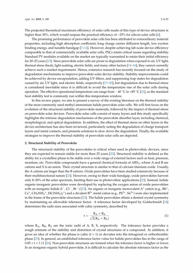
Figure 1a,b shows the ideal case of cubic symmetry for perovskites. The cubic symmetrycorresponds to a Pm3m space group with 12-fold coordination for the A cation, 6-fold coordination forthe B cations, and BX6 octahedra residing in the corners [23]. The deviation from cubic symmetry canbe attributed to several factors including the atomic sizes of the constituents. The A cation does notdirectly affect the electronic properties [30–32]; however, the size of A cations can cause distortion ofthe B-X bonds, which undesirably affects the symmetry. The best electronic properties are obtainedwith cubic symmetry due to high ionic bonding. An octahedral tilting occurs when the tolerance factorexceeds the ideal range, and affects the electronic properties.
Appl. Sci. 2019, 9, x FOR PEER REVIEW 3 of 25
In general, an established tolerance factor value for halide perovskites lies in the range of 0.85 < t < 1.11 [26]. Non-perovskite structures are formed when the tolerance factor is higher or lower. In an inorganic-organic hybrid perovskite, it is difficult to calculate the absolute tolerance factor as the organic cation has a non-spherical geometry [27]. However, it is possible to qualitatively analyze the transition of structure in these materials. For example, formamidinium lead iodide, HC(NH2)2PbI3 (FAPbI3), has a larger A cation than methylammonium lead iodide, CH3NH3PbI3 (MAPbI3) and a larger cation would generally represent a higher tolerance factor [28]. Two phases can be obtained in solution-processed FAPbI3 materials. One is the photoactive α-phase (black phase) and the other is a non-photoactive phase (yellow phase or δ-phase) [29].
Figure 1a,b shows the ideal case of cubic symmetry for perovskites. The cubic symmetry corresponds to a Pm3m space group with 12-fold coordination for the A cation, 6-fold coordination for the B cations, and BX6 octahedra residing in the corners [23]. The deviation from cubic symmetry can be attributed to several factors including the atomic sizes of the constituents. The A cation does not directly affect the electronic properties [30–32]; however, the size of A cations can cause distortion of the B-X bonds, which undesirably affects the symmetry. The best electronic properties are obtained with cubic symmetry due to high ionic bonding. An octahedral tilting occurs when the tolerance factor exceeds the ideal range, and affects the electronic properties.
Figure 1. (a) The unit cell of cubic perovskite, where the blue spheres at lattice corners are A cations, the green sphere at the center is a B cation, and the red spheres at the lattice faces are X anions. (b) Another illustration of BX6 octahedral network, where B cations are surrounded by X anions. (c) A tilted BX6 octahedral structure due to non-ideal size effects and additional factors. Reprinted from [23], with permission from Elsevier.
In recent years, methylammonium lead trihalide (MAPbX3) has received increasing attention as an absorber material for perovskite solar cells. However, the stability of MAPbX3 has been found to strongly vary depending on temperature, changing phase or crystal orientation. The structural data of various methylammonium lead trihalides (MAPbX3; X = I, Cl, Br) [33,34] are summarized in Table 1. As indicated in Table 1, both MAPbBr3 and MAPbCl3 crystallize in the cubic phase at room temperature, while MAPbI3 needs to be heated to a temperature higher than 323 K to allow the transition from a tetragonal to a cubic phase. Interestingly, many studies on MAPbI3 materials report that the tetragonal phase of MAPbI3 can still exist even after heating at temperature of 373 K [4,35–37]. This suggests that the tetragonal phase is surprisingly stable in the thin films, but also emphasizes an ambiguity about the exact phase transition temperature and the nature of the phase transition between tetragonal and cubic phases.
Figure 1. (a) The unit cell of cubic perovskite, where the blue spheres at lattice corners are A cations, thegreen sphere at the center is a B cation, and the red spheres at the lattice faces are X anions. (b) Anotherillustration of BX6 octahedral network, where B cations are surrounded by X anions. (c) A tilted BX6
octahedral structure due to non-ideal size effects and additional factors. Reprinted from [23], withpermission from Elsevier.
In recent years, methylammonium lead trihalide (MAPbX3) has received increasing attentionas an absorber material for perovskite solar cells. However, the stability of MAPbX3 has been foundto strongly vary depending on temperature, changing phase or crystal orientation. The structuraldata of various methylammonium lead trihalides (MAPbX3; X = I, Cl, Br) [33,34] are summarizedin Table 1. As indicated in Table 1, both MAPbBr3 and MAPbCl3 crystallize in the cubic phase atroom temperature, while MAPbI3 needs to be heated to a temperature higher than 323 K to allow thetransition from a tetragonal to a cubic phase. Interestingly, many studies on MAPbI3 materials reportthat the tetragonal phase of MAPbI3 can still exist even after heating at temperature of 373 K [4,35–37].This suggests that the tetragonal phase is surprisingly stable in the thin films, but also emphasizes anambiguity about the exact phase transition temperature and the nature of the phase transition betweentetragonal and cubic phases.
Appl. Sci. 2019, 9, 188 4 of 25
Table 1. Structural data for various methylammonium lead trihalides [22].
Halides (X) Temperature (K) Crystal Structure Space GroupLattice Parameter (Å)
I >327.4 Cubic Pm3m 6.329162.2–327.4 Tetragonal I4/mcm 8.855 12.659
<162.2 Orthorhombic Pna21 8.861 8.581 12.620
3. Impact of Thermal Stress on Perovskites
Typically, device temperatures can be over 45 ◦C higher than ambient temperatures when solarcells operate under direct sunlight. According to International Standards (IEC 61646 climatic chambertests), long-term stability at 85 ◦C is required to compete with other solar cell technologies [38].Therefore, the study of the thermal stability of perovskite solar devices has attracted world-wideresearch attention. Different degradation pathways have been proposed and the topic remainsunder discussion, but the material MAPbI3 (CH3NH3PbI3) clearly loses its excellent light harvestingproperties over time because it evolves into PbI2 after a nominal loss of CH3NH3I. The degradationfrom CH3NH3PbI3 to PbI2 is most likely accompanied by a release of gases via simple sublimation orassisted chemical reaction. It is proposed that the first mass loss step during the thermal degradationof CH3NH3PbI3 and CH3NH3I under an inert atmosphere proceeds as [39]:
CH3NH3PbI3∆→ NH3 + CH3I + PbI2 (2)
CH3NH3I ∆→ NH3 + CH3I (3)
Therefore, the determination of the composition of these released gases during the controlledthermal degradation of CH3NH3PbI3 is expected to pinpoint the degradation pathways. Differentinterpretations can be found in the literature regarding the chemical nature of these released gasesduring thermal degradation and several studies have analyzed the effect of intrinsic degradation andthermal stress on the perovskites. Herein, an overview of the impact of thermal stress on perovskites,based on different aspects such as chemical, crystallographic, morphological and optical degradation,is described.
3.1. Chemical and Structural Degradation
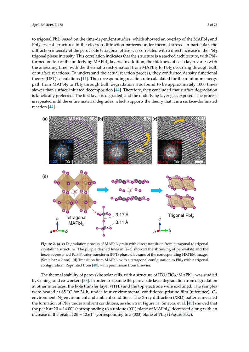
Fan, et al. [40] studied the thermal degradation of MAPbI3 by fabricating MAPbI3 microplates.Microplates are highly crystalline and thus provide an outstanding opportunity to study the structuraldegradation mechanisms of perovskites. The authors investigated the crystal structure under thermalstimulation using in-situ high-resolution transmission electron microscopy (HRTEM). They found thatalmost 75% of the original perovskite tetragonal phase returned to trigonal PbI2 after 100 s of heatingat 85 ◦C. Degradation is initiated by breaking the weak Pb-I-Pb bond along the (001) direction [41],after which the PbI2 relaxes into its energetically favorable trigonal structure (Figure 2). During thisprocess, CH3NH2 and HI sublime into the gas phase. Their studies conducted in dry and inert gaseousenvironments revealed that no MAPbI3 hydrates are generated during the degradation process [42–44].The authors therefore concluded that the phase transition to PbI2 is not initiated by the intrinsichygroscopicity of alkylammonium cations [38,44], but instead is completely due to the thermallyinduced degradation. They suggested that a sequential transition occurs from tetragonal MAPbI3
Appl. Sci. 2019, 9, 188 5 of 25
to trigonal PbI2 based on the time-dependent studies, which showed an overlap of the MAPbI3 andPbI2 crystal structures in the electron diffraction patterns under thermal stress. In particular, thediffraction intensity of the perovskite tetragonal phase was correlated with a direct increase in the PbI2
trigonal phase intensity. This correlation indicates that the structure is a stacked architecture, with PbI2
formed on top of the underlying MAPbI3 layers. In addition, the thickness of each layer varies withthe annealing time, with the thermal transformation from MAPbI3 to PbI2 occurring through bulkor surface reactions. To understand the actual reaction process, they conducted density functionaltheory (DFT) calculations [44]. The corresponding reaction rate calculated for the minimum energypath from MAPbI3 to PbI2 through bulk degradation was found to be approximately 1000 timesslower than surface-initiated decomposition [44]. Therefore, they concluded that surface degradationis kinetically preferred. The first layer is degraded, and the underlying layer gets exposed. The processis repeated until the entire material degrades, which supports the theory that it is a surface-dominatedreaction [44].
Appl. Sci. 2019, 9, x FOR PEER REVIEW 5 of 25
showed an overlap of the MAPbI3 and PbI2 crystal structures in the electron diffraction patterns under thermal stress. In particular, the diffraction intensity of the perovskite tetragonal phase was correlated with a direct increase in the PbI2 trigonal phase intensity. This correlation indicates that the structure is a stacked architecture, with PbI2 formed on top of the underlying MAPbI3 layers. In addition, the thickness of each layer varies with the annealing time, with the thermal transformation from MAPbI3 to PbI2 occurring through bulk or surface reactions. To understand the actual reaction process, they conducted density functional theory (DFT) calculations [44]. The corresponding reaction rate calculated for the minimum energy path from MAPbI3 to PbI2 through bulk degradation was found to be approximately 1000 times slower than surface-initiated decomposition [44]. Therefore, they concluded that surface degradation is kinetically preferred. The first layer is degraded, and the underlying layer gets exposed. The process is repeated until the entire material degrades, which supports the theory that it is a surface-dominated reaction [44].
Figure 2. (a–c) Degradation process of MAPbI3 grain with direct transition from tetragonal to trigonal crystalline structure. The purple dashed lines in (a–c) showed the shrinking of perovskite and the insets represented Fast Fourier transform (FFT) phase diagrams of the corresponding HRTEM images (Scale bar = 2 nm). (d) Transition from MAPbI3 with a tetragonal configuration to PbI2 with a trigonal configuration. Reprinted from [40], with permission from Elsevier.
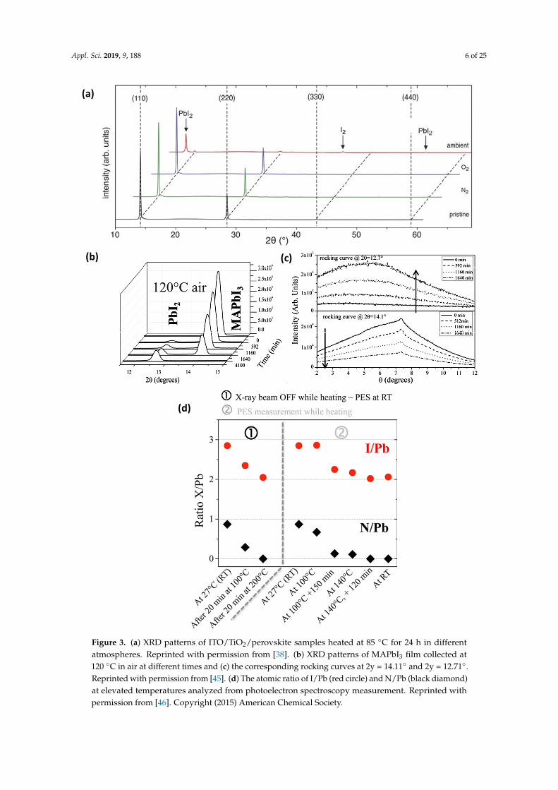
The thermal stability of perovskite solar cells, with a structure of ITO/TiO2/MAPbI3, was studied by Conings and co-workers [38]. In order to separate the perovskite layer degradation from degradation at other interfaces, the hole transfer layer (HTL) and the top electrode were excluded. The samples were heated at 85 °C for 24 h, under four environmental conditions: pristine film (reference), O2 environment, N2 environment and ambient conditions. The X-ray diffraction (XRD) patterns revealed the formation of PbI2 under ambient conditions, as shown in Figure 3a. Smecca, et al. [45] showed that the peak at 2θ = 14.00° (corresponding to a unique (001) plane of MAPbI3) decreased along with an increase of the peak at 2θ = 12.61° (corresponding to a (003) plane of PbI2) (Figure 3b,c).
Figure 2. (a–c) Degradation process of MAPbI3 grain with direct transition from tetragonal to trigonalcrystalline structure. The purple dashed lines in (a–c) showed the shrinking of perovskite and theinsets represented Fast Fourier transform (FFT) phase diagrams of the corresponding HRTEM images(Scale bar = 2 nm). (d) Transition from MAPbI3 with a tetragonal configuration to PbI2 with a trigonalconfiguration. Reprinted from [40], with permission from Elsevier.
The thermal stability of perovskite solar cells, with a structure of ITO/TiO2/MAPbI3, was studiedby Conings and co-workers [38]. In order to separate the perovskite layer degradation from degradationat other interfaces, the hole transfer layer (HTL) and the top electrode were excluded. The sampleswere heated at 85 ◦C for 24 h, under four environmental conditions: pristine film (reference), O2
environment, N2 environment and ambient conditions. The X-ray diffraction (XRD) patterns revealedthe formation of PbI2 under ambient conditions, as shown in Figure 3a. Smecca, et al. [45] showed thatthe peak at 2θ = 14.00◦ (corresponding to a unique (001) plane of MAPbI3) decreased along with anincrease of the peak at 2θ = 12.61◦ (corresponding to a (003) plane of PbI2) (Figure 3b,c).
Appl. Sci. 2019, 9, 188 6 of 25
Appl. Sci. 2019, 9, x FOR PEER REVIEW 6 of 25
Figure 3. (a) XRD patterns of ITO/TiO2/perovskite samples heated at 85 °C for 24 h in different atmospheres. Reprinted with permission from [38]. (b) XRD patterns of MAPbI3 film collected at 120 °C in air at different times and (c) the corresponding rocking curves at 2y = 14.11° and 2y = 12.71°. Reprinted with permission from [45]. (d) The atomic ratio of I/Pb (red circle) and N/Pb (black diamond) at elevated temperatures analyzed from photoelectron spectroscopy measurement. Reprinted with permission from [46]. Copyright (2015) American Chemical Society.
(a)
(d)
(b) (c)
Figure 3. (a) XRD patterns of ITO/TiO2/perovskite samples heated at 85 ◦C for 24 h in differentatmospheres. Reprinted with permission from [38]. (b) XRD patterns of MAPbI3 film collected at120 ◦C in air at different times and (c) the corresponding rocking curves at 2y = 14.11◦ and 2y = 12.71◦.Reprinted with permission from [45]. (d) The atomic ratio of I/Pb (red circle) and N/Pb (black diamond)at elevated temperatures analyzed from photoelectron spectroscopy measurement. Reprinted withpermission from [46]. Copyright (2015) American Chemical Society.
Appl. Sci. 2019, 9, 188 7 of 25
All peaks related to the perovskite layer disappeared in the diffraction pattern during thermalannealing. On the basis of these findings, the authors concluded that the perovskite layer degradedinto PbI2 in less than 10 h. Similarly, Phillippe and co-workers investigated the effect of highertemperatures on both MAPbI3 and MAPbI3−xClx films [46], but used hard X-ray photoelectronspectroscopy (HX-PES) instead of XRD in their study. HX-PES aids the understanding of the filmdecomposition procedure by determining the chemical composition of the sample regardless ofcrystallinity. To investigate the decomposition process, the samples were prepared in an oxygen-and water-free environment and were heated in an analysis chamber under ultra-high vacuum.The films were quantitatively analyzed using HX-PES by extracting the I/Pb and N/Pb atomic ratios.The reduction in these ratios represents the conversion of perovskite to PbI2. The atomic ratio ofI/Pb (red circle) and N/Pb (black diamond) plotted at various temperatures are shown in Figure 3d.Heating at 100 ◦C for 20 min significantly reduced both ratios. Furthermore, upon heating at 200 ◦C,the two ratios decreased to 2 and 0, respectively. This indicates that the film decomposed completelyinto PbI2.
3.2. Morphological Degradation
Several reports have investigated the effect of temperature on the morphology of perovskites. Asmentioned above, Conings and co-workers [38] studied the thermal stability of perovskite solar cellswith an ITO/TiO2/MAPbI3 structure when subjected to heat treatment at 85 ◦C for 24 h under variousenvironmental conditions. High-angle annular dark field (HAADF) TEM was used to understandthe effect of temperature on devices in different environmental conditions. Cross-sectional views ofthe HAADF images are shown in Figure 4a,b. The pristine perovskite device exhibited well-definedlayers stacked evenly on top of each other, while the degraded samples exhibited structural variations.Interestingly, a large PbI2 grain, highlighted in red, is formed in the O2 environment (see Figure 4c).The calculated ratio of Pb/I determined by EDX revealed the highlighted oblong structure to bePbI2. When exposed to ambient atmosphere, more severe device degradation occurred with spot-likestructures in the perovskite and delamination from the TiO2 layer, as shown in Figure 4d. Additionally,topographical AFM images (Figure 4e–h) showed significant structural changes for samples measuredunder ambient conditions. Significant dark areas appearing in AFM images were associated with PbI2
regions, which indicates a photocurrent reduction in those regions upon degradation.Han et al. [17] tested the stability of perovskite solar devices in an environmental chamber,
where the temperature was controlled in the range of −20 ◦C to 100 ◦C. The actual cell temperatureinside the chamber was found to be approximately 30 ◦C higher than the environmental temperature,so the temperatures were denoted as “environmental temperature (actual cell temperature)”, e.g.,55 ◦C (85 ◦C) [17]. The degradation mechanism of CH3NH3PbI3 solar cells was analyzed for 500 hat 55 ◦C (85 ◦C) using cross-sectional focused ion beam–scanning electron microscopy (FIB-SEM).The cross-sectional FIB-SEM images shown in Figure 5 reveal the degradation mechanism of anencapsulated device. The direct exposure equivalent to one sun illumination clearly damaged theentire device, with the most degradation observed in the silver layer. A number of degradation featureswere observed in the degraded cells; including degradation of the silver layer, formation of voidsin spiro-OMeTAD and the perovskite layer, and delamination of the perovskite layer from the TiO2
layer, as shown in Figure 5a–c. Particularly, the formation of a PbI2 layer was found, as indicated by abright contrast in the SEM image (see Figure 5d). It is anticipated that the degradation was initiated bythe reaction of HI gas and Ag in an encapsulated device structure. Therefore, the authors suggestedreplacing the silver contact and using highly heat-resistant encapsulating materials.
Appl. Sci. 2019, 9, 188 8 of 25
Appl. Sci. 2019, 9, x FOR PEER REVIEW 8 of 25
(a)
(b)(f)
(c)
(d)
(e)
(g)
(h)
Figure 4. (a–d) Cross-sectional views of perovskite solar cells heated at 85 °C for 24 h in different atmospheric conditions. The area highlighted in red in the degraded device in O2 environment indicates the presence of PbI2 grain. (e–h) Topographical AFM images of perovskite films that were heated at 85 °C for 24 h in different atmospheric conditions. Reprinted from [38] with permission.
Figure 4. (a–d) Cross-sectional views of perovskite solar cells heated at 85 ◦C for 24 h in differentatmospheric conditions. The area highlighted in red in the degraded device in O2 environment indicatesthe presence of PbI2 grain. (e–h) Topographical AFM images of perovskite films that were heated at85 ◦C for 24 h in different atmospheric conditions. Reprinted from [38] with permission.
Appl. Sci. 2019, 9, 188 9 of 25
Appl. Sci. 2019, 9, x FOR PEER REVIEW 9 of 25
Figure 5. Cross-sectional FIB-SEM images of a (A) (a) A fresh cell and (b-d) cells aged at high temperature (55 °C (85 °C)) and humidity (50%) for 500 h. Degradations in different layers are denoted as voids in the Spiro-OMeTAD layer (□); voids in the perovskite layer (∆); degraded silver layer (○) and formation of particles with higher atomic numbers, likely PbI2 (◊). Reprinted with permission from [17]
3.3. Optical Degradation
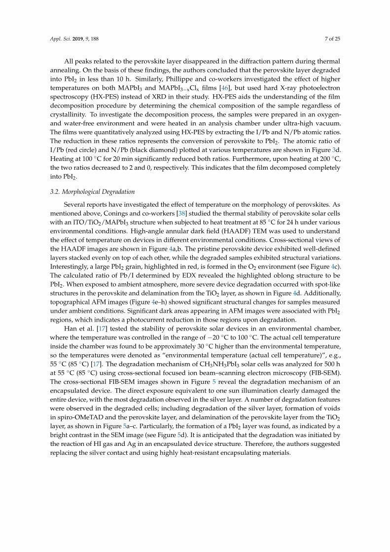
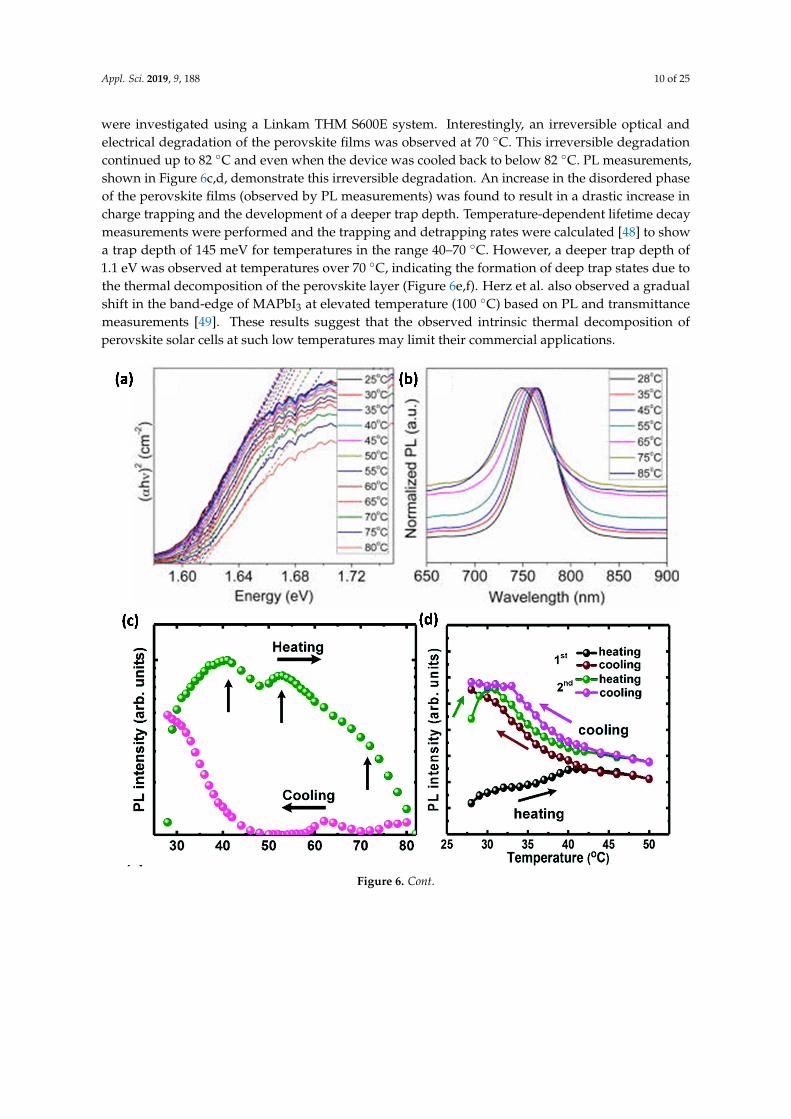
Foley et al. [47] investigated the temperature dependence of the bandgap and energy levels of MAPbI3 by employing absorbance and photoluminescence (PL) spectroscopy (Figure 6a,b). They showed that both valence band maximum (VBM) and conduction band minimum (CBM) levels were reduced by 110 meV and 77 meV, respectively, when the temperature was increased from 25 °C to 85 °C. The bandgap of MAPbI3 also increased by 33 meV, with an increase in temperature. This provided deeper insights into the relationship between the observed shift in VBM level and thermal expansion of the lattice using density functional theory (DFT) calculations. These results are significant when designing MAPbI3 solar cells at different operating temperatures. Recently, the effects of heating and cooling on the performance of MAPbI3−xClx perovskite solar cells were investigated by varying the device temperatures from room temperature to 82 °C and then returning them to room temperature [48]. For this study, temperature-dependent steady-state PL and time-resolved lifetime decay measurements were investigated using a Linkam THM S600E system. Interestingly, an irreversible optical and electrical degradation of the perovskite films was observed at 70 °C. This irreversible
Figure 5. Cross-sectional FIB-SEM images of a (A) (a) A fresh cell and (b-d) cells aged at hightemperature (55 ◦C (85 ◦C)) and humidity (50%) for 500 h. Degradations in different layers aredenoted as voids in the Spiro-OMeTAD layer (�); voids in the perovskite layer (∆); degraded silverlayer (#) and formation of particles with higher atomic numbers, likely PbI2 (♦). Reprinted withpermission from [17].
3.3. Optical Degradation
Foley et al. [47] investigated the temperature dependence of the bandgap and energy levels ofMAPbI3 by employing absorbance and photoluminescence (PL) spectroscopy (Figure 6a,b). Theyshowed that both valence band maximum (VBM) and conduction band minimum (CBM) levels werereduced by 110 meV and 77 meV, respectively, when the temperature was increased from 25 ◦C to 85 ◦C.The bandgap of MAPbI3 also increased by 33 meV, with an increase in temperature. This provideddeeper insights into the relationship between the observed shift in VBM level and thermal expansionof the lattice using density functional theory (DFT) calculations. These results are significant whendesigning MAPbI3 solar cells at different operating temperatures. Recently, the effects of heating andcooling on the performance of MAPbI3−xClx perovskite solar cells were investigated by varying thedevice temperatures from room temperature to 82 ◦C and then returning them to room temperature [48].For this study, temperature-dependent steady-state PL and time-resolved lifetime decay measurements
Appl. Sci. 2019, 9, 188 10 of 25
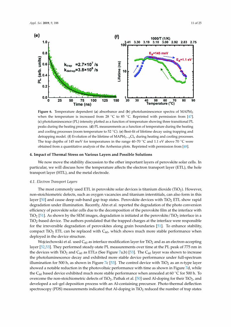
were investigated using a Linkam THM S600E system. Interestingly, an irreversible optical andelectrical degradation of the perovskite films was observed at 70 ◦C. This irreversible degradationcontinued up to 82 ◦C and even when the device was cooled back to below 82 ◦C. PL measurements,shown in Figure 6c,d, demonstrate this irreversible degradation. An increase in the disordered phaseof the perovskite films (observed by PL measurements) was found to result in a drastic increase incharge trapping and the development of a deeper trap depth. Temperature-dependent lifetime decaymeasurements were performed and the trapping and detrapping rates were calculated [48] to showa trap depth of 145 meV for temperatures in the range 40–70 ◦C. However, a deeper trap depth of1.1 eV was observed at temperatures over 70 ◦C, indicating the formation of deep trap states due tothe thermal decomposition of the perovskite layer (Figure 6e,f). Herz et al. also observed a gradualshift in the band-edge of MAPbI3 at elevated temperature (100 ◦C) based on PL and transmittancemeasurements [49]. These results suggest that the observed intrinsic thermal decomposition ofperovskite solar cells at such low temperatures may limit their commercial applications.Appl. Sci. 2019, 9, x FOR PEER REVIEW 11 of 25
Figure 6. Temperature dependent (a) absorbance and (b) photoluminescence spectra of MAPbI3 when the temperature is increased from 28 °C to 85 °C. Reprinted with permission from [47]. (c) photoluminescence (PL) intensity plotted as a function of temperature showing three transitional PL peaks during the heating process. (d) PL measurements as a function of temperature during the heating and cooling processes (room temperature to 52 °C). (e) Best-fit of lifetime decay using trapping and detrapping model. (f) Evolution of the lifetime of MAPbI3−xClx during heating and cooling processes. The trap depths of 145 meV for temperatures in the range 40–70 °C and 1.1 eV above 70 °C were obtained from a quantitative analysis of the Arrhenius plots. Reprinted with permission from [48] .
Figure 6. Cont.
Appl. Sci. 2019, 9, 188 11 of 25
Appl. Sci. 2019, 9, x FOR PEER REVIEW 11 of 25
Figure 6. Temperature dependent (a) absorbance and (b) photoluminescence spectra of MAPbI3 when the temperature is increased from 28 °C to 85 °C. Reprinted with permission from [47]. (c) photoluminescence (PL) intensity plotted as a function of temperature showing three transitional PL peaks during the heating process. (d) PL measurements as a function of temperature during the heating and cooling processes (room temperature to 52 °C). (e) Best-fit of lifetime decay using trapping and detrapping model. (f) Evolution of the lifetime of MAPbI3−xClx during heating and cooling processes. The trap depths of 145 meV for temperatures in the range 40–70 °C and 1.1 eV above 70 °C were obtained from a quantitative analysis of the Arrhenius plots. Reprinted with permission from [48] .
Figure 6. Temperature dependent (a) absorbance and (b) photoluminescence spectra of MAPbI3
when the temperature is increased from 28 ◦C to 85 ◦C. Reprinted with permission from [47].(c) photoluminescence (PL) intensity plotted as a function of temperature showing three transitional PLpeaks during the heating process. (d) PL measurements as a function of temperature during the heatingand cooling processes (room temperature to 52 ◦C). (e) Best-fit of lifetime decay using trapping anddetrapping model. (f) Evolution of the lifetime of MAPbI3−xClx during heating and cooling processes.The trap depths of 145 meV for temperatures in the range 40–70 ◦C and 1.1 eV above 70 ◦C wereobtained from a quantitative analysis of the Arrhenius plots. Reprinted with permission from [48].
4. Impact of Thermal Stress on Various Layers and Possible Solutions
We now move the stability discussion to the other important layers of perovskite solar cells. Inparticular, we will discuss how the temperature affects the electron transport layer (ETL), the holetransport layer (HTL), and the metal electrode.
4.1. Electron Transport Layers
The most commonly used ETL in perovskite solar devices is titanium dioxide (TiO2). However,non-stoichiometric defects, such as oxygen vacancies and titanium interstitials, can also form in thislayer [50] and cause deep sub-band gap trap states. Perovskite devices with TiO2 ETL show rapiddegradation under illumination. Recently, Ahn et al. reported the degradation of the photo conversionefficiency of perovskite solar cells due to the decomposition of the perovskite film at the interface withTiO2 [51]. As shown by the SEM images, degradation is initiated at the perovskite/TiO2 interface in aTiO2-based device. The authors postulated that the trapped charges at the interface were responsiblefor the irreversible degradation of perovskites along grain boundaries [51]. To enhance stability,compact TiO2 ETL can be replaced with C60, which shows much more stable performance whendeployed in the device structure.
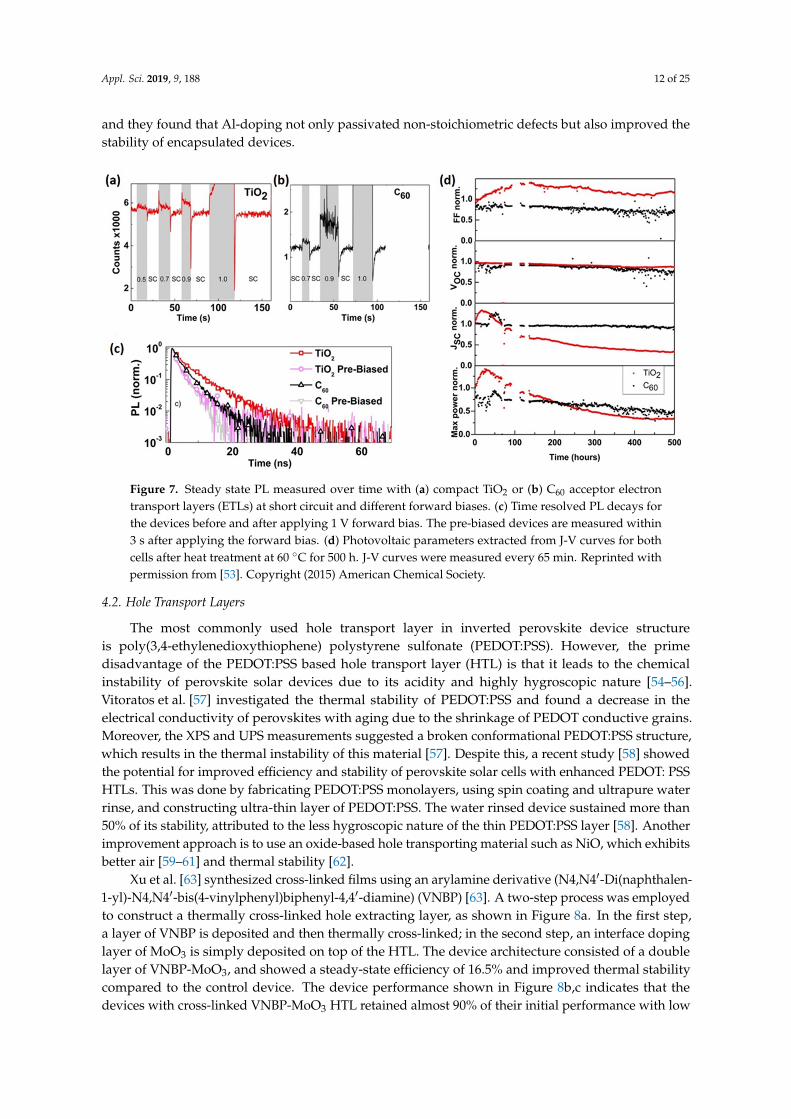
Wojciechowski et al. used C60 as interface modification layer for TiO2 and as an electron-acceptinglayer [52,53]. They performed steady-state PL measurements over time at the PL peak of 775 nm inthe devices with TiO2 and C60 as ETLs (See Figure 7a,b) [53]. The C60 layer was shown to increasethe photoluminescence decay and exhibited more stable device performance under full-spectrumillumination for 500 h, as shown in Figure 7c [53]. The control device with TiO2 as an n-type layershowed a notable reduction in the photovoltaic performance with time as shown in Figure 7d, whilethe C60 based device exhibited much more stable performance when annealed at 60 ◦C for 500 h. Toovercome the non-stoichiometric defects of TiO2, Pathak et al. [50] used Al-doping for their TiO2, anddeveloped a sol–gel deposition process with an Al-containing precursor. Photo-thermal deflectionspectroscopy (PDS) measurements indicated that Al-doping in TiO2 reduced the number of trap states
Appl. Sci. 2019, 9, 188 12 of 25
and they found that Al-doping not only passivated non-stoichiometric defects but also improved thestability of encapsulated devices.
Appl. Sci. 2019, 9, x FOR PEER REVIEW 12 of 25
4. Impact of Thermal Stress on Various Layers and Possible Solutions
We now move the stability discussion to the other important layers of perovskite solar cells. In particular, we will discuss how the temperature affects the electron transport layer (ETL), the hole transport layer (HTL), and the metal electrode.
4.1. Electron Transport Layers
The most commonly used ETL in perovskite solar devices is titanium dioxide (TiO2). However, non-stoichiometric defects, such as oxygen vacancies and titanium interstitials, can also form in this layer [50] and cause deep sub-band gap trap states. Perovskite devices with TiO2 ETL show rapid degradation under illumination. Recently, Ahn et al. reported the degradation of the photo conversion efficiency of perovskite solar cells due to the decomposition of the perovskite film at the interface with TiO2 [51]. As shown by the SEM images, degradation is initiated at the perovskite/TiO2 interface in a TiO2-based device. The authors postulated that the trapped charges at the interface were responsible for the irreversible degradation of perovskites along grain boundaries [51]. To enhance stability, compact TiO2 ETL can be replaced with C60, which shows much more stable performance when deployed in the device structure.
Wojciechowski et al. used C60 as interface modification layer for TiO2 and as an electron-accepting layer [52,53]. They performed steady-state PL measurements over time at the PL peak of 775 nm in the devices with TiO2 and C60 as ETLs (See Figure 7a,b) [53]. The C60 layer was shown to increase the photoluminescence decay and exhibited more stable device performance under full-spectrum illumination for 500 h, as shown in Figure 7c [53]. The control device with TiO2 as an n-type layer showed a notable reduction in the photovoltaic performance with time as shown in Figure 7d, while the C60 based device exhibited much more stable performance when annealed at 60 °C for 500 h. To overcome the non-stoichiometric defects of TiO2, Pathak et al. [50] used Al-doping for their TiO2, and developed a sol–gel deposition process with an Al-containing precursor. Photo-thermal deflection spectroscopy (PDS) measurements indicated that Al-doping in TiO2 reduced the number of trap states and they found that Al-doping not only passivated non-stoichiometric defects but also improved the stability of encapsulated devices.
Figure 7. Steady state PL measured over time with (a) compact TiO2 or (b) C60 acceptor electron transport layers (ETLs) at short circuit and different forward biases. (c) Time resolved PL decays for the devices before and after applying 1 V forward bias. The pre-biased devices are measured within 3 s after applying the forward bias. (d) Photovoltaic parameters extracted from J-V curves for both cells after heat treatment at 60 °C for 500 h. J-V curves were measured every 65 min. Reprinted with permission from [53]. Copyright (2015) American Chemical Society.
Figure 7. Steady state PL measured over time with (a) compact TiO2 or (b) C60 acceptor electrontransport layers (ETLs) at short circuit and different forward biases. (c) Time resolved PL decays forthe devices before and after applying 1 V forward bias. The pre-biased devices are measured within3 s after applying the forward bias. (d) Photovoltaic parameters extracted from J-V curves for bothcells after heat treatment at 60 ◦C for 500 h. J-V curves were measured every 65 min. Reprinted withpermission from [53]. Copyright (2015) American Chemical Society.
4.2. Hole Transport Layers
The most commonly used hole transport layer in inverted perovskite device structureis poly(3,4-ethylenedioxythiophene) polystyrene sulfonate (PEDOT:PSS). However, the primedisadvantage of the PEDOT:PSS based hole transport layer (HTL) is that it leads to the chemicalinstability of perovskite solar devices due to its acidity and highly hygroscopic nature [54–56].Vitoratos et al. [57] investigated the thermal stability of PEDOT:PSS and found a decrease in theelectrical conductivity of perovskites with aging due to the shrinkage of PEDOT conductive grains.Moreover, the XPS and UPS measurements suggested a broken conformational PEDOT:PSS structure,which results in the thermal instability of this material [57]. Despite this, a recent study [58] showedthe potential for improved efficiency and stability of perovskite solar cells with enhanced PEDOT: PSSHTLs. This was done by fabricating PEDOT:PSS monolayers, using spin coating and ultrapure waterrinse, and constructing ultra-thin layer of PEDOT:PSS. The water rinsed device sustained more than50% of its stability, attributed to the less hygroscopic nature of the thin PEDOT:PSS layer [58]. Anotherimprovement approach is to use an oxide-based hole transporting material such as NiO, which exhibitsbetter air [59–61] and thermal stability [62].
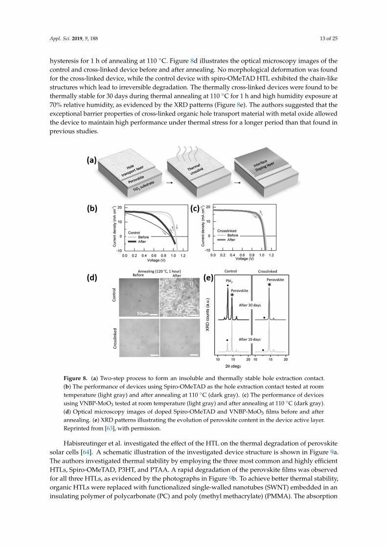
Xu et al. [63] synthesized cross-linked films using an arylamine derivative (N4,N4′-Di(naphthalen-1-yl)-N4,N4′-bis(4-vinylphenyl)biphenyl-4,4′-diamine) (VNBP) [63]. A two-step process was employedto construct a thermally cross-linked hole extracting layer, as shown in Figure 8a. In the first step,a layer of VNBP is deposited and then thermally cross-linked; in the second step, an interface dopinglayer of MoO3 is simply deposited on top of the HTL. The device architecture consisted of a doublelayer of VNBP-MoO3, and showed a steady-state efficiency of 16.5% and improved thermal stabilitycompared to the control device. The device performance shown in Figure 8b,c indicates that thedevices with cross-linked VNBP-MoO3 HTL retained almost 90% of their initial performance with low
Appl. Sci. 2019, 9, 188 13 of 25
hysteresis for 1 h of annealing at 110 ◦C. Figure 8d illustrates the optical microscopy images of thecontrol and cross-linked device before and after annealing. No morphological deformation was foundfor the cross-linked device, while the control device with spiro-OMeTAD HTL exhibited the chain-likestructures which lead to irreversible degradation. The thermally cross-linked devices were found to bethermally stable for 30 days during thermal annealing at 110 ◦C for 1 h and high humidity exposure at70% relative humidity, as evidenced by the XRD patterns (Figure 8e). The authors suggested that theexceptional barrier properties of cross-linked organic hole transport material with metal oxide allowedthe device to maintain high performance under thermal stress for a longer period than that found inprevious studies.
Appl. Sci. 2019, 9, x FOR PEER REVIEW 14 of 25
Figure 8. (a) Two-step process to form an insoluble and thermally stable hole extraction contact. (b) The performance of devices using Spiro-OMeTAD as the hole extraction contact tested at room temperature (light gray) and after annealing at 110 °C (dark gray). (c) The performance of devices using VNBP-MoO3 tested at room temperature (light gray) and after annealing at 110 °C (dark gray). (d) Optical microscopy images of doped Spiro-OMeTAD and VNBP-MoO3 films before and after annealing. (e) XRD patterns illustrating the evolution of perovskite content in the device active layer. Reprinted from [63], with permission.
Figure 8. (a) Two-step process to form an insoluble and thermally stable hole extraction contact.(b) The performance of devices using Spiro-OMeTAD as the hole extraction contact tested at roomtemperature (light gray) and after annealing at 110 ◦C (dark gray). (c) The performance of devicesusing VNBP-MoO3 tested at room temperature (light gray) and after annealing at 110 ◦C (dark gray).(d) Optical microscopy images of doped Spiro-OMeTAD and VNBP-MoO3 films before and afterannealing. (e) XRD patterns illustrating the evolution of perovskite content in the device active layer.Reprinted from [63], with permission.
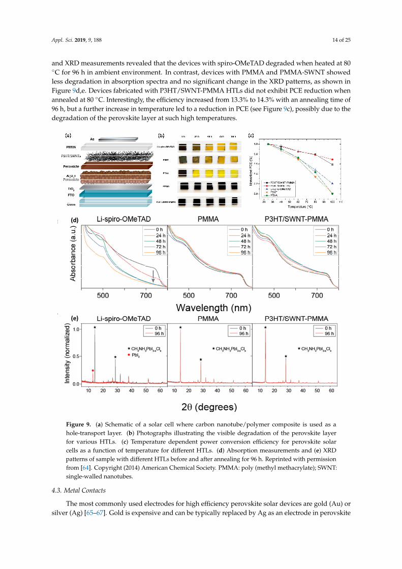
Habisreutinger et al. investigated the effect of the HTL on the thermal degradation of perovskitesolar cells [64]. A schematic illustration of the investigated device structure is shown in Figure 9a.The authors investigated thermal stability by employing the three most common and highly efficientHTLs, Spiro-OMeTAD, P3HT, and PTAA. A rapid degradation of the perovskite films was observedfor all three HTLs, as evidenced by the photographs in Figure 9b. To achieve better thermal stability,organic HTLs were replaced with functionalized single-walled nanotubes (SWNT) embedded in aninsulating polymer of polycarbonate (PC) and poly (methyl methacrylate) (PMMA). The absorption
Appl. Sci. 2019, 9, 188 14 of 25
and XRD measurements revealed that the devices with spiro-OMeTAD degraded when heated at 80◦C for 96 h in ambient environment. In contrast, devices with PMMA and PMMA-SWNT showedless degradation in absorption spectra and no significant change in the XRD patterns, as shown inFigure 9d,e. Devices fabricated with P3HT/SWNT-PMMA HTLs did not exhibit PCE reduction whenannealed at 80 ◦C. Interestingly, the efficiency increased from 13.3% to 14.3% with an annealing time of96 h, but a further increase in temperature led to a reduction in PCE (see Figure 9c), possibly due to thedegradation of the perovskite layer at such high temperatures.Appl. Sci. 2019, 9, x FOR PEER REVIEW 15 of 25
(d)
(e)
Figure 9. (a) Schematic of a solar cell where carbon nanotube/polymer composite is used as a hole-transport layer. (b) Photographs illustrating the visible degradation of the perovskite layer for various HTLs. (c) Temperature dependent power conversion efficiency for perovskite solar cells as a function of temperature for different HTLs. (d) Absorption measurements and (e) XRD patterns of sample with different HTLs before and after annealing for 96 h. Reprinted with permission from [64]. Copyright (2014) American Chemical Society. PMMA: poly (methyl methacrylate); SWNT: single-walled nanotubes.
4.3. Metal Contacts
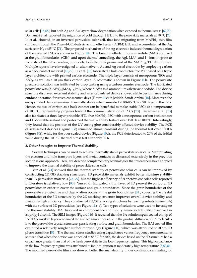
The most commonly used electrodes for high efficiency perovskite solar devices are gold (Au) or silver (Ag) [65–67]. Gold is expensive and can be typically replaced by Ag as an electrode in perovskite solar cells [18,68], but both Ag and Au layers show degradation when exposed to thermal stress [69,70]. Domanski et al. reported the migration of gold through HTL into the perovskite materials at 70 °C [70]. Li et al. showed, in an inverted perovskite solar cell, that ions migrating from MAPbI3 thin film diffused through the Phenyl-C61-butyric acid methyl ester (PCBM) ETL and accumulated at the Ag surface in N2 at 85 °C [71]. The proposed mechanism of the Ag-electrode induced thermal degradation of the inverted PSCs is shown in Figure 10a. The loss of methylammonium iodide (MAI) occurred at the grain boundaries (GBs), and upon thermal annealing, the AgI, MA+, and I− ions migrate to reconstruct the GBs, creating more defects in the bulk grains and at the MAPbI3/PCBM interface. Multiple reports have investigated an alternative to Au and Ag based electrodes by employing carbon as a back-contact material [16,72]. Li et al. [16]
Figure 9. (a) Schematic of a solar cell where carbon nanotube/polymer composite is used as ahole-transport layer. (b) Photographs illustrating the visible degradation of the perovskite layerfor various HTLs. (c) Temperature dependent power conversion efficiency for perovskite solarcells as a function of temperature for different HTLs. (d) Absorption measurements and (e) XRDpatterns of sample with different HTLs before and after annealing for 96 h. Reprinted with permissionfrom [64]. Copyright (2014) American Chemical Society. PMMA: poly (methyl methacrylate); SWNT:single-walled nanotubes.
4.3. Metal Contacts
The most commonly used electrodes for high efficiency perovskite solar devices are gold (Au) orsilver (Ag) [65–67]. Gold is expensive and can be typically replaced by Ag as an electrode in perovskite
Appl. Sci. 2019, 9, 188 15 of 25
solar cells [18,68], but both Ag and Au layers show degradation when exposed to thermal stress [69,70].Domanski et al. reported the migration of gold through HTL into the perovskite materials at 70 ◦C [70].Li et al. showed, in an inverted perovskite solar cell, that ions migrating from MAPbI3 thin filmdiffused through the Phenyl-C61-butyric acid methyl ester (PCBM) ETL and accumulated at the Agsurface in N2 at 85 ◦C [71]. The proposed mechanism of the Ag-electrode induced thermal degradationof the inverted PSCs is shown in Figure 10a. The loss of methylammonium iodide (MAI) occurredat the grain boundaries (GBs), and upon thermal annealing, the AgI, MA+, and I− ions migrate toreconstruct the GBs, creating more defects in the bulk grains and at the MAPbI3/PCBM interface.Multiple reports have investigated an alternative to Au and Ag based electrodes by employing carbonas a back-contact material [16,72]. Li et al. [16] fabricated a hole-conductor-free PSC based on a triplelayer architecture with printed carbon electrode. The triple layer consists of mesoporous TiO2 andZrO2, as well as a 10 µm thick carbon layer. A schematic is shown in Figure 10b. The perovskiteprecursor solution was infiltrated by drop casting using a carbon counter electrode. The fabricatedperovskite was (5-AVA)x(MA)1−xPbI3, where 5-AVA is 5-ammoniumvaleric acid iodide. The devicestructure displayed excellent stability and an encapsulated device showed stable performance duringoutdoor operation for seven consecutive days (Figure 10c) in Jeddah, Saudi Arabia [16]. Moreover, theencapsulated device remained thermally stable when annealed at 80–85 ◦C for 90 days, in the dark.Hence, the use of carbon as a back-contact can be beneficial to make stable PSCs at a temperatureof 100 ◦C, representing progress toward the commercialization of PSCs [73]. Baranwal et al. [73]also fabricated a three-layer printable HTL-free MAPbI3 PSC with a mesoporous carbon back contactand UV-curable sealant and performed thermal stability tests of over 1500 h at 100 ◦C. Interestingly,they found that the position of the UV-curing glue considerably affected device stability. The PCEof side-sealed devices (Figure 10e) remained almost constant during the thermal test over 1500 h(Figure 10f), while for the over-sealed device (Figure 10d), the PCE deteriorated to 20% of the initialvalue during the 100 ◦C thermal stress test after only 30 h.
5. Other Strategies to Improve Thermal Stability
Several techniques can be used to achieve thermally stable perovskite solar cells. Manipulatingthe electron and hole transport layers and metal contacts as discussed extensively in the previoussection is one approach. Here, we describe complementary technologies that researchers have adoptedto improve the thermal stability of perovskite solar cells.
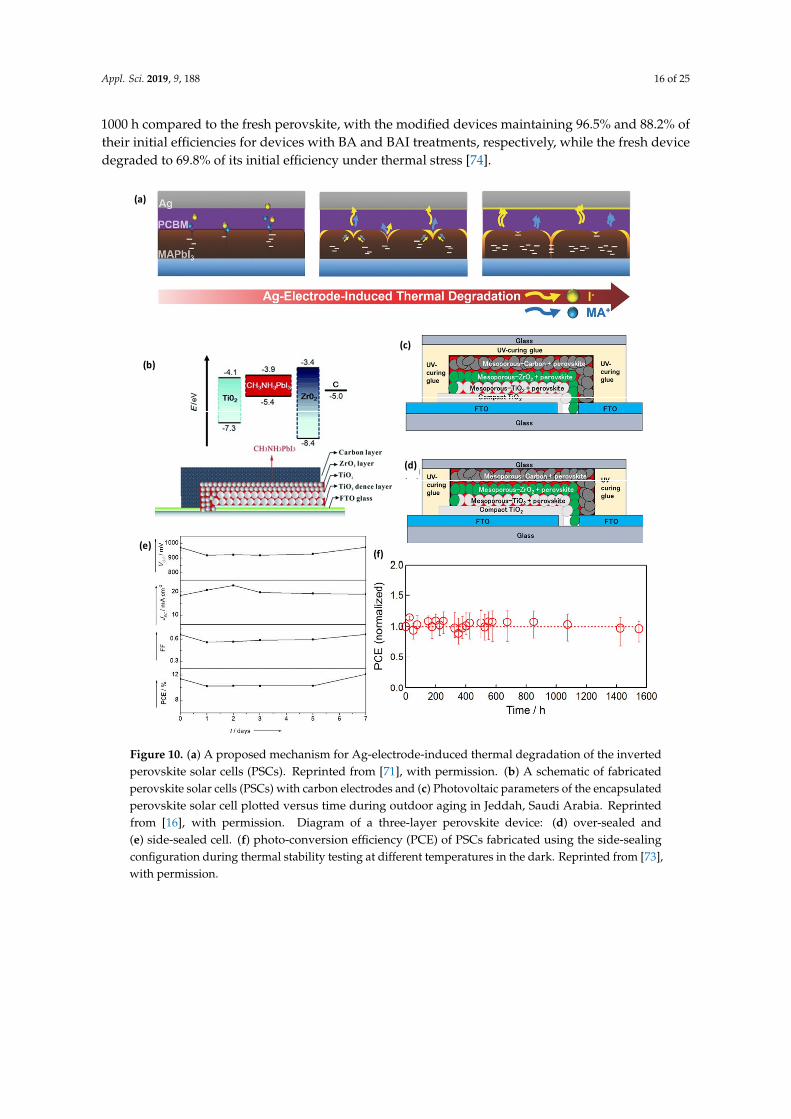
Yun et al. [74] showed that the thermal stability of perovskite solar cells can be improved byconstructing 2D/3D stacking structures. 2D perovskite materials exhibit better moisture stabilitythan 3D perovskite materials [75–79], but the highest efficiency of 2D perovskite solar cells reportedin literature is relatively low [80]. Yun et al. fabricated a thin layer of 2D perovskite on top of 3Dperovskites in order to cover the surface and grain boundaries. Since the grain boundaries of theperovskite are defective and degradation occurs at the grain boundaries [81], covering the crystalboundaries of the 3D structure by the 2D stacking structure improves overall device stability andmaintains high efficiency. They constructed 2D/3D stacking structures by reacting n-butylamine (BA)with the surface of 3D perovskites (see Figure 11a–c). Two types of solutions were used to investigatethe thermal stability: BA dissolved in chlorobenzene and n-butylamine iodide (BAI) dissolved inisopropyl alcohol. The SEM images (Figure 11d–f) revealed that the BA solution spun-coated on top ofthe 3D perovskite layers enhanced the surface smoothness due to the gradual diffusion of BA moleculesinto the perovskite crystal structure, passivating surface and grain boundaries. The BAI treated filmexhibited a relatively rougher surface morphology (Figure 11f), which was attributed to 3D to 2Dphase transition [82]. The thermal stress studies using capacitance versus frequency measurementsshowed that when the device was annealed at 85 ◦C for 20 h, the device based on the 3D structure had acapacitance greater than that of the fresh perovskite in the low-frequency regime. This high capacitancein the low-frequency regime was attributed to ionic migration at moderately high temperature [8,83,84].The modified perovskite film also showed better thermal stability under continuous annealing for
Appl. Sci. 2019, 9, 188 16 of 25
1000 h compared to the fresh perovskite, with the modified devices maintaining 96.5% and 88.2% oftheir initial efficiencies for devices with BA and BAI treatments, respectively, while the fresh devicedegraded to 69.8% of its initial efficiency under thermal stress [74].
Appl. Sci. 2019, 9, x FOR PEER REVIEW 16 of 25
fabricated a hole-conductor-free PSC based on a triple layer architecture with printed carbon electrode. The triple layer consists of mesoporous TiO2 and ZrO2, as well as a 10 µm thick carbon layer. A schematic is shown in Figure 10b. The perovskite precursor solution was infiltrated by drop casting using a carbon counter electrode. The fabricated perovskite was (5-AVA)x(MA)1−xPbI3, where 5-AVA is 5-ammoniumvaleric acid iodide. The device structure displayed excellent stability and an encapsulated device showed stable performance during outdoor operation for seven consecutive days (Figure 10c) in Jeddah, Saudi Arabia [16]. Moreover, the encapsulated device remained thermally stable when annealed at 80–85 °C for 90 days, in the dark. Hence, the use of carbon as a back-contact can be beneficial to make stable PSCs at a temperature of 100 °C, representing progress toward the commercialization of PSCs [73]. Baranwal et al. [73] also fabricated a three-layer printable HTL-free MAPbI3 PSC with a mesoporous carbon back contact and UV-curable sealant and performed thermal stability tests of over 1500 h at 100 °C. Interestingly, they found that the position of the UV-curing glue considerably affected device stability. The PCE of side-sealed devices (Figure 10e) remained almost constant during the thermal test over 1500 h (Figure 10f), while for the over-sealed device (Figure 10d), the PCE deteriorated to 20% of the initial value during the 100 °C thermal stress test after only 30 h.
(a)
(b)
(c)
(d)
(e)(f)
Figure 10. (a) A proposed mechanism for Ag-electrode-induced thermal degradation of the inverted perovskite solar cells (PSCs). Reprinted from [71], with permission. (b) A schematic of fabricated perovskite solar cells (PSCs) with carbon electrodes and (c) Photovoltaic parameters of the encapsulated perovskite solar cell plotted versus time during outdoor aging in Jeddah, Saudi Arabia. Reprinted from [16], with permission. Diagram of a three-layer perovskite device: (d) over-sealed and
Figure 10. (a) A proposed mechanism for Ag-electrode-induced thermal degradation of the invertedperovskite solar cells (PSCs). Reprinted from [71], with permission. (b) A schematic of fabricatedperovskite solar cells (PSCs) with carbon electrodes and (c) Photovoltaic parameters of the encapsulatedperovskite solar cell plotted versus time during outdoor aging in Jeddah, Saudi Arabia. Reprintedfrom [16], with permission. Diagram of a three-layer perovskite device: (d) over-sealed and(e) side-sealed cell. (f) photo-conversion efficiency (PCE) of PSCs fabricated using the side-sealingconfiguration during thermal stability testing at different temperatures in the dark. Reprinted from [73],with permission.
Appl. Sci. 2019, 9, 188 17 of 25
Appl. Sci. 2019, 9, x FOR PEER REVIEW 18 of 25
reduction in PCE of 0.1%/h at 60 °C and 0.21% at 85 °C was also observed. They suggested that this reduction was attributed to the degradation of Spiro-OMeTAD HTL. A different sealing procedure approach can include the use of polymers such as poly(methyl methacrylate) (PMMA), polycarbonate (PC), or polystyrene to protect perovskite films from oxygen and moisture [64]. Along with protection from air, polymers act as an insulating tunneling contact and passivate defects in perovskite film by increasing the efficiency by more than 18% [86]. Habisreutinger et al. proposed a device architecture consisting of single-walled carbon nanotubes (SWNTs) and a polymer matrix of PMMA or PC. The SWNTs in such architecture facilitate selective charge extraction, while the polymer matrix serves as an encapsulating layer to protect the device from moisture penetration [64]. The proposed devices showed enhanced thermal stability at high temperatures of 80 °C in ambient humidity conditions, compared to the control devices.
Figure 11. (a) A schematic of 2D/3D stacking structure obtained from BA-treated perovskite film. (b,c) 2D/3D molecular junctions on the surface and at grain boundaries of 3D perovskite films with BA and BAI treatments, respectively. SEM images of (d) MAPbI3 films, (e) BA-treated MAPbI3 films, and (f) BAI-treated MAPbI3 films. Capacitance−frequency spectra (g) before and (h) after thermal stress at 85 °C for 20 h of the control, BA-treated, and BAI-treated devices; (i) Time evolution of normalized PCE under thermal stress. Reprinted with permission from [74]. Copyright (2018) American Chemical Society.
Another approach to improve thermal stability is substituting the methylammonium (MA) cation of the perovskite material, with mixed cation-based perovskites having been extensively
Figure 11. (a) A schematic of 2D/3D stacking structure obtained from BA-treated perovskite film.(b,c) 2D/3D molecular junctions on the surface and at grain boundaries of 3D perovskite films withBA and BAI treatments, respectively. SEM images of (d) MAPbI3 films, (e) BA-treated MAPbI3
films, and (f) BAI-treated MAPbI3 films. Capacitance−frequency spectra (g) before and (h) afterthermal stress at 85 ◦C for 20 h of the control, BA-treated, and BAI-treated devices; (i) Time evolutionof normalized PCE under thermal stress. Reprinted with permission from [74]. Copyright (2018)American Chemical Society.
Li et al. investigated the thermal stability of MAPbI3 by modifying its surface. In that study,an additive butylphosphonic acid 4-ammoniumchloride (4-ABPACl) was spun-coated onto thesurface [16]. Structural, morphological, and elemental examinations then showed that the additiveacted as a crosslink between perovskite grains. The phosphonic acid ammonium additive facilitatedobtaining a smooth surface layer because perovskite was incorporated into the mesoporous TiO2
scaffold. The 4-ABPACl additive increased the absorption and almost doubled the efficiency ofthe devices, compared to the control device. The effect of thermal stress was investigated on anencapsulated device at 45 ◦C under 10 mW/cm2 illumination. The CH3NH3PbI3-ABPA modifieddevices maintained 90% of their initial efficiency after one week. A heat stress test was performedon CH3NH3PbI3-ABPA device at 85 ◦C in the dark for 350 h to confirm if the modified device couldendure the exposure to high temperature and the modified device maintained 80% of its initial PCEafter 350 h of continuous annealing.
Appl. Sci. 2019, 9, 188 18 of 25
Perovskite thin films are very sensitive to oxygen and moisture, even though different cations andmixed halides have been employed in perovskite structures. Moisture ingress is known to acceleratethe thermal degradation of perovskite solar cells, so encapsulation is used to protect perovskites frommoisture. Matteocci et al. [85] compared five different glass-glass sealing procedures and found anoptimized procedure using Kapton and glue bonded glass. They also showed that an additional edgesealing increased moisture resistance, leading to improved thermal stability with the ability to maintaininitial PCE for over 1300 h of shelf-life. Furthermore, they found that the optimized sealing procedureprevents the intrinsic degradation of CH3NH3PbI3, although a reduction in PCE of 0.1%/h at 60 ◦C and0.21% at 85 ◦C was also observed. They suggested that this reduction was attributed to the degradationof Spiro-OMeTAD HTL. A different sealing procedure approach can include the use of polymerssuch as poly(methyl methacrylate) (PMMA), polycarbonate (PC), or polystyrene to protect perovskitefilms from oxygen and moisture [64]. Along with protection from air, polymers act as an insulatingtunneling contact and passivate defects in perovskite film by increasing the efficiency by more than18% [86]. Habisreutinger et al. proposed a device architecture consisting of single-walled carbonnanotubes (SWNTs) and a polymer matrix of PMMA or PC. The SWNTs in such architecture facilitateselective charge extraction, while the polymer matrix serves as an encapsulating layer to protect thedevice from moisture penetration [64]. The proposed devices showed enhanced thermal stability athigh temperatures of 80 ◦C in ambient humidity conditions, compared to the control devices.
Another approach to improve thermal stability is substituting the methylammonium (MA) cationof the perovskite material, with mixed cation-based perovskites having been extensively studied byresearchers. Enhanced crystallinity and structural stability with improved power conversion efficiencywere obtained by replacing MA with formamidinium (FA) [87–89], cesium (Cs) cations, [90–93] or amixture of the two [94–98]. Eperon et al. reported a relatively slower degradation for FAPbI3 comparedto MAPbI3 when annealed at 150 ◦C [89]. Although FAPbI3 is more thermally stable than MAPbI3, thestructural instability of FAPbI3 in the presence of moisture limits its use in perovskite solar devices [99].Replacing FAI by MAI or MABr results in FA1−xMAxPbI3 or FA1−xMAxPbI3−yBry perovskites, with astabilized black perovskite phase [87,88]. Binek et al. achieved 3D black FA-based perovskite by addinga smaller MA cation compared to FA, resulting in no phase transition in the 25–150 ◦C temperaturerange [98]. Such stability improvement was ascribed to the larger dipole moment of MA, whichincreases the Coulomb interactions within the structure [98].
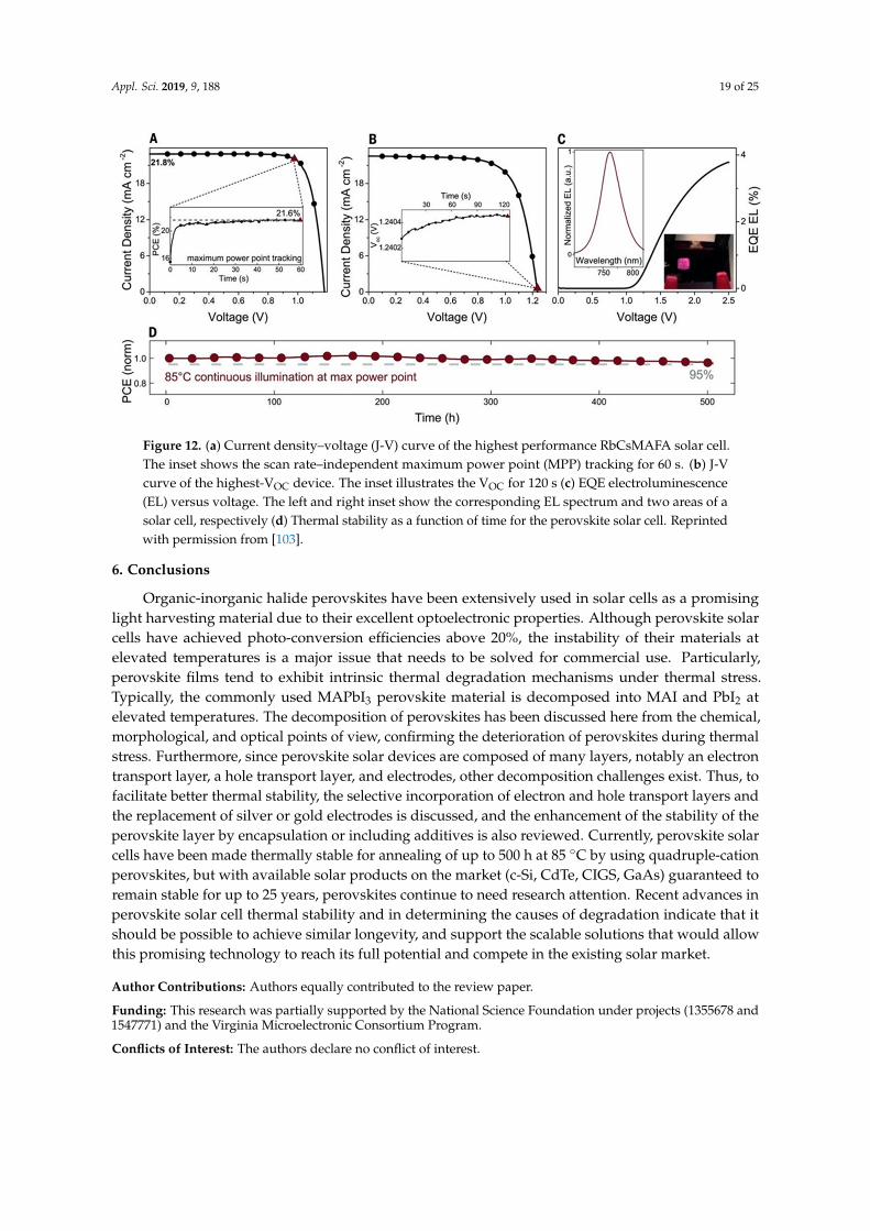
However, since the unstable nature of the MA cation can hinder long-term stability, inorganiccations, such as cesium, have attracted on-going research attention due to their establishedsustainability at higher temperatures [90–93]. For example, CsPbI3 based perovskite forms in acubic structure with a band gap of 1.73 eV [89,90]. but crystallizes into a photo-inactive yellow phasewhen exposed to air. In contrast, CsPbBr3 is less sensitive to moisture [92,100], but does not havea favorable bandgap for single-junction solar cell applications [101]. Since inorganic cesium leadhalide perovskites (CsPbX3, X = Cl, Br, I) have demonstrated advantageous thermal stability, effortshave been made to develop mixed cation perovskites with simultaneous high efficiency and goodthermal stability [28,94–96,102]. Several groups have studied Cs/FA mixtures, showing enhancedstability results in light, moisture, and heat compared to the pure material (FAPbI3). Saliba et al. havealso fabricated solar cells using quadruple-cation perovskites (MA/FA/Cs/Rb), revealing improvedreproducibility and stability [103]. Saliba et al. tested devices annealed for 500 h at 85 ◦C undercontinuous illumination in a nitrogen atmosphere, and the current-voltage characteristics of the bestperformance solar cells and the external quantum efficiency (EQE) electroluminescence (EL) are shownin Figure 12a–c, where the compounded stress test exceeds industrial standards [104]. They showedthat the device retained 95% of its initial performance when annealed at 85 ◦C for 500 h, as shown inFigure 12d.
Appl. Sci. 2019, 9, 188 19 of 25
Appl. Sci. 2019, 9, x FOR PEER REVIEW 19 of 25
studied by researchers. Enhanced crystallinity and structural stability with improved power conversion efficiency were obtained by replacing MA with formamidinium (FA) [87–89], cesium (Cs) cations, [90–93] or a mixture of the two [94–98]. Eperon et al. reported a relatively slower degradation for FAPbI3 compared to MAPbI3 when annealed at 150 °C [89]. Although FAPbI3 is more thermally stable than MAPbI3, the structural instability of FAPbI3 in the presence of moisture limits its use in perovskite solar devices [99]. Replacing FAI by MAI or MABr results in FA1−xMAxPbI3 or FA1−xMAxPbI3−yBry perovskites, with a stabilized black perovskite phase [87,88]. Binek et al. achieved 3D black FA-based perovskite by adding a smaller MA cation compared to FA, resulting in no phase transition in the 25–150 °C temperature range [98]. Such stability improvement was ascribed to the larger dipole moment of MA, which increases the Coulomb interactions within the structure [98].
However, since the unstable nature of the MA cation can hinder long-term stability, inorganic cations, such as cesium, have attracted on-going research attention due to their established sustainability at higher temperatures [90–93]. For example, CsPbI3 based perovskite forms in a cubic structure with a band gap of 1.73 eV [89,90]. but crystallizes into a photo-inactive yellow phase when exposed to air. In contrast, CsPbBr3 is less sensitive to moisture [92,100], but does not have a favorable bandgap for single-junction solar cell applications [101]. Since inorganic cesium lead halide perovskites (CsPbX3, X = Cl, Br, I) have demonstrated advantageous thermal stability, efforts have been made to develop mixed cation perovskites with simultaneous high efficiency and good thermal stability [28,94–96,102]. Several groups have studied Cs/FA mixtures, showing enhanced stability results in light, moisture, and heat compared to the pure material (FAPbI3). Saliba et al. have also fabricated solar cells using quadruple-cation perovskites (MA/FA/Cs/Rb), revealing improved reproducibility and stability [103]. Saliba et al. tested devices annealed for 500 h at 85 °C under continuous illumination in a nitrogen atmosphere, and the current-voltage characteristics of the best performance solar cells and the external quantum efficiency (EQE) electroluminescence (EL) are shown in Figure 12a–c, where the compounded stress test exceeds industrial standards [104]. They showed that the device retained 95% of its initial performance when annealed at 85 °C for 500 h, as shown in Figure 12d.
Figure 12. (a) Current density–voltage (J-V) curve of the highest performance RbCsMAFA solar cell. The inset shows the scan rate–independent maximum power point (MPP) tracking for 60 s. (b) J-V curve of the highest-VOC device. The inset illustrates the VOC for 120 s (c) EQE electroluminescence (EL) versus voltage. The left and right inset show the corresponding EL spectrum and two areas of a solar cell, respectively (d) Thermal stability as a function of time for the perovskite solar cell. Reprinted with permission from [103].
6. Conclusions
Figure 12. (a) Current density–voltage (J-V) curve of the highest performance RbCsMAFA solar cell.The inset shows the scan rate–independent maximum power point (MPP) tracking for 60 s. (b) J-Vcurve of the highest-VOC device. The inset illustrates the VOC for 120 s (c) EQE electroluminescence(EL) versus voltage. The left and right inset show the corresponding EL spectrum and two areas of asolar cell, respectively (d) Thermal stability as a function of time for the perovskite solar cell. Reprintedwith permission from [103].
6. Conclusions
Organic-inorganic halide perovskites have been extensively used in solar cells as a promisinglight harvesting material due to their excellent optoelectronic properties. Although perovskite solarcells have achieved photo-conversion efficiencies above 20%, the instability of their materials atelevated temperatures is a major issue that needs to be solved for commercial use. Particularly,perovskite films tend to exhibit intrinsic thermal degradation mechanisms under thermal stress.Typically, the commonly used MAPbI3 perovskite material is decomposed into MAI and PbI2 atelevated temperatures. The decomposition of perovskites has been discussed here from the chemical,morphological, and optical points of view, confirming the deterioration of perovskites during thermalstress. Furthermore, since perovskite solar devices are composed of many layers, notably an electrontransport layer, a hole transport layer, and electrodes, other decomposition challenges exist. Thus, tofacilitate better thermal stability, the selective incorporation of electron and hole transport layers andthe replacement of silver or gold electrodes is discussed, and the enhancement of the stability of theperovskite layer by encapsulation or including additives is also reviewed. Currently, perovskite solarcells have been made thermally stable for annealing of up to 500 h at 85 ◦C by using quadruple-cationperovskites, but with available solar products on the market (c-Si, CdTe, CIGS, GaAs) guaranteed toremain stable for up to 25 years, perovskites continue to need research attention. Recent advances inperovskite solar cell thermal stability and in determining the causes of degradation indicate that itshould be possible to achieve similar longevity, and support the scalable solutions that would allowthis promising technology to reach its full potential and compete in the existing solar market.
Author Contributions: Authors equally contributed to the review paper.
Funding: This research was partially supported by the National Science Foundation under projects (1355678 and1547771) and the Virginia Microelectronic Consortium Program.
Conflicts of Interest: The authors declare no conflict of interest.
Appl. Sci. 2019, 9, 188 20 of 25
References
1. Wright, M.; Uddin, A. Organic—Inorganic hybrid solar cells: A comparative review. Sol. Energy Mater Sol.Cells 2012, 107, 87–111. [CrossRef]
2. NREL Solar Cell Efficiency Chart. Available online: http://www.nrel.gov/ncpv/ (accessed on9 September 2018).
3. Kojima, A.; Teshima, K.; Shirai, Y.; Miyasaka, T. Organometal halide perovskites as visible-light sensitizersfor photovoltaic cells. J. Am. Chem. Soc. 2009, 131, 6050–6051. [CrossRef] [PubMed]
12. Noh, J.H.; Im, S.H.; Heo, J.H.; Mandal, T.N.; Seok, S.I. Chemical management for colorful, efficient, and stableinorganic–organic hybrid nanostructured solar cells. Nano Lett. 2013, 13, 1764–1769. [CrossRef] [PubMed]
13. Wang, D.; Wright, M.; Elumalai, N.K.; Uddin, A. Stability of perovskite solar cells. Sol. Energy Mater Sol. Cells2016, 147, 255–275. [CrossRef]
14. Niu, G.; Guo, X.; Wang, L. Review of recent progress in chemical stability of perovskite solar cells. J. Mater.Chem. A 2015, 3, 8970–8980. [CrossRef]
15. Grätzel, M. The light and shade of perovskite solar cells. Nat. Mater. 2014, 13, 838. [CrossRef] [PubMed]16. Li, X.; Tschumi, M.; Han, H.; Babkair, S.S.; Alzubaydi, R.A.; Ansari, A.A.; Habib, S.S.; Nazeeruddin, M.K.;
Zakeeruddin, S.M.; Grätzel, M. Outdoor performance and stability under elevated temperatures andlong-term light soaking of triple-layer mesoporous perovskite photovoltaics. Energy Technol. 2015, 3,551–555. [CrossRef]
17. Han, Y.; Meyer, S.; Dkhissi, Y.; Weber, K.; Pringle, J.M.; Bach, U.; Spiccia, L.; Cheng, Y.B. Degradationobservations of encapsulated planar CH3NH3PbI3 perovskite solar cells at high temperatures and humidity.J. Mater. Chem. A 2015, 3, 8139–8147. [CrossRef]
19. Chen, W.; Wu, Y.; Yue, Y.; Liu, J.; Zhang, W.; Yang, X.; Chen, H.; Bi, E.; Ashraful, I.; Grätzel, M.; et al. Efficientand stable large-area perovskite solar cells with inorganic charge extraction layers. Science 2015, aad1015.[CrossRef]
20. Shao, Y.; Yuan, Y.; Huang, J. Correlation of energy disorder and open-circuit voltage in hybrid perovskitesolar cells. Nat. Energy 2016, 1, 15001. [CrossRef]
21. Cheacharoen, R.; Boyd, C.C.; Burkhard, G.F.; Leijtens, T.; Raiford, J.A.; Bush, K.A.; Bent, S.F.; McGehee, M.D.Encapsulating perovskite solar cells to withstand damp heat and thermal cycling. Sustain. Energy Fuels 2018,2, 2398–2406. [CrossRef]
25. Leijtens, T.; Bush, K.; Cheacharoen, R.; Beal, R.; Bowring, A.; McGehee, M.D. Towards enabling stable leadhalide perovskite solar cells; interplay between structural, environmental, and thermal stability. J. Mater.Chem. A 2017, 5, 11483–11500. [CrossRef]
26. Li, C.; Lu, X.; Ding, W.; Feng, L.; Gao, Y.; Guo, Z. Formability of ABX3(X=F, Cl, Br, I) Halide Perovskites.Acta Crystallogr. B 2008, 64, 702–707. [CrossRef] [PubMed]
27. Bakulin, A.A.; Selig, O.; Bakker, H.J.; Rezus, Y.L.; Muller, C.; Glaser, T.; Lovrincic, R.; Sun, Z.; Chen, Z.;Walsh, A.; et al. Real-Time Observation of Organic Cation Reorientation in Methylammonium Lead IodidePerovskites. J. Phys. Chem. Lett. 2015, 6, 3663–3669. [CrossRef] [PubMed]
28. Li, Z.; Yang, M.; Park, J.S.; Wei, S.H.; Berry, J.J.; Zhu, K. Stabilizing perovskite structures by tuning tolerancefactor: Formation of formamidinium and cesium lead iodide solid-state alloys. Chem. Mater. 2015, 28,284–292. [CrossRef]
29. Lee, J.; Seol, D.; Cho, A.; Park, N. High-Efficiency Perovskite Solar Cells Based on the Black Polymorph ofHC(NH2)2PbI3. Adv. Mater. 2014, 26, 4991–4998. [CrossRef]
30. Chang, Y.H.; Park, C.H.; Matsuishi, K. First-Principles Study of the Structural and the Electronic Propertiesof the Lead-Halide-Based Inorganic-Organic Perovskites (CH3NH3)PbX3 and CsPbX3(X=Cl, Br, I). J. KoreanPhys. Soc. 2004, 44, 889–893.
31. Umari, P.; Mosconi, E.; De Angelis, F. Relativistic GW calculations on CH3NH3PbI3 and CH3NH3SnI3
perovskites for solar cell applications. Sci. Rep. 2014, 4, 4467. [CrossRef]32. Umebayashi, T.; Asai, K.; Kondo, T.; Nakao, A. Electronic structures of lead iodide based low-dimensional
crystals. Phys. Rev. B 2003, 67, 155405. [CrossRef]33. Wasylishen, R.E.; Knop, O.; Macdonald, J.B. Cation rotation in methylammonium lead halides. Solid State
Commun. 1985, 56, 581–582. [CrossRef]34. Egger, D.A.; Kronik, L.; Rappe, A.M. Theory of hydrogen migration in organic–inorganic halide perovskites.
perovskite solar cells. Energy Environ. Sci. 2013, 6, 1739–1743. [CrossRef]36. Stoumpos, C.C.; Malliakas, C.D.; Kanatzidis, M.G. Semiconducting tin and lead iodide perovskites
with organic cations: Phase transitions, high mobilities, and near-infrared photoluminescent properties.Inorg. Chem. 2013, 52, 9019–9038. [CrossRef]
41. Pauling, L. The dependence of bond energy on bond length. J. Phys. Chem. 1954, 58, 662–666. [CrossRef]42. Frost, J.M.; Butler, K.T.; Brivio, F.; Hendon, C.H.; Van Schilfgaarde, M.; Walsh, A. Atomistic origins of
high-performance in hybrid halide perovskite solar cells. Nano Lett. 2014, 14, 2584–2590. [CrossRef][PubMed]
43. Christians, J.A.; Miranda Herrera, P.A.; Kamat, P.V. Transformation of the excited state and photovoltaicefficiency of CH3NH3PbI3 perovskite upon controlled exposure to humidified air. J. Am. Chem. Soc. 2015,137, 1530–1538. [CrossRef] [PubMed]
44. Yang, J.; Siempelkamp, B.D.; Liu, D.; Kelly, T.L. Investigation of CH3NH3PbI3 degradation rates andmechanisms in controlled humidity environments using in situ techniques. ACS Nano 2015, 9, 1955–1963.[CrossRef] [PubMed]
53. Wojciechowski, K.; Leijtens, T.; Siprova, S.; Schlueter, C.; Hörantner, M.T.; Wang, J.T.W.; Li, C.Z.; Jen, A.K.Y.;Lee, T.L.; Snaith, H.J. C60 as an efficient n-type compact layer in perovskite solar cells. J. Phys. Chem. Lett.2015, 6, 2399–2405. [CrossRef] [PubMed]
54. Ye, S.; Sun, W.; Li, Y.; Yan, W.; Peng, H.; Bian, Z.; Liu, Z.; Huang, C. CuSCN-Based Inverted Planar PerovskiteSolar Cell with an Average PCE of 15.6%. Nano Lett. 2015, 15, 3723–3728. [CrossRef] [PubMed]
55. Labban, A.E.; Chen, H.; Kirkus, M.; Barbe, J.; Del Gobbo, S.; Neophytou, M.; McCulloch, I. ImprovedEfficiency in Inverted Perovskite Solar Cells Employing a Novel Diarylamino-Substituted Molecule asPEDOT:PSS Replacement. Adv. Energy Mater. 2016, 1502101. [CrossRef]
56. Lee, W.; Song, M.; Park, S.; Nam, S.; Seo, J.; Kim, H.; Kim, Y. Acidity-Controlled Conducting Polymer Filmsfor Organic Thermoelectric Devices with Horizontal and Vertical Architectures. Sci. Rep. 2016, 6, 33795.[CrossRef]
58. Hu, L.; Li, M.; Yang, K.; Xiong, Z.; Yang, B.; Wang, M.; Tang, X.; Zang, Z.; Liu, X.; Li, B.; et al. PEDOT: PSSmonolayers to enhance the hole extraction and stability of perovskite solar cells. J. Mater. Chem. A 2018, 6,16583–16589. [CrossRef]
59. You, J.; Meng, L.; Song, T.-B.; Guo, T.-F.; Yang, Y.; Chang, W.-H.; Hong, Z.; Chen, H.; Zhou, H.; Chen, Q.; et al.Improved Air Stability of Perovskite Solar Cells via Solution- Processed Metal Oxide Transport Layers. Nat.Nanotechnol. 2015, 11, 75–81. [CrossRef]
60. Zhang, H.; Cheng, J.; Lin, F.; He, H.; Mao, J.; Wong, K.S.; Jen, A.K.-Y.; Choy, W.C.H. Pinhole-Free andSurface-Nanostructured NiOx Film by Room-Temperature Solution Process for High- Performance FlexiblePerovskite Solar Cells with Good Stability and Reproducibility. ACS Nano 2016, 10, 1503–1511. [CrossRef]
61. Kim, H.-S.; Seo, J.-Y.; Park, N.-G. Impact of Selective Contacts on Long-Term Stability of CH3NH3PbI3
Perovskite Solar Cells. J. Phys. Chem. C 2016, 120, 27840–27848. [CrossRef]62. Zhao, X.; Kim, H.S.; Seo, J.Y.; Park, N.G. Effect of selective contacts on the thermal stability of perovskite
66. Sheikh, A.D.; Bera, A.; Haque, M.A.; Rakhi, R.B.; Del Gobbo, S.; Alshareef, H.N.; Wu, T. Atmospheric effectson the photovoltaic performance of hybrid perovskite solar cells. Sol. Energy Mater Sol. Cells 2015, 137, 6–14.[CrossRef]
67. Sfyri, G.; Kumar, C.V.; Raptis, D.; Dracopoulos, V.; Lianos, P. Study of perovskite solar cells synthesizedunder ambient conditions and of the performance of small cell modules. Sol. Energy Mater Sol. Cells 2015,134, 60–63. [CrossRef]
69. Divitini, G.; Cacovich, S.; Matteocci, F.; Cina, L.; Di Carlo, A.; Ducati, C. In situ observation of heat-induceddegradation of perovskite solar cells. Nat. Energy. 2016, 1, 15012. [CrossRef]
70. Domanski, K.; Correa-Baena, J.P.; Mine, N.; Nazeeruddin, M.K.; Abate, A.; Saliba, M.; Tress, W.; Hagfeldt, A.;Grätzel, M. Not all that glitters is gold: Metal-migration-induced degradation in perovskite solar cells. ACSnano 2016, 10, 6306–6314. [CrossRef]
71. Li, J.; Dong, Q.; Li, N.; Wang, L. Direct Evidence of Ion Diffusion for the Silver-Electrode-Induced ThermalDegradation of Inverted Perovskite Solar Cells. Adv. Energy Mater. 2017, 7, 1602922. [CrossRef]
72. Mei, A.; Li, X.; Liu, L.; Ku, Z.; Liu, T.; Rong, Y.; Xu, M.; Hu, M.; Chen, J.; Yang, Y.; et al. A hole-conductor–free,fully printable mesoscopic perovskite solar cell with high stability. Science 2014, 345, 295–298. [CrossRef][PubMed]
73. Baranwal, A.K.; Kanaya, S.; Peiris, T.N.; Mizuta, G.; Nishina, T.; Kanda, H.; Miyasaka, T.; Segawa, H.;Ito, S. 100 ◦C thermal stability of printable perovskite solar cells using porous carbon counter electrodes.ChemSusChem 2016, 9, 2604–2608. [CrossRef] [PubMed]
74. Lin, Y.; Bai, Y.; Fang, Y.; Chen, Z.; Yang, S.; Zheng, X.; Tang, S.; Liu, Y.; Zhao, J.; Huang, J. Enhanced thermalstability in perovskite solar cells by assembling 2D/3D stacking structures. J Phys Chem Lett. 2018, 9, 654–658.[CrossRef] [PubMed]
83. Hoque, M.N.F.; Yang, M.; Li, Z.; Islam, N.; Pan, X.; Zhu, K.; Fan, Z. Polarization and Dielectric Study ofMethylammonium Lead Iodide Thin Film to Reveal its Nonferroelectric Nature under Solar Cell OperatingConditions. ACS Energy Lett. 2016, 1, 142–149. [CrossRef]
84. Jonscher, A. Analysis of the Alternating Current Properties of Ionic Conductors. J. Mater. Sci. 1978, 13,553–562. [CrossRef]
85. Matteocci, F.; Cinà, L.; Lamanna, E.; Cacovich, S.; Divitini, G.; Midgley, P.A.; Ducati, C.; Di Carlo, A.Encapsulation for long-term stability enhancement of perovskite solar cells. Nano Energy 2016, 30, 162–172.[CrossRef]
86. Wang, F.; Shimazaki, A.; Yang, F.; Kanahashi, K.; Matsuki, K.; Miyauchi, Y.; Takenobu, T.; Wakamiya, A.;Murata, Y.; Matsuda, K. Highly efficient and stable perovskite solar cells by interfacial engineering usingsolution-processed polymer layer. J. Phys. Chem. C 2017, 121, 1562–1568. [CrossRef]
87. Jeon, N.J.; Noh, J.H.; Yang, W.S.; Kim, Y.C.; Ryu, S.; Seo, J.; Seok, S.I. Compositional engineering of perovskitematerials for high-performance solar cells. Nature 2015, 517, 476. [CrossRef]
89. Eperon, G.E.; Stranks, S.D.; Menelaou, C.; Johnston, M.B.; Herz, L.M.; Snaith, H.J. Formamidinium leadtrihalide: A broadly tunable perovskite for efficient planar heterojunction solar cells. Energy Environ. Sci.2014, 7, 982–988. [CrossRef]
90. Eperon, G.E.; Paterno, G.M.; Sutton, R.J.; Zampetti, A.; Haghighirad, A.A.; Cacialli, F.; Snaith, H.J. Inorganiccesium lead iodide perovskite solar cells. J. Mater. Chem. A 2015, 3, 19688–19695. [CrossRef]
91. Sutton, R.J.; Eperon, G.E.; Miranda, L.; Parrott, E.S.; Kamino, B.A.; Patel, J.B.; Hörantner, M.T.; Johnston, M.B.;Haghighirad, A.A.; Moore, D.T.; et al. Bandgap-tunable cesium lead halide perovskites with high thermalstability for efficient solar cells. Adv. Energy Mater. 2016, 6, 1502458. [CrossRef]
92. Kulbak, M.; Gupta, S.; Kedem, N.; Levine, I.; Bendikov, T.; Hodes, G.; Cahen, D. Cesium enhances long-termstability of lead bromide perovskite-based solar cells. J. Phys. Chem. Lett. 2015, 7, 167–172. [CrossRef][PubMed]
93. Beal, R.E.; Slotcavage, D.J.; Leijtens, T.; Bowring, A.R.; Belisle, R.A.; Nguyen, W.H.; Burkhard, G.F.; Hoke, E.T.;McGehee, M.D. Cesium lead halide perovskites with improved stability for tandem solar cells. J. Phys.Chem. Lett. 2016, 7, 746–751. [CrossRef]
94. Saliba, M.; Matsui, T.; Seo, J.Y.; Domanski, K.; Correa-Baena, J.P.; Nazeeruddin, M.K.; Zakeeruddin, S.M.;Tress, W.; Abate, A.; Hagfeldt, A.; et al. Cesium-containing triple cation perovskite solar cells: Improvedstability, reproducibility and high efficiency. Energy Environ. Sci. 2016, 9, 1989–1997. [CrossRef] [PubMed]
95. McMeekin, D.P.; Sadoughi, G.; Rehman, W.; Eperon, G.E.; Saliba, M.; Hörantner, M.T.; Haghighirad, A.;Sakai, N.; Korte, L.; Rech, B.; et al. A mixed-cation lead mixed-halide perovskite absorber for tandem solarcells. Science 2016, 351, 151–155. [CrossRef] [PubMed]
96. Lee, J.W.; Kim, D.H.; Kim, H.S.; Seo, S.W.; Cho, S.M.; Park, N.G. Formamidinium and cesium hybridizationfor photo-and moisture-stable perovskite solar cell. Adv. Energy Mater. 2015, 5, 1501310. [CrossRef]
97. Yi, C.; Luo, J.; Meloni, S.; Boziki, A.; Ashari-Astani, N.; Grätzel, C.; Zakeeruddin, S.M.; Röthlisberger, U.;Grätzel, M. Entropic stabilization of mixed A-cation ABX3 metal halide perovskites for high performanceperovskite solar cells. Energy Environ. Sci. 2016, 9, 656–662. [CrossRef]
98. Binek, A.; Hanusch, F.C.; Docampo, P.; Bein, T. Stabilization of the trigonal high-temperature phase offormamidinium lead iodide. J. Phys. Chem. Lett. 2015, 6, 1249–1253. [CrossRef] [PubMed]
99. Koh, T.M.; Fu, K.; Fang, Y.; Chen, S.; Sum, T.C.; Mathews, N.; Mhaisalkar, S.G.; Boix, P.P.; Baikie, T.Formamidinium-containing metal-halide: An alternative material for near-IR absorption perovskite solarcells. J. Phys. Chem. C 2013, 118, 16458–16462. [CrossRef]
100. Kulbak, M.; Cahen, D.; Hodes, G. How important is the organic part of lead halide perovskite photovoltaiccells? Efficient CsPbBr3 cells. J. Phys. Chem. Lett. 2015, 6, 2452–2456. [CrossRef]
101. Stoumpos, C.C.; Malliakas, C.D.; Peters, J.A.; Liu, Z.; Sebastian, M.; Im, J.; Chasapis, T.C.; Wibowo, A.C.;Chung, D.Y.; Freeman, A.J.; et al. Crystal growth of the perovskite semiconductor CsPbBr3: A new materialfor high-energy radiation detection. Cryst. Growth Des. 2013, 13, 2722–2727. [CrossRef]
102. Choi, H.; Jeong, J.; Kim, H.B.; Kim, S.; Walker, B.; Kim, G.H.; Kim, J.Y. Cesium-doped methylammoniumlead iodide perovskite light absorber for hybrid solar cells. Nano Energy 2014, 7, 80–85. [CrossRef]
103. Saliba, M.; Matsui, T.; Domanski, K.; Seo, J.Y.; Ummadisingu, A.; Zakeeruddin, S.M.; Correa-Baena, J.P.;Tress, W.R.; Abate, A.; Hagfeldt, A.; et al. Incorporation of rubidium cations into perovskite solar cellsimproves photovoltaic performance. Science 2016, 354, 206–209. [CrossRef] [PubMed]
104. Rong, Y.; Liu, L.; Mei, A.; Li, X.; Han, H. Beyond efficiency: The challenge of stability in mesoscopicperovskite solar cells. Adv. Energy Mater. 2015, 5, 1501066. [CrossRef]