Page 1
A Security Model for Reconfigurable Microcomputers
Richard Neil Pittman, Alessandro Forin
Microsoft Research
August 2008
Technical Report
MSR-TR-2008-121
Microsoft Research
Microsoft Corporation
One Microsoft Way
Redmond, WA 98052
Page 3
A Security Model for Reconfigurable Microcomputers Richard Neil Pittman
Microsoft Research One Microsoft Way
Redmond WA, 98052 (425) 706 4155
[email protected]
Alessandro Forin Microsoft Research One Microsoft Way
Redmond WA, 98052 (425) 706 1841
[email protected]
ABSTRACT
We define a security model for FPGAs that provides virtualization
and sharing of the reconfigurable fabric. The approach is to
encapsulate the reconfigurable fabric within the context of a
standard OS process, separated from the security-sensitive
resources iff the process is a user-mode one. The key elements of
the model are the software application loader and the physical
interface between the processor and reconfigurable fabric. The
basic approach is to virtualize the reconfigurable fabric by
encapsulating it within the virtual memory confines of the
application process(es) that uses it.
A fabric configuration file must pass a number of security checks
before it gains the trust of the system software. The system loader
only loads images signed by a locally recognized entity and
applies standard tamper detection tests to the executable images
and to the fabric configuration files. Before the fabric is loaded,
the interconnection points in the configuration file are checked for
location, direction, and routing of the signals that cross the
interface to the processor. System software applies functional tests
before enabling a minimal set of signals and the full interface only
after the file passes additional tests. Privileged signals are only
available for certified privileged-mode fabric configurations.
We implemented the model in the eMIPS dynamically extensible
processor [25]. A standard MIPS ISA operates in conjunction with
one or more reconfigurable Extension slots. Applications of
eMIPS include zero-overhead online software verification,
application-specific hardware accelerators, a secure and extensible
software debugger, and loadable I/O peripherals and bus
interfaces. The new functionality supports additional security
defenses. Two instances include debugging support and intrusion
detection.
1. INTRODUCTION Application specific hardware acceleration can increase the
performance of software applications by several orders of
magnitude over traditional microprocessor execution. These
accelerators take various forms including specialized functional
units, coprocessors, GPUs and FPGAs. FPGAs are especially
suited for application specific acceleration, but currently there
exists no security model for a general purpose, multi-user
application environment that supports reconfigurable fabrics. This
is a serious deficiency because many of the attacks addressed by
modern security models exploit system vulnerabilities by injecting
code or data into trusted applications without the knowledge of
the user or system administrator. Examples include viruses,
worms, malware, and spyware. Programmable hardware
accelerators are just as vulnerable to malicious code and data
injections as their host microprocessors. If used naively in a multi-
user environment they provide attackers with entirely new vectors
for old and new exploits. The eMIPS processor, depicted in
Figure 1, manages these risks while exploiting the opportunities
reconfigurable fabric provides for augmenting system
performance and security.
The physical interface between the reconfigurable fabric and the
base processor is especially relevant for the system's security.
Some of the security requirements include guaranteeing that the
application’s logic can only access the intended hardware
resources and that the application’s logic cannot physically
damage the system. Some signals intended for operating system
extensions (such as I/O peripherals) are privileged. Privileged
signals should only be enabled for privileged-mode fabric
configurations.
The reconfigurable fabric can support the operating system to
realize additional safeguards. Special support for debugging is
often the culprit for security breaches because it provides non-
standard and less-carefully scrutinized interfaces to the system.
For instance, a JTAG interface can be used not just to debug
software but also to take control and arbitrarily alter a deployed
system. Reconfigurable architectures may forego the built-in
debugging solution for one implemented securely in the
reconfigurable fabric and then removed from the deployed
system.
A reconfigurable fabric tightly coupled to a microprocessor can
transparently watch the processor and prevent known malicious
operations, such as return-address modifications via buffer
overflows. This type of monitoring is performed with zero timing
overhead [4], which is a required property for real-time programs.
Monitoring with zero timing overhead also has the added
Ex.
(ALU) MA WB
Soft
Fabric
IF ID
Hard Fabric:
TISA
Inter Pipeline Traffic
CP0
(Exception
Handler)
Memory
(MMU, Cache) Registers
Peripheral Ext. 2
Execution
Blocks Ext. 1 Ext. 1
ID
Ext. 2
ID Extensions
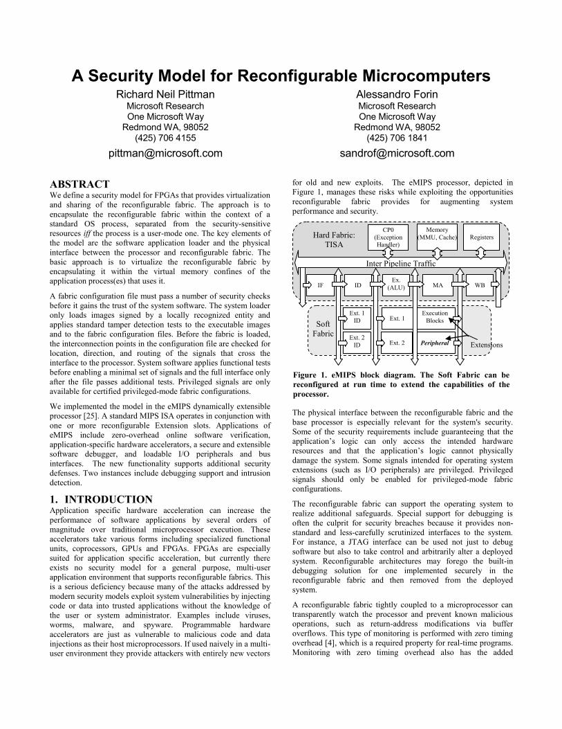
Figure 1. eMIPS block diagram. The Soft Fabric can be
reconfigured at run time to extend the capabilities of the
processor.
Page 4
advantage of rendering the monitor invisible to application code.
Other potential uses include code obfuscation, virus signature
detection and generation, software integrity verification via
Oblivious Hashing [5] and Integrity Checking Expressions[6], and
information flow control [7][8].
This paper describes the specific strategy implemented by the
eMIPS processor to enhance system performance and security
through integration of processor and reconfigurable fabric. The
issues encountered in the eMIPS processor are similar to those
encountered by other hardware acceleration architectures and the
solutions are therefore more generally applicable.
The rest of the paper is organized as follows. Section 2 provides
some pre-requisite information on the reconfigurable fabric
properties and the basic architecture of the microprocessor.
Section 3 defines the threat model for the architecture. Section 4
comprises the majority of the paper. It describes how the system is
implemented and how the loader enforces the threat model in both
software and hardware. Section 5 describes how the system
software enforces the model in the presence of interrupts and
exceptions. Section 6 describes how to leverage the architecture in
new security mechanisms. Section 7 presents our results to date
and the current project status. Section 8 surveys the related work
and Section 9 presents our conclusions.
2. BACKGROUND The eMIPS processor system provides a MIPS [1] RISC data path
tightly integrated with a configurable logic fabric. The eMIPS
processor prototype is implemented using a Xilinx Virtex 4 FPGA
[9] [10]. The Partial Reconfiguration feature (PR) of this FPGA
[11] allows the processor to dynamically change subsets of its
own logic, e.g. to partially reconfigure itself, while the rest of the
processor logic remains active. The fine-grained coupling between
processor and fabric provides maximum flexibility for hardware
acceleration. The eMIPS fabric applications include accelerating
application execution time, implementing plug and play on-chip
peripherals and bus interfaces, monitoring and model-checking
applications, and debugging of application software during
development. Uses of the eMIPS fabric are termed Extensions.
During the design phase of the PR tool flow, the hardware design
is partitioned and split into a static region and one or more
reconfigurable regions. The static and reconfigurable regions can
only connect at fixed physical locations in the FPGA fabric using
modules called Bus Macros. In the eMIPS case, the static region
implements the base processor and includes the Trusted ISA, or
TISA, the memory interface and the static peripherals. In a
product, this section would be realized in tamper-proof, non-
reconfigurable logic (such as in ASIC technology). The
reconfigurable regions are further subdivided into a number of
slots, called Extension slots. System software dynamically
allocates these Extension slots to implement application and
system modules called Extensions. In a product, they would be
realized in reconfigurable logic, such as in Embedded FPGA
technology. The actual PR process consists of writing a
configuration data file to the reconfiguration port, which is an 8-
bit or 32-bit parallel port included in the TISA design. The file is
the product of the PR tool flow. It contains a standard preamble,
commands to address specific locations in the FPGA fabric,
configuration data, and routing data. A simplified model for the
FPGA reconfiguration data plane is to view it as RAM, readable
and writeable only via the reconfiguration port.
Figure 1 is a logical block diagram of the eMIPS processor. The
Extension slots allow for acceleration of software applications by
replacing blocks of instructions that occur frequently within the
execution history of the application with specialized hardware that
can perform the same task more efficiently. In addition to
accelerating software, eMIPS Extensions provide capability for
transparently monitoring software [4] and for debugging [3].
Section 6 provides additional details on these features.
The eMIPS processor adds registers to the system coprocessor of
the MIPS ISA to allow software to control the state of the
interfaces between the TISA and each Extension slot. Controls are
both global (effecting all Extensions) and per-Extension. Using
these parameters, the system software may restrict an Extension to
user or kernel mode and disable/re-enable individual Extensions
when the system context switches between processes. MMLite,
the embedded RTOS for eMIPS [2] integrates these controls into
its application loader and scheduler. The basic approach is to
virtualize the reconfigurable fabric by encapsulating it within the
virtual memory confines of the application process(es) that uses it.
To guarantee system backward compatibility and function,
applications are developed in such a way as to continue to
function even if they do not receive an Extension slot.
3. THREAT MODEL The model considers a hardware or software component
trustworthy iff the system software has determined to the best of
its ability that the component poses no threat to the physical
system or its data. First, the component must come from a safe
source. Second, especially in the case of hardware components,
the component must not cause damage to the system or its data.
Finally, the component must not access resources it is not entitled
to or gather any unintended information.
When using hardware accelerators in a multi-user environment we
must guard system resources such as registers and memory from
corruption or access by malicious or malfunctioning accelerators.
In case the corruption is not preventable, mechanisms must be
available to system software to detect and recover from the
corruption. The eMIPS prototype is implemented as a soft-core on
an FPGA, and the processor data path and the hardware
accelerator reside on the same device. This configuration requires
additional care to protect the configurable fabric of the TISA
against tampering, as well as to prevent the creation of dangerous
circuits such as shorts (Figure 2a, 2b) and collisions (Figure 2d).
Each implementation of the eMIPS processor will have a floor
plan that defines the locations, sizes, shapes, and connection
points of the Bus Macros as shown in Figure 2. A design rules
checker (DRC) must determine if the fabric image fits within
these parameters. If a hardware image arbitrarily configures
frames outside the Extension slot (Figure 2e), it could change or
damage the functionality of the TISA in unpredictable ways. If
some required connection points do not route to the Bus Macros
(Figure 2c), the Extension will not function correctly. There are
attack vectors even inside the Extension. For instance, an attacker
could create a short by connecting a power line directly to ground,
thereby over-heating and eventually damaging the chip. The DRC
must catch these cases by scanning for circuit patterns in the
configuration bits before it is loaded onto the FPGA.
An Extension operating in User mode must not be able to access
privileged resources, or resources that belong to a different
process. Extensions can be restricted to a specific process or a
Page 5
thread within a specific process. Being able to control on a per-
thread basis provides valuable extra flexibility in some cases. The
operating system software running on the TISA must be able to
seamlessly modify the access parameters of each active Extension
in the eMIPS processor, without revealing global execution
patterns (the PCs of other threads) or system-wide parameters
(frequency of context switches and other scheduling parameters).
An Extension that recognizes an instruction opcode as its own
takes control of the execution, potentially stalling the TISA while
accessing registers and memory. An interrupt or exception can
occur while the Extension is stalling the TISA and before it has
completed its task. The system must recognize an interrupt in a
timely manner, which means that the Extension should be able to
clean up its state before returning control to the TISA. The system
must obfuscate the reason for the interruption to prevent snooping
of system-wide parameters. There exist established methods for
checking the trustworthiness of software application images,
usually by means of certified digests. We must extend those
methods to hardware application images as well. In some
instances, we must be able to defend against an attack that occurs
after software has validated the image.
Table 1: Summary of security checks.
Check Classification Section
Image Format, Security Signature, Software Checks 4.3
Compatibility, Dangerous Circuits, Configuration Boundaries
Hardware Checks 4.4
User or Kernel Mode, Per thread,
process or global
Mode and Scope 4.5
Sanity, Functional Discovery and
Verification
Functional
Verification
4.6
A number of attack vectors are specific to the application logic
and are presently too hard to detect in an online system, at least in
an efficient manner. A temperature-dependent oscillator [31] can
detect the load of a system and create a form of power-based
attack. An antenna-shaped circuit can send and/or receive an FM
signal. The signal goes outside the chip, but also potentially inside
the chip to a second Extension operating in a different security
context. Detecting the presence of these and/or similar circuits is
prohibitively complex. The synthesis tools complicate matters by
injecting a large degree of randomness in the appearance of the
configuration bit-streams. Simulated annealing is the preferred
method for place-and-route, with the result that a simple
recompilation of a design produces a potentially very different
(but still correct) result. This defies the use of virus-signatures e.g.
checksums and similar ways to uniquely identify a known
malicious file. The approach we take here is to use security
signatures to positively identify valid images, and we refuse to
accept non-signed or tampered images.
4. RTOS APPLICATION LOADER The RTOS is easily customizable and developers may adjust the
strictness of the security model enforced by the system according
to the needs of the target system. For the purpose of this paper, we
assume the strictest level of security. This section describes the
steps performed by the loader during secure image activation.
Table 1 summarizes the steps taken by the loader and the relevant
checks performed in the various loading phases. To the best of our
knowledge, this is the first secure loader for reconfigurable
hardware.
4.1 Secure Executable Images Application images on eMIPS can include both software and
hardware components. Figure 3 shows the Secure Executable (SE)
image format supported by the RTOS application loader. SE
images consist of four parts, which are ordered as follows:
software image (application code and data), hardware image
(Extension), security signature, and SE header. It is possible to
have an SE image with only a software or hardware image or
neither. The SE format does not specify what the format of the
software or hardware images is. The software image format of the
eMIPS processor is ELF. We currently generate software images
using a standard GCC compiler, targeted for a generic MIPS32
processor. Locating the SE header and other elements at the end
of the file provides backward-compatibility with the existing tools
that handle ELF images.
The hardware image format for an eMIPS Extension is currently
the Xilinx ACE file format. Included in the ACE file image are
the configuration bits for setting up the Extension hardware for
the desired function as well as the commands to write these bits to
the FPGA. The SE security signature varies according to the
desired security level; the SE image header indicates the type of
signature. Some possible options include a simple checksum, a
MD5 hash, SHA-1 hash, or SHA-256 hash. Security digests must
cover the entire file, including the SE image header. The digest is
independent of the format of the software or hardware images. At
the end of the SE image is the SE header. The SE header contains
a list of the images that precede it, the system configuration bits
for the Extension included in the SE image, and references to
other libraries that the application uses. The header lists the
properties of each Extension, which are only applicable after
reaching the appropriate level of trust. An Extension can be an
application accelerator, a user or kernel module, a local or global
module, a peripheral, or it needs privileged resources.
Figure 3. Format of the Secure Executable image file.
Figure 2. The Design Rule Checker tests an Extension before
it is loaded detect signals that are either (a,b) shorted (c)
unconnected (d) with a wrong direction or (e) do not connect
to a Bus Macro.
Page 6
SE images containing only software images have an advantage
over the ELF image alone. The SE image’s security signature is a
format independent authentication mechanism that can be used to
verify the source of the SE image and is the first line of security
against malicious attacks. SE images are produced using a simple
set of tools included in the RTOS distribution. Image signing
might require a public-key infrastructure and related tools.
When loading an SE image the application loader performs
checks on the images therein to verify the security digest and to
assess its level of trustworthiness. Before the loader configures an
Extension slot with an image it verifies the resource availability
(slot number and location), system compatibility (versioning), and
the safety of the image. Only after all these checks pass does the
application loader configure the Extension slot using the hardware
image. Note that the Extension is loaded but not immediately
enabled. After the hardware image is loaded, the application
loader tests it for minimal functionality against each configuration
parameter asserted for the Extension. If any of these tests fail, the
application loader removes the Extension and loading of the
application potentially fails. In the case of application and system
accelerators, the application will still work even without the
Extension, because the code the accelerator optimizes is still
present in the software image.
4.2 Initial State The power-up state of the system is precisely defined both for the
eMIPS prototype FPGA implementation and for a product level
implementation. To simplify the present exposition, we will
assume that the loader operates under the following initial
conditions: The TISA and any external peripherals have been
initialized, the RTOS has booted, it has initialized itself, and it is
ready to load the initial application. Proper serialization
guarantees that identical conditions apply if the user interface or
some other module requests image activation during normal
system operation. The configuration fabric of any unused
Extension slot (all of them at power-up time) is in an unknown
state. The states of signals from this region are unknown and
therefore the system cannot trust them. Therefore, all signals
between the empty Extension slots and the TISA are initially
gated off to prevent negative interference with the TISA. All
parameters for the Extension slot are initially de-asserted.
The RTOS receives a command to start an application from
permanent storage, which could be an embedded FLASH-based
file system, a compact-FLASH or a system disc, or a remote file
system over some communication medium. The RTOS invokes
the application loader and passes it the file location. The
application loader reads the entire file image into memory and
checks the file format. If the file image is not an SE image, the
application loader fails and returns an error. Since we are using a
high security setting for this model, the application loader would
also fail on an image that lacks a proper security signature.
4.3 Software Checks The application loader checks the security signature for validity
and source. The application loader ensures that the security
signature is valid and that the signature comes from a trusted
source. If the source of the SE image is not trusted or unknown to
the system, the loader fails and returns an error. After determining
the trustworthiness of the source of the application image, the
loader checks the contents of the image for potential tampering,
using the security digest. If none of the images in the SE file
requires special privileges the loader is satisfied and proceeds to
the next step. We describe special cases in Sections 4.8 and 4.9.
4.4 Hardware Checks eMIPS can work with many of the different FPGA devices that
are available on the market, but the properties of the Extension
slots on one device are most likely quite different from those on a
different device. Even on the same device, there can be different
implementations or revisions of the eMIPS architecture, with
different geometry and/or interface specifications. Before a
hardware image for an Extension is loaded, the application loader
must verify that the hardware image is compatible with the FPGA
used in the target system. Preliminary checks include the device
type, stepping, and system versioning data.
Even after the preliminary tests pass, the system still does not trust
that the hardware image is safe to use. As indicated in Section 3,
the hardware images configure the routing and logic of the FPGA
fabric, and there exist known configurations that can damage it or
produce unpredictable results. The loader uses a design rules
checker (DRC) to scan the hardware image and to detect such
damaging configurations. The configuration data for of the
hardware image is a binary file that represents the functions of
logic elements and the routing between them.
Searching for binary patterns or signatures in the image is a
common method for detecting malicious code such as viruses in
software. This method is not as effective for hardware images.
Compilation of software images from source code is mostly a
deterministic process, whereas hardware synthesis is not.
Hardware images are synthesized into logical netlists, mapped to
the functional units available and signals routed between the
functional units. This process is NP-hard and thus performed
using heuristic algorithms. Typically, simulated annealing
algorithms place and route the mapped logic and minimize
parameters such as speed and area. Simulated annealing
incorporates random moves to prevent the process from settling
into valleys along the optimization space. The process is therefore
not deterministic and the results vary from run to run. For this
reason, the binary encoding of a circuit can vary widely, and
searching for an instance of a dangerous circuit in a hardware
image is a computationally expensive problem.
One efficient way to search hardware images for dangerous
circuits is to use a higher level of abstraction. Software can
extract the logic and routing information from the hardware
configuration image. Using this information we can reconstruct a
circuit graph equivalent to the synthesized net lists originally used
to implement the hardware image. Using the circuit graph, the
DRC traces the hardware image for sub graphs that match patterns
in a database stored on the system, If at any time the DRC detects
a sub graph that is identified as dangerous the application loader
throws a violation and exits the application. Potentially dangerous
circuits that the DRC could encounter and are easy to detect
include but are not limited to output connected to output
(collision), input connected to input (floating signal), and power
signals connected directly to ground (short).
Implementations of the eMIPS processor have a specific floor
plan that fixes the locations, sizes, shapes, and connection points
through the Bus Macros. The DRC uses this geometry information
to determine the compatibility of the hardware to the target
system. The DRC scans the configuration frame addresses and
verifies that the configuration image only modifies the region of
Page 7
the targeted Extension slot (i.e. no frames outside the Extension
slot are modified). Using the circuit graph again, the DRC checks
that the connection points can only route via the Bus Macros. If
the DRC detects any violation of the geometric constraints, the
application loader will not load the hardware image but this is not
a fatal error. If the software images passes the remaining checks,
the application will still be loaded, but without hardware support.
4.5 Mode and Scope of an Extension The current state of the Extension interface is defined by the
privilege mode (User versus Kernel) and scope (Local to a process
or Global) and by the current mode and process executing on the
TISA. From these we can derive four accelerator classes: Local
User (LU), Global User (GU), Local Kernel (LK), and Global
Kernel (GK). Both LU and GU Extensions can only operate while
the processor is in user mode. LU is further restricted to a given
thread or process while GU is active across all user processes and
threads. LK and GK are restricted to kernel mode, LK is restricted
to specific kernel mode threads or processes and GK is not.
LU Extensions are application specific Extensions shipped with
the application and loaded when the application is loaded on the
target machine. GU Extensions are shared libraries of general-
purpose operations that any user application can invoke to
accelerate performance. Likewise, LK Extensions are Extensions
included as part of a specific kernel services such as a network
stack accelerator. GK Extensions support the base OS services
such as interrupt service routines or scheduling. The plug-and-
play on-chip peripherals are GK class Extensions and are further
discussed in Section 4.8. A SE image that requests any Kernel or
Global privilege will only load successfully if the security
signature warrants that assignment. In practice, most Extensions
will be LU type Extensions.
4.6 Functional Verification Once the Extension passes all static tests, the application loader
streams the configuration and command bits to the FPGA
configuration port. Note that there exist devices on the market that
will perform tamper-detection of the configuration stream in
hardware, using AES signatures and/or encryption. These devices
will defeat attacks timed at this stage of the loading process. After
it sent the last byte of the configuration stream, the application
loader must wait a small number of cycles for the FPGA to
complete the re-configuration process. The application loader
enables the clock to the target slot and a single wire, called the
PRESENT signal, connecting the slot to a lock module. The state
of the signals that cross the TISA/Extension interface is as
depicted in “Slot 1” in Figure 4. The application loader sets the
key to the lock and the lock listens to the wire from the Extension.
The Extension must demonstrate its viability by modulating the
signal according to the required key. If the lock does not report a
match by the deadline, the Extension must be malfunctioning. A
malfunctioning Extension is immediately unloaded.
If it finds a match, the lock notifies the application loader through
an interrupt from a system peripheral called the Extension
Controller. The Extension Controller module acts as an
intermediary between system software and the active but not-yet
trusted Extension; it is described with more details elsewhere [12].
Extensions contain an interface to permit interrogation by the
system software through the Extension Controller. During this
stage of application loading, connections to the memory bus by
the Extension continue to be gated off except when it is
communicating to system software through the Extension
Controller. The control signals that interface the Extension to the
memory controller and the Extension Controller are depicted in
Figure 5. One Extension Controller configures all the Extensions,
using multiple sets of such control signals.
Each Extension declares its functionality and its resource
requirements via a set of standard registers, accessible only via the
Extension Controller. When software tries to read this information
from the Extension, the Extension Controller raises the
BAT_Enable signal, allowing the Extension to temporarily “see”
the request on the memory bus and respond to it. The Extension
Controller removes the BAT_Enable signal once the Extension
places the data on the memory bus and raises the Done signal. A
timeout can override the Done signal to prevent the memory bus
from locking-out when there is no Extension present, or in case a
malicious or misbehaving Extension tries to obtain and retain
control of the bus. The same procedure applies when software
writes to the Extensions registers to assign resources. Therefore,
during the entire configuration, only the Extension Controller can
grant access to the memory bus to the Extension, and for a single
transaction. The Extension itself is not able to take control of the
bus.
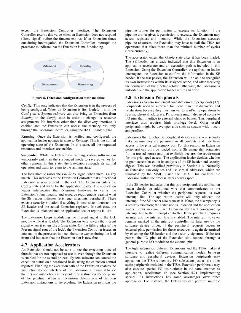
The Extensions can be in one of the four states shown in the state
machine of Figure 6. The application loader sets the initial state of
the Extension; other system software such as a device driver can
modify it later on, but only via the Extension Controller. The
states are as follows:
Absent: The Extension is not present. This means that the
Extension was never loaded or that it was removed. In the latter
case, the Extension might still be present in the Extension slot. An
Extension in the absent state will not respond to any interface
Figure 5. Extension interfaces to the memory controller and to
the extension controller
Figure 4. The interface signals between TISA and Extension
are selectively enabled, according to the current level of trust
and the required functionality.
Page 8
except the Extension Controller interface. The Extension
Controller returns this value when an Extension does not respond
(Done signal) before the timeout expires. If an Extension times
out during interrogation, the Extension Controller interrupts the
processor to indicate that the Extension is malfunctioning.
Config: This state indicates that the Extension is in the process of
being configured. When an Extension is first loaded, it is in the
Config state. System software can also bring an Extension from
Running to the Config state in order to change its resource
assignments. No interface other than the discovery interface is
enabled and the Extension can access the memory bus only
through the Extension Controller, using the BAT_Enable signal.
Running: Once the Extension is verified and configured, the
application loader updates its state to Running. This is the normal
operating state of the Extension. In this state, all the requested
resources and interfaces are enabled.
Suspended: While the Extension is running, system software can
temporarily put it in the suspended mode to save power or for
other reasons. In this state, the Extension suspends its normal
operation and waits to return to the running state.
The lock module raises the PRESENT signal when there is a key
match. This indicates to the Extension Controller that a functional
Extension is now present in the slot. The Extension enters the
Config state and waits for the application loader. The application
loader interrogates the Extension hardware to verify the
Extension’s functionality and resource requirements against what
the SE header indicates (privilege, interrupts, peripheral). There
exists a security violation if anything is inconsistent between the
SE header and the actual Extension registers. In such case, the
Extension is unloaded and the application loader reports failure.
The Extension keeps modulating the Present signal to the lock
module while it is loaded. The Extension only lowers the Present
signal when it enters the Absent state. On the falling edge of the
Present signal (out of the lock), the Extension Controller issues an
interrupt to the processor in much the same way as during the load
event and indicates that the Extension slot is now free.
4.7 Application Accelerators An Extension should not be able to see the execution trace of
threads that are not supposed to use it, even though the Extension
is enabled for the overall process. System software can control the
execution status on a per-thread basis, using the extension control
registers. Enabling the execution path of the Extension enables the
instruction decode interface of the Extension, allowing it to see
the PCs and instructions as they enter the instruction decode phase
of the pipeline. When an Extension detects one of its own
Extension instructions in the pipeline, the Extension petitions the
pipeline arbiter for permission to execute its function. If the
pipeline arbiter gives it permission to execute, the Extension may
access registers and memory. While the Extension accesses
pipeline resources, the Extension may have to stall the TISA for
operations that takes more than the minimal number of cycles
(three currently).
The accelerator enters the Config state after it has been loaded.
The SE header has already indicated that this Extension is an
application accelerator and an execution path is included in this
Extension. Using the Extension Controller, the application loader
interrogates the Extension to confirm the information in the SE
header. If the test passes, the Extension will be able to recognize
its own instructions within its assigned scope, and after receiving
the permission of the pipeline arbiter. Otherwise, the Extension is
unloaded and the application loader returns an error.
4.8 Extension Peripherals Extensions can also implement loadable on-chip peripherals [12].
Peripherals need to interface for more than just discovery and
verification because they must answer to read/write operations to
specific physical addresses. Peripherals might also need access to
I/O pins that interface to external chips or busses. This peripheral
interface thus requires high privilege level. Other useful
peripherals might be developer aids such as system-wide tracers
and profilers.
Extensions that function as peripheral devices are severe security
risks because they are persistent in all contexts, and they have
access to the physical memory bus. For this reason, an Extension
peripheral can only be loaded from a SE image that originates
from a trusted source and that explicitly declares the requirement
for this privileged access. The application loader decides whether
to grant access based on its analysis of the SE header and security
digest. This was described previously in Section 4.1. Normally
an Extension can only see and use virtual addresses, which are
translated by the MMU inside the TISA. This confines the
Extension within the process’ user address space.
If the SE header indicates that this is a peripheral, the application
loader checks an additional wire that communicates to the
Extension Controller whether the peripheral requests its own
interrupt line. The application loader will only allocate the
interrupt if the SE header also requests it. If not, the discrepancy is
a security violation; the Extension is unloaded and the application
loader throws an error. Each Extension slot has a corresponding
interrupt line to the interrupt controller. If the peripheral requires
an interrupt, the interrupt line is enabled. The interrupt however
remains masked in the interrupt controller for later use by the
software device driver. If the peripheral requests access to
external pins, permission for those resources is again determined
by checking the SE header and the security signature. If the test
passes, the I/O pins of the Extension slot connect through a
general-purpose I/O module to the external pins.
The tight integration between Extensions and the TISA makes it
possible to realize different communication models between
software and peripheral devices. Extension peripherals may
appear on the TISA’s memory I/O subsystem just as the other
static peripherals included in the TISA. Extension peripherals may
also execute special I/O instructions; in the same manner as
application, accelerators do (see Section 4.7). Implementing
special I/O instructions has some advantages over other
approaches. For instance, the Extensions can perform multiple
Figure 6. Extension configuration state machine
Page 9
register and memory operations before returning control of the
data path to the TISA. Consequently, an Extension can execute
atomic operations involving several registers or memory
addresses without disabling interrupts and without exposing the
physical memory bus.
Table 2: Peripheral Base Address Translation Table.
Size (bytes) Starting Address Address Valid
Size 1 Address 1 1
Size 2 Address 2 0
… … …
Size n Address n 0
If the Extension peripheral interfaces to software via the memory
bus, the Extension requires insertion into the I/O memory map.
For Extension Peripherals, the registers used in the discovery
phase of the application loader include the Base Address
Translation (BAT) table shown in Table 2. Each BAT entry
contains a base address and a size that defines a range of
addresses reserved for the Extension in the physical memory map,
and a valid flag. Each peripheral on the memory map has at least
one entry for a control region. Interfaces such as a SRAM
controller indicate two ranges: a 32-byte range for the control
region and a separate range for the SRAM proper. The size is
read-only; it provides the memory space requirement during
configuration. The application loader selects a free range and
writes the Start Address in the BAT entry.
When the Extension is active, the memory bus interface is enabled
and the Extension watches the addresses on the memory bus and
compares them to its BAT entries. If there is a match, the
Extension completes the read/write transaction.
Interfacing peripherals via the memory bus has the advantage of
allowing for better software reuse because existing device drivers
can more easily port to the new peripheral. Additionally, the
memory-mapped interface does not entail the cost of allocating
opcodes to an Extension with global scope, thereby reducing the
number of available opcodes.
4.9 Extensions as Shared Libraries Many software image formats support shared libraries; they
represent in one form or another external dependencies, e.g.
dependencies on software modules that are provided separately.
We extend this concept to hardware Extensions, using the idea of
treating the full SE image in the same way software treats an ELF
image. In other words, the dependent shared library is in turn an
SE image, with or without Extension images in it. The loader
loops through the tree of dependents. If any fails to load the
application as a whole fails to load. Actual sharing of Extensions
across processes however does create potential security risks.
Only stateless Extensions can safely be shared in this way. Since a
DRC checker cannot verify this rule, we have to rely on the
security signature alone. An Extension that is intended for sharing
must be marked safe at the highest security level, even though it
might operate in User mode only.
Once all dependents are loaded and activated the application is
ready to start executing. The application loader creates a new
thread, with the appropriate values for the extension control
registers. When the scheduler activates the thread, its state is
loaded and at the first RFE instruction, the extension control bits
take effect, bringing the context in effect. While the Extension is
in scope, the state of the signals that cross the TISA/Extension
interface are as depicted in “Slot 2” or “Slot 3” in Figure 4,
depending on the Extension type. The scheduler enables and
disables these interfaces as the Extension enters and exists scope.
5. EXCEPTIONS AND EXTENSIONS In the eMIPS processor, the active state of the Extension slots is
treated in the same way as interrupts are handled in a traditional
MIPS processor. It may be necessary to disable all user
Extensions very quickly, such as when the processor switches
from user mode to kernel mode upon an interrupt or exception.
These Extensions are re-enabled when the processor returns to
user mode after software has serviced the interrupt or exception.
Kernel Extensions become active when the processor is in kernel
mode and disabled when the processor enters user mode unless
the Global parameter is set (i.e. a GK Extension).
An interrupt or exception might stop an Extension in the middle
of an operation. When this occurs, the Extension has a limited
opportunity to complete any pending write-backs to the register
file and to report its virtual location in the basic block it is
accelerating, before the TISA forcibly resumes control. After a
maximum number of cycles expires, all user mode Extensions are
deactivated, the mode is changed in the processor status register,
kernel Extensions are activated, and the processor restarts
execution at the proper exception vector. See [32] for more
details.
Allowing Extension hardware to stall the processor and then force
it to release it on interrupts and exceptions creates a possible
secondary attack vector. An application can include an Extension
that stalls the pipeline whenever it enters its process and only
releases it when an interrupt context switches the processor.
Counting the cycles spent in the Extension can reveal the
frequency of interrupts. From that information, the attacker can
deduce other critical data, such as keystrokes on a keyboard.
The frequency of interrupts can be obfuscated using random
intervals to generate spurious interrupts. This cancels Extension
operations just as a real interrupt would, but context switches back
to the same process. In this way, a malicious Extension spying on
the system cannot be sure if the cancelation was a real interrupt or
a random cancel. If the minimum interval is sufficiently large, it
will have little impact on most legitimate Extensions.
6. AUGMENTED SECURITY Reconfigurable microprocessors such as eMIPS and Stretch [13]
provide new opportunities to improve security. In this section, we
describe two ideas that we have implemented on eMIPS, and
indicate other future work.
6.1 eBug: a Reconfigurable, On-Demand, Per
Process Debugger Most embedded microprocessors ship with some type of
embedded hardware debugging support. Often this consists of a
serial interface such as JTAG that links to a debugger such as
GDB or other UI. This debugging is important to system
developers for identifying and correcting software defects before
the release of the system, but it also provides to an attacker a
wealth of information about the system behavior and parameters.
Embedded hardware debuggers are global debuggers, meaning
that all threads, processes, and modes are visible. They can
arbitrarily access memory and other system resources and
Page 10
therefore create a security hole. A JTAG debugger is also a
physical threat in a shipping product. An attacker only has to
connect a JTAG cable to gain complete control of the system.
The eMIPS processor differs from other processors in that it ships
with no embedded hardware debugging support. That is not to say
it does not have a debugger. Included with the eMIPS processor
release is a debugging Extension, eBug [3]. eBug can be loaded
into an Extension slot during application debugging and then
removed when the system is ready for release. In a released
system, the physical pins used by the debugger are left floating,
and an attacker will gain nothing by gaining physical access to
them. eBug is not signed and can only be loaded on an RTOS with
a low security setting. Therefore, an attacker that wants to use the
debugger to gather information surreptitiously must overcome
first the application loader.
Another advantage provided by eBug is that it is a per-process
debugger, with a user-local scope. This means that even if an
attacker loads eBug, the debugger only sees local information
about the process connected to it and nothing else. The RTOS
hides all the other processes by disabling eBug whenever it de-
schedules the process, and enabling it again when it reschedules it.
By restricting the debugger to a single process context, eMIPS
eliminates the risk of using the embedded debugger as an attack
vector.
6.2 P2V: Security through Zero-Overhead
Assertion Checking The P2V compiler [4] generates hardware Extensions for the
eMIPS processor useful for assertion-based verification of
application software. The Extensions monitor passively the
internal register and memory busses, looking for violations to the
given assertions. The monitors operate strictly within the scope of
their process and do not interfere with the running application.
They do not change the execution flow in any case, and do not
even change the timing behavior in any case of practical interest.
The software running on the eMIPS processor is not aware of the
monitor; P2V requires no changes to it. When the monitor detects
a violation, it can throw an exception to launch a debugger, or to
terminate the application. Other behaviors are possible.
Many of the assertions used to detect bugs in an application are
useful to detect security attacks on the system. System developers
can ship a security monitor generated from assertions targeted at
known attacks. The monitor is loaded at system boot time and
never unloaded. Then as analysts identify new threats, developers
can release a new version of the monitor along with their system
patches and updates.
Using P2V, we have developed monitors to detect stack-smashing
attacks, as shown in Figure 8. In the experiment, we deployed a
simple but erroneous program on the eMIPS. The program reads
data from the console and copies it to an array on the program
stack, without bounds checking. As the user continues to type, the
array pointer goes outside the bounds of the array and eventually
overwrites the return address stored on the stack. The monitor
loaded in the Extension slot checks the PSL assertion
"never($writing == $return)", which states that the return address
of a function should never be overwritten. When the program
eventually does overwrite the return address, the monitor detects
the violation and throws an exception.
Also of interest is the stealthy manner in which these monitors
operate. Because they do not affect the timings of the application
and execute in an isolated hardware unit, they are not detectable
by an attacker e.g. via timing attacks. The monitors can also be
used to trace the source of the security violation to a specific
process or thread.
6.3 Other Opportunities Additional applications of the eMIPS architecture to security
include, but are not limited to, code obfuscation, virus signature
detection and generation, software integrity verification via
Oblivious Hashing [5] or Integrity Checking Expressions[6], and
information flow control [7][8]. The use of extension instructions
can aid in code obfuscation since the extension opcodes are
undefined and they have different meanings in different
applications, possibly even for different threads in the same
process. The Extension can randomly choose to recognize the
instruction or not to make reverse engineering even more difficult.
Virus signatures currently rely on static code sequences alone. An
Extension can additionally rely on dynamic code sequences and
on specific data values in registers. A stack-smashing detector can
save, for instance, the last few instructions executed to create or
recognize this virus's dynamic signature, with zero-overhead and
completely stealthy behavior. It can also check and modify the
arguments to a call to a memory copy function to detect and
prevent buffer overflows. Software integrity checking as in
Oblivious Hashing, Integrity Checking Expressions, and related
techniques prevents code tampering by verifying code integrity
during execution. This usually involves two software parties
periodically checking each other's integrity and generating a
degraded system behavior when they detect a violation. The two
parties of a challenge-response based scheme could be
implemented one in software (the TISA) and one in hardware (the
Extension), with the added benefit that the hardware component
can be neither detected nor altered by the attacker. In information
flow control, an Extension can help by isolating the tags attached
with data and make them tamper-proof.
7. STATUS AND RESULTS The baseline eMIPS processor has been available since December
2007 on the Microsoft Research Embedded and Reconfigurable
Systems Group website [25]. The release includes full source and
is free for academic and non-commercial use.
Figure 8. The FPGA fabric can perform intrusion detection.
A Monitor watches the CPU transactions and detects
attempts to over-write the return address.
Page 11
Table 3: Resource Utilization by Extensions
LX25 SX35
EXT Total % EXT Total %
SLICES 1,536 10,752 14.3 4,864 15,360 31.6
DSP48 2 48 0.5 64 192 33.3
BRAMS 3 72 0.5 64 192 33.3
The application loader is integrated into the MMLite embedded
operating system [2], which is also available on the group website.
The release on the MMLite OS is accompanied with utilities for
generating SE file images from ELF binaries and Xilinx ACE
files. The MMLite scheduler handles the state of the Extension
interfaces as the processes and threads context switch in and out
of scope.
Table 4: TISA Resource Utilization
Resources 1 Extension 2 Extensions % Increase
Slice 7862 9180 14.4
BRAMs 8 8 0
DSPs 40 40 0
The December release supports the ML401 and Virtex 4 LX25
devices. We have recently ported eMIPS to the ML402 and Virtex
4 SX35. Using the additional resources provided by the SX35,
the processor now includes two Extension slots as opposed to only
one in the LX25. Work continues in both implementations to
further optimize the design for speed and area. In the Virtex 4
SX35, we are able to increase the area allocated to the Extensions
by over three times compared with the LX25. The availability of
functional units such as BRAMs and DSPs will vary with the
location and shape of the extension slots. Table 3 provides a
breakdown of the resources available for Extension
implementations in the two chips.
The Extension area may be subdivided in any number of slots, but
in practice, there are limiting factors. There is a minimum area
required to implement the Extension interface inside the slot, and
the region perimeter must be of sufficient length to place all the
required Bus Macros. Replicating the Extension interface logic
for multiple Extensions incurs some additional overhead as well.
The size of the TISA grows by about 15 percent as shown in
Table 4. Here we compare two designs for the same target SX35
device. The first uses one slot, the second two slots.
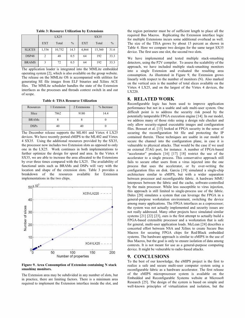
We have implemented and tested multiple stack-smashing
detectors, using the P2V compiler. To assess the scalability of the
approach, we have included multiple stack-smashing monitors
into a single Extension and evaluated the resulting area
consumption. As illustrated in Figure 9, the Extension grows
linearly with respect to the number of monitors (N). Also marked
on the vertical axis is the number of total slices available on the
Virtex 4 LX25, and on the largest of the Virtex 4 devices, the
LX220.
8. RELATED WORK Reconfigurable logic has been used to improve application
performance but not in a usable and safe multi-user system. One
difficult point is to address the security risk posed by the
potentially tamperable FPGA execution engine [14]. In our model,
we address many of those risks using a design rule checker and
only allow security-signed executable images and configuration
files. Bossuet et al. [15] looked at FPGA security in the sense of
securing the reconfiguration bit file and protecting the IP
contained therein. These techniques are usable in our model to
secure the channel into the configuration plane, in case it is
vulnerable to physical attacks. That would be the case if we used
an external JTAG port, for instance. A number of FPGA-based
“accelerator” products [16] [17] [18] restrict the use of the
accelerator to a single process. This conservative approach still
fails to secure other users from a virus injected into the one
process that uses the accelerator, or by over-writing the
configuration files on disk. Garcia [19] simulated a single-chip
architecture similar to eMIPS, but with a wider separation
between processor and reconfigurable fabric. A hardware MMU
interposes between the fabric and the cache, software-controlled
by the main processor. While less susceptible to virus injection,
this approach is still limited to single-process use of the fabric.
Dales [20] simulates a system that can leverage the FPGA in a
general-purpose workstation environment, switching the device
among many applications. The FPGA interfaces as a coprocessor;
the system was not actually implemented and security issues are
not really addressed. Many other projects have simulated similar
systems [21] [22] [23], ours is the first attempt to actually build a
FPGA-based extensible processor and a workstation that is safe
for general, multi-user application loads. McLean [24] describes a
concerted effort between NSA and Xilinx to create Secure Bus
Macros for securing FPGA chips for Red/Black embedded
systems. The hardware approach is similar to eMIPS in the use of
Bus Macros, but the goal is only to ensure isolation of data among
contexts. It is not meant for use as a general-purpose computing
device. It might be vulnerable to radio-based attacks.
9. CONCLUSIONS To the best of our knowledge, the eMIPS project is the first to
realize a safe and secure multi-user computer system using a
reconfigurable fabric as a hardware accelerator. The first release
of the eMIPS microprocessor system is available on the
Embedded and Reconfigurable Systems website at Microsoft
Research [25]. The design of the system is based on simple and
well-known principles of virtualization and isolation, but the
Figure 9. Area Consumption of Extension containing N stack
smashing monitors.
Page 12
practical realization of those principles has been anything but
simple. Ensuring that hardware images are safe to use is a difficult
proposition, which required the use of a design rule checker at
runtime and careful, gradual exposure of the hardware signals
during image activation.
We have experimented with a number of different scenarios, from
application acceleration to loadable on-chip peripherals, from
loadable hardware debugging support to zero-overhead online
model checking. In all cases, we were able to exploit the
reconfigurable fabric without compromising security. In fact, we
were able to identify a number of new ways in which the
architecture can improve the overall security of the system. Of
special interest is the ability to insert stealthy monitors for
intrusion detection, such as stack-smashing detectors, to run on
the reconfigurable fabric to monitor the execution of the base
processor.
ACKNOWLEDGEMENT
The authors would like to thank the members of the security
research group at MSR and the anonymous referees for their help
in improving this paper. Special thanks to J. Carver for his work
on the DRC and the SX35 devices.
10. REFERENCES [1] Kane, G., Heinrich, J. 1992. MIPS RISC Architecture.
Prentice Hall, Upper Saddle River, NJ.
[2] Download at http://research.microsoft.com/invisible/
[3] Busonera, G., Forin, A., Pittman, R., N. 2008. Exploiting
partial reconfiguration for flexible software debugging.
SAMOS-VIII.
[4] Lu, H. and Forin, A. 2008. Automatic Processor
Customization for Zero-Overhead Online Software
Verification. To Appear on Transactions on VLSI,
November 2008.
[5] Chen, Y., et al. 2002. Oblivious Hashing: A Stealthy
Software Integrity Verification Primitive. 5th International
Workshop on Information Hiding, LNCS 2578, pp. 400-414.
[6] Jakubowski, M. et al. 2007. Software integrity checking
expressions (ICEs) for robust tamper detection. Information
Hiding '07, Saint Malo, France.
[7] Dalton, M., Kannan, H., Kozyrakis, C. 2007. Raksha: a
flexible information flow architecture for software security.
SIGARCH News, Vol 35.2, May 2007, pp. 482-493.
[8] Zeldovich, N. et al. 2006. Making Information Flow Explicit
in HiStar. Usenix Symposium on Operating System Design
and Implementation.
[9] Xilinx Virtex 4 Family Overview. Xilinx Inc., June 2005.
Available at
http://direct.xilinx.com/bvdocs/publications/ds112.pdf
[10] Xilinx. Virtex-4 Development Boards. Xilinx Inc., 2005. At
http://www.xilinx.com/products/silicon_solutions/fpgas/virte
x/virtex4/index.htm
[11] Xilinx Development System Reference Guide, Chapter 5,
Partial Reconfiguration. Xilinx Inc., December 2005, pp.
113-140, Available at
http://toolbox.xilinx.com/docsan/xilinx8/books/docs/dev/dev.
pdf
[12] Bharat, S., Forin, A., Pittman, R. N. 2008. Extensible On-
Chip Peripherals. SASP’08, Symposium on Application
Specific Processors, Anaheim CA.
[13] Stretch, Inc.2006. http://www.stretchinc.com
[14] Hadžić, I., Udani, S., Smith, J. M. 1999. FPGA Viruses.
FPLA’99, pp. 291-300.
[15] Bossuet, L., Gogniat, G., Burleson, W. 2006. Dynamically
Configurable Security for SRAM FPGA Bitstreams.
International Journal of Embedded Systems.
[16] Mitrionics, Inc. 2001. http://www.mitrionics.com
[17] SRC Computers Inc.1996. http://www.srccomp.com
[18] Tarari, Inc. 2002. http://www.tarari.com
[19] Garcia, P. and Compton, K. 2007. A Reconfigurable
Hardware Interface for a Modern Computing System.
FCCM’07, Napa Ca. pp.73-84.
[20] Dales, M. 2003. Managing a Reconfigurable Processor in a
General Purpose Workstation Environment. DATE ’03.
[21] Hauser, J. R., Wawrzynek, J. 1997. Garp: A MIPS Processor
with a Reconfigurable Coprocessor. FCCM’97 pp. 12-21.
[22] Lysecky, R., Stitt, G., Vahid, F. 2006. Warp Processors.
DAES Transactions, pp. 659-681.
[23] Wittig, R. D., Chow, P. 1996. OneChip: An FPGA Processor
with Reconfigurable Logic. FCCM’96, pp. 126-135.
[24] McLean, M. and Moore, J. 2007. FPGA-Based Single Chip
Cryptographic Solution. In Military Embedded Systems,
March 2007.
[25] Download at
http://research.microsoft.com/research/EmbeddedSystems/e
MIPS/emips.aspx
[26] Athanas, P., Silverman, H. 1993. Processor Reconfiguration
through Instruction-Set Metamorphosis. Computer Vol. 26,
March 1993, pp. 11-18.
[27] Davidson, J. 1993. FPGA Implementation of a
reconfigurable microprocessor. CICC’93.
[28] Lau, D., Pritchard, O., Molson, P. 2006. Automated
Generation of Hardware Accelerators with Direct Memory
Access from ANSI/ISO Standard C Functions. FCCM’06,
pp. 45-54.
[29] Kelm, J., H. and Lumetta, S., S. 2008. HybridOS: Runtime
Support for Reconfigurable Accelerators. FPGA ’08,
Monterey CA. pp. 212-221.
[30] Rowen, C, Maydan, D. 2001. Automated Processor
Generation for System-on-Chip. ESSCIRC’01.
[31] Lopez-Buedo, S, Garrido, J., Boemo, E. I. Dynamically
inserting, operating, and eliminating thermal sensors of
FPGA-based systems. IEEE Transactions on Components
and Packaging Technologies, Volume 25, Dec 2002, pp. 561-
566.
[32] Sekar, A. and Forin, A. 2008. Automatic Generation of
Interrupt-Aware Hardware Accelerators with the M2V
Compiler. Microsoft Research Technical Report MSR-TR-
2008-110, August 2008.


![Music, Mathematics, and Microcomputers · Music, Mathematics, and Microcomputers ... and elaborated by Knud Jeppesen [12]. ... melodic, and counterpoint rules, is it](https://static.documents.pub/doc/80x56/5b4913d27f8b9ab1228b5150/music-mathematics-and-microcomputers-music-mathematics-and-microcomputers.jpg)


