44
A Segment Routing (SR) Tutorial R. Bonica NANOG70 June 6, 2017

A Segment Routing (SR) Tutorial
R. Bonica NANOG70
June 6, 2017
AKA: SPRING
• IETF Standardization – Source Packet Routing In Networking
(SPRING) WG – ISIS, OSPF, IDR and MPLS WGs

What is SR? • A tunneling technology
– Encapsulates a packet within a header – Forwards packet based upon encapsulating header
• A Traffic Engineering (TE) technology – Allows a router to steer traffic along an SR path – Path can be different from the least cost path
• Maybe more? – Innovative new applications to be discovered

Terminology • An SR domain is a collection of SR capable
devices – Roles: Ingress, transit, egress – May be mixed with non-SR-capable transit devices
• An SR Path – Connects an SR ingress to an SR egress – Can be different from the least cost path – Contains one or more SR Segments

More Terminology • An SR Segment
– Connects two points within the SR domain – Can traverse one or more router hops – Is represented by a Segment Identifier (SID)
• A Segment Identifier (SID) – Identifies the path fragment that the packet follows – Can have node-local or domain-wide (a.k.a., global)
significance

Pictorial Terminology
Ingress Egress Segment A
Segment C
SR Path
SR Domain

SR TRAFFIC ENGINEERING

Traditional TE Approaches • Encode path information in the packet
– Packet header enumerates every hop in the path – No path information stored in the network – Example: IPv4 with Strict Source Routing Option
• Store path information in the network – Packet header contains exactly one path identifier – No further path information is encoded in the packet – Example: RSVP-signaled MPLS
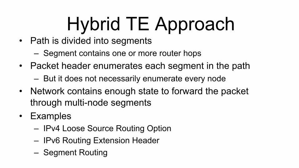
Hybrid TE Approach • Path is divided into segments
– Segment contains one or more router hops • Packet header enumerates each segment in the path
– But it does not necessarily enumerate every node • Network contains enough state to forward the packet
through multi-node segments • Examples
– IPv4 Loose Source Routing Option – IPv6 Routing Extension Header – Segment Routing

The SR TE Approach • SR defines multiple segment types
– Some types traverse one router hop – Some types traverse multiple router hops
• SR header enumerates each segment in the path – But not necessarily each node
• Network contains enough information to route a packet through a multi-hop segment

Basic Segment Types • Adjacency (single router hop)
– Represents an IGP adjacency
• Prefix (one or more hops) – Represents IGP least cost path to a prefix
• Anycast (one or more hops) – Represents IGP least cost path to a non-unique prefix
• Binding – Represents a tunnel (e.g., RSVP-signaled LSP)
Additional Segment Types
• Additional segment types are being proposed – Support new SR applications
• In this tutorial, we will focus on prefix and adjacency segments
• Gentle introduction to anycast and binding segments
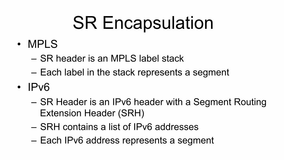
SR Encapsulation • MPLS
– SR header is an MPLS label stack – Each label in the stack represents a segment
• IPv6 – SR Header is an IPv6 header with a Segment Routing
Extension Header (SRH) – SRH contains a list of IPv6 addresses – Each IPv6 address represents a segment

MPLS FORWARDING

Local Labels
• Some SIDs have node-local significance – Nodes automatically allocate local SIDs from a free
pool – Nodes map local SIDs to local labels – No need for domain-wide co-ordination – Example: SIDs representing adjacency segments

R1-R4: Adjacency Segments
R1 R2 R3
R7
R4 R5 R6
R1 IGP advertisement Local label:81, link to R2 Local label:82, link to R4
R2 IGP advertisement Local label:81, link to R1 Local label:82, link to R3 Local label:83, link to R5
R3 IGP advertisement Local label:81, link to R2 Local label:82, link to R6 Local label:83, link to R7
R7 IGP advertisement Local label:81, link to R3 Local label:82, link to R6
R4 IGP advertisement Local label:81, link to R1 Local label:82, link to R5
R5 IGP advertisement Local label:81, link to R2 Local label:82, link to R4 Local label:83, link to R6
R6 IGP advertisement Local label:81, link to R3 Local label:82, link to R5 Local label:83, link to R7
82 82 82 pay load
83 82 82 82 pay load
82 82 pay load pay
load
82 pay load
82 83 82 82 82 pay load
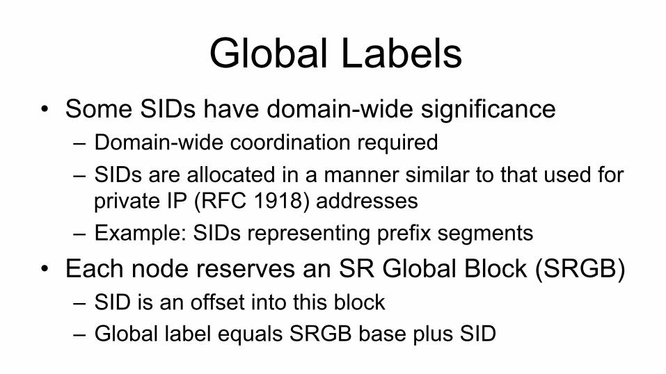
Global Labels • Some SIDs have domain-wide significance
– Domain-wide coordination required – SIDs are allocated in a manner similar to that used for
private IP (RFC 1918) addresses – Example: SIDs representing prefix segments
• Each node reserves an SR Global Block (SRGB) – SID is an offset into this block – Global label equals SRGB base plus SID

R*-R7: Single Prefix Segment
R1 R2 R3
R7
R4 R5 R6
R1 IGP advertisement SRGB Base: 100
R2 IGP advertisement SRGB Base: 100
R3 IGP advertisement SRGB Base: 100
R7 IGP advertisement SRGB Base: 100 Prefix SID: 7
R4 IGP advertisement SRGB Base: 100
R5 IGP advertisement SRGB Base: 200
R6 IGP advertisement SRGB Base: 100
107 pay load
207 pay load
107 pay load
pay load
pay load
Shortest path to R7
107 pay load

R1-R4 Via R7: Prefix Segment
R1 R2 R3
R7
R4 R5 R6
R1 IGP advertisement SRGB Base: 100
R2 IGP advertisement SRGB Base: 100
R3 IGP advertisement SRGB Base: 100
R7 IGP advertisement SRGB Base: 100 Prefix SID: 7
R4 IGP advertisement SRGB Base: 100 Prefix SID: 4
R5 IGP advertisement SRGB Base: 200
R6 IGP advertisement SRGB Base: 100
204 pay load Shortest
path to R7
Shortest path to R4
107 104 pay load
107 104 pay load
104 pay load
104 pay load
pay load

OAM • MPLS Continuity Verification [ RFC 6428 ] • MPLS Loss & Delay Measurement [ RFC 6374 & RFC
6375 ] • MPLS Self-ping [RFC 7746] • MPLS Ping [ RFC 8026 ]
– Ping Mode using NIL FEC – Trace mode if every router in path copies TTL on pop
• MPLS-aware trace [RFC 4950] – If every router in path copies TTL on pop

IPV6 FORWARDING

Modes • Canonical modes
– Source node includes a routing extension header between the IPv6 header and payload
– SR ingress router encapsulates payload in an IPv6 header that includes a routing extension header
• Non-canonical mode – SR ingress inserts a routing extension header between the IPv6
header and payload
• In all cases, the routing extension header represents the SR Path
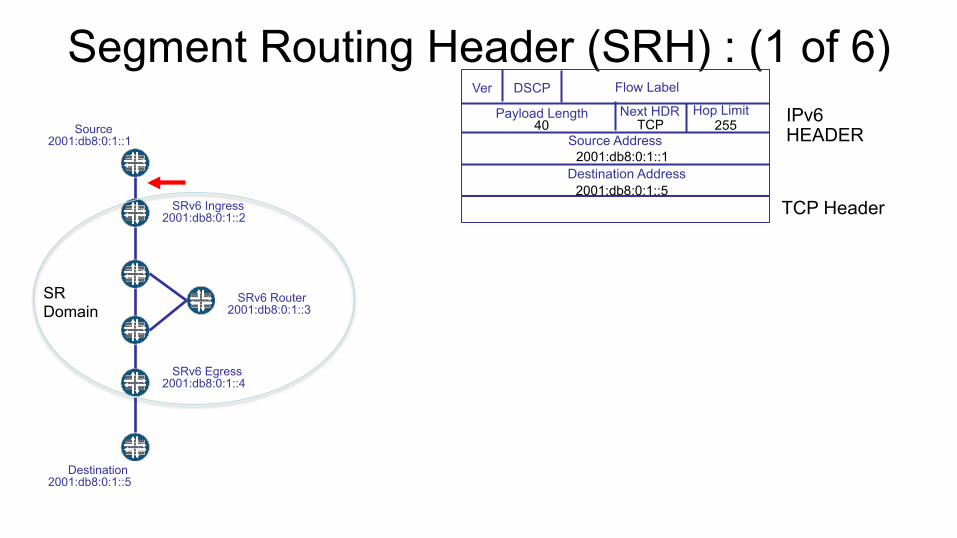
Segment Routing Header (SRH) : (1 of 6) Source 2001:db8:0:1::1
SRv6 Ingress 2001:db8:0:1::2
SRv6 Egress 2001:db8:0:1::4
SRv6 Router 2001:db8:0:1::3
Destination 2001:db8:0:1::5
255
Destination Address
Source Address
Hop Limit Next HDR Payload Length
DSCP Flow Label Ver
IPv6 HEADER
TCP Header
40
2001:db8:0:1::5
2001:db8:0:1::1
TCP
SR Domain

Source 2001:db8:0:1::1
SRv6 Ingress 2001:db8:0:1::2
SRv6 Egress 2001:db8:0:1::4
SRv6 Router 2001:db8:0:1::3
Destination 2001:db8:0:1::5
255
Destination Address
Source Address
Hop Limit Next HDR Payload Length
DSCP Flow Label Ver
IPv6 HEADER
Segment Routing Extension Header
Payload (TCP/IPv6)
HDR Type 56
Length TCP
Next HDR 4
Seg Left
Flags Last Entry
Segment 0
Tag
Segment 1
Segment 2
2001:db8:0:1::4
2001:db8:0:1::3
2001:db8:0:1::2
136
2001:db8:0:1::3
SRH
1
2
2001:db8:0:1::2
Source Address 2001:db8:0:1::1
Destination Address 2001:db8:0:1::5
Ver DSCP Flow Label
Payload Length 40
Hop Limit 255
Next HDR TCP
TCP Headed and Payload
SR Domain
Segment Routing Header (SRH) : (2 of 6)
Source 2001:db8:0:1::1
SRv6 Ingress 2001:db8:0:1::2
SRv6 Egress 2001:db8:0:1::4
SRv6 Router 2001:db8:0:1::3
Destination 2001:db8:0:1::5
254
Destination Address
Source Address
Hop Limit Next HDR Payload Length
DSCP Flow Label Ver
IPv6 HEADER
Segment Routing Extension Header
Payload (TCP/IPv6)
HDR Type 56
Length TCP
Next HDR 4
Seg Left
Flags Last Entry
Segment 0
Tag
Segment 1
Segment 2
2001:db8:0:1::4
2001:db8:0:1::3
2001:db8:0:1::2
136
2001:db8:0:1::3
SRH
1
2
2001:db8:0:1::2
Source Address 2001:db8:0:1::1
Destination Address 2001:db8:0:1::5
Ver DSCP Flow Label
Payload Length 40
Hop Limit 255
Next HDR TCP
TCP Headed and Payload
SR Domain
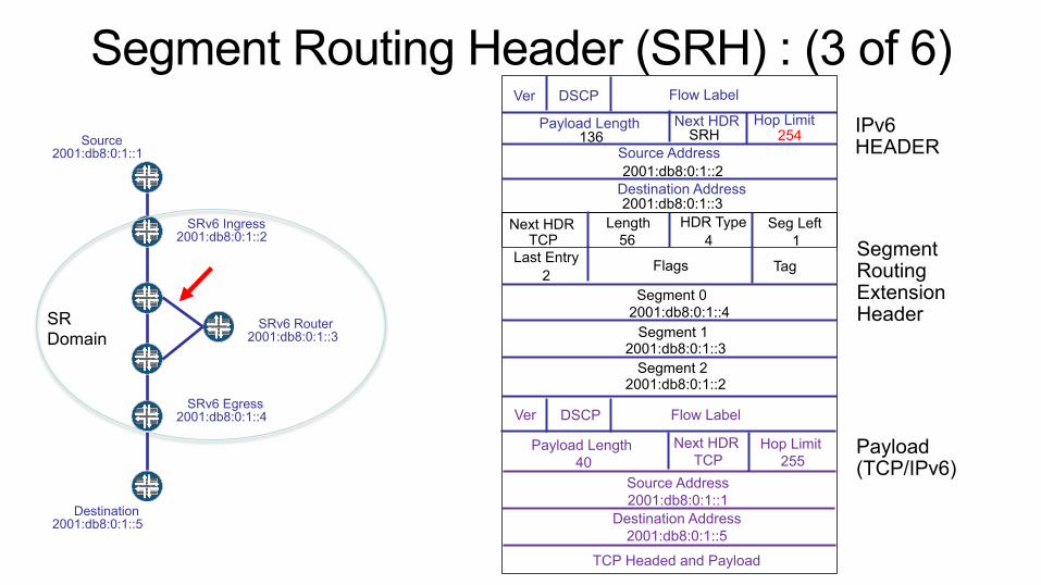
Segment Routing Header (SRH) : (3 of 6)
Source 2001:db8:0:1::1
SRv6 Ingress 2001:db8:0:1::2
SRv6 Egress 2001:db8:0:1::4
SRv6 Router 2001:db8:0:1::3
Destination 2001:db8:0:1::5
253
Destination Address
Source Address
Hop Limit Next HDR Payload Length
DSCP Flow Label Ver
IPv6 HEADER
Segment Routing Extension Header
Payload (TCP/IPv6)
HDR Type 56
Length TCP
Next HDR 4
Seg Left
Flags Last Entry
Segment 0
Tag
Segment 1
Segment 2
2001:db8:0:1::4
2001:db8:0:1::3
2001:db8:0:1::2
136
2001:db8:0:1::4
SRH
0
2
2001:db8:0:1::2
Source Address 2001:db8:0:1::1
Destination Address 2001:db8:0:1::5
Ver DSCP Flow Label
Payload Length 40
Hop Limit 255
Next HDR TCP
TCP Headed and Payload
SR Domain
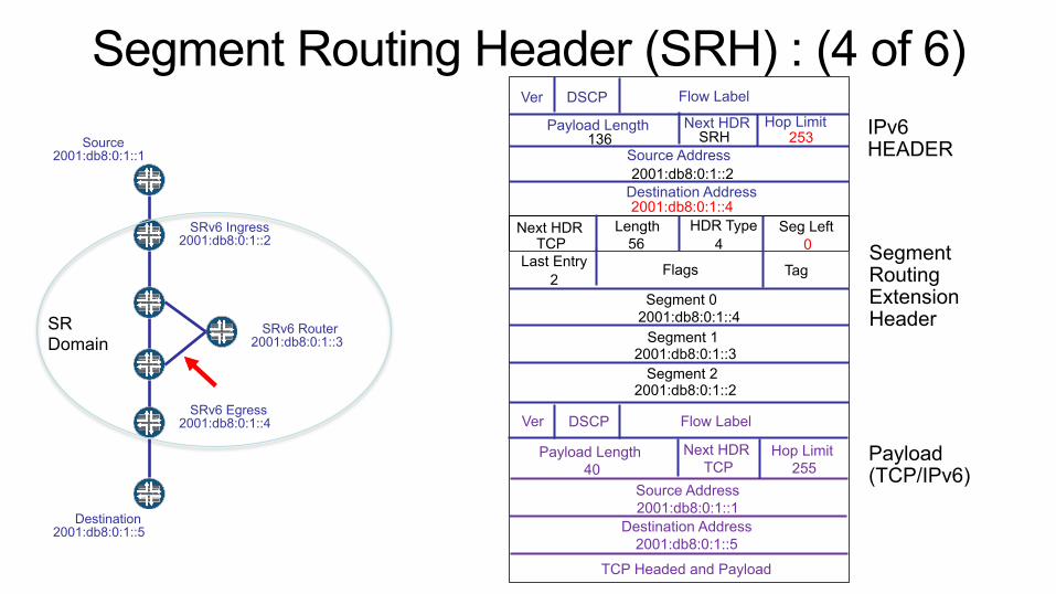
Segment Routing Header (SRH) : (4 of 6)

Source 2001:db8:0:1::1
SRv6 Ingress 2001:db8:0:1::2
SRv6 Egress 2001:db8:0:1::4
SRv6 Router 2001:db8:0:1::3
Destination 2001:db8:0:1::5
252
Destination Address
Source Address
Hop Limit Next HDR Payload Length
DSCP Flow Label Ver
IPv6 HEADER
Segment Routing Extension Header
Payload (TCP/IPv6)
HDR Type 56
Length TCP
Next HDR 4
Seg Left
Flags Last Entry
Segment 0
Tag
Segment 1
Segment 2
2001:db8:0:1::4
2001:db8:0:1::3
2001:db8:0:1::2
136
2001:db8:0:1::4
SRH
0
2
2001:db8:0:1::2
Source Address 2001:db8:0:1::1
Destination Address 2001:db8:0:1::5
Ver DSCP Flow Label
Payload Length 40
Hop Limit 255
Next HDR TCP
TCP Headed and Payload
SR Domain
Segment Routing Header (SRH) : (5 of 6)
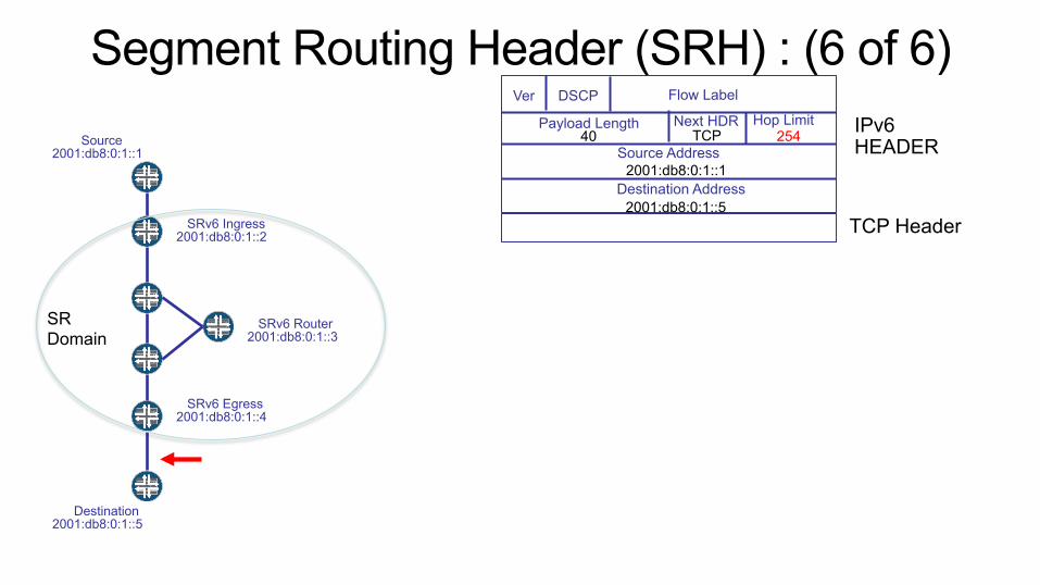
Source 2001:db8:0:1::1
SRv6 Ingress 2001:db8:0:1::2
SRv6 Egress 2001:db8:0:1::4
SRv6 Router 2001:db8:0:1::3
Destination 2001:db8:0:1::5
254
Destination Address
Source Address
Hop Limit Next HDR Payload Length
DSCP Flow Label Ver
IPv6 HEADER
TCP Header
40
2001:db8:0:1::5
2001:db8:0:1::1
TCP
SR Domain
Segment Routing Header (SRH) : (6 of 6)

ADVANCED TYPES OF SID
29

Multiple Points of Presence • An Anycast SID identifies a set of nodes via a non-unique prefix • Choice is made as an IGP shortest path first • May use ECMP • Helps survive failures and allows load ballancing • Set of nodes are usually geographically close
Final segment to destination
First segment to any of three nodes
Second segment to any of three nodes

Identifying SR Paths or Tunnels • Binding SIDs are SIDs that are bound to (i.e., identify) other SR paths or
tunnels • This allows an SR path to include another SR path or a tunnel by reference • If the Binding SID identifies another SR path then the SR forwarding operation
is: – Step beyond the Binding SID (decrement “Segments Left” or pop label) – Insert additional labels for the identified SR path
• If the Binding SID identifies a tunnel then the forwarding operation is: – Step beyond the Binding SID (decrement “Segments Left” or pop label) – Encapsulate the packet and send it down the tunnel
• Useful for scaling the SID stack at the packet ingress • Useful for traversing legacy networks

SR CONTROL PLANE

Path Computation • Performed on SR ingress router or on central
controller • Trivial computations
– Single segment – Multiple statically configured segments
• Non-trivial computations – Constraint-based Shortest Path First (CSPF)
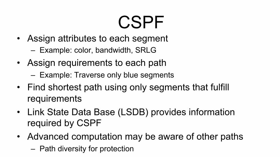
CSPF • Assign attributes to each segment
– Example: color, bandwidth, SRLG
• Assign requirements to each path – Example: Traverse only blue segments
• Find shortest path using only segments that fulfill requirements
• Link State Data Base (LSDB) provides information required by CSPF
• Advanced computation may be aware of other paths – Path diversity for protection
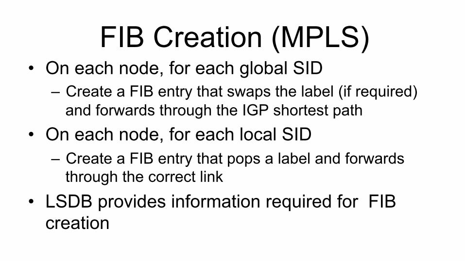
FIB Creation (MPLS) • On each node, for each global SID
– Create a FIB entry that swaps the label (if required) and forwards through the IGP shortest path
• On each node, for each local SID – Create a FIB entry that pops a label and forwards
through the correct link • LSDB provides information required for FIB
creation

SR IGPs • LSDB provides information required for CSPF
computation • LSDB provides information required to create SR
FIB entries • ISIS and OSPF have been enhanced to flood
SR information throughout the IGP domain • SR requires an IGP and little else!

SR Convergence After Failures • Failure occurs between segment endpoints
– For a prefix segment, the SR path restores as quickly as IGP converges
– TI-LFA may decrease IGP restoration time
• Failure occurs at segment endpoint – Head-end restoration strategies available – FRR solutions under consideration
• Anycast SIDs offer failure mitigation

THE CENTRAL CONTROLLER

Benefits • Central control has global view of reserved
bandwidth – Not available at any other point in the network
• Facilitates analytics driven policy – Controller receives telemetry – Based on telemetry, controller alters policy

Risk
• Concentrated point of failure / congestion • Potential performance bottle neck • Risks mitigated by redundant controllers
– May require some form of synchronization

Controller Protocol Options • Controller acquires LSDB
– Controller participates (passively) in IGP – BGP-LS exports LSDB to controller
• Controller sends segment list to ingress router – PCEP – BGP
• Controller imposes policy at ingress router – What traffic to place on a SR path – Flowspec additions to PCEP or BGP

CONCLUSION

Conclusion
• SR moves state from the network to the packet – Simplifies protocols
• Some problems remain to be addressed – OAM, Fast Reroute
• Operational experience required

Q & A


