57
A Short Guide on ARM Exploitation Gaurav Kumar (@grvrajora) Aditya Gupta (@adi1391)
A Short Guide on ARM Exploitation
Gaurav Kumar (@grvrajora) Aditya Gupta (@adi1391)

Contents 1. Introduction
a. Introduction to ARM Processors b. ARM Trustzone c. ARM vs x86
2. Architecture
a. Modes of Operation b. Registers c. Types of registers and their roles d. ARM Status Registers e. Functional Diagram of ARM
3. ARM assembly language
a. Data Processing Instructions b. Arithmetic Instructions c. Logical instructions d. Comparison Instructions e. Memory Access Instructions f. Conditional Execution g. Branch Instructions
4. ARM Exploitation
a. Setting up the lab b. Format string Vulnerability c. Buffer overflows d. Ret to Libc e. Problems in Ret2Libc on ARM f. Ret2ZP and finding new vectors g. ROP (Return Oriented Programming)
5. Conclusion and Bibliography

INTRODUCTION TO ARM ARCHITECTURE
ARM or Advanced RISC Machine is a family of Reduced Instruction Set Computer (RISC) computer processors. According to Wikipedia, It is also the most widely used 32-bit instruction set architecture. Earlier known as Acorn RISC Machines, it is designed and licensed by ARM Holdings, a British company. ARM does not manufacture its own devices, rather sells its licenses to other manufactures, to develop and modify their ARM processor as they wish. Some of the major players include Qualcomm, Samsung, Apple, NVidia, Texas Instruments, Nintendo, Cirrus Logic, and IBM etc. For a list of the ARM processor cores and handsets built on them, have a look at the link http://en.wikipedia.org/wiki/List_of_applications_of_ARM_cores. It gives much better performance than its counterparts, both in terms of efficiency, heat and energy consumption, particularly on embedded devices and smartphones. ARM comes with a toolkit, which includes an emulator, assembler, C and C++ compilers, linkers and a symbolic debugger. ARM architecture is derived from the old Berkeley RISC, some of whose features could be seen in ARM today as well, such as a load-store architecture, fixed length 32-bit instructions and 3-address instruction formats. With the development of more recent Cortex-A and Cortex-A50 series, the performance has taken a leap to an entirely different level. One of the examples could see in the latest iPhone 5, which uses A6 processors. Also,

ARM processors are being in almost all popular smartphones including iOS, Android, Windows Phone and Blackberry OS. It is also the processor used for Samsung Chromebook, and some other Linux distributions. As a result, ARM processors could be seen today everywhere, be it smartphones, TVs, EBook Readers and many more embedded devices.
ARM TrustZone
Mobile and other devices running ARM has been the new favorite target
for attackers. The attacks may include malwares, rootkits, trojans and other
infections, which may steal the private information stored in the device.
To combat device, ARM came up with TrustZone, to enable an open yet
secure environment for the users. ARM processors supporting TrustZone
currently include:
i. ARM Cortex-A15
ii. ARM Cortex-A9
iii. ARM Cortex-A8
iv. ARM Cortex-A7
v. ARM Cortex-A5
vi. ARM 1176
The basis of TrustZone is to partition all the SoC’s hardware and software
into two zones: Secure World and Normal World.

Here’s a list of the architecture and the family of processors based:
Architecture Family
ARMv1 ARM1
ARMv2 ARM2, ARM3
ARMv3 ARM6, ARM7
ARMv4 StrongARM, ARM7TDMI, ARM9TDMI
ARMV5 ARM7EJ, ARM9E, ARM10E, XScale
ARMv6 ARM11, ARM Cortex-M
ARMv7 ARM Cortex-A, ARM Cortex-M, ARM Cortex-R
ARMv8 ARM Cortex-A50
ARM also supports NX (No Execute) protection, which we’ll be discussing later on in this paper.

ARM vs. x86
ARM and x86 instruction set architecture differ from each other in a lot
many ways. ARM is much simpler architecture compared to that of x86,
but ensures that it delivers great performance on Embedded systems.
Another notable difference is in the terms of licensing; Intel’s x86
processors can be made and modified solely by Intel, whereas ARM gives
its licenses to other companies (for a nominal fee), to enable development.
We will be discussing more in-depth of x86 vs. ARM exploitation in the
coming sections.
Modes of operation:
ARM supports seven modes of operation:
1. User mode (us): It is the normal ARM program execution state, and is used for executing most application programs
2. Fast interrupt mode (FIQ): It is used for handling fast interrupts
3. Supervisor mode (svc): It is a protected mode for the operating system
4. Abort mode (abt): It is entered after a data or instruction prefetch abort
5. Interrupt mode (IRQ): It is used for general-purpose interrupt handling
6. System mode (sys): It is the privileged user mode for the operating system
7. Undefined mode (und): It is entered when an undefined instruction exception occurs i.e. an undefined instruction is executed.

Of the entire modes user mode (usr) is the only non-privileged mode while all the others are collectively the privileged mode of the ARM architecture.
Privileged modes are used to service interrupts or exceptions, or to access protected resources.
System mode (sys) can be entered from another privileged mode by modifying the mode bit of the Current Program Status Register (CPSR).
On generation of the exception, the processor switches to the privileged
mode, the current value of the PC+4 is saved into the Link register (R14)
of the privileged mode and the current value of CPSR are saved into the
privileged mode’s SPSR. The IRQ interrupts are also disabled and if the
FIQ mode is entered, the FIQ interrupts are also disabled finally the
Program Counter is forced to the exception vector address and processing
of the exception can start. Usually the first action of the exception routine
will be to push some or the entire user registers onto the stack.
The register organization in different modes is given below
MODE R0 R1 R2 R3 R4 R5 R6 R7 R8 R9 R10 R11 R12 R13 R14 R15
usr R0 R1 R2 R3 R4 R5 R6 R7 R8 R9 R10 R11 R12 R13 R14 R15
fiq R0 R1 R2 R3 R4 R5 R6 R7 R8FIQ R9FIQ R10FIQ
R11FIQ
R12FIQ
R13FIQ
R14FIQ R15FIQ
svc R0 R1 R2 R3 R4 R5 R6 R7 R8 R9 R10 R11 R12 R13SVC
R14SVC R15SVC
abt R0 R1 R2 R3 R4 R5 R6 R7 R8 R9 R10 R11 R12 R13ABT
R14ABT R15ABT
irq R0 R1 R2 R3 R4 R5 R6 R7 R8 R9 R10 R11 R12 R13IRQ
R14IRQ R15IRQ
und R0 R1 R2 R3 R4 R5 R6 R7 R8 R9 R10 R11 R12 R13UND
R14UND R15UND

MODE usr Fiq svc abt irq und CPSR CPSR CPSR CPSR CPSR CPSR SPSR_fiq SPSR_svc SPSR_abt SPSR_irq SPSR_und
REGISTERS
The main purpose of registers is to speed up the whole execution and
store the temporary small values during the execution of a process.
In total ARM has got 37 registers in all out of which 31 are the normal
registers, from which only 16 are accessible or visible at any one time rest
are used for speeding up the execution process. Apart from the normal
registers there are 6 others, which are the status registers. Some of the
registers are only used in certain modes only.
All the registers in Arm are 32 bit registers.
TYPES OF REGISTERS AND THEIR ROLES
Visible or accessible registers: 16 nos. in total
General purpose:
R0 R1 R2 R3 R4 R5 R6 R7 R8 R9 R10
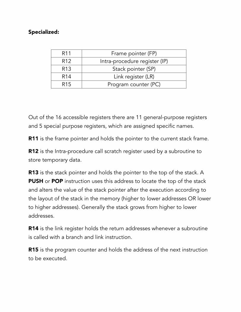
Specialized:
R11 Frame pointer (FP) R12 Intra-procedure register (IP) R13 Stack pointer (SP) R14 Link register (LR) R15 Program counter (PC)
Out of the 16 accessible registers there are 11 general-purpose registers
and 5 special purpose registers, which are assigned specific names.
R11 is the frame pointer and holds the pointer to the current stack frame.
R12 is the Intra-procedure call scratch register used by a subroutine to
store temporary data.
R13 is the stack pointer and holds the pointer to the top of the stack. A
PUSH or POP instruction uses this address to locate the top of the stack
and alters the value of the stack pointer after the execution according to
the layout of the stack in the memory (higher to lower addresses OR lower
to higher addresses). Generally the stack grows from higher to lower
addresses.
R14 is the link register holds the return addresses whenever a subroutine
is called with a branch and link instruction.
R15 is the program counter and holds the address of the next instruction
to be executed.

Apart from the above mentioned special purpose registers, the arguments
of a function are stored in registers r0 to r3. If the number of arguments is
greater than 3 then the excess arguments are stored onto the stack.
ARM STATUS REGISTERS
The status of the currently operating process in ARM is stored in the
CPSR (Current Program Status Register)
Operating processor status is in the Current Program Status Register (CPSR). The CPSR holds: 1. Four condition code flags N, Z, C, V (Negative, Zero, Carry and overflow). 2. One sticky (Q) flag (ARMv5 and above only). This encodes whether saturation has occurred in saturated arithmetic instructions, or signed overflow in some specific multiply accumulate instructions. 3. Four GE (Greater than or Equal) flags (ARMv6 and above only). These encode the following Conditions separately for each operation in parallel instructions:
• Whether the results of signed operations were non-negative • Whether unsigned operations produce a carry or a borrow.
4. Two interrupt disable bits, one for each type of interrupt (two in ARMv5 and below). 5. One (A) bit imprecise abort mask (from ARMv6)

6. Five bits that encode the current processor mode. 7. Two bits that encode whether ARM instructions, Thumb instructions, or Jazelle opcodes are being executed. 8. One bit that controls the endianness of load and store operations (ARMv6 and above only). Each exception mode also has a Saved Program Status Register (SPSR), which holds the CPSR of the task immediately before the exception occurred. The CPSR and the SPSRs are accessed with special instructions. The CPSR layout is as given below:
31 …. 28 27 … 24 23 19 16 15 10 9 8 7 6 5 4 3 2 1 0 N S C V Q de J GE [3:0] IT cond_abc E A I F T mode
Condition code flags: N = Set if a negative result from ALU Z = Set if a zero result from ALU C = Set if a carry is there from ALU operation V = Set if a ALU operation in oVerflowed Q = Set if a saturation has occurred J = Set if the processor is in jazelle state Interrupt disable bits: I = 1 : Disables IRQ F= 1 : Disables FIQ T = Set if the processor in Thumb state T = 0 if processor in ARM state

Mode bits specify the mode of the processor New Bits in V6: GE[3:0] : Used by some SIMD instructions E : controls the endianness of the load/store A : disables imprecise data aborts IT [abcde] for encoding the number of instructions to be conditionally executed in thumb2 instruction groups The functional diagram of ARM:
mCLK
nWAIT
nRESET
nIRQ
nFIQ
ALE
DBE
VDD
VSS
nM[4:0]
A[31:0]
DATA[31:0]
DOUT[31:0]
nMREQ
nENOUT
SEQ
nRW
ABORT
nOPC
nCPI
CPA
CPB
ARM

mCLK : All the memory timing is defined by MCLK, long access
time can be accommodated by stretching this clock
nWAIT : The nWAIT input allows the timing of bus cycles to be extended in increments of complete MCLK cycles, when nWAIT is HIGH on the rising edge of MCLK, a bus cycle completes, when nWAIT is sampled LOW, the bus cycle is extended by stretching the low phase of the internal clock. nWAIT must only change during the LOW phase of MCLK.
nRESET : It is one of the reset signals of ARM.
nIRQ : Non-secure interrupt sources are routed to the nIRQ input.
nFIQ : Secure interrupt sources are routed to the nFIQ input.
ALE (Address Latch Enable) : This signal is used to enable the
address latch.
The VDD and VSS pins are to provide power inputs
nENOUT (Not Enable Output) : It is HIGH for input mode and LOW
for output mode.
DBE (Data Bus Enable) : For enabling the bus to carry data.
nMREQ (No Memory Request) : nMREQ is disserted (to '1') preceding an Internal or coprocessor cycle.
SEQ : Is set to 1 or high when a sequential address fetch is performed using the value of pc.
nRW ( No Read Write) : Indicates the direction of the transfer. Indicates write cycle when HIGH and read cycle when LOW.

nOPC (No Op-code Fetch) : A LOW signal indicates that the current data fetched is an opcode.
nCPI (Not Coprocessor instruction) : To indicate whether the current instruction is for the coprocessor or not.
CPA (Coprocessor Absent) : To indicate whether there is a coprocessor or not.
CPB (Coprocessor Busy) : To indicate whether the coprocessor is busy or in an idle state.
ARM ASSEMBLY LANGUAGE
The ARM opcodes are of 32-bit size and are word aligned i.e. their
addresses are divisible by 4 e.g. 0xbeff2cda4, 0xbeff2cda0 etc.
The Program counter bits [1:0] , are always zero since ARM
instructions are always word aligned. However in case of other
instruction sets such as Thumb the instructions are half word aligned.
Data Processing Instructions:
The data processing instructions can be subdivided into certain
categories:
1. Arithmetic instructions
2. Logical instructions
3. Comparison instructions
4. SIMD (Single Instructions Multiple Data) instructions

Arithmetic instructions:
These perform an arithmetic operation on up to two source operands, and write the result to a destination register. They can also optionally update the condition code flags, based on the result. Of the two source operands one is always a register while the other can have two basic forms, it can be an immediate value or a register value or a shifted register value. If the operand is a shifted register then the shift amount can be either an immediate value or the value of another register The general arithmetic operations include addition (ADD), subtraction (SUB), reverse subtraction (RSB), Add with carry (ADC), subtract with carry (SBC), reverse subtract with carry (RSC). Syntax:
Op{cond}{s} Rd, Rs, Operand2 Where Op is one of ADD, SUB, RSB, ADC, SBC, or RSC. cond is optional conditional code
s is the optional suffix, if s specified the condition code flags are updated on the result of the operation Rd is the destination register i.e. the register for the result Rs is the register holding first operand Operand2 is a flexible second operand Examples: A few examples for better understanding are given below: ADD r1,r2,r3 is equivalent to r1=r2+r3

ADDs r1,r2, #120 is equivalent to r1=r2+120 with the condition flags set according to result
RSB r5,r5,#120 ; subtracts contents of r5 from 120 Logical instructions:
General logical operations include the AND, ORR, EOR and BIC which perform bitwise AND, Exclusive OR and OR operation on the value in Rs and operand2. The BIC instruction is used for bit clearing purpose and performs an AND operation on the bits in Rs with the complements of the corresponding bits in the operand2. Syntax: Op{cond}{s} Rd, Rs, operand2 Where, Op is one of the ADD, EOR, ORR or BIC instruction Cond is the optional condition code S is the optional suffix if s is specified; the condition code flags are updated on the result of the operation. Rd is the register for the result or the destination register. Rs is the register holding the first operand Operand2 is the flexible second operand. Example:

AND r3, r2, #0xabcdef00, is equivalent to r3= r2 AND 0xabcdef00 Comparison instructions It includes two instructions compare (CMP) and compare negative (CMN) The instructions compare the value in a register with operand2. They update the condition flags on the result, but do not update the result in any register. Syntax: op{cond} Rs, operand2 where op is any instruction from CMP or CMN cond is an optional condition code Rs is the register holding the first operand Operand2 is the flexible second operand. The CMP instruction subtracts the value of operand2 from the value in Rs and alters the condition flags accordingly with the result discarded i.e. not stored in any register. The CMN instruction adds the value of operand2 to the value in Rs and alters the condition flags accordingly with the result discarded.

These instruction updates the N, Z, C and V flags according to the results. Example: CMP r1,r2; CMN r1, #120;
SIMD (Single Instructions Multiple Data) instructions:
The SIMD instructions operate on multiple 16 bit or 8 bit values
packed into standard 32-bit general purpose registers. This permits
certain operations to execute quickly without implementing
additional computation units. The mnemonics for having 8 or 16
appended to the base form, indicating the size of data values,
recognizes these instructions operated on. Example UADD8
r0,r1,r2 ; This operation performs a parallel addition of four lanes of
8-bit elements packed into vectors stored in general purpose
registers r1 and r2, and places the result into a vector in register r0.
Memory access instructions:
1. LDR and STR, words and unsigned bytes
Both LDR and STR can have four possible forms:
Zero offset : The value of Rs is used as an address for the transfer.
Syntax: op{cond}{B}{T} Rd , [Rs]
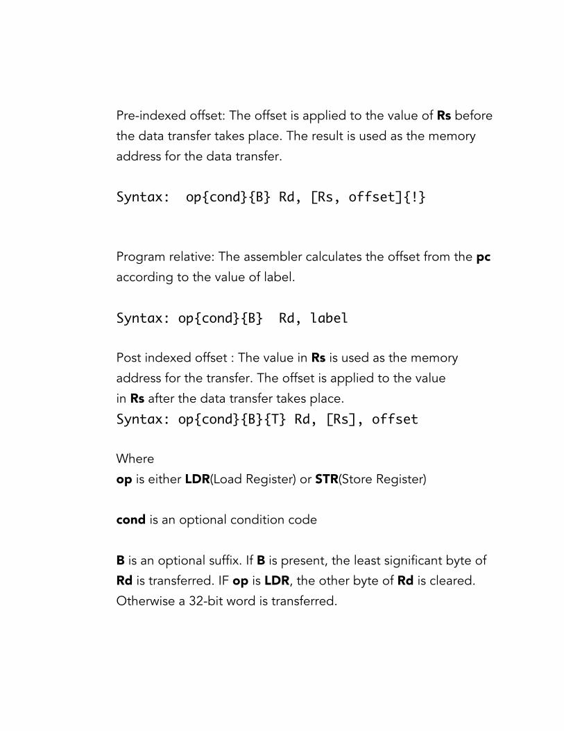
Pre-indexed offset: The offset is applied to the value of Rs before
the data transfer takes place. The result is used as the memory
address for the data transfer.
Syntax: op{cond}{B} Rd, [Rs, offset]{!}
Program relative: The assembler calculates the offset from the pc
according to the value of label.
Syntax: op{cond}{B} Rd, label
Post indexed offset : The value in Rs is used as the memory
address for the transfer. The offset is applied to the value
in Rs after the data transfer takes place.
Syntax: op{cond}{B}{T} Rd, [Rs], offset
Where
op is either LDR(Load Register) or STR(Store Register)
cond is an optional condition code
B is an optional suffix. If B is present, the least significant byte of
Rd is transferred. IF op is LDR, the other byte of Rd is cleared.
Otherwise a 32-bit word is transferred.
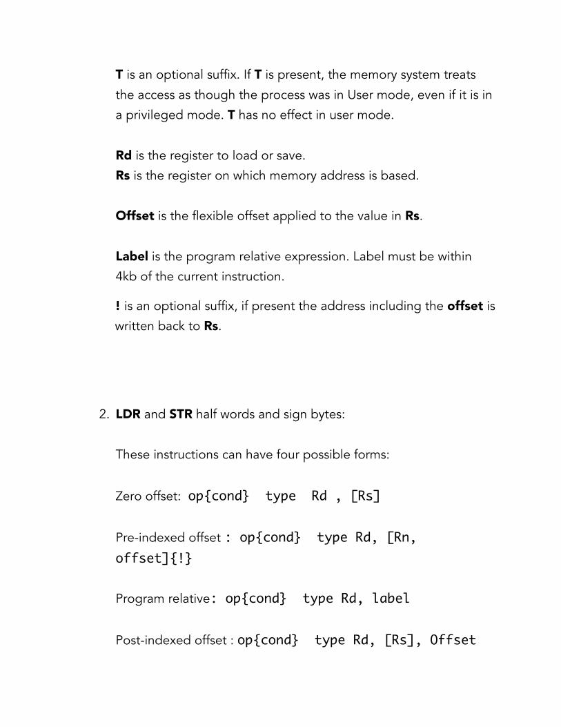
T is an optional suffix. If T is present, the memory system treats
the access as though the process was in User mode, even if it is in
a privileged mode. T has no effect in user mode.
Rd is the register to load or save.
Rs is the register on which memory address is based.
Offset is the flexible offset applied to the value in Rs.
Label is the program relative expression. Label must be within
4kb of the current instruction.
! is an optional suffix, if present the address including the offset is
written back to Rs.
2. LDR and STR half words and sign bytes:
These instructions can have four possible forms:
Zero offset: op{cond} type Rd , [Rs]
Pre-indexed offset : op{cond} type Rd, [Rn, offset]{!}
Program relative: op{cond} type Rd, label
Post-indexed offset : op{cond} type Rd, [Rs], Offset
Here in the above syntaxes we only have one new attribute i.e.
type
Type must be one of:
SH for signed half word (for LDR only)
H for unsigned half word
SB for signed byte (for LDR only)
Label is the program relative expression. Label must be within
255 bytes of the current instruction.
Offset syntax:
Both pre-indexed and post-indexed syntaxes can be either of the
following:
#expr {-} Rs Where:
- Is the optional minus sign. If – is present the offset is
subtracted from Rs. Otherwise the offset is added to Rs.
Expr is an expression evaluating to an integer in the range -255
and +255.
Rs is the register containing the value to be used as the offset.

3. LDR and STR, halfwords:
Load two consecutive registers and store two consecutive
registers
These instructions can have four possible forms:
Zero offset: op{cond}D Rd , [Rs]
Pre-indexed offset : op{cond}D Rd, [Rn, offset]{!}
Program relative : op{cond}D Rd, label
Post-indexed offset : op{cond}D Rd, [Rs], Offset
Here:
Rd is one of the registers to load or store. The other one is
R(d+1). Rd must be even numbered register and not R14.
Rs is the register in which memory address is based. Rs must not
be the same as Rd or R(d+1) unless the instruction is either zero
offset or pre-indexed without write back.
Label is a program relative expression evaluating to a numeric
value between -252 and +252
4. LDM and STM
Load and store multiple registers. Any combination of registers
R0 to R15 can be transferred.

Syntax: op{cond}mode Rs{!}, reglist{^}
Where:
Op is either LDM or STM
Cond is an optional conditional code.
Mode is any one of the following:
IA increment address after each transfer.
IB increment address before each transfer.
DA decrement address after each transfer
DB decrement address before each transfer.
FD full descending stack
ED empty descending stack
FA full ascending stack
EA empty descending stack
Rs is the base register containing the initial address for the
transfer. Rs must not be R15.
Reglist is the list of registers to be loaded or stored, enclosed in
braces. It can also contain register ranges.
^ is an optional suffix. It must not be used in user mode or system
mode. It has two purposes. If op is LDM and reglist contains the
pc i.e. R15, the SPSR is copied into CPSR. This is for returning
from exception handlers. This is used for only exception modes.
Example:

STMFD r13! , {r0,r1-r3,PC}; Push registers including the
stack pointer
LDMFD r13! , { r0, r1-r3, PC}; Pop the register and
return from a subroutine
Conditional Execution:
An optional condition code can be added to almost every ARM
instruction. An instruction with the condition code (cond) is only
executed if the condition code flags in the CPSR meet the
specified condition. The different condition codes are: Suffix Flags Meaning EQ Z set Equal NE Z clear Not equal CS/HS C set Higher or same (unsigned >=) CC/LO C clear Lower (unsigned <) MI N set Negative PL N clear Positive or zero VS V set Overflow VC V clear No overflow HI C set and Z clear Higher LS C clear or Z set Lower or same GE N and V the same Signed >= LT N and V different Signed < GT Z clear, and N and V the same Signed > LE Z set, or N and V different Signed <= AL Any Always
To make the instruction update the flags you have to include the
S suffix.

ARM Branch instructions:
ARM includes different instruction for branching i.e. to transfer the
control to a subroutine like a call instruction in x86 architecture.
There are different forms of branch instructions available in ARM:
B and BL:
Branch and branch with link
Syntax:
Op{cond} label
Where:
Op is either B or BL
Cond is optional condition code
Label is a program relative expression
The B instruction causes a branch to the label. The BL instruction
copies the address of the next address i.e. the return address into
R14 (LR, Link Register) and then causes the branch to label.
BX:
Branch and optionally exchange instruction set
BX instruction causes a branch to the address in Rs and changes
the mode to Thumb if Bit 0 of Rs is set.

Syntax: BX{cond} , Rs
Here Rs is the register containing the address to branch to.
Bit 0 of Rs is not used as part of address.
If Bit 0 if Rs is set, the instruction sets the T flag in the CPSR , and
the code at the destination is interpreted as thumb code.
If bit 0 of Rs is clear, Bit 1 must not be set
BLX:
Branch with link and optionally exchange instruction set. This
instruction has two alternative forms:
BLX{cond} Rs : A conditional branch with link to an absolute
address held in a register,
BLX label: An unconditional branch with link to a program-
relative address
The BLX cannot branch to an address outside the range of 32Mb
of the current instruction.
Till now we have covered almost all general instruction that are
most often used in ARM assembly language.
For more reference to ARM instructions you can visit:
http://infocenter.arm.com/

SETTING UP THE PENTEST LAB
To perform all the exercises in the upcoming sections on the ARM platform, you could either set up a virtual environment on your system based on ARM architecture, or you could buy ARM based devices such as RasberryPi, BeagleBoard, Pandaboard, ARMini, Cubox. In this section, we will discuss about how to set up a virtual lab environment for ARM based exploitation. The first thing needed to set up the environment is to download Qemu . Qemu is a fast processor emulator, which supports ARM, PowerPC, sparc and even x86 emulation. Qemu has two operational modes: User Mode Emulation: To launch individual applications, made for one
OS, to run on another OS architecture
Full System Emulation: To emulate an entirely different OS architecture on another OS architecture. This will be our targeted lab environment, to give us full control of the system, including the applications, debugging and testing.
You can download Qemu from its official website - http://wiki.qemu.org/Download Also, make sure that you have all the dependencies installed, before installing Qemu.
After downloading run the configuration script, to build Qemu for ARM. $ ./configure –target-‐list=arm-‐softmm $ make && make install $ qemu-‐img create ubuntu.img 15G Here we have created a hard disk for our Virtual Environment, assigning it a 15 GB of disk space. Here we will be using Ubuntu 10.10 for our test purposes (or any other version of Linux you’re comfortable with) $ qemu -‐hda ubuntu.img -‐cdrom ubuntu-‐10.10-‐desktop-‐i386.iso -‐m 512 -‐boot d In the above command, we are specifying the hard disk for our VM, with the -hda option, which we just now created to be ubuntu.img. -cdrom specifies the CD/DVD or the ISO image we will be using as an image for VM. We will be specifying the RAM for our environment using the -m parameter, in this case to be 512 MB. Finally, we will be instructing Qemu to load our environment with the -‐boot d option. Once installed, you could boot the created virtual environment with the following command. $qemu -‐m 512 -‐hda ubuntu.img Once that we have set up the lab, we could now move ahead to the basics of GDB and exploitation.

A debugger is a program which lets you analyze what is going on inside a user-specified program while it is in the execution phase, or when it crashes. To understand GDB better and its various functionalities, let us first of all analyze a sample program on the ARM architecture. /******Simpleprog.c******/ #include <stdio.h> int main (int argc, char **argv) { printf (“Hello World”); char a; } Compile the above program using GCC. root@debian-‐armel:~# gcc simpleprog.c -‐g -‐o simpleprog -‐g is to load the debugging symbols -‐o is to specify the output object file To debug this file with GDB, type in gdb ./simpleprog You will be greeted with a (gdb) prompt. To get the program code, type in list within GDB. It will show you the underlying code from which the file is compiled.
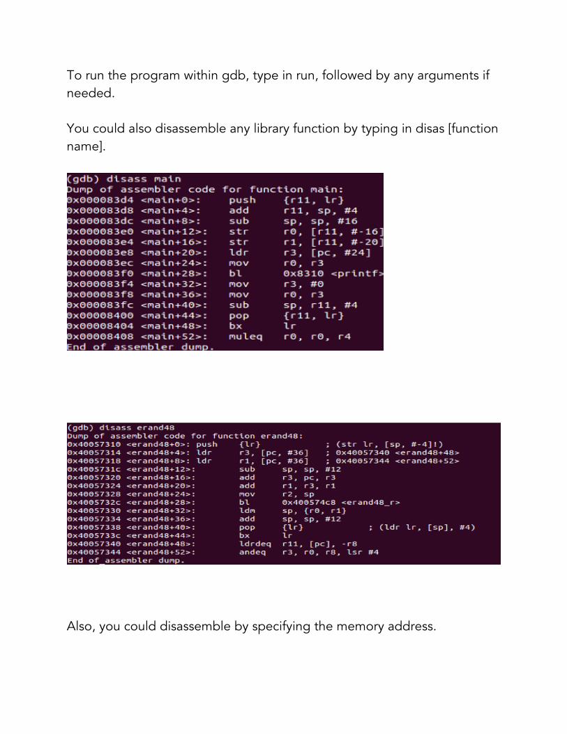
To run the program within gdb, type in run, followed by any arguments if needed. You could also disassemble any library function by typing in disas [function name].
Also, you could disassemble by specifying the memory address.
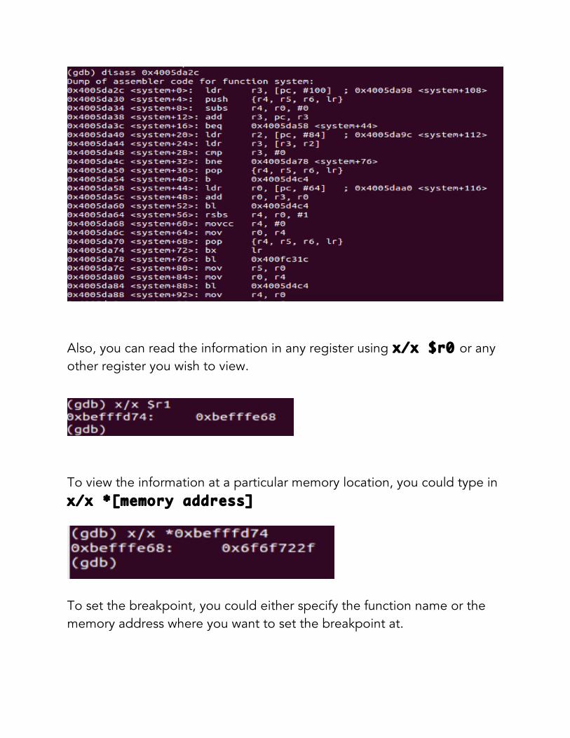
Also, you can read the information in any register using x/x $r0 or any other register you wish to view.
To view the information at a particular memory location, you could type in x/x *[memory address]
To set the breakpoint, you could either specify the function name or the memory address where you want to set the breakpoint at.

To view the current status of all the registers, type in info registers, and it would present you with the list of registers.

To view the stack layout, x/wx $sp Where w is the number of consecutive double words
You could even view the help in GDB by typing in help.

FORMAT STRING VULNERABILITY A format string vulnerability is a kind of vulnerability in certain C functions, that due to unescaped user input, could treat the input as commands, and could lead to arbitrary data write to arbitrary locations, crash the program, execute commands, get root shell and so on. Format string vulnerabilities allows an attacker to dump the stack, and thus place the shell code in a manner, so as after knowing the address, he would be able to execute it. Here we have taken an example of a very simple program as given in the figure below which has format string vulnerability, so we can easily examine the stack by exploiting the vulnerability as shown in the figures below.
Now, as we can see the above program is using a printf function to print argv[1] to the screen. The prototype of the printf function is given below: printf(“format strings “, variable names);

Format strings are the ASCIIZ strings used to specify and control the representation of different variables eg: printf(“%d”, i); In this case the printf function tells that, convert i which is an integer to string and display on the screen. So a format function uses the format string to convert C data types into a string representation. Format strings control the various aspects of execution of format function. They also control the number of variables and representation in output. The input format string decides the number of arguments to be read off the stack. So, in the case of our example if we give our input string as a format string then the printf function can be deceived and be used to read values of the stack as shown below. Our input:
We are using %08x instead of %x so as to get properly formatted output in hexadecimal. Then, as shown below we can see that we are able to examine the whole stack and the data stored on the stack

So using the above technique an attacker can examine the whole stack and steal relevant data such as stack cookies etc. or can see the position of return addresses and replace them with his own and thus can manipulate the flow of the program.

BUFFER OVERFLOW Buffer is a temporary space of memory used to hold data. Buffer overflow generally happens when the data written to the buffer is larger than the size of the buffer, and due to the insufficient bound checking it overflows the buffer and writes to adjacent memory locations, which could be some important data or any return addresses etc. The local variables generally act as buffer variables or buffer. In buffer overflow, our main aim is to somehow modify the return address, and take control of the program flow by controlling the link register (LR). Once we have the control of the return address, we can take the control of the entire program and make it perform our desired actions. Here we have a vulnerable program as given in the figure below having a function named “vulnerable”, which is vulnerable to buffer overflow attack, as it uses strcpy function to copy buff into the local variable buffer which is of size 10 bytes. So, if we input a string of length greater than 10 byes and copy that to buffer, then we can cause a buffer overflow and write to the adjacent memory locations. Our aim here will be to overwrite the return address of the vulnerable function.
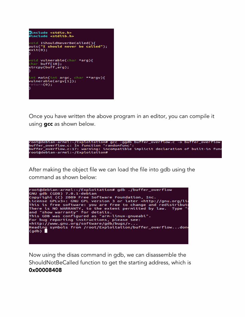
Once you have written the above program in an editor, you can compile it using gcc as shown below.
After making the object file we can load the file into gdb using the command as shown below:
Now using the disas command in gdb, we can disassemble the ShouldNotBeCalled function to get the starting address, which is 0x00008408

We will be using this address to overwrite the return address.
Now, we can also disassemble the main function to see the location of the return address on the stack. Looking at the dissembled code of the main function we can figure out that there is a function call to vulnerable function at the address 0x000084a4 and the return address of this vulnerable function will be the next instruction only i.e. at location 0x000084a8.
Now, we can run the program in gdb using r command and check the layout of the stack and eventually see the locations of the return address and the buffer, which is to be overflown.
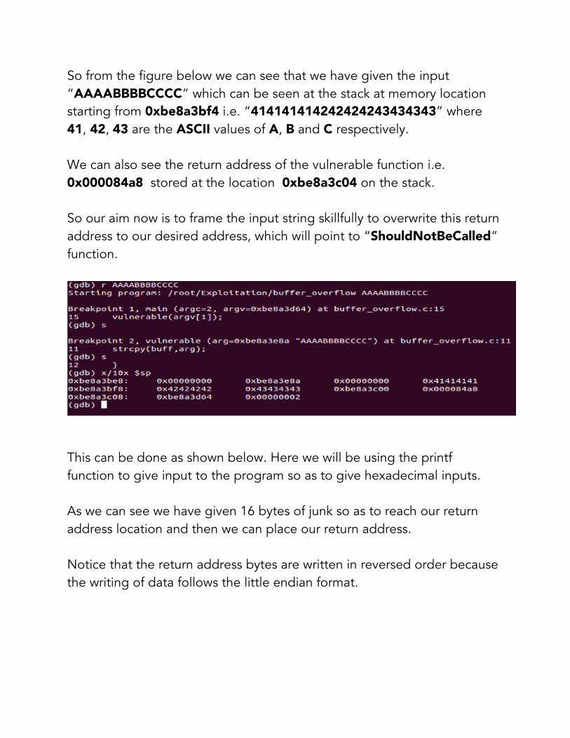
So from the figure below we can see that we have given the input “AAAABBBBCCCC” which can be seen at the stack at memory location starting from 0xbe8a3bf4 i.e. “414141414242424243434343” where 41, 42, 43 are the ASCII values of A, B and C respectively. We can also see the return address of the vulnerable function i.e. 0x000084a8 stored at the location 0xbe8a3c04 on the stack. So our aim now is to frame the input string skillfully to overwrite this return address to our desired address, which will point to “ShouldNotBeCalled” function.
This can be done as shown below. Here we will be using the printf function to give input to the program so as to give hexadecimal inputs. As we can see we have given 16 bytes of junk so as to reach our return address location and then we can place our return address. Notice that the return address bytes are written in reversed order because the writing of data follows the little endian format.

Now if we step through the program we can see that we have reached the “ShouldNotBeCalled” function even though there was no call to that function as shown below.
Return to Libc (Ret2Libc): Ret2Libc i.e. Return to Libc is the technique used to subvert the non executable stack prevention. Libc library is mapped into the memory space of most programs. As we have seen in Buffer Overflows, once we can corrupt the stack we can point the return address to a function in the Libc library. We generally use the system() function in the Libc library which takes “/bin/sh” as the argument in order to get a shell. Why Ret to Libc is not possible on ARM : Ret to Libc is generally not possible on ARM, as in x86 architecture the arguments to a function are passed onto the stack only, while in the case of ARM processors the arguments to the function should be placed in registers, which is a problem as we can only overwrite the stack using the buffer overflow technique and we don’t have any control on the register values. So in order to place the arguments into the registers we need to take a different approach. We have to first return to a memory location, which contains the code to load the registers. Once we have loaded the registers with the required arguments we need to take the control of our program to the desired Libc function which is system() in our case. One of such approach was discussed by ‘Zuk’ which he called Ret2ZP (Return To Zero Prevention) in which he used the code present in the
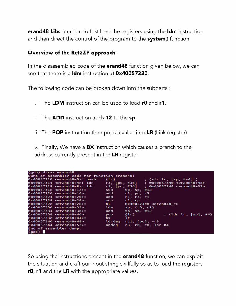
erand48 Libc function to first load the registers using the ldm instruction and then direct the control of the program to the system() function. Overview of the Ret2ZP approach: In the disassembled code of the erand48 function given below, we can see that there is a ldm instruction at 0x40057330. The following code can be broken down into the subparts :
i. The LDM instruction can be used to load r0 and r1. ii. The ADD instruction adds 12 to the sp iii. The POP instruction then pops a value into LR (Link register) iv. Finally, We have a BX instruction which causes a branch to the address currently present in the LR register.
So using the instructions present in the erand48 function, we can exploit the situation and craft our input string skillfully so as to load the registers r0, r1 and the LR with the appropriate values.
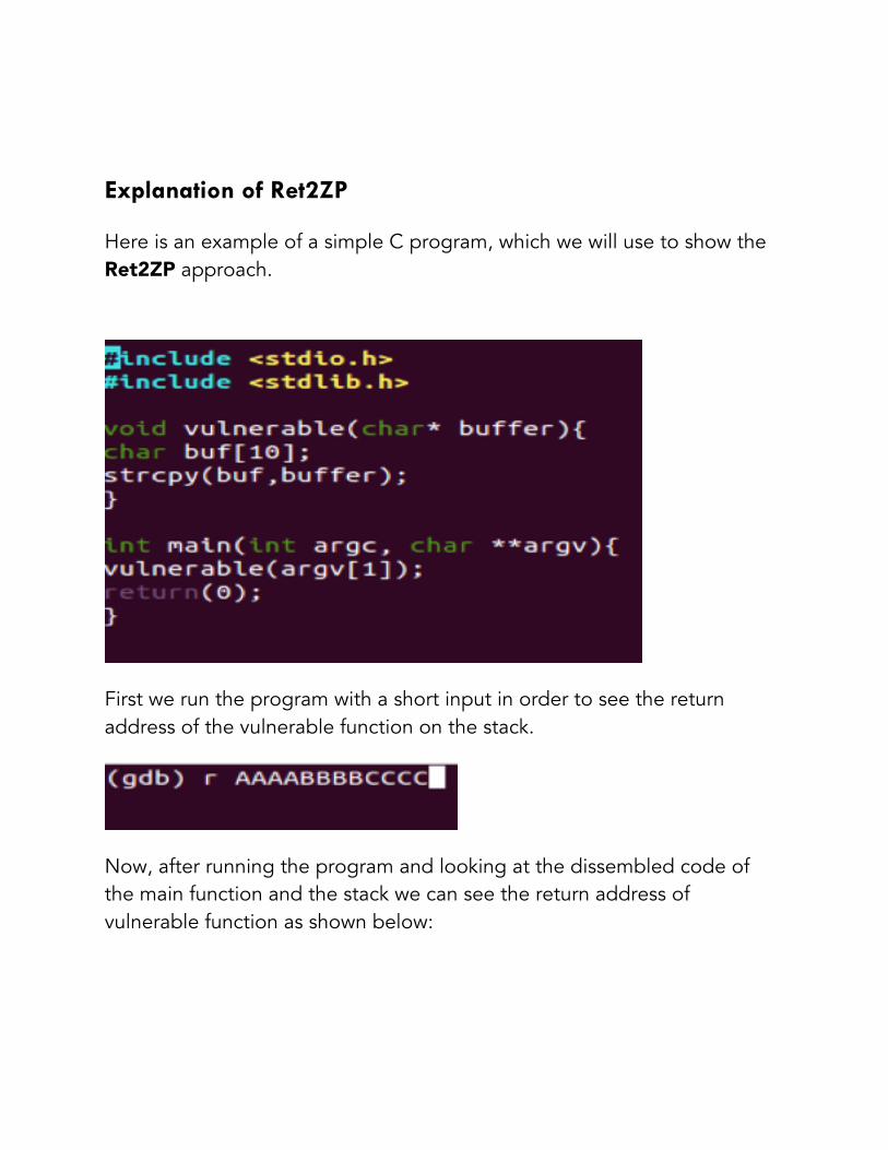
Explanation of Ret2ZP Here is an example of a simple C program, which we will use to show the Ret2ZP approach.
First we run the program with a short input in order to see the return address of the vulnerable function on the stack.
Now, after running the program and looking at the dissembled code of the main function and the stack we can see the return address of vulnerable function as shown below:
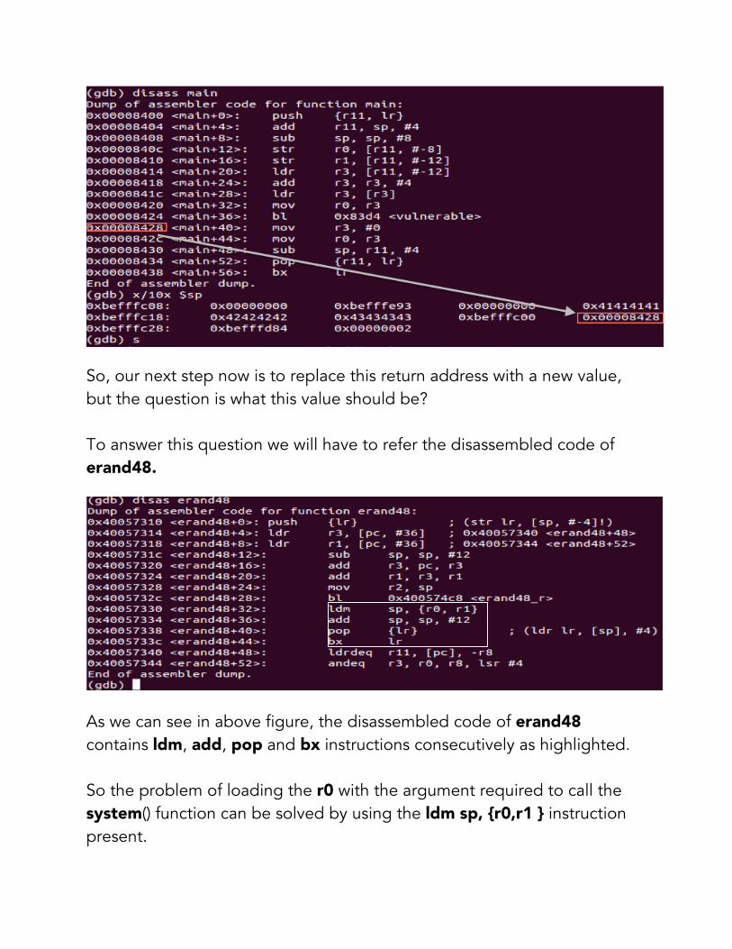
So, our next step now is to replace this return address with a new value, but the question is what this value should be? To answer this question we will have to refer the disassembled code of erand48.
As we can see in above figure, the disassembled code of erand48 contains ldm, add, pop and bx instructions consecutively as highlighted. So the problem of loading the r0 with the argument required to call the system() function can be solved by using the ldm sp, {r0,r1 } instruction present.

So our next step now is to replace the return address with the address of the ldm instruction present in the erand48 Libc function i.e. 0x40057330. Also, We will have to take care of the values that are being loaded into the r0 and r1 by the ldm instruction. This could be controlled by overwriting the stack with appropriate values as the ldm is taking the data from stack only and storing that to R0 and R1. In the same manner, we can also control what is being popped into LR . So, we are first going to replace the return address with the value 0x40057330, then we are going to load the address of “/bin/sh” into R0. We need not to care about what is loaded in R1 as the system() call only needs one argument which will be stored in R0. We would then be popping the address of the system() function 0x4005da2c into LR and the BX LR instruction will cause a branch to the system() function. So, our input string to overflow the buffer and overwrite the different positions on the stack in order to provide appropriate data to load into the registers and LR should be designed as given below.
A B C D E F G H

A: Junk value to reach the return address of the vulnerable function. B: Any valid address present in the context of the program. C: Our return address in the errand48 function i.e. the address of the ldm Instruction D: The address of the “/bin/sh” string placed on the stack which we will be inputting at the end. This value will be loaded into r0. E: Any junk value, which will be loaded into r1. F: Any valid address present in the context of the program. G: The address of the system() function which will be popped into LR H: “/bin/sh”, the argument to the system() function whose address we have earlier in the input string. So, finally our input will look like something as given below: A B C D E F
G H After stepping through the program with the above input we will end up getting a shell as shown below:

FINDING YOUR OWN ATTACK VECTORS Here is another example of exploiting the same situation using a different approach and another Libc function. Here we will be using a code piece present in the seed48 Libc function. We will exploit the same program code, which we had in previous example:
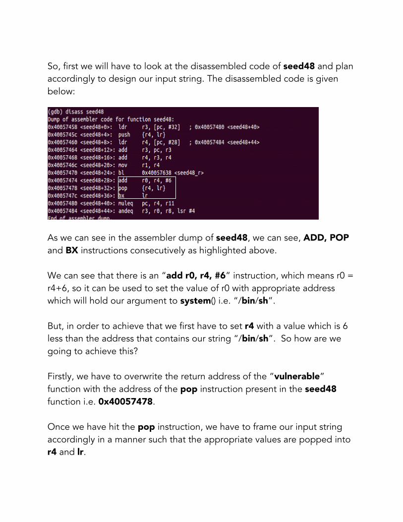
So, first we will have to look at the disassembled code of seed48 and plan accordingly to design our input string. The disassembled code is given below:
As we can see in the assembler dump of seed48, we can see, ADD, POP and BX instructions consecutively as highlighted above. We can see that there is an “add r0, r4, #6” instruction, which means r0 = r4+6, so it can be used to set the value of r0 with appropriate address which will hold our argument to system() i.e. “/bin/sh”. But, in order to achieve that we first have to set r4 with a value which is 6 less than the address that contains our string “/bin/sh”. So how are we going to achieve this? Firstly, we have to overwrite the return address of the “vulnerable” function with the address of the pop instruction present in the seed48 function i.e. 0x40057478. Once we have hit the pop instruction, we have to frame our input string accordingly in a manner such that the appropriate values are popped into r4 and lr.

We have already discussed about the value to be popped in r4, (that is 6 less than the address that contains the string /bin/sh) Now the next instruction we want to hit is the ADD instruction, so the next value in the input string should be the address of the ADD instruction which will be popped in to lr i.e 0x40057474. After setting the r0 using add instruction, the program will then hit the pop instruction. This time we don’t care about what is popped into r4 so it can be any junk value but we have to take care about what is popped into lr which is the address of the system() Libc function. Once we have set the input string accordingly we will have our arguments in the register r0 and can proceed further to make a system call and eventually getting a shell So first we can give some random valid input as we did in the previous example while using erand48 function to examine the stack and see the position of return address and then accordingly design our input string.

So our input string will look as follows:
“AAAABBBBCCCC” is the junk we don’t have to care about 1 : Is some valid memory location in the context of the program. 2: Is the address of the pop instruction in the seed48 function. 3: Is the value to be popped into r4 which is 6 less than the address at which the argument string “/bin/sh” is present. 4: Is the value to be popped into lr to cause a branch to the add instruction i.e 0x40057474 5: Could be any junk value which will be popped into r4 again, after that the control again reaches the pop instruction after executing add. 6 : Is the address of the system() function where we want to branch this time. After that we have our string “/bin/sh” whose address is in r0 currently.

So after framing our input string accordingly we can step through the program and eventually get a shell as shown in the figure below: Note : In both the examples discussed above, one using the function errand48 and the other seed48, you may have to take some care about the address of the “/bin/sh” string on the stack. The problem can be overcome if you closely examine the stack addressing and how the layout of the attack is changing with increasing the length of the input string and don’t forget to turn ASLR off. echo 0 > /proc/sys/kernel/randomize_va_space

ROP (Return Oriented Programming) On ARM : Return Orienting Programming is used for exploitation in order to bypass the code and data separation mechanism, which is used as a protection technique. In this protection technique a certain memory area can either be used to write data to or execute data but not both. In ARM the Execute Never (XN) bit was introduced in the virtual memory system architecture in version 6. The basis on which all ROP exploitation techniques are based is the Ret2Libc. Just like the working of ret2libc exploits, in which the attacker redirects the control flow of the program to other library function in the Libc library with all the data set on the stack and registers which are required by the function to be called, In the same way return oriented programming is performed in which the attacker hijacks the control flow of the program and returns to a location in the Libc and after several jumps completes the tasks which he intends to do. In other words, Ret2libc can be viewed as the simplest ROP. The parts required to build a Return Oriented Program are called gadgets or code chunks. These code chunks can be found in the Libc library functions. A gadget can be any sequence of instructions, which is located in the targeted binary and provides a usable operation. In order to build a program from these gadgets they must be combinable. They are combinable if they end in an instruction that controlled by the user alters the control flow i.e. the last instruction of a gadget must be a

free branch instruction so that the attacker can jump to other gadget using that instruction. So a gadget should be able to perform some operations as well as, be able to branch to other locations at the end. For example as shown below, the highlighted instructions in different colored boxes can be individual gadgets. Instructions in each box can act as an individual gadget because they fulfill both the requirements of doing some operations and having a free branch in the end.

ROP is used for exploitation in very complex situations. A lot of such gadgets are put together to make a gadget chain, which will set the registers appropriately and jump to an appropriate function in Libc in the end. So, the basic approach of ROP can be shown as below:
Using the above shown address we can form a chain of gadgets to finally call a library function or execute our shell code placed on the stack.
Gadget2
Some instructions
Branch to gadget3
Gadget1
Some instructions Branch to gadget2
GadgetN
Some instruction
Branch to gadget(N+1)

CONCLUSION Due to less resources available on ARM Exploitation, it is not much widely practiced. But it is surely one of the most interesting areas to work upon the field of exploitation. We have written this paper trying out different stuffs, and learning from the experiences. We hope that it would provide beneficial to anyone seeking information on ARM Exploitation. We would love to get any kind of feedback or corrections on our paper, if any. You could contact us at the following: Gaurav Kumar : [email protected] @grvrajora Aditya Gupta : [email protected] @adi1391

REFERENCES
ARM Exploitation : http://www.exploit-db.com/wp-content/themes/exploit/docs/14548.pdf
Exploiting ARM Systems by Tiger Security http://www.exploit-db.com/wp-content/themes/exploit/docs/16151.pdf
Return Oriented Programming without Returns : http://www.cs.jhu.edu/~s/papers/noret_ccs2010/noret_ccs2010.pdf
Popping shell on Android Devices by Zuk - http://media.blackhat.com/bh-dc-11/Avraham/BlackHat_DC_2011_Avraham-Popping_Android_Devices-Slides.pdf
Non Executable Stack ARM Exploitation - https://media.blackhat.com/bh-dc-11/Avraham/BlackHat_DC_2011_Avraham_ARM%20Exploitation-wp.2.0.pdf
Alphanumeric RISC ARM Shellcode (Good read, if you’re planning to write shellcodes for ARM) - http://www.phrack.org/issues.html?issue=66&id=12


