infrared active fundamentals are expected. The result of factor group analysis is given in Table I. In these funda- mentals, the NO:~ internal ones are above 700 cm L with no isotopic band shifts. The external ones can be classi- fied into two groups. One group is the Li + translational lattice modes, and the characteristic isotopic frequency shifts are expected for these bands with ratios of about 1..06 for v"Li/v~Li. For the second group, no band shifts are expected for the NO:~ translational and rotational lattice modes. The Raman frequencies observed are listed in Table II. Because the Li ' site of LiNO:~ crystal is located on a center of symmetry, there are no Raman active Li--O modes and none of the seven observed Raman bands shows the isotopic frequency shift. Three internal modes, the NO:~ asymmetric stretching (v:0, symmetric stretch- ing (v,), and in-plane bending (v4), are assigned at 1383, 1069, and 734 cm ', respectively. The band at 1674 cm is considered as the overtone of Raman inactive band v~. v v, of N~"O~'SO - is also observed at 1050 cm-'. ~ Two low frequency bands at 235 and 123 cm ' are, respectively, the NO:~- rotational and translational lattice modes. 7' ~ In the infrared spectra, three internal modes, the NO:z asymmetric stretching (v..0, out-of-plane bending (vD, and in-plane bending (v4), are observed at 1392, 838, and 738 cm-' as listed in Table II. The frequency separations of v:~ and v~ in the Raman and infrared spectra can be explained in terms of the NO:~ • • • Li ÷ . . • NO:C crystal field. Two observed bands at 314 and 275 cm ' for "LiNO:~ and at 300 and 265 cm ' for 7LiNO:~ give the characteristic TABLE I. Factor group analysis for LiNOa." D:~d N T Li + NO3- NO.., " NO:( Activity T' T' R' n a~s 1 0 0 0 0 1 Raman a2g 3 0 0 1 1 1 Inactive eg 4 0 0 1 1 2 Raman a~u 2 0 1 0 0 1 Inactive a2,, 4 1 ~ 1 1 Infrared e~ 6 1 2 1 2 Infrared N, number of degrees of freedom; T, number of overall translations of Bravais cell; T' number of translational lattice modes; R', number of rotational lattice modes; n, number of internal modes. TABLE II. Infrared and Raman frequencies (in cm-l). Infrared Raman "LiNO:~ 7LiNO:, "LiNO:~ 7LiNOa 1794m 1794m 1463 w, sh 1463 w, sh 1392 vs 1392 vs 838 s 838 s 817 w, sh 817 w, sh 771 w 771 w 737 m 738 m 314 s, br 300 s, br 275 s, sh 265 s, sh 168 m 167 m 153 w 152 w wl -t- v4 1674 w 1674 w 2 v~ v4+ v4 v:~ v, NO:~ e, 1383 s 1382 s v:l v,, NO:, ~- eg 1069 vs 1069 vs v, v~ NO:,- a~g 1049 w 1050 w See text v2 oJ,, NO:~- a2~ See text See text v4 & NO:~- e. 734 s 734 s PP4 ~i NO:C % {TT;Li + a2u Li+ eu T' Li+ e~ 235 vs 235 vs R' NO:, eg R' NO3 e~ R' NO:~ a2" 123 m 123 m T' NO3- eg isotopic shifts with frequency ratios of 1.05 and 1.04 which are close to the value expected from G matrix elements. For the NO:( external modes, three bands at 166, 152, and 96 cm -~ were observed for 7LiNO:, in the previous papers, s' :*' ~* However, the result of normal co- ordinate analysis indicates only two bands below 200 cm '." In this study, the band at 96 cm ', which is very close in frequency to one of the water vapor bands, is not found for both "LiNO:~ and 7LiNO:~. Moreover, the bands at 168 and 153 cm ' do not show the characteristic isotopic effects. Therefore, these two bands are consid- ered as the NO:C rotational lattice modes. Other infrared bands, except the band at 817 cm ' which is v2 of "~'NO:~ ,~ are assigned as combination bands. The band at 1794 cm ' is the combination of v, and infrared active v4 and that at 1463 cm ' is of Raman active v4 and infrared active v~. The band at 771 cm -~ may be the result of a combination with inactive modes. ACKNOWLEDGMENTS The authors thank Dr, Oswahh) Sala (Universidade de S~o Pauh)) and Dr. Ram Sharan Katiyar (Universidade Estadual de Campinas) for permissions t() use the Raman and infrared spectrometers. I. R. W. (L Wyckoff, The Structure of Crystals (Chemical Catah)g Co., In(:., New York, 1931), 2nd Ed. 2. P. Tarte, Spectrochim. Acta 20, 238 ([964). 3. P. Tarte, Spectrochim. Acta 21, 313 0965). 4. K. Buijs and C. J. H. Schutte, Spectrnchim. Acta 18, 307 (1962). 5. M. It. Brooker and I). E. h'ish, Can. J. Chem. 48, 1198 (1970). 6. M. H. Brnnker, J. Chem. Phys. 53, 2670 (197[)). 7. R. E. Miller, R. R. Getty, K. L. Treuil, and G. E. Leroi, J. Chem. Phys. 51, Ut85 (1969). 8. J. R. Ferraro and A. Walker, J. Chem. Phys. 42, 1273 (1965). 9. I). W. James and W. H. Leong, J. (;hem. Phys. 49, 5089 (1968). 10. M. It. Bronker and D. E. Irish, Can. J. Chem. 48, 1183 (1970). l I. 1. Nakagawa and J. L. Walter, J. Chem. Phys. 51, 1389 (1969). 12. S. Bhagavantam and T. Venkatarayudu, Prnc. Indian Acad. Sci. 9A, 224 (1939); S. Bhagavantam, Proc. Indian Acad. Sci. 13A, 543 (1941). A Simple Nebulizer for an Inductively Coupled Plasma System* JAMES F. WOLCOTT t and CONSTANCE BUTLER SOBEL:~ Sandia Laboratories, Albuquerque, New Mexico 87185 Ames Laboratory, Iowa State University, Ames, Iowa 50010 Index Headings: Inductively coupled plasma. Inductively coupled plasma (ICP) sources have pro- vided tlhe analytical spectroscopist with a relatively sim- Received 27 March 1978; revision received 17 May 1978. * ']'his work was supported by the U.S. Department of Energy. t Author to whom correspondence should be sent. Present address: Analytical Chemistry Division, Cabot Corporation, Billerica, MA 01821. Volume 32, Number 6, 1978 APPLIED SPECTROSCOPY 591
Transcript
infrared active fundamentals are expected. The result of factor group analysis is given in Table I. In these funda- mentals, the NO:~ internal ones are above 700 cm L with no isotopic band shifts. The external ones can be classi- fied into two groups. One group is the Li + translational lattice modes, and the characteristic isotopic frequency shifts are expected for these bands with ratios of about 1..06 for v"Li/v~Li. For the second group, no band shifts are expected for the NO:~ translational and rotational lattice modes.
The Raman frequencies observed are listed in Table II. Because the Li ' site of LiNO:~ crystal is located on a center of symmetry, there are no Raman active L i - -O modes and none of the seven observed Raman bands shows the isotopic frequency shift. Three internal modes, the NO:~ asymmetric stretching (v:0, symmetric stretch- ing (v,), and in-plane bending (v4), are assigned at 1383, 1069, and 734 cm ', respectively. The band at 1674 cm is considered as the overtone of Raman inactive band v~. v v, of N~"O~'SO - is also observed at 1050 cm- ' . ~ Two low frequency bands at 235 and 123 cm ' are, respectively, the NO:~- rotational and translational lattice modes. 7' ~
In the infrared spectra, three internal modes, the NO:z asymmetric stretching (v..0, out-of-plane bending (vD, and in-plane bending (v4), are observed at 1392, 838, and 738 cm- ' as listed in Table II. The frequency separations of v:~ and v~ in the Raman and infrared spectra can be explained in terms of the NO:~ • • • Li ÷ . . • NO:C crystal field. Two observed bands at 314 and 275 cm ' for "LiNO:~ and at 300 and 265 cm ' for 7LiNO:~ give the characteristic
TABLE I. Factor group analys i s for LiNOa."
D:~d N T Li + NO3- NO.., " NO:( Act ivi ty T ' T' R ' n
a~s 1 0 0 0 0 1 R a m a n a2g 3 0 0 1 1 1 Inact ive eg 4 0 0 1 1 2 R a m a n a~u 2 0 1 0 0 1 Inact ive
a2,, 4 1 ~ 1 1 Infrared
e~ 6 1 2 1 2 Infrared
N, number of degrees of freedom; T, number of overall t rans la t ions of Bravais cell; T ' number of t rans la t ional la t t ice modes; R', number of ro ta t ional la t t ice modes; n, number of in ternal modes.
TABLE II. Infrared and R a m a n frequencies (in cm-l ) .
Infrared R a m a n
"LiNO:~ 7LiNO:, "LiNO:~ 7LiNOa
1794m 1794m
1463 w, sh 1463 w, sh 1392 vs 1392 vs
838 s 838 s 817 w, sh 817 w, sh 771 w 771 w 737 m 738 m
314 s, br 300 s, br
275 s, sh 265 s, sh
168 m 167 m 153 w 152 w
wl -t- v4 1674 w 1674 w 2 v~
v4+ v4 v:~ v, NO:~ e,
1383 s 1382 s v:l v,, NO:, ~- eg 1069 vs 1069 vs v, v~ NO:,- a~g 1049 w 1050 w See text
v2 oJ,, NO:~- a2~ See text See tex t v4 & NO:~- e.
734 s 734 s PP4 ~i NO:C %
{TT;Li + a2u Li + eu
T' Li + e~ 235 vs 235 vs R' NO:, eg
R' NO3 e~ R' NO:~ a2"
123 m 123 m T' NO3- eg
isotopic shifts with frequency ratios of 1.05 and 1.04 which are close to the value expected from G matrix elements. For the NO:( external modes, three bands at 166, 152, and 96 cm -~ were observed for 7LiNO:, in the previous papers, s' :*' ~* However, the result of normal co- ordinate analysis indicates only two bands below 200 cm ' ." In this study, the band at 96 cm ', which is very close in frequency to one of the water vapor bands, is not found for both "LiNO:~ and 7LiNO:~. Moreover, the bands at 168 and 153 cm ' do not show the characteristic isotopic effects. Therefore, these two bands are consid- ered as the NO:C rotational lattice modes. Other infrared bands, except the band at 817 cm ' which is v2 of "~'NO:~ ,~ are assigned as combination bands. The band at 1794 cm ' is the combination of v, and infrared active v4 and that at 1463 cm ' is of Raman active v4 and infrared active v~. The band at 771 cm -~ may be the result of a combination with inactive modes.
ACKNOWLEDGMENTS
The authors thank Dr, Oswahh) Sala (Universidade de S~o Pauh)) and Dr. Ram Sharan Katiyar (Universidade Estadual de Campinas) for permissions t() use the Raman and infrared spectrometers.
I. R. W. (L Wyckoff, The Structure of Crystals (Chemical Catah)g Co., In(:., New York, 1931), 2nd Ed.
2. P. Tarte, Spectrochim. Acta 20, 238 ([964). 3. P. Tarte, Spectrochim. Acta 21, 313 0965). 4. K. Buijs and C. J. H. Schutte, Spectrnchim. Acta 18, 307 (1962). 5. M. It. Brooker and I). E. h'ish, Can. J. Chem. 48, 1198 (1970). 6. M. H. Brnnker, J. Chem. Phys. 53, 2670 (197[)). 7. R. E. Miller, R. R. Getty, K. L. Treuil, and G. E. Leroi, J. Chem. Phys. 51,
Ut85 (1969). 8. J. R. Ferraro and A. Walker, J. Chem. Phys. 42, 1273 (1965). 9. I). W. James and W. H. Leong, J. (;hem. Phys. 49, 5089 (1968).
10. M. It. Bronker and D. E. Irish, Can. J. Chem. 48, 1183 (1970). l I. 1. Nakagawa and J. L. Walter, J. Chem. Phys. 51, 1389 (1969). 12. S. Bhagavantam and T. Venkatarayudu, Prnc. Indian Acad. Sci. 9A, 224
(1939); S. Bhagavantam, Proc. Indian Acad. Sci. 13A, 543 (1941).
A Simple Nebulizer for an Inductively Coupled Plasma System*
JAMES F. WOLCOTT t and CONSTANCE BUTLER SOBEL:~ Sandia Laboratories, Albuquerque, New Mexico 87185 Ames Laboratory, Iowa State University, Ames, Iowa 50010
Index Headings: Induct ively coupled plasma.
Inductively coupled plasma (ICP) sources have pro- vided tlhe analytical spectroscopist with a relatively sim-
Received 27 March 1978; revision received 17 May 1978. * ']'his work was suppor ted by the U.S. Depa r tmen t of Energy. t Author to whom correspondence should be sent.
Present address: Analyt ical Chemis t ry Division, Cabot Corporation, Billerica, MA 01821.
Volume 32, Number 6, 1978 APPLIED SPECTROSCOPY 591
ple means of performing quantitative analyses at very low concentration levels. Pneumatic solution nebulizers employed with ICP systems are a frequent source of problems. Presently available nebulizers demand that sample solutions contain a low percentage of dissolved solids and that there be no suspended solids which may cause flow restrictions or blockage. Many times, samples having one or both of these limitations require analysis. Although the samples themselves are not ideal for ICP analysis the concentration levels sought make this ana- lytical method attractive, and an effort to find a nebulizer suitable for solutions with high percentages of dissolved solids and/or suspended solids was begun.
The Babington 1 design offered the greatest promise for filling this need. Basically it is a glass surface with an opening cut into it. A liquid flowing over the surface and across the opening is converted to a fine spray by pres- surized air flowing through the opening. Since solutions to be aspirated are introduced on the outside of the nebulizer, there is little or no chance for clogging due to suspended particles or higher viscosities.
Fry and Denton 2 used a modified Babington design for aspiration of high solids solutions into an atomic absorp- tion flame. Large flow rates for sample solutions (20-25 ml/min) and aspirant gas (8-12 1/min) make the Fry- Denton design undesirable for direct application to an ICP system. In addition, the nebulizer is fabricated from metal which may contaminate some samples.
R. F. Suddendorf and K. W. Boyer presented a paper at the 1978 Pittsburgh Conference describing "A New Nebulizer for Analysis of High Salt Content Solutions with ICP" which operates on a principle similar to the Babington device. Their design consists of a Plexiglas base, gold plated stainless steel block with a vee groove and a small hole, a sample feed tube, a shield, and an impactor rod. Sample solution flow rate was 5 ml/min and the gas flow rate was compatible with ICP systems; however, the metal components are a potential source of contamination.
A simple glass nebulizer, based partially on the Ba- bington design, capable of aspirating solutions with sus- pended solids and solutions with high concentrations of dissolved solids is described in this paper. The device (Fig. 1) consists of a Teflon base, a nebulizer tube and a capillary tube used to deliver solution to the nebulizer.
The Teflon base is similar to those used for cross flow type nebulizers. In many cases, cross flow bases may be modified slightly and used with this new nebulizer. The hole in the V8 in. (3.18 mm) pipe to ~A in. (6.35 mm) tube Swagelok fitting at the rear of the base is drilled to 17/64 in. (6.75 mm) diameter in order to permit the 1/4 in. (6.35
CAPILLARY //!EEU NBE
I NEBULIZER
IO SPRAY 'i : ~C CHAMBER ~
NPT TO /r [14 TU BE
TEFLON FITTING BASE
GAS SOURCE (114" OD Tube)
J UNION
Fro. I. Exploded view of nebulizer assembly.
mm) nebulizer tube to pass through. A V4 inch (6.35 mm) brass Swagelok union is used to connect the nebulizer tube to the aspirant gas. Nylon ferrules are used for all connections to the glass tube. A 38.0 mm length of 0.76 mm i.d. glass tubing or other suitable small tubing is used to fabricate the capillary feed tube. Sample solution is delivered to the nebulizer via a Gilson Mini Pulse II (Gilson Medical Electronics, Inc., Middleton, WI) peri- staltic pump. The quartz torch and Pyrex spray chamber are similar to those described by Scott e t a l . :~ and are available from Plasma Therm Inc. (Kressen, NJ). Spec- tral emissions were observed using a single channel monochromator.
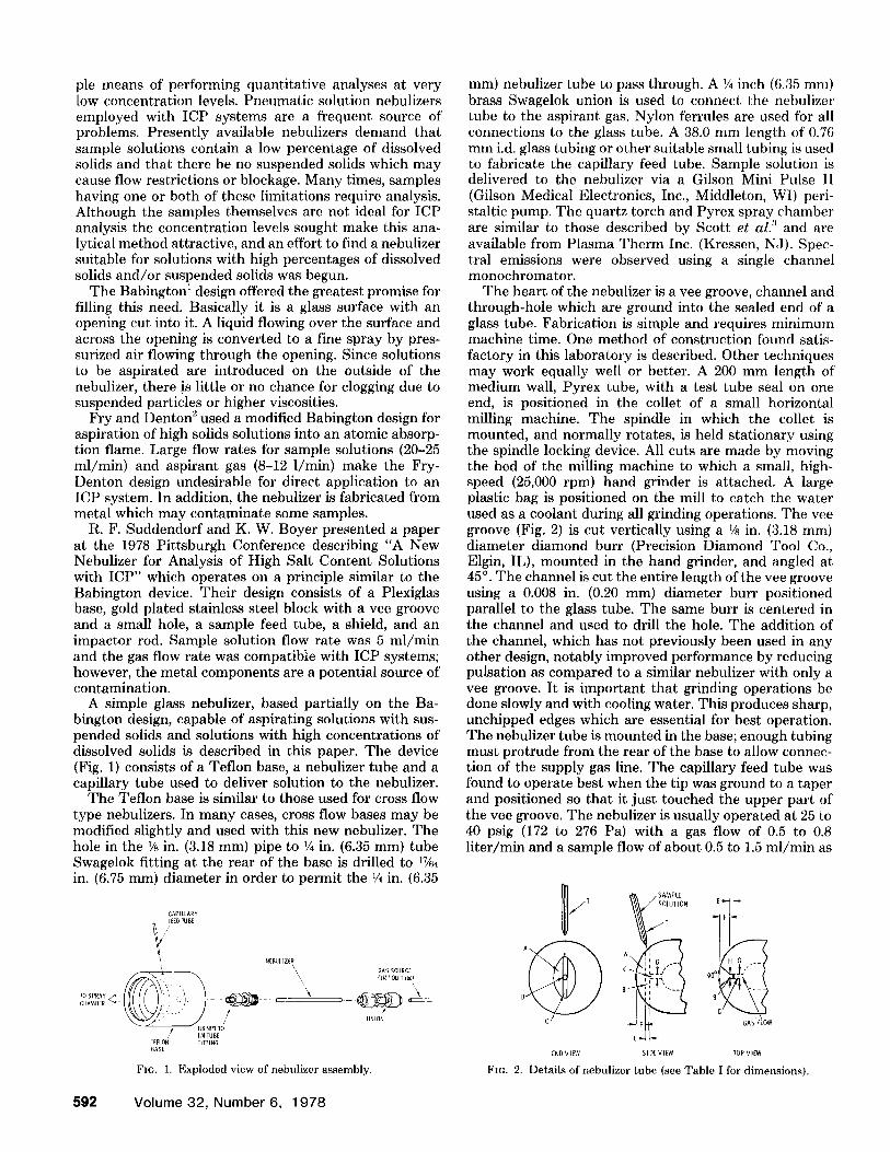
The heart of the nebulizer is a vee groove, channel and through-hole which are ground into the sealed end of a glass tube. Fabrication is simple and requires minimum machine time. One method of construction found satis- factory in this laboratory is described. Other techniques may work equally well or better. A 200 mm length of medium wall, Pyrex tube, with a test tube seal on one end, is positioned in the collet of a small horizontal milling machine. The spindle in which the collet is mounted, and normally rotates, is held stationary using the spindle locking device. All cuts are made by moving the bed of the milling machine to which a small, high- speed (25,000 rpm) hand grinder is attached. A large plastic bag is positioned on the mill to catch the water used as a coolant during all grinding operations. The vee groove (Fig. 2) is cut vertically using a 1/8 in. (3.18 ram) diameter diamond burr (Precision Diamond Tool Co., Elgin, IL), mounted in the hand grinder, and angled at 45 °. The channel is cut the entire length of the vee groove using a 0.008 in. (0.20 mm) diameter burr positioned parallel to the glass tube. The same burr is centered in the channel and used to drill the hole. The addition of the channel, which has not previously been used in any other design, notably improved performance by reducing pulsation as compared to a similar nebulizer with only a vee groove. It is important that grinding operations be done slowly and with cooling water. This produces sharp, unchipped edges which are essential for best operation. The nebulizer tube is mounted in the base; enough tubing must protrude from the rear of the base to allow connec- tion of the supply gas line. The capillary feed tube was found to operate best when the tip was ground to a taper and positioned so that it just touched the upper part of the vee groove. The nebulizer is usually operated at 25 to 40 psig (172 to 276 Pa) with a gas flow of 0.5 to 0.8 liter/min and a sample flow of about 0.5 to 1.5 ml/min as
l i t
B
GAS FLOW
END VIM SIDE Vt~ TOP VfEW FIG. 2. Details of nebulizer tube (see Table I for dimensions).
592 Volume 32, Number 6, 1978
T A B L E I. Dimensions and operating p a r a m e t e r s .
Item"
A (vee groove) B (channel) C . (orifice) T (capillary feed tube)
in. iT/m
E (depth of vee) 0.015-0.035 0.4-0.9 F (depth of channel) 0.004-0.012 0.1-0.3 G (dia of orifice) 0.008 0.2 H (width of channel) 0.008 0.2
Gas pressure 20-60 psig (138-414 Pa) Gas flow 0.4-1.2 liter/rain Solution flow 0.1-2.0 ml/min
" Letters refer to Fig. 2.
determined by the pump setting. The sample flow rate for this new nebulizer is only about 5% of that used by the Fry-Denton device and about 20% of that used by the Suddendorf-Boyer design.
Full optimization of this nebulizer with an ICP system has not been completed. However, sufficient data have been collected to demonstrate that the nebulizer is com- patible with ICP systems. Although analytical require- ments vary from laboratory to laboratory, several appli- cations from this facility are cited to illustrate the capa- bilities of the nebulizer. Detection limits for Fe, Mn, Si, P, La, Tm, Na, and Ni, in 99% aqueous solutions, were within a factor of 2 when compared to the same ICP system using a Plasma Therm cross flow nebulizer. (Other elements have not been checked). The nebulizer has been used on a routine basis with an ICP system to analyze several types of solutions containing approxi- mately 20% dissolved solids. Solutions containing 50% dissolved solids have been nebulized; however, solidifi- cation of sample on the torch tip and problems associated with induction coupling constitute limiting factors. Sam- pies with suspended solids can be atomized without clog- ging the nebulizer. Undiluted, commercially available milk of magnesia was easily nebulized; however, sample solidification on the torch tip was again a problem. Sam- ples with high pulp content such as canned grapefruit juice, apricot nectar, and tomato soup have been nebu- lized. Spectral emissions for sodium and calcium in these samples were unstable while signals for iron were quite acceptable. The cause of these instabilities is not known, but ratioing to an appropriate internal standard may prove helpful. The effect may also be a function of the
size and/or number of particles carried into the plasma. Undiluted, evaporated milk was atomized with the new nebulizer yielding signals for calcium and magnesium which were not stable; however, a l : l dilution of the milk samples resulted in stable signals for both elements. Since oils are not analyzed in this laboratory, the only tests conducted were to nebulize oils of various viscosities for the purpose of determining the ability to produce an aerosol. Light-weight oils (Saybolt viscosity -100 s at 100°F) were easily atomized. Unused SAE-20, -30, and -40 weight motor oils worked very well when diluted l: l with xylene.
It should be mentioned that, although gas flow and sample delivery rate improvements have been shown in this paper, some sacrifice in the size of suspended parti- cles may have to be made when compared to the Fry- Denton design. Reasons for this sacrifice may be smaller bore feed tube, differences in spray chamber configura- tion, and the smaller volume of nebulization gas used in an ICP system.
The dispersing element was a Varian Techtron model AA5 0.5 m, Ebert mount monochromator (f/10) using a 50 mm by 50 mm grating with 638 grooves/mm (33 /t~/mm, first order) and blazed at 4000 to 5000 A. Elec- tronics consisted of a Hamamatsu 955 photomultiplier tube (Hamamatsu Corp., Middlesex, NJ) Keithley model 244 high voltage power supply and Keithley model 417 picoammeter (Keithley Instruments, Inc., Cleveland, OH), Houston Omniscribe recorder (Houston Instru- ment, Austin, TX), and a Dymec model 2401A integrat- ing digital voltmeter (no longer manufactured).
A modified nebulizer similar to the one described for ICP use was employed on an atomic absorption speS- trometer (Varian Techtron Model AA6). Only a limited amount of effort has been expended in this area and, although sensitivity and precision were found to be in- ferior to the commercial atomic absorption nebulizer, it is believed that optimization of parameters and the use of a different spray chamber would improve precision and sensitivity.
ACKNOWLEI)GMENTS
R. L. Negus and J. Wintersberger of Sandia Laboratories furnished valuable infbrmation on nebulizer design and glass grinding techniques.
1. Popular Science, May 1973, p. 102 and R. S. Babingtcm, [L S. Patents 3,421,692; 3,421,699; 3,425,058; 3,425,059, and 3,504,859.
2. R. C. Fry and M. B. Denton, Anal. Chem. 49, 1413 (19777). 3. R. H. Scott, V. A. Fassel, R. N. Kniseley, and D. E. Nix(m, Anal. Chem. 46,