22
,. LA-11956-MS UC-706and UC-741 Issued: December 1990 LA--I 1956-Ms DE91 004297 A Simple Plane-Wave Explosive Lens }. N. Fritz .. ./
,.
LA-11956-MS
UC-706and UC-741Issued: December 1990
LA--I 1956-Ms
DE91 004297
A Simple Plane-Wave Explosive Lens
}. N. Fritz
..
./
1. ,,
.,
....,,.,. , .:., !., ,
A SIMPLE PLANE-WAVE EXPLOSIVE LENS
by
J. N. Fritz
ABSTRACT
A simple plane-wave lens, using an inert central plastic wave shaper, has beendesigned. An experiment was done with a 4-in. diarn, zeroth-order design.An iterative technique that uses measured time deviations to correct thenext wave shape was developed. Two identical versions of the first iteratedshape were fired. Arrival-time deviations in these !irst iterates fell within50-ns bounds. With greater care and further iteration, lensesbound by Ideviations seem possible.
INTRODUCTION
Current explosive lenses, although successful, have problems; they tend to b~ ?xpen-sive. Required rigid tolerances and concomitant machining costs account for muc!. ~f theexpense. Complex explosive formulations make uniform production difficult.
Most explosive lensesl operate by transforming the spherical wave fron a single det~nator to a plane waveby using a central explosive, with a slow detonation velo. ity, boundedby a sheath of explosive with a faster detonation velocity. For a certai, shea:h angle, thefast detonation velocity of the outer explosive, expanding on a sphericalfront, induces a flatwave in the central explosive that is moving at its detonation velocity. ring an explozivefor the central part of the lens is an advantage because the detonation vebity, D, is notdiminished by attenuations coming from the rear of the lens. The faster external explosiveusually overdrives the internal explosive. This again should r~ult ix a relatively constantD, because the tangent Chapman-Jouget condition implies a slowly va ,ing D for relativelywide-pressure excursions, A slow detonation velocity fo= th~ inner explosive results in awide aspect for the lens (Din/DOut = cos 0, where Q “.,the half m gle of the outer sheath).This allows the use of a minimal amount of the high-detonation velocity (an-i usually moreenergetic) explosive, which is an advantage. Baratol, a TNT/Ba (N03)2 ~ixture, servedthis purpose admirably in the old P-xx lenses. It is now d a h waste because of the barium content. Currently, a mixture of TNT/CaC03/microballoons/talc isreplacing Baratol.
Another way2 of delaying the centrai dome of the spherical wa~? is to use an air gap.A donor explosive accelerates a metal plate. The shaped metal runs through the gap andlands simultaneously on a flat acceptor explosive. Because of the large difference betweenthe free-surface velocity of the metal and detonation velocity in explosives, tolerances inshapes and positioning of t components of the lens are extremely tig’ .i.
,..— —————.—.— _————.———
The design for a lens we present here is directed toward shnplicity and economy. Wepresent the results of preliminary designs and experiments.
THE BASIC IDEA
Our idea for a lens is shown in Fig. 1. We use an inert material instead of an explosivefor the central wave-shaping mechanism. All of the complicated machining is concentratedin the curved surface of part B. Once a shape has been finally determined, this part couldbe fabricated by molding a suitable plastic. A final bit of machining would probably berequired to make the shape true.
ED
I
c
I F
r
Fig. 1. Schematicof Lens. A - acceptorexplosive,B - plasticwaveshaper,C - donorexplosive,D - detonator,E - detonatorsupportandlid forexplosive,F - plasticcylindertohold in explosive.
For the donor explosive, we envision a material that can be poured or pressed intothe lens and, in this process, conform to the shape of part B. Liquid TNT could be pouredinto the donor explosive cavity. A plastic capable of withstanding this temperature andchemical environment is doubtless available. One should try to match thermal expansionsof the explosive and plastic. This is presumably an easy job since they are “similarnorganicmaterials. Freezing of the liquid TNT should be by thermal conduction through the flatface of part B. The practicality of this needs to be investigated.
In a lens of this type, where precise timing depends on constant material properties,it is important to choose materials that lend themselves to tight specifications. An ex-pbsive with a single chemical component such as TNT (almost a single component) hasan advantage in this respect. Some of the consistent, modem, pelletized explosives, withtheir excellent pressing properties, are also candidates fo- the donor explosive.
Simpledesign for preliminary experiments dictated a cylinder for part F. Much of theupper explosive in the outer run is probably unnecessary. A cone, or some other shapethat minimizes the upper explosive, could be used. This would also depend on how thedonor explosive is packed.
2
—-.
For our preliminary experiments we used composition C-4 for the donor explosive andPMMA (polyrnethylmethacrylate-plexigl~) for the plastic parts. A thin layerof PBX 9501was used as an acceptor. The detonation wave in the acceptor transmitted a shock througha thin layerof Al. Arrival times over the face of the lens were recorded by flash gaps on theother side of the Al. The preliminary design used a simple lens formula and ray tracing,with constant velocities for the media. An iterative procedure was then used to correct theshape of part B, using measured time deviations from planarity. In this latter procedure,everything is kept fixed except for the position of the interface between the donor explosiveand part B.
INITL4L DESIGN AND RESULT
The radiusof curvature of the central part of the wav-shaping plastic can be obtainedfrom the simple lens approximation (see Fig. 2). This approximation is valid for a smallregion about the optic axis where the sagittae of the arc, z. is adequately given by y2/2R.The spherical wave from a point detonation a distance P away from the interface arrivesat the interface at tl. At a time At later, the wave a+ the edge of the shown arc contactsthe interface. We have (ZP + zR)/’D = (ZR – zQ)/uS. This gives the simple lens formula(~~)-’ + (Qus)-’ = (u;’ – D-l)/RL. To get a flat wave, Q = 00, and we get RL =
P(D/u. – 1). D *
Fig. 2. Simple lens approximation for central part of lens,
We concentrate on a 4-in. diam lens, the equivalent of a P-40, with P = 3 in. This isprobably more explosive than is necessary on the optic axis and is a parameter to inves-tigate in a more general study. Properties of composition C-4 explosive are not that wellknown. Initially, we chose D = 8.0 mm/Ps for the composition C-4 detonation velocity,and US-= 6.5 mrn/ps for the shock ve!ocity in PMMA resulting from the C-4/PMMA in-teraction. This gives RL = 0.692 in., a discouragingly small radius of curvature. However,it only applies to a small region near the optic axis. To get a better idea of our lens shape,we need to go to a ray-tracing approximation (see Fig. 3).
At t = O, the spherical wave has just touched the plastic surface. We have at time t,I?(f) = P+Dt, Ay = u~t, and Z2+ (P + Ay)2 = Rp. Hence, t = Ay/us, R = P + DAy/uC,and Z2 + (P + Ay)2 = (P + DAy/u.)2.
3
l—x~ -\\
Fig. 3. Ray-tracing ocheme for calculating lens shape.
We then have
(1)
For smal! z, Ay ~ ~usz2/(P(D – uS)). The radius of curvature is P(D – u.)/u.,agreeing with the simple lens approximation. For large z, Ag x SZ, s = (u~/(D2– u:)) 1/2,i.e., the lens tends toward a cone, not the sphere of the simple lens approximation. Forour initial numbers, s = 1.394. Figure 4 shows computed shapes using Eq. (1). For ourexperiment we chose P = 3.0 in. A valueof 2.0 in. and possibly 1.5 in. would probablyhave been a sakchoice.
CAo~ v~~~ ~ the plastic k not constant. Due to the iinite thickness of the donorexplinsivekthe shock wave gradually attenuates on the optic axis after it enters the plastic.As @r? duxrmmion wave moves farther on the radius of the plastic lens, the interaction~n the~iosive and plastic changes from normal incidence toward tangential inci-denme. Both of these effects cause the real wave to lag behind the calculated flat-waveposition. A reai detonator has finite size. We do not have an ideal point detonation. Weaccount for this by positioning the front surface of the detonator 3/8 in. (-10 mm) nearerthe plastic lens rather than at the Wnrn position of the point detonation. This numberwas chosen somewhat arbitrarily. One could do better by considering the actual shape ofa detonator and its internal construction.
Because of perturbations and uncertainty in the properties of C-4 explosive, we needdata from an experiment. Figure 5 gives our ~xact initial configuration. We do not expectsuccess on the first try. The measured & WH be used to estimate the correction 6y. Wewill keep everything in the configuration cor:dant except for the upper shape of the plasticlens.
o
K“’’’’’’’’’’’’”—
~~
!-140r I I 1 10
I10 1
20 30 40 50 sox-lensr a(
Fig. Plastic lens shapea at varying exploaive thicknesses km a point detonation. Notethattheverticalscaleis compreaeed by about a third.
—
Fig. exploded view of our firet design. The piecea are drawn approximately to scale.The dotted line indicatea the correction made for the aecond design.
Seven slits, spaced 0.5-in. apart, recorded the arrival of the shock on the surface ofthe aluminum. Figure 6 shows the streak-camera record obtained. The axial symmetryof the lens is evident. The slit plate was not quite centered on the lens, evidenced bythe pattern of peak-lags from the traces shown in Fig. 7. This affects the side traces, buthas a negligible effect on the central trace. The resulting time-lags for various regions
of the lens are shown in Fig. 7. The radial location of a timelag is obtained from theimage magnification. The film may have been read slightly tilted; there were not any goodstreaks to align the time-axis on the film. The effect cf this angle error (cos e type) onour results is negligible.
42, 1 1 # r I-a ,& ; .ti’ 1
= : i’.~~ ; .,,\
32 . . i “, ‘-1 126 28 30 32 34 36 38 40
XG (mm)
Fig. 6. Streak camem record, lens 1. Seven tmcee, 0.5-in. apti, record lightfromtheflaahgapsabovethealuminumsurfhce.If therecordhadnot beensweptin thex-direction
mm/#a , the traces would all have fallen on the dotted lines. The x-displacement of theitmr.e, from t e dotted lime, yielda the time-lag for the wave arrival. The spacin between
[the dotted lines (1,313 mm/O.5 in.) gives the magnification fc,f the image, 0.1034 *1%).
We had a time differential of 0.80 W. The 1ag was probably due to the expectedattenuation caused by the Taylor wave and, in part, to our uncertainty for the value ofDua/(D – u.). Our guess for this value is 34.7 mm/K. On a more positive note, the tracesare very smooth. The scatter about a given trme is -020 ns. If we wmt to control the lagtime, 6t,by moving the interf=e, 61J,the ~elociW” 6v/6t ~ Du./(D – u,) is pertinent.The value 34 mm/w implies a tolerance of 1.5 mm/W m. That is, for a relatively lowtolerance, we have a tight control on the timing. The lag measured in the firatexperimentimplies we have to “scalp~our lens by about an inch. This greatly improvesour aspectratjo and will ultimately allow use of less donor explosive.
m, 1 T 1 1 1 , 1
m3
—
I
0
.
0
-
0
00
0
0~v
0
0
0
T i mL aI
o
0
.. 0 f rt r4
v p ev afromo tt r
:
LensRad;us(i;.)’
Fig.7. Lene1 timdage.
The edge of the donor explosive is a sharp-edged cone
I 2
pointing toward the acceptorthrough 0.2~ in. of plastic. At-this point, a side rarefaction starts working inward towardthe center, relieving the wave and caus”mga lag in time. This influence is clearly shown inFigs. 6 and 7. The influence extends inward to a radius of i.6 Fn.and 1.7 in. (definitely).A 4S0 rule, for Ioss due to unsupported plastic run, seems to be in effect. If we wanted afull 2-in. radius of flat wave, we would clearly have to extend the explosive radius to 2 in.+ thicknessof plastic run.
DESIGN TWO AND RESULTS
We
we
We pay more attention to the equation of state of composition C (C-4) and Phave3 for C-4,
Po = 1 .g / c, D = 8 .m m, a PCJ = 25.7 Gpa (ca~c.) .
fit a simple q-law EOS (4) to the parameters,
poD2 D2m = — – 2 = 2 . 5a nq = -
P Z + 2)= –3.0656 J/mg .
The M f i u for the EOS of PMMA,
= 1.186 g/cm3 , u, = 2.598 + 1.516 up mmlps , qc = 1.5 .
We used this data and the ray-tracingcode MACRAMEto calculate the ID behaviorof the lens along its central axis. Results are shown in Figs. 8-11. The time-lag measumdin the experiment can be attributed to the lag produced by the decaying wave in thePMMA. The inert, mock-explosiveHugoniot gave the initial pressure in the explosive as140 kbar. This was sufficient co insure prompt initiation, with a run to detonation of<0.1 mm, in the PBX 9501 acceptor. The ability of the plastic at state B to initiate theacceptor is an important consideration in lens design. This assures a uniform pressurewave is transmitted into the adjacent material.
-o
-7.966gI
.
K(
TaytorWave V8 in A16061- - “
P8X9501--
./ . .. . 2 5/8 in. 2 ~ I I
tllllll loll i I IIL L II I ILI! ‘11,1,I
8 - -40 -20 0 2.0 40 60y ,Lag.coor.(mm)
L
80
Fig. 8. MACRAME ID, wiwe-approximation hydrocode) wava and interfacu along thelane axis (the “optical= axie). The Taylor wave emanating fimm the point detonation Ntmncated to the portion that contmla the lens behavior. Thedecayof theshock aa it tradethrough the plasticleadst a a r rt iat the acceptor exploeive 0.8S4 # later thanthe arxival of a nondecaying wave. We u mock explosi’m (a Hugoniot curve of an inertchemical match to PBX 9s01, PO= 1.87 g/crn3, = + 7G = 1.5) forWOreaeona.Firat, the initial prenu re in the mock Hugoniot lets us jud~ the Iike4ihoodof andrun to detonation of the acceptor exploaive. Second, MACRAME, at the moment,doeenc o r r ehandle an exploaive that haa been dmcked to a detonation.
8
, . , , , . ,
I ,., : ,.. .
- ——
,.
g1’ I
1 , , I 1 , , v I v 1 , , I -.
Inm
In
1 MockHF. PMMA,
!1 1 , , 1 , , 1 , * , ,
0 0 1 1.5 2 2.5
Fig. 9. MACRAME P - up interactions. The C-4 ●xploeive, at ita C-J point, interactswith PMMA to prodnce state A. As the wavelete in the exploeive Taylor wave catch up tothe lead shock in the PMMA, its strength decaye to etatc B. This state interacte Witb themock-explosive lhgoniot to get 0t8te C.
om
o.
r r I I I 1 I I
P“ Lead Shock Pi
I.~ -
/ cF -. \ \‘.*[ ,,’=-.. .r~ fl$Y=-0224GPefnunb 11
\BwA1
i I/rr
[!
,
, 1 1
,
.
L--i10 0 10 2f) 30 40 50 60 70
Y ,Lag.coor.(mm)
Fig. 10. Lead chara,ctuistic prassm Pmeaur- alongtheleadahockdownthecentralhof thelensareahown. Statee & B, and C in the P — indicated. In tk actualhe, s t aC rapidly grows to a detonation in the acceptor explosive.
9

4/ -----+ u I
& - -0.0W4( Li
‘c’,/ \ ‘
/ PnklA
M o cI
t
. ~ .
A
I i
o{-lo 0 10 20 30 40 60 60 70
y ,Lag.coor.(mm)
F i11. Lead characteristic partich vdocitiu.
Clearly, if we had allowedfor the lag in the plastic, we would have achieved a muchbetter O~b-orderiens. We need an iterative method to go from measured timelags, &, tocorredions in the explosive/plastic interface location, @ We use the ray-tracing approxi-mation. In Fig. 3, we let ye be the thicknessof the kmsat the center (i.e., the position wherewe want the wave to be flat). Then, i a a radius z, we increaseA A = A + 6the change in arrival time (an earlier mival) wil! be given by
To first order in Jy we have
“ = ’ ’‘d - (
The (l/u. - cos e/D) factor in Eq. (2) varies from 39 ns/mrn on the “optic axis” to4 ns/mm out at the edge of our particular lens.
A spline fit to the 6t shown in Fig. 7 was mapped to 6y via Eq. ( The corrected lensshape is shown in Fig. 12. A quadratic fitto thisresult seems adequate. The machiningspecifications for the new lens is shown in Fig. 13.
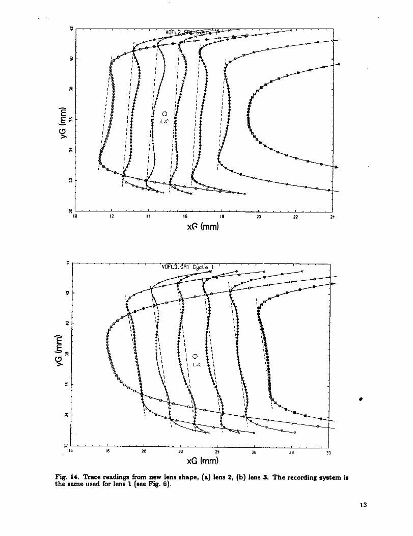
Two lenses were fabricated with the new shape and fired. Streak-cameraresults areshown in Fig. 14. We did not get the middle slit centered over the lens and the slits wereslightly tilted with respect to the streaking direction; however, this is not critical to theanalysis. Time offsets can be measured rdative to the dotted lines added to the figure.
a. .
!3
0
—-- — — . , . . .- -- —.r
I S ~\ AyO
Y
\f
\
., ..0
,/
\
...
\
quadratic -–..>fit
\——— L 1
. - 20 w
Radi& (mm)
Fig. 12. New lens ahape, firat iteration.
* r - —
/ \
i
\ \
- :\
TJ
I
- - o.1933x’ I~ i /’
G -; :
v%.
“\xm16461
t’ = - - \/“ “’, ; :
t; L
L. . . . . . . ___ . -, ——
. .. c I... ,
Lens R a
}“ig. i3. Specification for lens shape (dimensions in
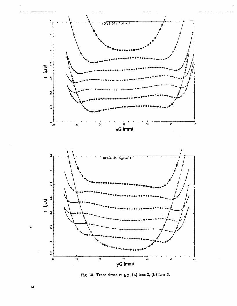
In this particular iteration of the shape, the outer, sharp wedge of explosive still producesa circle of earliest arrival that is readily apparent in the traces. Presumably, in a final~teration,this early arrival will be lost or ambiguous. Figure 15 shows the same recor&with the XC axis changed to time. Relative times along a trace are meaningful.
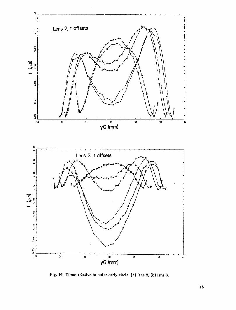
Figure 16 shows the f-offsets from a base, the dotted lines in Fig. 15. Lens 3 seemsmom evoluted in the center than lens 2, bui both have a. characteristic “M” shape. Inboth cases, the arrival-time spread is about 50 ns. The character of the deviation followsthe character of the deviation of our polynomial approximation, from the first calculatediterative shape. This is probably fortuitous because of the large size of our iterative firststep. ILdoes suggest that we ought to use a spline to represent our y-shapes rather thana low--orderpolynomial.
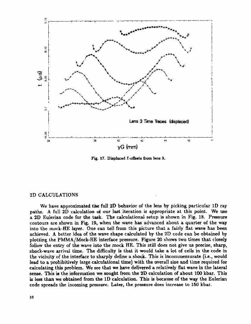
In Fig. 17, we plot the displaced traces (giving a 3D effect) from lens 3. The axialsymmetry of the deviation from simultaneousarrival is apparent. The outer portion of theretained trace is.the early arrival from the sharp wedge of explosive at the outer portionof the lens. (Actually, side rarefactions have cut into this wave and moved it in along the45° line from the wedge tip.) There is a circular region of lagging arrival and then, in thecenter, a dome of early arrival. We should have followed the precise spline for AyO+&y inFig. 12 for our machining specifications in Fig. 13! (This has to be fortuitous for such alarge, first-iterative step.)
1
y-
I
1
1’
11i
I
f’1I
1’I
I
;
t 1 , , ~
—
-f
s-
1 1 1 1 1 m 2 2
X (mm)
1 , , t
1 1 m 2 2 2 2 ?
8-
●
XG (mm)
Fig. 14. Trace readings from new lens shape, (a) lens 2, (b) lens 3. The recordingsystemisthe same used for lens 1 (see Fig. 6).
— —
‘+ “ v ’-N:
[
-t
TmA
.
N
Q -13 M 3 40 u 43
yG3~mm)
Fig. 1S. Trace times vs YG, (a) lens 2, (b) lens 3.
2-.. - ---— 7
I
.-..2
———- , ,I
yG (mm)
Fig. Times relative to outer early circle, (a) lens 2, (b) lena 3.
15
i
IiII
ii
1
!
Lens3 TmeT ( c SI
gr !$ L _ - —- - -, , , 1 —
3 4
yG (mm)
Fig. 17. Displaced Loffsets from lens 3.
2D CALCULATIONS
We have approximated the full 2D behavior of the lens by picking particular ID raypaths. A full 2D calculation of our last iteration is appropriate at this point. We usea 2D Eulerian code for the task. The calculational setup is shown in Fig. 1 Pressurecontours are shown in Fig. 19, when the wave has advanced about a quarter of the wayinto the mock-HE layer. One can tell from this picture that a fairly flat wave has beenachieved. A better idea of the wave shape calculated by the 2D code can be obtained byplotting the PMMA/Mock-HE interface pressure. Figure 20 shows two times that closelyfollow the entry of the wave into the mock HE. This still does not give us precise, sharp,shock-wave =rivai time. The difficulty is that it would take a lot of cells in the code inthe vicinity of the interface to sharply define a shock. This is incommensurate (i.e., wouldlead to a prohibitively large calculational time) with the overall size and time required forcalculating this problem. We see that we have delivered a relatively flat wave in the lateralsense. This is the information we sought from the 2D calculation of about 100 kbar. Thisis less than we obtained from the ID calculation. This is because of the way the Euleriancode spreads the incoming pressure. Later, the pressure does increase to 150 kbar.
16
x
6
4
2.00
0
~“ 12.00. 1 08 .6 .4 2 0
c the lens. The explosive ia detonated by aHuygens c at the detonation velocity D. This is shown in the explosiveI.mnponent. AISOshown are the plastic containing wall, the plastic w ehaper,anda layerof acceptor mock HE. Dimensions are given \n cm.
34
d 5 e50
\
75
0.0y (cm)
Fig. 19. Preasure contours 16.5037 # after the point detonation.a, b, c, d, e, f g h = OS, 17,34,50,7s, 100,116,133kbar.
17
—
,.
— ..——
. .
0 .- . - - - - - - -- -. - -- - ;- - - - - -- , - -. - . . - . . . . - -
0.05----------------:---------- .-.---;-.---.-...-... ..;..... ..-..-.....:. .. .. . .. . .. ...:. . .. .. . .. .. ....
0.00 ‘ .~\0.0 1 2.0z 4.0 5.0 6.0
x~~m)gL ..
0 .“ - - - - - - - - -- - - - -“..
=
T I..--........----...-r.........................--0.05‘-----”----------;------------- ---{----------------;------------ ----+--------- --;----------------
0 I0 1 3.0 4.0
x(cm)
Fig.20. Preeaureaat theinterface between thelens andthe (mock)
Wegive afurther display of the calculation in Fig.21. Ifweofa half height of50kbar) as arepresentative ofwhere the sharpagreement, qualitative and quantitative, with the measured dispersion in arrival times inthe experimental flssh-gap analyzer.
5.0 6.0
acceptor exploeive.
take thee-contour (sortshock should be,weget
x
.
—
P f e:$: c o u
--
y (
Fig. 21. Expanded vemion ofFig. 19; but slightly earlier, t = 1 6~s. Thepreaaurecontours in this plot are: u,b,c,d, e = 1, 5, 10, 20, 50kbar. The spacing between the dotted
c a for shock transit HE.
1

.—
DISCUSSIOIYAND CONCLUSIONS
We stoppea with this iteration. Our intent was not to perfect this particular lenssystem. but rathe~to demonstrate that this particular concept for a lens could readily bedeveloped into a reliable and Economical plan~wave lens. (The lens we arrived at on thetirst iteration would actual!:~l,. quite useful for many applications.) Clearly, the iterationprocess we used removes time lead” and lags in an adequate manner. We have a “coars?”and a “fine” tuning knob. ‘l’he iterative process is the “fine” tuning and is a success becauseof the large ~alue of the phase velocity,
byint,~aC,/’& = u,D/(D – U8) = 35 IKlII@3 .
We r t and still get 10 to 2 iimits on 6t. Thecoarse knoh is “keeping the rest of the lens constant.” This is where troubles will comefrom. Fan~i~a] quality control may be required to take full advantage of the fine-tuningcapahilitv. W-ehave not done a “complete engineering” job on the back side of the lens.Details of the back side of the lens will aflect the wave shaping in the lens. Fluctuationsin these details will result in fluctuations in wave shape. The back design should minimizesuch tran~ers in the fluctuations. We have not fully explored this problem. We list someapparent advantages and disadvantagesof this type of a lens.
Advantages
. All of the expensive free-form fabrication is done on an.inert material, the plastic lens.
. For production runs, a mold can be made for the plastic lens. Final machining wouldjust be ‘trueing LIp the final shape.”
● There is essentially no metal in the lens, hence no dmapnel.
. The wave is smooth; there are no small wavelength perturbations.
. Given the smoothness of the wave arrivaland the firwtmningapaibility, a wave arrivalflat to 10 ns seems possible. Smoothness to this 1e&’will:&p@&l on reproducibili~in the “back design.”
Disadvantages
. Changes in back conditions may affect wave arrival.
● The shock delivered by the fiat part of the plastic lens might (depending on theexplm.ive/plastic combination being used) be weaker than a fully explosive lens. Anacceptor pad of readily detonated HE could be required as a second component of thelens.
. Such a lens will probably be bulkier than a fully explosive lens. However, it is notclear at this point as to which type would require more explosive.
● At this time, design and methods of fabrication have certainly not been completelyworked out. Because we currently have successful, fully explosive lenses, this may bea fatal disadvantage. That is okay. Our intent here is to document the work done onan alternative approach.
PRESCRIPTION FOR DESIGNING A LENS
A production model for a lens with an inert plastic center will probably not resembleour prototype in shape, choice of explosive, or choice of plastic. Accordingly, we summarizehere the steps we went through (or ideally should have) with possibly helpful suggestions,mostly in the form of questions.
1. Do the complete back design. Choose the explosive plastic combination that one isgoing to use. Are you going to press, pour, or pack the HE? What shape do you wantand what can you get for the back surface of the explosive? How do we attach thedetonator? .What mechanical components, if any, are necessary to hold the explosiveand the lens? Are the fabrication processes easy (or possible)? How does the lensattach to the rest of the explosive assembly? We want a lens that will deliver a flatwave to a circle of radius ZO. Having gone through all this we arrive at some design,schematically shown in Fig. 22.
2. Presumably, we know the constitutive equations for the explosive and plastic. Weknow D. We calculate the initial interaction between the explosive and plastic andget the u. in the plastic.
3 Pick the P dimension. We want to get it as small as possible and yet still have enoughstrength in the shock coming out of the bottom of the lens to promptly initiate theacceptor explcsive.
4 Calculate shape 1 using Eq. (l). We calculate it so that point Q has an z sufficientlygreater than ZO. Probably, we would take z~ = ZO+w, where w is a dimension chosenlarge enough for mechanical stability.
5. Using some ID hydrocode, calculate the lag, 6tOp,on the optic axis due to the Taylorrelease wave in the explosive. We correct shape 1. We subtract from it a q.ladraticin z that vanishes at Zq and has the value 6YOP= 6topu8D/ (D – udj at z = 0. FO~a sma!i P, step 5 may require some judicious iteration to get the attenuation in theTaylor wave (a function of P) and the calculated shift in y to be compatible.
We now have a Oth-orderlens. At this point, it would be appropriate to do a 2Dcalculation of its behavior. If we run into some basic incompatibilities in the back design,we make suitable changes and go back to step 1. So far, this has been cheap and easy, nowwe need to
6 Fabricate the lens and test it. Subsequent lenses have shapes corrected by Eq. (2),which now has the iterative form
6ya+l = 6tiu~D/(D – u.cose) .
hdet.
~ t;;:;j.’:.,:,,:::;”’:.,;,,:~,....... : ... .-.+ .... . . . . ... .
Fig. 22. Schematic of a lens deaign $/o = AV(ZQ)+ W.
ACKNOWLEDGEMENT
I am indebted to J. E. Vorthman for managing the fabrication of these lensesand toS. P. Marsh for calculating the 2D behavior of the lens.
REFERENCES
1.
2
3
4
J. H. Cook, ‘Detonating Explosive Charge and Method of Impressing Surfacei Em-ploying Same,” US Patent No. 2,604,042, July 1952.
S. P. Marsh, “Explosive Plane-Wave Lens,” US Patent No. 4,729,318, M~h 1~.
B. M. Dobratz and P. C. Crawford, “LLNL Explosives Handbook, Properties of Chem-ical Explosives and Explosive Stimulants,”Lawrence Livermore National Laboratory,Livermore, CA, UCRL-52997 Change 2 (1985).
W. Fickett and W. C. Davis, ‘Detonation? University of Califomi& Berkeley (1979).
2
. S GOVERNMENT PRINTING OFFICE 19900.573036 201 15


