Page 1
Journal of Mechanical Engineering Research and Developments
ISSN: 1024-1752
CODEN: JERDFO
Vol. 43, No. 5, pp. 89-102
Published Year 2020
89
A Simulation Research of Heat Transfers and Chemical Reactions in the
Fuel Steam Reformer Using Exhaust Gas Energy From Motorcycle
Engine
Minh Quang Chau†, Van Vang Le‡, Anh Tuan Hoang††*, Abdel Rahman M. S Al-Tawaha‡‡, Van Viet
Pham‡*
†
Industrial University of Ho Chi Minh city, Ho Chi Minh city, Vietnam ‡
Ho Chi Minh city University of Transport, Ho Chi Minh city, Vietnam ††Ho Chi Minh city University of Technology (HUTECH), Ho Chi Minh city, Vietnam
‡‡Al-Hussein bin Talal University, Ma'an, Jordan
*Corresponding Author Email: [email protected] ; [email protected]
ABSTRACT: Onboard fuel steam reformer heated by the exhaust gas of an internal combustion engine has been considered
as an effective device to produce hydrogen (H2) for engine application. However, the fuel conversion efficiency of the
reformer is strongly dependent on heat transfer characteristics between exhaust gas and the reformer. Heat loss of the gas flow
along the exhaust system to ambient and the complicated heat and mass transfer inside the reformer with endothermic
reforming reactions strongly affect the reformer’s efficiency. Therefore, modelling study of heat transfer and chemical
reactions is thus necessary, as it is a powerful and cost-effective tool for estimating and maximizing the conversion efficiency
and hydrogen yield of the reformer. This paper presents the result of numerical study of heat transfer and chemical reactions
in the gasoline steam reformer integrated in engine exhaust system. An onboard compact gasoline steam reformer is made
and installed in the exhaust pipe of a Honda Wave motorcycle engine to produce hydrogen continuously by using the waste
heat of the engine for heating the reformer. The study accounts for all the aspects of major chemical reactions and heat and
mass transfer phenomena in the reformer. A computer simulation code has been developed for the study. The predicted result
was validated with experiment data. The results show that by taking advantage of engine exhaust energy, the optimum
operating conditions of the reformer under engine full load for high hydrogen yield are at mass water/fuel ratio of 3.5:1 under
space velocity of 1000/h. Under these conditions, gasoline conversion of up to 80% and H2 wet concentration of up to 46%
are achieved.
KEYWORDS: waste heat recovery, heat transfer, chemical reactions, fuel stream reformer, SI engine.
INTRODUCTION
The world is facing very serious problems from the overexploitation of fossil resources and environmental pollution from
means of transport. Countries are constantly introducing strict laws to control pollution problems from internal combustion
engines. Consumers are more concerned about fuel economy, and governments regulate fuel economy and emissions. Many
technical solutions have been proposed to reduce emissions from internal combustion engines such as equipping secondary
treatment systems [1], using optimal combustion strategies, and using alternatives [2]. The solution of adding hydrogen to the
combustion chamber is a solution that has attracted much attention recently [3]. The addition of hydrogen to the engine
combustion chamber can be done directly as a primary fuel, or indirectly by adding hydrogen through the intake [4]. However,
a major challenge and impediment facing the technology of adding hydrogen to internal combustion engines on motorcycles
is the storage and delivery of this fuel. However, a major challenge and impediment facing the technology of adding hydrogen
to internal combustion engines on motorcycles is the storage and delivery of this fuel. One of the most challenging issues
regarding H2 supplementation is how to provide it as a fuel additive for internal combustion engines. However, it is very
difficult to operate the catalytic converter in a gasoline engine at a low load, for several reasons. One reason is that the exhaust
gas temperature is too low to heat the format catalyst higher than the lamp shutdown temperature. Another cause is the exhaust
gas composition of conventional gasoline engines [5]. Many solutions are proposed that can bring the prospect of using
hydrogen directly on motor vehicles such as the modification of liquid fuel directly on the vehicle. One of the techniques that
can be used to recover waste energy from exhaust gases is fuel vapor reform, taking advantage of exhaust gas composition
Page 2
A Simulation Research of Heat Transfers and Chemical Reactions in the Fuel Steam Reformer Using Exhaust Gas Energy From Motorcycle Engine
90
and temperature. There are two main reactions, both endothermic chemical reactions that can confer the thermodynamic
benefit of the exhaust gas reclamation process. Those two reactions include Steam Reforming and Dry Reforming [6]. The
most preferred technology in this solution is steam reform. This technology can not only take advantage of the heat source
from the engine exhaust to perform reactions to carry out chemical reactions of steam with a catalyst to produce hydrogen
and a mixture of carbon oxides [7]. Hydrogen is a clean energy source that emits no CO2 and NOx, and its demand as a fuel
for fuel cells is increasing. Steam reforming of lower organic compounds such as methanol and propane is an effective method
for hydrogen production. The water vapor conversion of hydrocarbons is known to be a strongly endothermic reaction usually
performed on a Ni catalyst. That allows obtaining a hydrogen-rich gas mixture containing H2, CO2, CH4, CO, and H2O [8].
Along with the development of fuel handlers for new electrical systems, on-site hydrogen generation is also being investigated
as a driver of emissions control for conventional vehicles. In a particularly promising concept, known as the improved exhaust
gas recirculation, an innovator is integrated into an exhaust gas recirculation [4]. A relatively small amount of fuel is injected
into the reformer's upstream circulation, allowing the fuel to be converted to hydrogen (and CO/CO2) by reaction with water
vapor and air in the exhaust. The hydrogen-enriched gas stream is returned to the engine, where it can have some beneficial
effects. These include reducing NOx emissions from gasoline engines [6], disrupting the NOx-analytical balance in diesel
engines [7], and promoting the automatic combustion of various hydrocarbon fuels. Many studies have evaluated the effect
of reformed H2 on diesel and gasoline internal combustion engines. Ashur et al [9] studied the lean combustion characteristics
of a gate-injected gasoline engine using H2 from a plasmatron fuel formatter. Results showed that the plasmatron fuel reformer
with compact engine operation improved the specified thermal efficiency and reduced HC and NOx emissions [10]. The study
showed that the control of the reformer system is simple but the hydrogen concentration in reformate gas is low, reaching
only about 11% by volume. Aydin et al. [11] studied the particulate matter and exhaust gases in T-GDI engines using improved
onboard exhaust gas fuels based on high-pressure EGR. The results show that high-pressure R-EGR leads to reduced fuel
consumption and PM emissions [12]. The combination of steam and partially oxidized gaseous reforming gasoline with
additional air injection into the improved engine has a great influence on the fuel conversion efficiency of the improved engine
when the engine load is reduced [13]. Emission improvement using steam and enthalpy from hot engine exhaust is applied
using a compact system of fuel reformer integrated with a three-way catalytic converter. The Fuel Improvement Reactor was
tested online at several points operating the engine without TWC and at one point with TWC mounted at its core [14].
Hydrogen concentrations of up to 11% by volume can be produced in reformer products [15].
The reactions include complete and partial oxidation, water vapor conversion as well as gas-to-water displacement. These
reactions may be accompanied by others such as dry reforming and coking reactions. At the low temperatures, typical of
HCCI emissions, the equilibrium model of the reactions predicts a relatively low hydrogen content (less than 20% by volume)
in the product gas [16]. The application of this technique requires an active and stable catalyst that converts the feedstock well
over a wide temperature range. The composition of reforming is highly dependent on the reaction temperature, as well as
many other factors such as the catalyst formulation; reactor design; hydrocarbon-based fuels and gas preparations; and the
aging rate of the catalyst. All of these factors must be considered in future reform developments [17]. The hydrogen-rich
turbocharger with higher enthalpy than gasoline is fed to the turbocharger and is recirculated to the intake manifold i.e.
improved exhaust gas recirculation [18]. According to EGR improved performance test with a single-cylinder engine using
the conventional catalyst and modified catalyst, the improved catalyst shows good performance. Finally, to confirm the
efficiency of hydrogen generation and the effect of the real gas on EGR combustion, a single-cylinder engine with a fuel
modifier was developed.
This study focuses on building simulation and experimental models to describe the change of kinetic parameters of the
reforming process integrated on gasoline engines of motorcycles. This study evaluates the possibility of utilizing the exhaust
heat to perform the reforming process to improve the conversion efficiency of the system. The reformate gas composition was
considered to evaluate the reformer efficiency.
EXPERIMENTAL SETUP
In this study, a Honda motorcycle engine with a cylinder capacity of 110cc was used for testing on the Didacta T101D
hydraulic test bench. Technical parameters of motorcycle engines are described in Table 1. The engine load is generated by
the hydraulic consumable. The test bench system is equipped with a Johsai 9531 fuel consumption meter with an uncertainty
of 0.5%. In addition, the intake and exhaust airflow rates are both measured by suitable devices with a tolerance of 0.5%. The
testbed is used for changing engine load. It is also equipped with devices for measuring engine fuel and air consumption to
determine the exhaust flow rate. For the conversion process, part of the exhaust stream before TWC is redirected to the
catalytic inlet of the improver. In this flow, gasoline is injected for the reformation reaction. The remainder of the exhaust
Page 3
A Simulation Research of Heat Transfers and Chemical Reactions in the Fuel Steam Reformer Using Exhaust Gas Energy From Motorcycle Engine
91
stream was treated by TWC and then used for the second inlet of the innovator to heat the improved catalyst. It is cylindrical,
36 mm in diameter and 120 mm in length, filled with spherical Ni catalyst in the length of 85mm and spherical Al2O3 in the
length of 25mm. The catalyst specifications are shown in Table 2. The gas products generated from the steam reforming
process were determined by concentration through wet and dry infrared spectrophotometer analyzers with 98% accuracy. The
amount of hydrogen generated was calculated based on energy balance analyses. Besides, the oxygen concentration sensor is
installed on the intake manifold with an uncertainty of 0.5%. Determine the percentage of water participating in steam reform,
it is determined through the amount of condensate at the condenser. Confidence intervals using a 95% confidence level
reflecting the reliability and repeatability of the experiments were calculated based on the results of more than 12
measurements performed for each condition. Before testing, the engine was warmed up and measurements commenced when
a coolant temperature of 94 ± 0.5 °C and an oil temperature of 100 ± 2 °C were reached. The airstream temperature was
maintained at 40 ± 2°C throughout the test to reduce test-to-test variability. The exhaust gas temperature just downstream of
the exhaust valve is regenerated at the inlet of the reformer. It is the emulation of a tight coupling loop in a engine for which
the onboard reshuffle is intended to be used without any auxiliary heating device. The quantitative composition of the dry gas
stream was obtained by the internal standard method and confirmed with an online flowmeter. The catalyst is a nickel-free
formulation containing precious metals that are catalyzed by metal oxides. The activity of the Ni catalyst towards the limits
predicted by thermodynamics. Catalytic activities: activity, stability, activation, and deactivation of metals are studied.
It is possible to run a running engine using a previously determined reformer condition, altering the air, fuel, and emissions
to match those conditions to maintain steady hydrogen production. determined. Then further optimization can take place
where the conditions of the optimal reformer, for enthalpy, can be determined for the entire load range. However, the purpose
of this paper is to demonstrate the feasibility and benefits of closed-loop reform when applied to engines and optimization
studies that will be covered in the future.
Figure 1. Schematic of the experimental set-up
Table 1. Engine specifications
Parameters Specifications
Type of engine Spark ignition, 4 strokes
Number of cylinders 1
Swept volume 107 cm3
Bore 50 mm
Stroke 50.5 mm
Compression ratio 9.5: 1
Page 4
A Simulation Research of Heat Transfers and Chemical Reactions in the Fuel Steam Reformer Using Exhaust Gas Energy From Motorcycle Engine
92
Power output 7.2 kW
Revolution 7500 rpm
Table 2. Catalyst properties [19]
Nickel content, wt% 10
Alumina content, wt% balance
Surface area, m2/g 170
Total pore volume, ml/g 0.95
Size of the sphere, mm 1.86
Average crush strength, N 35
HEAT TRANSFER MODEL IN THE EXHAUST PIPE
By assuming quasi-steady, incompressible flow, the energy balance equation for the exhaust gas is written as [19]:
1
g g gp
g p g
T T qu
t x c V
+ = − (1)
For the exhaust pipe, due to its thin wall associated with high thermal diffusivity of metal, the radial temperature gradient in
the pipe wall can be neglected. The energy balance for the pipe wall is then written as:
2
2
2
p p gp cva rad
p p
T T q q q
t c Vx
− −= +
(2)
The heat transfers from exhaust gas to the inner wall:
1 ( )gp gp g ipq h d x T T= − (3)
Heat transfer coefficient hgp is determined by [20]; For a straight pipe:
1/2 2/3
( / 8)(Re)PrNu
1.07 12.7( / 8) (Pr 1)
f
f=
+ −for 104<Re<5x10⁶
1/2 2/3
( / 8)(Re 1000)PrNu
1.07 12.7( / 8) (Pr 1)
f
f
−=
+ − for Re<104 (4)
Friction factor (f) was determined by equation (5):
1 2.512log 0
3.7 Redf f
+ + =
(5)
The surface roughness ( ) is 2.59x10⁻⁴ for cast aluminum tubes.
For bend pipe, the effect of pipe bend is accounted for by the following equation [21]:
FB= 1
0.14
Nu 211
Nu Re
bent pipe
bent
d
d
−= + (6)
Hence, the Nusselt correlation in equations (4) should be multiplied by FB to account for the mentioned effects.
( )2 1
2
ln( / )io ip op
kq T T
d d
= − (7)
The heat transfer flux from the outer pipe surface to the ambient ( ) by free convection is:
cvaq
Page 5
A Simulation Research of Heat Transfers and Chemical Reactions in the Fuel Steam Reformer Using Exhaust Gas Energy From Motorcycle Engine
93
2 ( )cva cva op aq h d x T T= − ; 2
Nu acva
kh
d= (8)
The Nusselt number can be determined from the following equation [22].
2
1/6
8/279/16
0.387RaNu 0.6
1 (0.559 / Pr)
= + +
(9)
3
2 ( )Ra
op a
a
d g T T
−= (10)
where property is evaluated at temperature (Tp+Ta)/2, and property at Ta. The radiation heat transfer rate from the outer
pipe surface to surroundings is expressed as:
4 4
2 ( )rad op aq d T T x = − (11)
HEAT TRANSFER MODEL AND CHEMICAL REACTIONS IN THE REFORMER
Chemical reaction scheme and kinetic mechanisms
The overall reactions in the gasoline steam reforming process to form C, CO, CO2, and H2O may include the following
equations [23].
C8H18+8H2O=8CO+17H2; =1310 kJ/mol (12)
CO+H2O=CO2 + H2; -41kJ/mol (13)
C8H18+16H2O=8CO2+25H2; =933kJ/mol (14)
Kinetic mechanisms in gasoline steam reforming are very complicated. A detailed analysis of possible mechanisms is
presented elsewhere [23][24]. The most appropriate forms of reaction rate expressions for reaction (12), (13), and (14) above
for hydrocarbon fuel over nickel catalyst were found in the following form.
2
8 18 2
2
3
H CO21 C H H O2.5 2
e1H r
1p pkR p p
Kp Q
= −
(15)
2 2
2
2
H CO32 CO H O 2
e2H r
1p pkR p p
Kp Q
= −
(16)
2 2
8 18 2
2
4
H CO243 C H H O3.5 2
e3H r
1p pkR p p
Kp Q
= −
(17)
2 2
2 2 8 18 4
2
H O H O
r CO CO H H C H CH
H
1K p
Q K p K p K pp
= + + + +
where Rj (kmol/kg cat) is the rate of reaction j (j= 1 – 3); , , etc. are, respectively, partial pressures of gas species
C8H18, O2, etc., o e
jE
RTj jk k
−
= - the kinetic rate constant of reactions j (j = 1 – 3), in which k1, k2, and k3 are based on Xu and
Froment [25]. The kinetic data are shown in Table 3. koj is constant, Ej (kJ/kmol) - gas constant; T (K) - the gas temperature
in the reaction zone; Kej - the equilibrium constant of reaction j (j =1 – 3) and can be found in Table 4; -
the adsorption constant of species CO, H2, C8H18, H2O in reactions (12), (13), (14), which can be found in Table 5.
)298( 1H
= )298( 2H
)298( 3H
4CHp2Op
RT
H
ii
i
KK−
= eo
Page 6
A Simulation Research of Heat Transfers and Chemical Reactions in the Fuel Steam Reformer Using Exhaust Gas Energy From Motorcycle Engine
94
The rate of consumption or formation of an individual gas species based on reactions (12) to (14) is determined by summing
up the reaction rates of that species in all three reactions and considering the intraparticle mass transport limitations by
multiplying the rates (15) to (17) with various effectiveness factors 1, 2, and 3 [24].
As a result, the conversion rates of the individual species are as follows:
8 18C H 1 1 3 3r R R = − − (18)
2CO 2 2 3 38r R R = + (19)
2H O 1 1 2 2 3 38 16r R R R = − − − (20)
CO 1 1 2 28r R R = − (21)
2H 1 1 2 2 3 317 25r R R R = + + (22)
where ri is the conversion rate of gas species i (C8H18, CO2, etc.).
Table 3. Kinetic parameters [23]
Reaction koj (kmol/kgcat.h) Ej (kJ/kmol)
1 3.9951015 bar0.5 253150
2 2.059106 bar–1 72025
3 1.121015 bar 0.5 25462
Table 4. Equilibrium constants [24]
Reaction Equilibrium constant Kej
1 5.351012 exp(-11487/T) (bar2)
2 1.4110-2 exp(4685/T)
3 7.251010 exp(-21632/T) (bar2)
Table 5. Adsorption constants [25]
Species Koi (bar –1) Hi (kJ/kmol)
C8H18 6.4610-4 -3798
CO 8.3410-5 -7512
H2 6.6810-9 -8810
H2O 1.54105 bar 89132
Reformer modeling
The reformer is cylindrical, 35 mm in diameter and 120 mm in length, filled with alumina in 25mm and Ni catalyst in 85mm
of reformer length. Catalyst specifications are shown in Table 2. The hot exhaust gas flows around the reformer to heat it to
its operating temperature. In on-board steam reforming, since the reformer normally operates at a temperature lesser than
720oC, the heat radiation can be omitted. To simplify the model, one may assume that the gas properties and flow at the inlet
cross-section of the reformer are uniforms. The phenomena in the reformer include chemical reactions on the catalyst surface,
heat and mass transfers in the axial and radial directions of the reformer in the solid phase and gas phase. The pressure drop
is assumed to be negligible. With these assumptions, a reformer model is most appropriate to describe the reforming behavior
under the mentioned conditions. However, because in the axial direction, the dispersion coefficient is much smaller than the
gas velocity, it can be ignored without significant influence on the calculation results. In addition, the heat conductivity of gas
is much smaller than that of the catalyst bed, it can be omitted. Moreover, in the gas phase, the change of gas properties and
concentrations with time is normally much smaller than that with space, especially when the operation approximately reaches
to steady-state, hence it can be ignored within a small step time.
Heat transfer from the exhaust gas to the reformer wall is expressed by the energy balance equations for the control volume
of the exhaust gas in the exhaust gas site and for the control volume of the reformer wall, which are written as:
Page 7
A Simulation Research of Heat Transfers and Chemical Reactions in the Fuel Steam Reformer Using Exhaust Gas Energy From Motorcycle Engine
95
exh pexhexh
exh p exh exhz
qTu
z c V
−= − (23)
2
2
exh p p g
p p pz
q qT T
t c Vz
− =− = +
(24)
where uexh, Texh are exhausted gas velocity and temperature in the exhaust site; qexh-p is heat transfer from the exhaust gas to
reformer wall; ρexh, cpexh, Vexhz are density, specific heat, control volume of exhaust gas; T, ρp, cp, Vpz are temperature, density,
specific heat, control volume of the reformer wall; is heat transfer coefficient from the exhaust gas to the reformer wall
surface; qp-g is heat transfer from reformer wall to the gas in the reformer.
In the reformer, with the assumptions mentioned above, the basic equations of the model based on the mass and energy balance
for the gas phase and solid phase of the reformer are written as follows.
2
2
1i i idpi cat i
C C Cu D r
z r rr
= + +
(25)
g
g pg g pg h g( )gT T
c u c S h T Tt z
= − + −
(26)
2 2
b pb 2 2
1T T T Tc K
t r rr z
= + +
4
h g cat
1
( ) ( )j j
j
S h T T H R=
+ − + − (27)
where i denotes the gas species; j - reaction index; , , (kg/m3) - the densities of gas, catalyst, and bulk catalyst bed,
respectively; and (J/kgK) - the specific heats of gas and of the catalyst bed, respectively; - the void fraction of the
catalyst bed; (m/s) - the mass transfer coefficient of gas component i; h (W/m2K) - the heat transfer coefficient; T and Tg
(K) - the temperature of solid phase and gas phase, respectively; Ci (mol/m3) - the concentration of gas species i; r and z (m)
- cylindrical coordinates; Sh (m2/m3) - the heat transfer area per volume of catalyst bed; Hj (J/mol) - the heat of reaction j; K
(W/mK) - the heat conduction coefficient of catalyst bed; Ddpi - the dispersion coefficient of gas component i; u (m/s) - the
superficial gas velocity equal to the ratio of volume flow rate to the cross section area of the reformer.
The dispersion coefficient of the gas in a catalyst bed is dependent on molecular gas diffusion, bulk gas velocity, and pellet
diameter and can be determined based on Askcan et al. [26] as: 0.5idpi p
bed
DD d u
= +
; where dp is pellet diameter; Di is
gas diffusivity of species i to the mixture of the other gas in the reactor; is tortuosity of the bed and correlated to the
void fraction of catalyst bed as: 1
bed
= .
Based on the phenomena of the gas flow and operating conditions of the reformer, the initial and boundary conditions are set
as follows:
At t = 0: T = To; (28)
At reformer inlet face z = 0:
in
exh exhT T= , in
g gT T= ; in
i iC C= (29)
At reformer outlet face z = L:
g0; 0i
TC
z z
= =
; (30)
g cat b
pgc pbc
ihD
bed
Page 8
A Simulation Research of Heat Transfers and Chemical Reactions in the Fuel Steam Reformer Using Exhaust Gas Energy From Motorcycle Engine
96
At the centre r = 0:
g0; 0i
TC
r r
= =
; (31)
At the interfacial surface of the inner reformer wall and catalyst bed r = R:
0iC
r
=
; (32)
where Th is the temperature of the reformer wall; - the overall heat transfer coefficient through the reformer wall; K (W/mK)
- the heat conduction coefficient of the catalyst bed and gas, respectively. The properties of gas, & , depending on the
temperature and composition of the gas mixture. kg depends on the temperature and heat capacity of gas and, hence, also
depends on the composition of the gas mixture. Therefore, these properties vary from one location to the other in the reformer
and vary with time. They are determined from the properties and mass fractions of the individual species of the gas mixture,
whose properties can be taken from [27] as algebraic functions of temperature. Therefore, at each point in the reformer volume,
once the temperature and mole or mass fractions of the gas mixture are known, the overall properties can be determined.
The heat transfer coefficient between catalyst and gas, h ( ), is determined using Colburn factor [28]:
pg o
H 2/3(Pr)
c Gh J= (33)
0.51
H 0.91ReJ −= , (Re<50)
0.41
H 0.61ReJ −= , (Re>50)
o
geo g
ReG
S =
where Pr is the Prandtl number of the gas flow in the reformer; Go ( ) is the superficial mass flow rate, which is
defined as mass flow rate divided by the cross-section area S of the reformer.
The overall heat transfer coefficient through the reformer wall, K, is determined from:
1 1
i
b
K h = + (34)
where b is the thickness of the reformer wall (m); hi is the heat transfer coefficient on the inside of the reformer wall (W/m2K),
while is the heat conduction coefficient of the reformer wall (W/mK), which can be taken from [29]; hi is given by Cengel
et al. [30].
SIMULATION RESULTS AND DISCUSSIONS
Table 6. Exhaust gas parameters at the exhaust port
Engine load level 100% 75% 50%
Mass flow rate (g/s) 5.5 4.8 3.2
Temperature (degree C) 720 686 635
Exhaust manifold and mass-fuel ratio inputs are used as key inputs for the test measured at different loads at engine speeds
7500 rpm. Table 3 shows typical measurement parameters. Fuel supplied to the improved machine is equal to 5% of the fuel
consumption of the engine at full load, it is fixed at a flow rate of 115 g/h. The water-to-fuel ratio by mass (W/F) varies from
1 to 6. Therefore, at the highest gas flow rates, the corresponding spatial velocity of the gas is about 1100/h, which is much
smaller than the normal limit value of 16000/h required for the corresponding space velocity of a fuel reformer. Typical
modeling results are plotted and shown in Figures 2 to 8.
g pgc
KW/m2 HJ
)mkg/(s 2
m
Page 9
A Simulation Research of Heat Transfers and Chemical Reactions in the Fuel Steam Reformer Using Exhaust Gas Energy From Motorcycle Engine
97
(a)
(b)
(c)
Figure 2. Temperatures of exhaust gas, alumina pellet, catalyst pellet, and reformate gas in the reformer at full load with (a)
W/F= 2, (b) W/F= 4, and (c) W/F= 6
Variation of engine exhaust temperature, an average temperature of alumina pellets, the average temperature of the catalyst
and mean temperature of the gas in the turbocharger along the exhaust manifold and in the turbocharger at full load with W/F
= 2 (Figure 2a), W/F = 4 (Figure 2b) and W/F = 6 (Figure 2c). When increasing the W/F ratio, the exhaust gas temperature
decreased by 5% on average, the temperature of the alumina pellet also decreased by 2%, the temperature of the catalyst pellet
decreased by 1.8% and the temperature of the gas in the catalyst decreased by 3.2 %. When W/F = 6, it seems that the
fluctuating emissions are stronger, it is observed that the decreasing curve of the exhaust gas with many points fluctuates with
large fluctuations. Furthermore, considering the setting distance, the exhaust gas temperature decreases continuously but at
different rates corresponding to different pipe segments. The gas temperature does not decrease much at the 50mm section
because this section is short, the heat loss is only due to free convection at the outer surface of the tube. In the second segment
from 50mm to 100mm, the exhaust temperature decreases faster than in the first segment because heat loss here is not only
due to free convection but also to the fuel and heated water evaporating. In the third part, from 100mm to 150mm, the exhaust
gas temperature is significantly reduced due to heat loss for exothermic composite reactions by steam in the coil and free
convection at the outer surface. Aluminum pellets are placed in the front part of the improved machine at a distance of 20mm.
Page 10
A Simulation Research of Heat Transfers and Chemical Reactions in the Fuel Steam Reformer Using Exhaust Gas Energy From Motorcycle Engine
98
They are heated by exhaust gas but cooled by water and fuel that feeds the improved machine. As a result, the alumina pellets
are closer to fuel penetration and have lower temperatures. The catalyst pellet is placed 80mm after the alumina pellet in the
improved machine and is heated by exhaust gas but cooled by a very high endothermic composite reaction. As a result, the
catalyst temperature decreases continuously along with them for matter.
(a)
(b)
(c)
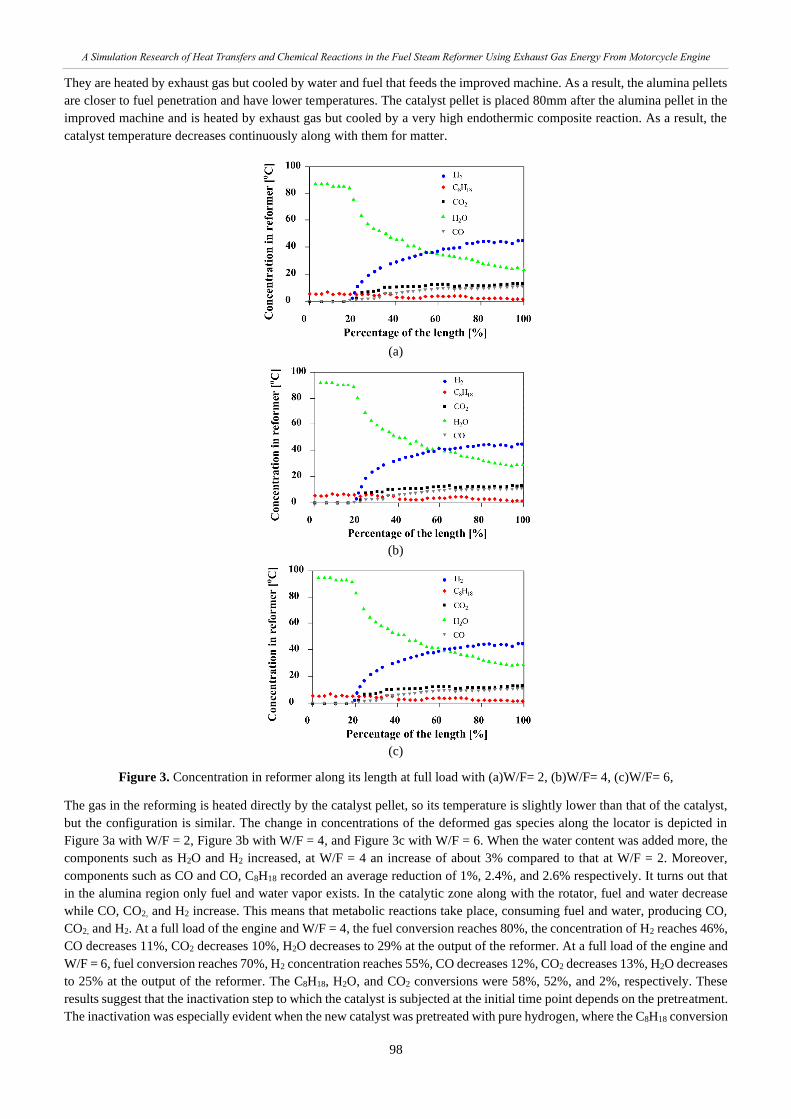
Figure 3. Concentration in reformer along its length at full load with (a)W/F= 2, (b)W/F= 4, (c)W/F= 6,
The gas in the reforming is heated directly by the catalyst pellet, so its temperature is slightly lower than that of the catalyst,
but the configuration is similar. The change in concentrations of the deformed gas species along the locator is depicted in
Figure 3a with W/F = 2, Figure 3b with W/F = 4, and Figure 3c with W/F = 6. When the water content was added more, the
components such as H2O and H2 increased, at W/F = 4 an increase of about 3% compared to that at W/F = 2. Moreover,
components such as CO and CO, C8H18 recorded an average reduction of 1%, 2.4%, and 2.6% respectively. It turns out that
in the alumina region only fuel and water vapor exists. In the catalytic zone along with the rotator, fuel and water decrease
while CO, CO2, and H2 increase. This means that metabolic reactions take place, consuming fuel and water, producing CO,
CO2, and H2. At a full load of the engine and W/F = 4, the fuel conversion reaches 80%, the concentration of H2 reaches 46%,
CO decreases 11%, CO2 decreases 10%, H2O decreases to 29% at the output of the reformer. At a full load of the engine and
W/F = 6, fuel conversion reaches 70%, H2 concentration reaches 55%, CO decreases 12%, CO2 decreases 13%, H2O decreases
to 25% at the output of the reformer. The C8H18, H2O, and CO2 conversions were 58%, 52%, and 2%, respectively. These
results suggest that the inactivation step to which the catalyst is subjected at the initial time point depends on the pretreatment.
The inactivation was especially evident when the new catalyst was pretreated with pure hydrogen, where the C8H18 conversion
Page 11
A Simulation Research of Heat Transfers and Chemical Reactions in the Fuel Steam Reformer Using Exhaust Gas Energy From Motorcycle Engine
99
was reduced from 70% to 58%. The shutdown then stops and the C8H18 transition is stable. Activation treatment through
reforming conditions for new and old catalysts accelerates this steady state.
Figure 4. The concentration of gas at the outlet of the reformer at different W/F from 1 to 6 at full load
The change in the concentration of gas and water vapor components according to the W/F ratio is depicted in Figure 4. The
results show that the reformat gas concentration at the improver outlet at different W/F when engine full load. As can be seen
in the figure, an increase in W/F leads to an increase in CO2 concentration, an average increase over the whole range
considering about 40%. This means more gas-in-water displacement reactions take place. As a result, more H2 is generated.
However, the figure shows a decrease in wet H2 concentration. This may be due to the increased concentration of H2O in the
reformate gas. In each reaction system, although the conversion of C8H18 was largely below 100%, the detected H2 yield was
higher than the predicted yield. For example, more H2 is produced (8.4 mol H2/mol C8H18) at a moderate C8H18 conversion
(60%) than would be expected from thermodynamic predictions (6, 8 mol H2/mol C8H18 with 100% conversion of C8H18).
Furthermore, the results also revealed a decrease in hydrogen concentration with more water added. The cause is believed to
be a sharp decrease in exhaust temperature with increasing water content, which has been analyzed in Figure 4. Thus, choosing
an optimal W/F ratio to balance the criteria and especially increase the amount of hydrogen gas is very important. The data in
Figure 4 also revealed that the W/F = 3.5 ratio is the most optimal.
Figure 5. Gasoline fuel conversion at different W/F at full load
Figure 6. A mole of H2 and CO for 1 gram of fuel at different W/F at full load
The effect of W/F on fuel conversion efficiency and H2 and CO generation can be seen clearer in Figure 5 and Figure 6, which
show fuel conversion efficiency and the number of moles of H2 and CO produced per 1 gram of fuel at different mass W/F
under engine full load. With W/F=3.5, the highest amount (0.14 mol) of H2 is produced from 1 gram of fuel, and fuel
Page 12
A Simulation Research of Heat Transfers and Chemical Reactions in the Fuel Steam Reformer Using Exhaust Gas Energy From Motorcycle Engine
100
conversion efficiency reaches the highest value of 80%. Low W/F causes the lack of water for steam reforming and water gas
shift reactions. This causes low fuel conversion efficiency and high CO and low H2 generations. High W/F will demand more
heat for vaporizing water and the remaining heat for fuel reforming decreases, leading to the decrease in fuel reforming
reaction and therefore the decrease in fuel conversion efficiency.
Figure 7. Engine exhaust gas energy, catalyst mean temperature, and mole flow rate of H2 and CO produced by the
reformer at different load
The changing trends in engine exhaust energy, average catalyst temperature, and molar flow rates of H2 and CO produced by
the modifier at different engine loads are depicted in Figure 7. The results show that when increasing the load from 50 to full
load, the exhaust gas energy has a slight increase, about 2%, while the CO content has a very strong increase, up to 4 times.
As shown in the figure, it can be seen that increasing engine load increases exhaust gas energy because both temperature and
exhaust flow rate increase. This increases the heating of the catalyst and thus the temperature of the catalyst, which increases
fuel conversion efficiency and produces more H2 and CO.
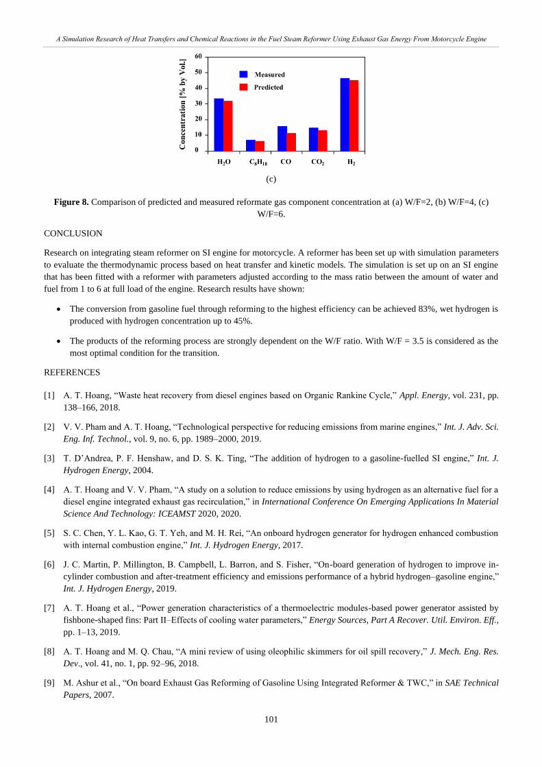
The results of the comparison of composition with a concentration of reformate gas components measured at W/F levels of 2,
4, and 6 at full load and 120g/h fuel flow rate are shown in Figure 8. The results show that there is a good similarity between
experimental data and simulation data. In general, the deviation between these two data sources is less than 5% and ensures
contrast ability and reliability.
(a)
(b)
Page 13
A Simulation Research of Heat Transfers and Chemical Reactions in the Fuel Steam Reformer Using Exhaust Gas Energy From Motorcycle Engine
101
(c)
Figure 8. Comparison of predicted and measured reformate gas component concentration at (a) W/F=2, (b) W/F=4, (c)
W/F=6.
CONCLUSION
Research on integrating steam reformer on SI engine for motorcycle. A reformer has been set up with simulation parameters
to evaluate the thermodynamic process based on heat transfer and kinetic models. The simulation is set up on an SI engine
that has been fitted with a reformer with parameters adjusted according to the mass ratio between the amount of water and
fuel from 1 to 6 at full load of the engine. Research results have shown:
• The conversion from gasoline fuel through reforming to the highest efficiency can be achieved 83%, wet hydrogen is
produced with hydrogen concentration up to 45%.
• The products of the reforming process are strongly dependent on the W/F ratio. With W/F = 3.5 is considered as the
most optimal condition for the transition.
REFERENCES
[1] A. T. Hoang, “Waste heat recovery from diesel engines based on Organic Rankine Cycle,” Appl. Energy, vol. 231, pp.
138–166, 2018.
[2] V. V. Pham and A. T. Hoang, “Technological perspective for reducing emissions from marine engines,” Int. J. Adv. Sci.
Eng. Inf. Technol., vol. 9, no. 6, pp. 1989–2000, 2019.
[3] T. D’Andrea, P. F. Henshaw, and D. S. K. Ting, “The addition of hydrogen to a gasoline-fuelled SI engine,” Int. J.
Hydrogen Energy, 2004.
[4] A. T. Hoang and V. V. Pham, “A study on a solution to reduce emissions by using hydrogen as an alternative fuel for a
diesel engine integrated exhaust gas recirculation,” in International Conference On Emerging Applications In Material
Science And Technology: ICEAMST 2020, 2020.
[5] S. C. Chen, Y. L. Kao, G. T. Yeh, and M. H. Rei, “An onboard hydrogen generator for hydrogen enhanced combustion
with internal combustion engine,” Int. J. Hydrogen Energy, 2017.
[6] J. C. Martin, P. Millington, B. Campbell, L. Barron, and S. Fisher, “On-board generation of hydrogen to improve in-
cylinder combustion and after-treatment efficiency and emissions performance of a hybrid hydrogen–gasoline engine,”
Int. J. Hydrogen Energy, 2019.
[7] A. T. Hoang et al., “Power generation characteristics of a thermoelectric modules-based power generator assisted by
fishbone-shaped fins: Part II–Effects of cooling water parameters,” Energy Sources, Part A Recover. Util. Environ. Eff.,
pp. 1–13, 2019.
[8] A. T. Hoang and M. Q. Chau, “A mini review of using oleophilic skimmers for oil spill recovery,” J. Mech. Eng. Res.
Dev., vol. 41, no. 1, pp. 92–96, 2018.
[9] M. Ashur et al., “On board Exhaust Gas Reforming of Gasoline Using Integrated Reformer & TWC,” in SAE Technical
Papers, 2007.
Page 14
A Simulation Research of Heat Transfers and Chemical Reactions in the Fuel Steam Reformer Using Exhaust Gas Energy From Motorcycle Engine
102
[10] B. Yang, G. Song, L. Shen, Y. A. Ghuktomova, and J. Xu, “Fault Diagnosis Method for Internal Combustion Engines
Based on IHS-RVM Model,” J. Mech. Eng. Res. Dev., vol. 40, no. 1, pp. 64–71, 2017.
[11] K. Aydin and R. Kenanoğlu, “Effects of hydrogenation of fossil fuels with hydrogen and hydroxy gas on performance
and emissions of internal combustion engines,” Int. J. Hydrogen Energy, 2018.
[12] A. T. Hoang, X. L. Bui, and X. D. Pham, “A novel investigation of oil and heavy metal adsorption capacity from as-
fabricated adsorbent based on agricultural by-product and porous polymer,” Energy Sources, Part A Recover. Util.
Environ. Eff., vol. 40, no. 8, pp. 929–939, 2018.
[13] A. Tsolakis and A. Megaritis, “Catalytic exhaust gas fuel reforming for diesel engines - Effects of water addition on
hydrogen production and fuel conversion efficiency,” Int. J. Hydrogen Energy, 2004.
[14] A. T. Hoang and V. V. Pham, “A study of emission characteristic, deposits, and lubrication oil degradation of a diesel
engine running on preheated vegetable oil and diesel oil,” Energy Sources, Part A Recover. Util. Environ. Eff., vol. 41,
no. 5, pp. 611–625, 2019.
[15] A. T. Hoang and V. V. Pham, “Impact of Jatropha Oil on Engine Performance, Emission Characteristics, Deposit
Formation, and Lubricating Oil Degradation,” Combust. Sci. Technol., 2018.
[16] L. Tartakovsky and M. Sheintuch, “Fuel reforming in internal combustion engines,” Progress in Energy and Combustion
Science. 2018.
[17] V. V. Pham, “An optimal research for diesel engine using biofuels fuel when considering the effects of the change of
parameters on ECU,” in AIP Conference Proceedings, 2020.
[18] A. T. Hoang and A. T. Le, “A review on deposit formation in the injector of diesel engines running on biodiesel,” Energy
Sources, Part A Recover. Util. Environ. Eff., vol. 41, no. 5, pp. 584–599, 2019.
[19] Y. S. Rudy, Nukman, R. Sipahutar, A. Aipon, P. Rahmadi, and A. T. Arief, “Mechanical properties of castings
aluminium waste which is smelted in simple furnace with a variety of fuels,” J. Mech. Eng. Res. Dev., vol. 40, no. 4, pp.
692–698, 2017.
[20] D. M. McEligoi, “Fundamentals of momentum, heat and mass transfer,” Int. J. Heat Mass Transf., 1970.
[21] S. El Bécaye Maïga, S. J. Palm, C. T. Nguyen, G. Roy, and N. Galanis, “Heat transfer enhancement by using nanofluids
in forced convection flows,” Int. J. Heat Fluid Flow, 2005.
[22] S. W. Churchill and H. H. S. Chu, “Correlating equations for laminar and turbulent free convection from a horizontal
cylinder,” Int. J. Heat Mass Transf., 1975.
[23] M. Pacheco, J. Sira, and J. Kopasz, “Reaction kinetics and reactor modeling for fuel processing of liquid hydrocarbons
to produce hydrogen: Isooctane reforming,” Appl. Catal. A Gen., 2003.
[24] A. M. De Groote and G. F. Froment, “Simulation of the catalytic partial oxidation of methane to synthesis gas,” Appl.
Catal. A Gen., 1996.
[25] J. Xu and G. F. Froment, “Methane steam reforming, methanation and water‐gas shift: I. Intrinsic kinetics,” AIChE
J., 1989.
[26] A. Alimoradi and F. Veysi, “Prediction of heat transfer coefficients of shell and coiled tube heat exchangers using
numerical method and experimental validation,” Int. J. Therm. Sci., 2016.
[27] “Book Review:Fundamentals of Heat and Mass Transfer,” Chem. Eng. Res. Des., 2007.
[28] W. M. Dean, “Analysis of Transport Phenomena,” Oxford Univ. Press, 2017.
[29] S. D. Holdsworth and R. Simpson, “Heat Transfer,” in Food Engineering Series, 2016.
[30] Y. Cengel, R. Turner, and R. Smith, “Fundamentals of Thermal-Fluid Sciences,” Appl. Mech. Rev., 2001.